EP3849277A1 - Elektrische heizmatte - Google Patents
Elektrische heizmatte Download PDFInfo
- Publication number
- EP3849277A1 EP3849277A1 EP21150516.9A EP21150516A EP3849277A1 EP 3849277 A1 EP3849277 A1 EP 3849277A1 EP 21150516 A EP21150516 A EP 21150516A EP 3849277 A1 EP3849277 A1 EP 3849277A1
- Authority
- EP
- European Patent Office
- Prior art keywords
- electrically conductive
- plastic body
- conductive plastic
- surface heating
- spacers
- Prior art date
- Legal status (The legal status is an assumption and is not a legal conclusion. Google has not performed a legal analysis and makes no representation as to the accuracy of the status listed.)
- Granted
Links
Images
Classifications
-
- F—MECHANICAL ENGINEERING; LIGHTING; HEATING; WEAPONS; BLASTING
- F24—HEATING; RANGES; VENTILATING
- F24D—DOMESTIC- OR SPACE-HEATING SYSTEMS, e.g. CENTRAL HEATING SYSTEMS; DOMESTIC HOT-WATER SUPPLY SYSTEMS; ELEMENTS OR COMPONENTS THEREFOR
- F24D13/00—Electric heating systems
- F24D13/02—Electric heating systems solely using resistance heating, e.g. underfloor heating
- F24D13/022—Electric heating systems solely using resistance heating, e.g. underfloor heating resistances incorporated in construction elements
-
- H—ELECTRICITY
- H05—ELECTRIC TECHNIQUES NOT OTHERWISE PROVIDED FOR
- H05B—ELECTRIC HEATING; ELECTRIC LIGHT SOURCES NOT OTHERWISE PROVIDED FOR; CIRCUIT ARRANGEMENTS FOR ELECTRIC LIGHT SOURCES, IN GENERAL
- H05B3/00—Ohmic-resistance heating
- H05B3/02—Details
- H05B3/03—Electrodes
-
- H—ELECTRICITY
- H05—ELECTRIC TECHNIQUES NOT OTHERWISE PROVIDED FOR
- H05B—ELECTRIC HEATING; ELECTRIC LIGHT SOURCES NOT OTHERWISE PROVIDED FOR; CIRCUIT ARRANGEMENTS FOR ELECTRIC LIGHT SOURCES, IN GENERAL
- H05B1/00—Details of electric heating devices
- H05B1/02—Automatic switching arrangements specially adapted to apparatus ; Control of heating devices
- H05B1/0202—Switches
-
- H—ELECTRICITY
- H05—ELECTRIC TECHNIQUES NOT OTHERWISE PROVIDED FOR
- H05B—ELECTRIC HEATING; ELECTRIC LIGHT SOURCES NOT OTHERWISE PROVIDED FOR; CIRCUIT ARRANGEMENTS FOR ELECTRIC LIGHT SOURCES, IN GENERAL
- H05B3/00—Ohmic-resistance heating
- H05B3/02—Details
-
- H—ELECTRICITY
- H05—ELECTRIC TECHNIQUES NOT OTHERWISE PROVIDED FOR
- H05B—ELECTRIC HEATING; ELECTRIC LIGHT SOURCES NOT OTHERWISE PROVIDED FOR; CIRCUIT ARRANGEMENTS FOR ELECTRIC LIGHT SOURCES, IN GENERAL
- H05B3/00—Ohmic-resistance heating
- H05B3/10—Heating elements characterised by the composition or nature of the materials or by the arrangement of the conductor
- H05B3/12—Heating elements characterised by the composition or nature of the materials or by the arrangement of the conductor characterised by the composition or nature of the conductive material
- H05B3/14—Heating elements characterised by the composition or nature of the materials or by the arrangement of the conductor characterised by the composition or nature of the conductive material the material being non-metallic
-
- H—ELECTRICITY
- H05—ELECTRIC TECHNIQUES NOT OTHERWISE PROVIDED FOR
- H05B—ELECTRIC HEATING; ELECTRIC LIGHT SOURCES NOT OTHERWISE PROVIDED FOR; CIRCUIT ARRANGEMENTS FOR ELECTRIC LIGHT SOURCES, IN GENERAL
- H05B3/00—Ohmic-resistance heating
- H05B3/10—Heating elements characterised by the composition or nature of the materials or by the arrangement of the conductor
- H05B3/12—Heating elements characterised by the composition or nature of the materials or by the arrangement of the conductor characterised by the composition or nature of the conductive material
- H05B3/14—Heating elements characterised by the composition or nature of the materials or by the arrangement of the conductor characterised by the composition or nature of the conductive material the material being non-metallic
- H05B3/146—Conductive polymers, e.g. polyethylene, thermoplastics
-
- H—ELECTRICITY
- H05—ELECTRIC TECHNIQUES NOT OTHERWISE PROVIDED FOR
- H05B—ELECTRIC HEATING; ELECTRIC LIGHT SOURCES NOT OTHERWISE PROVIDED FOR; CIRCUIT ARRANGEMENTS FOR ELECTRIC LIGHT SOURCES, IN GENERAL
- H05B3/00—Ohmic-resistance heating
- H05B3/20—Heating elements having extended surface area substantially in a two-dimensional [2D] plane, e.g. plate-heater
- H05B3/22—Heating elements having extended surface area substantially in a two-dimensional [2D] plane, e.g. plate-heater non-flexible
- H05B3/26—Heating elements having extended surface area substantially in a two-dimensional [2D] plane, e.g. plate-heater non-flexible heating conductor mounted on insulating base
- H05B3/267—Heating elements having extended surface area substantially in a two-dimensional [2D] plane, e.g. plate-heater non-flexible heating conductor mounted on insulating base the insulating base being an organic material, e.g. plastic
-
- H—ELECTRICITY
- H05—ELECTRIC TECHNIQUES NOT OTHERWISE PROVIDED FOR
- H05B—ELECTRIC HEATING; ELECTRIC LIGHT SOURCES NOT OTHERWISE PROVIDED FOR; CIRCUIT ARRANGEMENTS FOR ELECTRIC LIGHT SOURCES, IN GENERAL
- H05B3/00—Ohmic-resistance heating
- H05B3/20—Heating elements having extended surface area substantially in a two-dimensional [2D] plane, e.g. plate-heater
- H05B3/34—Heating elements having extended surface area substantially in a two-dimensional [2D] plane, e.g. plate-heater flexible, e.g. heating nets or webs
-
- H—ELECTRICITY
- H05—ELECTRIC TECHNIQUES NOT OTHERWISE PROVIDED FOR
- H05B—ELECTRIC HEATING; ELECTRIC LIGHT SOURCES NOT OTHERWISE PROVIDED FOR; CIRCUIT ARRANGEMENTS FOR ELECTRIC LIGHT SOURCES, IN GENERAL
- H05B2203/00—Aspects relating to Ohmic resistive heating covered by group H05B3/00
- H05B2203/009—Heaters using conductive material in contact with opposing surfaces of the resistive element or resistive layer
- H05B2203/01—Heaters comprising a particular structure with multiple layers
-
- H—ELECTRICITY
- H05—ELECTRIC TECHNIQUES NOT OTHERWISE PROVIDED FOR
- H05B—ELECTRIC HEATING; ELECTRIC LIGHT SOURCES NOT OTHERWISE PROVIDED FOR; CIRCUIT ARRANGEMENTS FOR ELECTRIC LIGHT SOURCES, IN GENERAL
- H05B2203/00—Aspects relating to Ohmic resistive heating covered by group H05B3/00
- H05B2203/013—Heaters using resistive films or coatings
-
- H—ELECTRICITY
- H05—ELECTRIC TECHNIQUES NOT OTHERWISE PROVIDED FOR
- H05B—ELECTRIC HEATING; ELECTRIC LIGHT SOURCES NOT OTHERWISE PROVIDED FOR; CIRCUIT ARRANGEMENTS FOR ELECTRIC LIGHT SOURCES, IN GENERAL
- H05B2203/00—Aspects relating to Ohmic resistive heating covered by group H05B3/00
- H05B2203/016—Heaters using particular connecting means
-
- H—ELECTRICITY
- H05—ELECTRIC TECHNIQUES NOT OTHERWISE PROVIDED FOR
- H05B—ELECTRIC HEATING; ELECTRIC LIGHT SOURCES NOT OTHERWISE PROVIDED FOR; CIRCUIT ARRANGEMENTS FOR ELECTRIC LIGHT SOURCES, IN GENERAL
- H05B2203/00—Aspects relating to Ohmic resistive heating covered by group H05B3/00
- H05B2203/02—Heaters using heating elements having a positive temperature coefficient
-
- H—ELECTRICITY
- H05—ELECTRIC TECHNIQUES NOT OTHERWISE PROVIDED FOR
- H05B—ELECTRIC HEATING; ELECTRIC LIGHT SOURCES NOT OTHERWISE PROVIDED FOR; CIRCUIT ARRANGEMENTS FOR ELECTRIC LIGHT SOURCES, IN GENERAL
- H05B2203/00—Aspects relating to Ohmic resistive heating covered by group H05B3/00
- H05B2203/026—Heaters specially adapted for floor heating
-
- H—ELECTRICITY
- H05—ELECTRIC TECHNIQUES NOT OTHERWISE PROVIDED FOR
- H05B—ELECTRIC HEATING; ELECTRIC LIGHT SOURCES NOT OTHERWISE PROVIDED FOR; CIRCUIT ARRANGEMENTS FOR ELECTRIC LIGHT SOURCES, IN GENERAL
- H05B2203/00—Aspects relating to Ohmic resistive heating covered by group H05B3/00
- H05B2203/029—Heaters specially adapted for seat warmers
-
- H—ELECTRICITY
- H05—ELECTRIC TECHNIQUES NOT OTHERWISE PROVIDED FOR
- H05B—ELECTRIC HEATING; ELECTRIC LIGHT SOURCES NOT OTHERWISE PROVIDED FOR; CIRCUIT ARRANGEMENTS FOR ELECTRIC LIGHT SOURCES, IN GENERAL
- H05B2214/00—Aspects relating to resistive heating, induction heating and heating using microwaves, covered by groups H05B3/00, H05B6/00
- H05B2214/04—Heating means manufactured by using nanotechnology
Definitions
- the invention relates to an electrical surface heating system or heating mat based on an electrically conductive polymer film or a conductive polymer foam, which only heats locally where there are people, animals or objects on the mat. This saves energy compared to heating over the entire surface. Ideally, this local heat generation works without any external electronic control or regulation.
- Electric surface heating is used in a variety of ways, including wall heating, underfloor heating, mirror heating, terrarium heating, waterbed heating, heated floor mats, and many others. While a large-area heat emission is desired for the heating of rooms, for example, with heated floor mats or electric blankets for pets, e.g. dogs, the heat is only required where there is direct contact.
- Known electrical surface heating systems generate heat by converting electrical energy (Joule heat). They consist, for example, of conductive plastics that are in full or partial contact with electrodes, which can also be designed as conductor tracks. Alternatively, metallic conductor tracks on the heating surface, which are produced on an insulating carrier material by etching or printing, can themselves be used as resistance heating.
- patent JPH0624768 describes a partial and selective power supply by means of a pressure-sensitive resistor.
- a disadvantage of this invention is that, depending on the desired spatial resolution, several pressure sensors have to be implemented.
- this disadvantage is overcome in that the electrically conductive heating layer itself is designed to be pressure-sensitive, so that current heat is only generated where a force or pressure acts.
- a disadvantage of this solution is that even in the unloaded case, due to the finite resistance that is still present, a residual current flows, as a result of which a small amount of energy is permanently consumed.
- This disadvantage is also overcome with the present invention, since no quiescent current flows in the unloaded case. No quiescent current in the context of this invention means that the current strength is less than 1 mA.
- the object of the invention is to provide a technical solution for an electrical surface heating or heating mat based on an electrically conductive polymer film or an electrically conductive polymer foam that only heats locally where there are people, animals or objects on the surface / mat and which are in the no current flow in the unloaded state. This can reduce heating energy. No sensors or electrical controls are required for the technical solution.
- the object is achieved in that a material made of electrically conductive plastic (1) makes contact with electrodes (2), (3) on the top and bottom becomes.
- the electrically conductive plastic can be either an intrinsically conductive plastic or a plastic that has been made conductive by adding additives.
- Doped poly-3,4-ethylenedioxythiophene, polyaniline, polypyrrole or polythiophene can be used as intrinsically conductive polymers.
- Plastics that are not intrinsically electrically conductive can be made conductive by adding electrically conductive additives.
- Suitable additives include, for example, carbon black, graphite, graphene, metal particles and / or carbon nanotubes.
- the plastics include polymers with an all-carbon backbone such as polyethylene and polypropylene, as well as polyamides, polyurethanes, polyesters, and silicones.
- the electrically conductive plastic can be solid as well as porous or foamed. Depending on the underlying polymer, it can be stiff or flexible.
- Conductive plastics with a positive temperature coefficient (PTC) of the electrical one are particularly preferred Resistors, which realize an independent reduction of the current and thus the generation of heat with increasing temperature.
- the electrical conductivity of the plastic is between 10 2 and 10 5 S / m, preferably between 10 2 and 10 4 S / m.
- the flat electrodes advantageously have a certain mechanical flexibility, as a result of which a reversible pressing and releasing of the contact on the heating element is made possible under pressure.
- Suitable flat electrodes can be, for example, metal foils, metal-coated polymer foils, metallic wire mesh, metallized mesh or conductive foams, which ensure a sufficiently low electrical lead resistance.
- the material of the surface heating element (1) is preferably a conductive plastic in the form of a film or plate or a conductive foam.
- the spacers (4) can be thin, flexible foam sheets or thin textile fibers. It must be ensured that the area covered by the spacers (4) is very small, if possible less than 10%, compared to the entire area of the heating mat.
- a conductive PE foam (ELS-M) with the dimensions 470 x 320 mm and the thickness 6 mm is covered on both sides with mesh electrodes made of stainless steel.
- the mesh electrodes consist of stainless steel wires with a mesh size of 1.4 mm and are loosely attached to the foam at the edge.
- PET plastic filaments with a diameter of 0.5 mm were braided into the wire mesh at a distance of about 6 cm as spacers.
- 28 small foam plates (2 mm thin) were placed at a distance of approx. 8 cm as spacers glued.
- the loading predetermined by the geometry of the support, took place in an annular area with an inner diameter of 3.5 cm and an outer diameter of 6.6 cm. This corresponds to a contact area of 24.6 cm 2 . If the surface is loaded with a mass of 9.4 kg, a current of 140 mA flows. This corresponds to a local current density of 5.7 mA / cm 2 . If the load is increased to 13.3 kg, the current strength increases to 160 mA or 6.5 mA / cm 2 . As a result, there is a temperature increase of 30 - 35 K compared to the unloaded part of the mat.
- a weight of 80 kg is applied to the central part of the mat in the area of a 31x20 cm rectangle.
- the current strength is now 1.3 A and the local current density 2.1 mA / cm 2 .
- thermography If a person weighing approx. 75 kg steps on the mat, a current of 1.34 A flows. Assuming a sole area of approx. 500 cm 2 , the current density is 2.7 mA / cm 2 . The electrical power of 80 watts generated in this way leads to a rapid heating of the mat below the feet, whereby after approx. 10 seconds a temperature increase between 15 and 25 degrees depending on foot contact can be detected by means of thermography ( Fig. 3 ).
- This example shows the importance of the spacers for reducing the quiescent current in the unloaded case, as no spacers are used.
- a conductive foam with the dimensions 21 x 21 cm and the thickness 7 mm is covered on both sides with mesh electrodes made of stainless steel.
- the mesh electrodes consist of stainless steel wires with a mesh size of 1.4 mm and are loosely attached to the foam at the edge. Spacers are missing. If a voltage of 60 volts is applied to the electrodes, a small but easily measurable current of 10 mA flows through the heating mat, which is caused by random point contacts. If the mat is loaded locally, a higher current begins to flow at this point, comparable to that in example 1.
Landscapes
- Engineering & Computer Science (AREA)
- Physics & Mathematics (AREA)
- Thermal Sciences (AREA)
- Chemical & Material Sciences (AREA)
- Combustion & Propulsion (AREA)
- Mechanical Engineering (AREA)
- General Engineering & Computer Science (AREA)
- Surface Heating Bodies (AREA)
- Central Heating Systems (AREA)
- Resistance Heating (AREA)
- Mattresses And Other Support Structures For Chairs And Beds (AREA)
Abstract
Description
- Die Erfindung betrifft eine elektrische Flächenheizung oder Heizmatte basierend auf einer elektrisch leitfähigen Polymerfolie oder einem leitfähigen Polymerschaum, die lokal nur dort heizt, wo sich Personen, Tiere oder Gegenstände auf der Matte befinden. Dadurch kann im Vergleich zu einer ganzflächigen Heizung Energie eingespart werden. Idealerweise funktioniert diese lokale Wärmeerzeugung ohne irgendeine externe elektronische Steuerung oder Regelung.
- Elektrische Flächenheizungen finden vielfältige Anwendung u.a. als Wandheizung, Fußbodenheizung, Spiegelheizung, Terrarienheizung, Wasserbettenheizung, beheizbare Fußmatte, und viele andere mehr. Während z.B. für die Beheizung von Räumen eine großflächige Wärmeabgabe gewünscht ist, benötigt man bei beheizbaren Fußmatten oder Heizdecken für Haustiere, z.B. Hunde, die Wärme nur dort wo direkter Kontakt besteht.
- Bekannte elektrische Flächenheizsysteme erzeugen die Wärme durch Umwandlung elektrischer Energie (Joulsche Wärme). Sie bestehen z.B. aus leitfähigen Kunststoffen, die flächig ganz oder teilweise mit Elektroden, die auch als Leiterbahnen ausgeführt sein können, kontaktiert sind. Alternativ können auch metallische Leiterbahnen auf der Heizfläche, die auf einem isolierenden Trägermaterial durch Ätzen oder Drucken erzeugt werden, selbst als Widerstandsheizung verwendet werden.
- All diesen elektrischen Flächenheizungen ist gemeinsam, dass mit der Lage und Fixierung der Elektroden der lokale Stromfluss und damit die lokale Wärmeentwicklung endgültig festgelegt sind. Eine örtlich selektive Ansteuerung ist dann nur möglich, wenn einzelne Sektoren der Heizfläche aktiv geregelt werden.
- Eine Alternative offenbart das Patent JPH0624768, das eine partielle und selektive Stromzufuhr mittels eines drucksensitiven Widerstands beschreibt. Ein Nachteil dieser Erfindung ist, dass je nach angestrebter Ortsauflösung mehrere Drucksensoren implementiert werden müssen. In der Patentschrift JPH09245937 wird dieser Nachteil überwunden, indem die elektrisch leitfähige heizende Schicht selbst druckempfindlich ausgeführt wird, sodass Stromwärme nur dort generiert wird, wo eine Kraft bzw. Druck einwirkt. Ein Nachteil dieser Lösung ist jedoch, dass selbst im unbelasteten Fall auf Grund des noch vorhandenen endlichen Widerstands ein Reststrom fließt, infolge dessen permanent eine geringe Energiemenge verbraucht wird. Mit der vorliegenden Erfindung wird auch dieser Nachteil überwunden, da im unbelasteten Fall kein Ruhestrom fließt. Kein Ruhestrom im Sinne dieser Erfindung bedeutet, dass die Stromstärke kleiner als 1 mA ist.
- Aufgabe der Erfindung ist es, eine technische Lösung für eine elektrische Flächenheizung oder Heizmatte basierend auf einer elektrisch leitfähigen Polymerfolie oder einem elektrisch leitfähigen Polymerschaum anzugeben, die lokal nur dort heizt, wo sich Personen, Tiere oder Gegenstände auf der Fläche/Matte befinden und die im unbelasteten Zustand keinen Stromfluss aufweist. Dadurch kann Heizenergie reduziert werden. Für die technische Lösung werden keine Sensoren und keine elektrischen Regelungen benötigt.
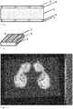
- Konkret wird die Lösung der Aufgabe dadurch erreicht, dass ein Material aus elektrisch leitfähigem Kunststoff (1) mit Elektroden (2), (3) auf der Ober- und Unterseite kontaktiert wird. Zusätzlich befinden sich auf der Oberseite und/oder Unterseite des leitfähigen Kunststoffs Abstandshalter (4) aus einem elektrisch nicht leitfähigen Material (s.
Fig. 1 und Fig. 2 ). Hierdurch erfolgt zwischen den Elektroden kein stoff- oder kraftschlüssiger Kontakt. Erst durch Druckerhöhung infolge einer lokalen Belastung auf der Fläche wird ein enger Kontakt der Elektroden zum Heizkörper hergestellt, wodurch in diesem Bereich Strom fließen kann und Wärme erzeugt wird. - Bei dem elektrisch leitfähigen Kunststoff kann es sich sowohl um einen intrinsisch leitfähigen Kunststoff handeln, als auch um einen Kunststoff, der durch Zusatz von Additiven leitfähig gemacht wurde.
- Als intrinsisch leitfähige Polymere können dotiertes Poly-3,4-ethylendioxythiophen, Polyanilin, Polypyrrol oder Polythiophen eingesetzt werden.
- Nicht intrinsisch elektrisch leitfähige Kunststoffe können durch Zusatz von elektrisch leitfähigen Additiven leitfähig gemacht werden. Geeignete Additive umfassen beispielsweise Ruß, Graphit, Graphen, Metallpartikel und/oder Kohlenstoffnanotubes. Die Kunststoffe umfassen Polymere mit einer ausschließlich aus Kohlenstoff bestehenden Hauptkette, wie z.B. Polyethylen und Polypropylen, außerdem Polyamide, Polyurethane, Polyester und Silikone.
- Der elektrisch leitfähige Kunststoff kann sowohl massiv als auch porös oder geschäumt vorliegen. In Abhängigkeit vom zugrundeliegenden Polymer kann er steif oder flexibel sein.
- Besonders bevorzugt sind leitfähige Kunststoffe mit einem positiven Temperaturkoeffizienten (PTC) des elektrischen Widerstands, die eine selbständige Reduktion des Stroms und damit der Wärmeerzeugung mit zunehmender Temperatur realisieren.
- Die elektrische Leitfähigkeit des Kunststoffs liegt zwischen 102 und 105 S/m, bevorzugt zwischen 102 und 104 S/m.
- Vorteilhafterweise besitzen die flächigen Elektroden eine gewisse mechanische Flexibilität, wodurch ein reversibles Andrücken und Ablösen des Kontaktes an den Heizkörper unter Druck ermöglicht wird. Geeignete flächige Elektroden können z.B. Metallfolien, metallbeschichtete Polymerfolien, metallische Drahtgewebe, metallisierte Gewebe oder leitfähige Schäume sein, die einen ausreichend kleinen elektrischen Zuleitungswiderstand gewährleisten. Das Material des Flächenheizkörpers (1) ist bevorzugt ein leitfähiger Kunststoff in Form einer Folie oder Platte oder ein leitfähiger Schaum.
- Zur Verhinderung des Stromflusses im unbelasteten Zustand ist es nötig zwischen die Elektroden (2), (3) und dem elektrisch leitfähigen Flächenheizkörper (1) in gewissen Abständen punktuell oder linienförmig elektrisch nicht leitende Abstandshalter (4) anzubringen, die verhindern, dass die Elektroden lokal begrenzt zufällig in Kontakt mit dem Flächenheizkörper kommen. Durch das erfindungsgemäße Anbringen der Abstandshalter wird die Stromstärke gänzlich auf null reduziert. Die Abstandshalter (4) können dünne, flexible Schaumstofffolien oder dünne Textilfasern sein. Dabei ist darauf zu achten, dass die von den Abstandshaltern (4) bedeckte Fläche sehr klein, möglichst kleiner als 10%, im Vergleich zur gesamten Fläche der Heizmatte ist.
-
- In einer 1. Ausführungsform besteht der elektrisch leitfähige Kunststoff (1) aus einer leitfähigen Schaumstoffplatte, die Elektroden (2), (3) aus einem metallischen Drahtgewebe und die Abstandshalter (4) aus dünnen Polyesterfasern, die in einem Abstand von mehreren Zentimetern zwischen der Schaumstoffplatte und den Elektroden verlegt sind.
- In einer 2. Ausführungsform sind als Abstandshalter (4) dünne Schaumstoffpads mit einer lateralen Ausdehnung von wenigen Millimetern in einem Abstand von mehreren Zentimetern auf die Schaumstoffplatte aufgeklebt.
- In einer 3. Ausführungsform sind die Elektroden (2), (3) durch ein metallisiertes Gewebe realisiert. Ein wesentlicher Vorteil dieser Elektroden gegenüber dem metallischen Drahtgewebe aus der 1. und 2. Ausführungsform ist die höhere Flexibilität und das geringere Gewicht.
- Dieses Beispiel zeigt das Wirkprinzip der Erfindung. Ein leitfähiger PE-Schaumstoff (ELS-M) mit den Abmessungen 470 x 320 mm und der Dicke 6 mm wird beidseitig mit Netzelektroden aus Edelstahl belegt. Die Netzelektroden bestehen aus Edelstahldrähten mit einer Maschenweite von 1,4 mm und werden am Rand lose am Schaumstoff fixiert. Zwischen die untere Netzelektrode und den leitfähigen Schaumstoff wurden als Abstandshalter PET-Kunststofffilamente mit einem Durchmesser von 0,5 mm im Abstand von ca. 6 cm in das Drahtgewebe eingeflochten. Zwischen die obere Netzelektrode und den leitfähigen Schaumstoff wurden als Abstandshalter 28 Schaumstoffplättchen (2 mm dünn) im Abstand von ca. 8 cm aufgeklebt. Prinzipiell kann man auch andere Materialien und Formkörper als Abstandshalter verwenden, solange sie nicht den flächigen Kontakt der Elektroden zum leitfähigen Schaumstoff im Belastungsfall verhindern.
- Legt man an die Elektroden eine Spannung von 60 Volt, so fließt im unbelasteten Fall durch die Heizmatte kein messbarer Strom. Belastet man die Matte lokal, beginnt an dieser Stelle ein deutlich höherer Strom zu fließen. In einem Beispiel erfolgte die Belastung, vorgegeben durch die Geometrie der Auflage, in einem ringförmigen Bereich mit einem inneren Durchmesser von 3,5 cm und einem äußeren Durchmesser von 6,6 cm. Das entspricht einer Auflagefläche von 24,6 cm2. Belastet man die Fläche mit einer Masse von 9,4 kg, so fließt ein Strom von 140 mA. Das entspricht einer lokalen Stromdichte von 5,7 mA/cm2. Erhöht man die Last auf 13,3 kg, erhöht sich die Stromstärke auf 160 mA respektive 6,5 mA/cm2. Infolge dessen kommt es zu einer Temperaturerhöhung um 30 - 35 K im Vergleich zum unbelasteten Teil der Matte.
- In einer zweiten Variante wird der zentrale Teil der Matte im Bereich eines Rechtecks von 31x20 cm mit einem Gewicht von 80 kg beaufschlagt. Die Stromstärke beträgt jetzt 1,3 A und die lokale Stromdichte 2,1 mA/cm2.
- Betritt eine Person mit einem Gewicht von ca. 75 kg, die Matte, so fließt ein Strom von 1,34 A. Mit der Annahme einer Sohlenfläche von ca. 500 cm2 ergibt sich eine Stromdichte von 2,7 mA/cm2. Die so generierte elektrische Leistung von 80 Watt führt zu einer schnellen Aufheizung der Matte unterhalb der Füße, wobei nach ca. 10 Sekunden eine Temperaturerhöhung zwischen 15 und 25 Grad je nach Fußkontakt mittels Thermografie nachweisbar ist (
Fig. 3 ). - Dieses Beispiel zeigt die Bedeutung der Abstandshalter für die Reduzierung des Ruhestroms im unbelasteten Fall, dadurch dass keine Abstandshalter verwendet werden. Ein leitfähiger Schaumstoff mit den Abmessungen 21 x 21 cm und der Dicke 7 mm wird beidseitig mit Netzelektroden aus Edelstahl belegt. Die Netzelektroden bestehen aus Edelstahldrähten mit einer Maschenweite von 1,4 mm und werden am Rand lose am Schaumstoff fixiert. Abstandshalter fehlen. Legt man an die Elektroden eine Spannung von 60 Volt, so fließt ohne Belastung durch die Heizmatte ein kleiner aber gut messbarer Strom von 10 mA, der durch zufällige punktuelle Kontakte verursacht wird. Belastet man die Matte lokal, beginnt an dieser Stelle ein höherer Strom vergleichbar wie in Beispiel 1, zu fließen.
-
- 1
- leitfähiger Kunststoff
- 2
- obere Elektrode
- 3
- untere Elektrode
- 4
- Abstandshalter
- 5
- Heizmatte
Claims (10)
- Elektrische Flächenheizung umfassend oder bestehend aus einem elektrisch leitfähigen Kunststoffkörper sowie einer oberen und einer unteren Elektrode an denen eine elektrische Spannung anliegt, dadurch gekennzeichnet, dass mindestens eine der beiden Elektroden flexibel ist und zwischen oberer Elektrode und Kunststoffkörper und/oder unterer Elektrode und Kunststoffkörper in definierten Abständen räumlich eng begrenzt dünne Abstandshalterhalter aufgebracht sind, so dass im unbelasteten Zustand kein Strom fließt, bei Belastung jedoch sich die flexible Elektrode durchbiegt und einen stoffschlüssigen Kontakt mit dem elektrisch leitfähigen Kunststoffkörper bildet, und damit ein lokaler Stromfluss und eine Erwärmung realisiert wird.
- Elektrische Flächenheizung nach Anspruch 1, dadurch gekennzeichnet, dass der elektrisch leitfähige Kunststoffkörper intrinsisch leitfähig ist, und bevorzugt dotiertes Poly-3,4-ethylendioxythiophen, Polyanilin, Polypyrrol oder Polythiophen enthält oder daraus besteht.
- Elektrische Flächenheizung nach Anspruch 1, dadurch gekennzeichnet, dass der elektrisch leitfähige Kunststoffkörper durch Zusatz von Additiven leitfähig gemacht ist, bevorzugt durch Zusatz von Ruß, Graphit, Graphen, Metallpartikel und/oder Kohlenstoffnanotubes.
- Elektrisch leitfähiger Kunststoffkörper nach Anspruch 3, dadurch gekennzeichnet, dass der Kunststoff ausgewählt wird aus der Gruppe der Polymere mit einer ausschließlich aus Kohlenstoff bestehenden Hauptkette, bevorzugt, Polyethylen-vinylacetat-Copolymer oder aus der Gruppe Polyethylen, Polypropylen, Polyvinylfluorid, Polyvinylidenfluorid, Polyvinylchlorid, Polyvinylidenchlorid der Polyamide, Polyurethane, Polyester oder Silikone.
- Elektrisch leitfähiger Kunststoffkörper nach Anspruch 1, dadurch gekennzeichnet, dass der Körper entweder massiv oder porös oder geschäumt vorliegt.
- Elektrisch leitfähiger Kunststoffkörper nach Anspruch 1, dadurch gekennzeichnet, dass er einen positiven Temperaturkoeffizienten (PTC) des elektrischen Widerstands besitzt.
- Elektrisch leitfähiger Kunststoffkörper nach Anspruch 1, dadurch gekennzeichnet, dass die elektrische Leitfähigkeit des Kunststoffs zwischen 102 und 105 S/m, bevorzugt zwischen 102 und 104 S/m liegt.
- Elektrische Flächenheizung nach Anspruch 1 dadurch gekennzeichnet, dass die flächigen Elektroden z.B. Metallfolien, metallbeschichtete Polymerfolien, metallische Drahtgewebe, metallisierte Gewebe oder leitfähige Schäume sein können
- Elektrische Flächenheizung nach Anspruch 1, dadurch gekennzeichnet, dass die Abstandshalter elektrisch nicht leitfähig sind und in gewissen Abständen punktuell oder linienförmig auf der Ober- und/oder Unterseite des elektrisch leitfähigen Kunststoffkörper angebracht sind.
- Abstandshalter nach Anspruch 9, dadurch gekennzeichnet, dass es sich um Schaumstofffolien oder Textilfasern handelt und die von den Abstandshaltern bedeckte Fläche kleiner als 10% der Gesamtfläche des elektrisch leitfähigen Kunststoffkörpers ist.
Applications Claiming Priority (1)
| Application Number | Priority Date | Filing Date | Title |
|---|---|---|---|
| DE102020100226.2A DE102020100226A1 (de) | 2020-01-08 | 2020-01-08 | Elektrische Heizmatte |
Publications (3)
| Publication Number | Publication Date |
|---|---|
| EP3849277A1 true EP3849277A1 (de) | 2021-07-14 |
| EP3849277C0 EP3849277C0 (de) | 2025-08-13 |
| EP3849277B1 EP3849277B1 (de) | 2025-08-13 |
Family
ID=74105902
Family Applications (1)
| Application Number | Title | Priority Date | Filing Date |
|---|---|---|---|
| EP21150516.9A Active EP3849277B1 (de) | 2020-01-08 | 2021-01-07 | Elektrische heizmatte |
Country Status (6)
| Country | Link |
|---|---|
| US (1) | US20210207815A1 (de) |
| EP (1) | EP3849277B1 (de) |
| JP (1) | JP7690183B2 (de) |
| KR (1) | KR20210089586A (de) |
| CN (1) | CN113099561A (de) |
| DE (1) | DE102020100226A1 (de) |
Families Citing this family (3)
| Publication number | Priority date | Publication date | Assignee | Title |
|---|---|---|---|---|
| WO2020118117A1 (en) * | 2018-12-05 | 2020-06-11 | Battelle Memorial Institute | Flexible foam resistive heaters and methods of making flexible resistive heaters |
| KR20230007885A (ko) * | 2021-07-06 | 2023-01-13 | 현대자동차주식회사 | 압력감응형 발열체 및 그 제조방법 |
| NL2035941B1 (en) * | 2023-10-02 | 2025-04-10 | Stichting Ziekenhuisgroep Twente | An assembly and a method for determining a temperature distribution of a foot. |
Citations (5)
| Publication number | Priority date | Publication date | Assignee | Title |
|---|---|---|---|---|
| JPH02234379A (ja) * | 1989-03-07 | 1990-09-17 | Matsushita Electric Ind Co Ltd | 床暖房装置 |
| US6906293B2 (en) * | 2000-05-17 | 2005-06-14 | I.E.E. International Electronics & Engineering S.Ar.L | Combined sensor and heating element |
| DE102004058721A1 (de) * | 2003-12-04 | 2005-07-28 | Iq-Mobil Gmbh | Vorrichtung zur Erwärmung einer Oberfläche |
| DE112012005448T5 (de) * | 2011-12-21 | 2014-09-18 | Iee International Electronics & Engineering S.A. | Belegungssensor für belegungsfähigen Gegenstand, zum Beispiel einen Sitz oder ein Bett |
| WO2017098842A1 (ja) * | 2015-12-09 | 2017-06-15 | 株式会社デンソー | ヒータ装置、およびヒータ装置の製造方法 |
Family Cites Families (10)
| Publication number | Priority date | Publication date | Assignee | Title |
|---|---|---|---|---|
| US4060710A (en) * | 1971-09-27 | 1977-11-29 | Reuter Maschinen-And Werkzeugbau Gmbh | Rigid electric surface heating element |
| US4517449A (en) * | 1983-05-11 | 1985-05-14 | Raychem Corporation | Laminar electrical heaters |
| JPS63279588A (ja) * | 1987-05-11 | 1988-11-16 | Hitachi Cable Ltd | 有機ヒ−タ素子 |
| AT406924B (de) * | 1998-02-02 | 2000-10-25 | Manfred Dr Elsaesser | Heizelement |
| JP5201137B2 (ja) | 2007-01-22 | 2013-06-05 | パナソニック株式会社 | 高分子抵抗体 |
| JP2010040186A (ja) * | 2008-07-31 | 2010-02-18 | Aisin Seiki Co Ltd | ヒータ装置 |
| DE102011014516A1 (de) * | 2010-04-06 | 2012-05-10 | W.E.T. Automotive Systems Ag | Multifunktionsprodukt |
| SG10202005956RA (en) * | 2015-12-23 | 2020-07-29 | Fisher & Paykel Healthcare Ltd | Heating arrangements for humidification systems |
| CN107426836B (zh) * | 2017-09-11 | 2018-06-26 | 南京银纳新材料科技有限公司 | 一种基于金属纳米线薄膜的非矩形面加热器 |
| KR102041269B1 (ko) * | 2019-05-20 | 2019-11-06 | 유한회사 대동 | 눈 보호구용 투명 발열체 및 그의 제조방법 |
-
2020
- 2020-01-08 DE DE102020100226.2A patent/DE102020100226A1/de active Pending
-
2021
- 2021-01-06 KR KR1020210001371A patent/KR20210089586A/ko not_active Ceased
- 2021-01-07 US US17/143,308 patent/US20210207815A1/en not_active Abandoned
- 2021-01-07 EP EP21150516.9A patent/EP3849277B1/de active Active
- 2021-01-08 JP JP2021001864A patent/JP7690183B2/ja active Active
- 2021-01-08 CN CN202110021616.7A patent/CN113099561A/zh active Pending
Patent Citations (5)
| Publication number | Priority date | Publication date | Assignee | Title |
|---|---|---|---|---|
| JPH02234379A (ja) * | 1989-03-07 | 1990-09-17 | Matsushita Electric Ind Co Ltd | 床暖房装置 |
| US6906293B2 (en) * | 2000-05-17 | 2005-06-14 | I.E.E. International Electronics & Engineering S.Ar.L | Combined sensor and heating element |
| DE102004058721A1 (de) * | 2003-12-04 | 2005-07-28 | Iq-Mobil Gmbh | Vorrichtung zur Erwärmung einer Oberfläche |
| DE112012005448T5 (de) * | 2011-12-21 | 2014-09-18 | Iee International Electronics & Engineering S.A. | Belegungssensor für belegungsfähigen Gegenstand, zum Beispiel einen Sitz oder ein Bett |
| WO2017098842A1 (ja) * | 2015-12-09 | 2017-06-15 | 株式会社デンソー | ヒータ装置、およびヒータ装置の製造方法 |
Also Published As
| Publication number | Publication date |
|---|---|
| JP7690183B2 (ja) | 2025-06-10 |
| US20210207815A1 (en) | 2021-07-08 |
| CN113099561A (zh) | 2021-07-09 |
| DE102020100226A1 (de) | 2021-07-08 |
| EP3849277C0 (de) | 2025-08-13 |
| JP2021131221A (ja) | 2021-09-09 |
| EP3849277B1 (de) | 2025-08-13 |
| KR20210089586A (ko) | 2021-07-16 |
Similar Documents
| Publication | Publication Date | Title |
|---|---|---|
| EP3849277B1 (de) | Elektrische heizmatte | |
| EP1554911B1 (de) | Flächenheizung, verfahren zu deren herstellung und heizbarer gegenstand sowie sitzbelegungserkennung, sitz damit und sitzbelegungserkennungsverfahren | |
| WO2004082989A2 (de) | Vorrichtung zur aufnahme von funktionselementen | |
| WO2004082969A2 (de) | Vorrichtung zur klimatisierung eines fahrzeuges | |
| US7196288B2 (en) | Flexible heating element | |
| DE102013006410A1 (de) | Flächengebilde mit elektrischer Funktion | |
| EP3085198B1 (de) | Elektrisch heizbares flächenelement | |
| EP1924125A1 (de) | Heizbare Folie | |
| DE102011105675A1 (de) | Elektrische Leitung | |
| EP2127473A2 (de) | Blattheizelement | |
| EP0991347B1 (de) | Stützteil für einen sitz | |
| JP2018060760A (ja) | 面状発熱体、面状発熱装置、面状発熱体用電極、及び面状発熱体の製造方法 | |
| US20130264332A1 (en) | Conductive elastomeric heater with expandable core | |
| JP2013191551A (ja) | 面状発熱体及びその製造方法並びに面状発熱体用電極 | |
| DE112016006301B4 (de) | Heizvorrichtung | |
| DE102015105004B3 (de) | Textilmaterial mit eingearbeiteten Elastomersensoren | |
| CN112601789A (zh) | 复合材料 | |
| WO2004082990A1 (de) | Klimatisierungsvorrichtung für einen fahrgastraum eines fahrzeuges | |
| DE102009016965B4 (de) | Flexibles Flächengebilde, Sitzvorrichtung mit Beheizung und Sitzbelegungserkennung und Verfahren zum Betreiben eines flexiblen Flächengebildes | |
| DE19730853B4 (de) | Anordnung zum Einschalten von Verbrauchern | |
| WO2004095986A1 (de) | Einlage zur klimatisierung | |
| EP1547442A2 (de) | Heizleiter und verwendung des heizleiters | |
| EP3986088A1 (de) | Wärmekissen für den menschlichen körper zur linderung von körperlichen beschwerden | |
| WO2017028836A1 (de) | Temperatursensoreinheit und anordnung eines temperatursensors an bzw. in einer temperierungseinrichtung | |
| EP3621409A1 (de) | Heizfolie und heizplatte |
Legal Events
| Date | Code | Title | Description |
|---|---|---|---|
| PUAI | Public reference made under article 153(3) epc to a published international application that has entered the european phase |
Free format text: ORIGINAL CODE: 0009012 |
|
| STAA | Information on the status of an ep patent application or granted ep patent |
Free format text: STATUS: THE APPLICATION HAS BEEN PUBLISHED |
|
| AK | Designated contracting states |
Kind code of ref document: A1 Designated state(s): AL AT BE BG CH CY CZ DE DK EE ES FI FR GB GR HR HU IE IS IT LI LT LU LV MC MK MT NL NO PL PT RO RS SE SI SK SM TR |
|
| STAA | Information on the status of an ep patent application or granted ep patent |
Free format text: STATUS: REQUEST FOR EXAMINATION WAS MADE |
|
| 17P | Request for examination filed |
Effective date: 20220105 |
|
| RBV | Designated contracting states (corrected) |
Designated state(s): AL AT BE BG CH CY CZ DE DK EE ES FI FR GB GR HR HU IE IS IT LI LT LU LV MC MK MT NL NO PL PT RO RS SE SI SK SM TR |
|
| GRAP | Despatch of communication of intention to grant a patent |
Free format text: ORIGINAL CODE: EPIDOSNIGR1 |
|
| STAA | Information on the status of an ep patent application or granted ep patent |
Free format text: STATUS: GRANT OF PATENT IS INTENDED |
|
| INTG | Intention to grant announced |
Effective date: 20250314 |
|
| GRAS | Grant fee paid |
Free format text: ORIGINAL CODE: EPIDOSNIGR3 |
|
| GRAA | (expected) grant |
Free format text: ORIGINAL CODE: 0009210 |
|
| STAA | Information on the status of an ep patent application or granted ep patent |
Free format text: STATUS: THE PATENT HAS BEEN GRANTED |
|
| AK | Designated contracting states |
Kind code of ref document: B1 Designated state(s): AL AT BE BG CH CY CZ DE DK EE ES FI FR GB GR HR HU IE IS IT LI LT LU LV MC MK MT NL NO PL PT RO RS SE SI SK SM TR |
|
| REG | Reference to a national code |
Ref country code: GB Ref legal event code: FG4D Free format text: NOT ENGLISH |
|
| REG | Reference to a national code |
Ref country code: CH Ref legal event code: EP |
|
| REG | Reference to a national code |
Ref country code: DE Ref legal event code: R096 Ref document number: 502021008279 Country of ref document: DE |
|
| REG | Reference to a national code |
Ref country code: IE Ref legal event code: FG4D Free format text: LANGUAGE OF EP DOCUMENT: GERMAN |
|
| U01 | Request for unitary effect filed |
Effective date: 20250908 |
|
| U07 | Unitary effect registered |
Designated state(s): AT BE BG DE DK EE FI FR IT LT LU LV MT NL PT RO SE SI Effective date: 20250912 |
|
| PG25 | Lapsed in a contracting state [announced via postgrant information from national office to epo] |
Ref country code: IS Free format text: LAPSE BECAUSE OF FAILURE TO SUBMIT A TRANSLATION OF THE DESCRIPTION OR TO PAY THE FEE WITHIN THE PRESCRIBED TIME-LIMIT Effective date: 20251213 |
|
| PG25 | Lapsed in a contracting state [announced via postgrant information from national office to epo] |
Ref country code: NO Free format text: LAPSE BECAUSE OF FAILURE TO SUBMIT A TRANSLATION OF THE DESCRIPTION OR TO PAY THE FEE WITHIN THE PRESCRIBED TIME-LIMIT Effective date: 20251113 |
|
| PG25 | Lapsed in a contracting state [announced via postgrant information from national office to epo] |
Ref country code: HR Free format text: LAPSE BECAUSE OF FAILURE TO SUBMIT A TRANSLATION OF THE DESCRIPTION OR TO PAY THE FEE WITHIN THE PRESCRIBED TIME-LIMIT Effective date: 20250813 |
|
| PG25 | Lapsed in a contracting state [announced via postgrant information from national office to epo] |
Ref country code: GR Free format text: LAPSE BECAUSE OF FAILURE TO SUBMIT A TRANSLATION OF THE DESCRIPTION OR TO PAY THE FEE WITHIN THE PRESCRIBED TIME-LIMIT Effective date: 20251114 |
|
| PG25 | Lapsed in a contracting state [announced via postgrant information from national office to epo] |
Ref country code: PL Free format text: LAPSE BECAUSE OF FAILURE TO SUBMIT A TRANSLATION OF THE DESCRIPTION OR TO PAY THE FEE WITHIN THE PRESCRIBED TIME-LIMIT Effective date: 20250813 |
|
| PG25 | Lapsed in a contracting state [announced via postgrant information from national office to epo] |
Ref country code: RS Free format text: LAPSE BECAUSE OF FAILURE TO SUBMIT A TRANSLATION OF THE DESCRIPTION OR TO PAY THE FEE WITHIN THE PRESCRIBED TIME-LIMIT Effective date: 20251113 |
|
| PG25 | Lapsed in a contracting state [announced via postgrant information from national office to epo] |
Ref country code: ES Free format text: LAPSE BECAUSE OF FAILURE TO SUBMIT A TRANSLATION OF THE DESCRIPTION OR TO PAY THE FEE WITHIN THE PRESCRIBED TIME-LIMIT Effective date: 20250813 |
|
| U20 | Renewal fee for the european patent with unitary effect paid |
Year of fee payment: 6 Effective date: 20260129 |
|
| PG25 | Lapsed in a contracting state [announced via postgrant information from national office to epo] |
Ref country code: SM Free format text: LAPSE BECAUSE OF FAILURE TO SUBMIT A TRANSLATION OF THE DESCRIPTION OR TO PAY THE FEE WITHIN THE PRESCRIBED TIME-LIMIT Effective date: 20250813 |
|
| PG25 | Lapsed in a contracting state [announced via postgrant information from national office to epo] |
Ref country code: CZ Free format text: LAPSE BECAUSE OF FAILURE TO SUBMIT A TRANSLATION OF THE DESCRIPTION OR TO PAY THE FEE WITHIN THE PRESCRIBED TIME-LIMIT Effective date: 20250813 |
|
| PG25 | Lapsed in a contracting state [announced via postgrant information from national office to epo] |
Ref country code: SK Free format text: LAPSE BECAUSE OF FAILURE TO SUBMIT A TRANSLATION OF THE DESCRIPTION OR TO PAY THE FEE WITHIN THE PRESCRIBED TIME-LIMIT Effective date: 20250813 |
|
| PLBE | No opposition filed within time limit |
Free format text: ORIGINAL CODE: 0009261 |
|
| STAA | Information on the status of an ep patent application or granted ep patent |
Free format text: STATUS: NO OPPOSITION FILED WITHIN TIME LIMIT |
|
| REG | Reference to a national code |
Ref country code: CH Ref legal event code: L10 Free format text: ST27 STATUS EVENT CODE: U-0-0-L10-L00 (AS PROVIDED BY THE NATIONAL OFFICE) Effective date: 20260624 |
|
| 26N | No opposition filed |
Effective date: 20260515 |