EP3849046A1 - Electricity storage device and charging method - Google Patents
Electricity storage device and charging method Download PDFInfo
- Publication number
- EP3849046A1 EP3849046A1 EP19857029.3A EP19857029A EP3849046A1 EP 3849046 A1 EP3849046 A1 EP 3849046A1 EP 19857029 A EP19857029 A EP 19857029A EP 3849046 A1 EP3849046 A1 EP 3849046A1
- Authority
- EP
- European Patent Office
- Prior art keywords
- power storage
- charging
- storage units
- series
- total
- Prior art date
- Legal status (The legal status is an assumption and is not a legal conclusion. Google has not performed a legal analysis and makes no representation as to the accuracy of the status listed.)
- Pending
Links
Images


Classifications
-
- H—ELECTRICITY
- H02—GENERATION; CONVERSION OR DISTRIBUTION OF ELECTRIC POWER
- H02J—ELECTRIC POWER NETWORKS; CIRCUIT ARRANGEMENTS OR SYSTEMS FOR SUPPLYING OR DISTRIBUTING ELECTRIC POWER; SYSTEMS FOR STORING ELECTRIC ENERGY
- H02J7/00—Circuit arrangements for charging or discharging batteries or for supplying loads from batteries
- H02J7/50—Circuit arrangements for charging or discharging batteries or for supplying loads from batteries acting upon multiple batteries simultaneously or sequentially
- H02J7/52—Circuit arrangements for charging or discharging batteries or for supplying loads from batteries acting upon multiple batteries simultaneously or sequentially for charge balancing, e.g. equalisation of charge between batteries
- H02J7/54—Passive balancing, e.g. using resistors or parallel MOSFETs
-
- H—ELECTRICITY
- H01—ELECTRIC ELEMENTS
- H01M—PROCESSES OR MEANS, e.g. BATTERIES, FOR THE DIRECT CONVERSION OF CHEMICAL ENERGY INTO ELECTRICAL ENERGY
- H01M10/00—Secondary cells; Manufacture thereof
- H01M10/42—Methods or arrangements for servicing or maintenance of secondary cells or secondary half-cells
- H01M10/44—Methods for charging or discharging
- H01M10/441—Methods for charging or discharging for several batteries or cells simultaneously or sequentially
-
- H—ELECTRICITY
- H01—ELECTRIC ELEMENTS
- H01M—PROCESSES OR MEANS, e.g. BATTERIES, FOR THE DIRECT CONVERSION OF CHEMICAL ENERGY INTO ELECTRICAL ENERGY
- H01M10/00—Secondary cells; Manufacture thereof
- H01M10/42—Methods or arrangements for servicing or maintenance of secondary cells or secondary half-cells
- H01M10/48—Accumulators combined with arrangements for measuring, testing or indicating the condition of cells, e.g. the level or density of the electrolyte
-
- H—ELECTRICITY
- H01—ELECTRIC ELEMENTS
- H01M—PROCESSES OR MEANS, e.g. BATTERIES, FOR THE DIRECT CONVERSION OF CHEMICAL ENERGY INTO ELECTRICAL ENERGY
- H01M50/00—Constructional details or processes of manufacture of the non-active parts of electrochemical cells other than fuel cells, e.g. hybrid cells
- H01M50/50—Current conducting connections for cells or batteries
- H01M50/502—Interconnectors for connecting terminals of adjacent batteries; Interconnectors for connecting cells outside a battery casing
- H01M50/509—Interconnectors for connecting terminals of adjacent batteries; Interconnectors for connecting cells outside a battery casing characterised by the type of connection, e.g. mixed connections
- H01M50/51—Connection only in series
-
- H—ELECTRICITY
- H02—GENERATION; CONVERSION OR DISTRIBUTION OF ELECTRIC POWER
- H02J—ELECTRIC POWER NETWORKS; CIRCUIT ARRANGEMENTS OR SYSTEMS FOR SUPPLYING OR DISTRIBUTING ELECTRIC POWER; SYSTEMS FOR STORING ELECTRIC ENERGY
- H02J7/00—Circuit arrangements for charging or discharging batteries or for supplying loads from batteries
- H02J7/02—Circuit arrangements for charging or discharging batteries or for supplying loads from batteries for charging batteries from AC mains by converters
-
- H—ELECTRICITY
- H02—GENERATION; CONVERSION OR DISTRIBUTION OF ELECTRIC POWER
- H02J—ELECTRIC POWER NETWORKS; CIRCUIT ARRANGEMENTS OR SYSTEMS FOR SUPPLYING OR DISTRIBUTING ELECTRIC POWER; SYSTEMS FOR STORING ELECTRIC ENERGY
- H02J7/00—Circuit arrangements for charging or discharging batteries or for supplying loads from batteries
- H02J7/50—Circuit arrangements for charging or discharging batteries or for supplying loads from batteries acting upon multiple batteries simultaneously or sequentially
- H02J7/52—Circuit arrangements for charging or discharging batteries or for supplying loads from batteries acting upon multiple batteries simultaneously or sequentially for charge balancing, e.g. equalisation of charge between batteries
- H02J7/56—Active balancing, e.g. using capacitor-based, inductor-based or DC-DC converters
-
- H—ELECTRICITY
- H02—GENERATION; CONVERSION OR DISTRIBUTION OF ELECTRIC POWER
- H02J—ELECTRIC POWER NETWORKS; CIRCUIT ARRANGEMENTS OR SYSTEMS FOR SUPPLYING OR DISTRIBUTING ELECTRIC POWER; SYSTEMS FOR STORING ELECTRIC ENERGY
- H02J7/00—Circuit arrangements for charging or discharging batteries or for supplying loads from batteries
- H02J7/90—Regulation of charging or discharging current or voltage
- H02J7/96—Regulation of charging or discharging current or voltage in response to battery voltage
-
- H—ELECTRICITY
- H02—GENERATION; CONVERSION OR DISTRIBUTION OF ELECTRIC POWER
- H02J—ELECTRIC POWER NETWORKS; CIRCUIT ARRANGEMENTS OR SYSTEMS FOR SUPPLYING OR DISTRIBUTING ELECTRIC POWER; SYSTEMS FOR STORING ELECTRIC ENERGY
- H02J7/00—Circuit arrangements for charging or discharging batteries or for supplying loads from batteries
- H02J7/80—Circuit arrangements for charging or discharging batteries or for supplying loads from batteries including monitoring or indicating arrangements
-
- H—ELECTRICITY
- H02—GENERATION; CONVERSION OR DISTRIBUTION OF ELECTRIC POWER
- H02J—ELECTRIC POWER NETWORKS; CIRCUIT ARRANGEMENTS OR SYSTEMS FOR SUPPLYING OR DISTRIBUTING ELECTRIC POWER; SYSTEMS FOR STORING ELECTRIC ENERGY
- H02J9/00—Circuit arrangements for emergency or stand-by power supply, e.g. for emergency lighting
- H02J9/04—Circuit arrangements for emergency or stand-by power supply, e.g. for emergency lighting in which the distribution system is disconnected from the normal source and connected to a standby source
- H02J9/06—Circuit arrangements for emergency or stand-by power supply, e.g. for emergency lighting in which the distribution system is disconnected from the normal source and connected to a standby source with automatic change-over, e.g. UPS systems
- H02J9/062—Circuit arrangements for emergency or stand-by power supply, e.g. for emergency lighting in which the distribution system is disconnected from the normal source and connected to a standby source with automatic change-over, e.g. UPS systems for AC powered loads
-
- Y—GENERAL TAGGING OF NEW TECHNOLOGICAL DEVELOPMENTS; GENERAL TAGGING OF CROSS-SECTIONAL TECHNOLOGIES SPANNING OVER SEVERAL SECTIONS OF THE IPC; TECHNICAL SUBJECTS COVERED BY FORMER USPC CROSS-REFERENCE ART COLLECTIONS [XRACs] AND DIGESTS
- Y02—TECHNOLOGIES OR APPLICATIONS FOR MITIGATION OR ADAPTATION AGAINST CLIMATE CHANGE
- Y02E—REDUCTION OF GREENHOUSE GAS [GHG] EMISSIONS, RELATED TO ENERGY GENERATION, TRANSMISSION OR DISTRIBUTION
- Y02E60/00—Enabling technologies; Technologies with a potential or indirect contribution to GHG emissions mitigation
- Y02E60/10—Energy storage using batteries
Definitions
- the present invention relates to a power storage device and a charging method.
- a power storage system such as an uninterruptible power supply device can supply electric power to a load device for a certain period of time even during power outage, and thus it has been widely used as a backup power supply for BCP countermeasures in the event of a disaster, for example.
- the power storage system branches the AC power to receive power, and converts the received power into DC power, and then charges a storage battery by a charging circuit.
- the power storage system maintains power supply to the load device by converting the power charged in the storage battery into AC power with an inverter and supplying the AC power to the load device.
- the power storage system as described above can be easily managed by configuring the power storage system as a power storage unit including a plurality of storage batteries, and it is further adaptable to a load device requiring a high voltage by connecting a plurality of power storage units in series.
- a charging voltage is applied to the whole of the plurality of power storage units connected in series at the time of charging, and when variation occurs among respective unit voltages of the plurality of power storage units, from the viewpoint of preventing overcharging, it is necessary to terminate charging at the time point when any unit voltage has reached full charge. Therefore, the power storage system as described above may be restricted to perform charging and discharging with only a power capacity smaller than the originally designed capacity.
- a battery system is constructed in a prior art described in Patent Document 1 by a storage battery group A including a plurality of storage batteries connected in series and one storage battery B having a lower capacity than the storage battery group A, which are connected in series.
- the prior art of Patent Document 1 prevents all the storage batteries included in the storage battery group A from being overcharged and overdischarged by managing SOC (State of Charge) of the storage battery group A within a certain range.
- Patent Document 1 Japanese Patent Laid-Open No. 2010-9840
- the above-mentioned prior art is intended to suppress occurrence of overcharging and overdischarging by equalizing the SOCs of the plurality of storage batteries, but a configuration thereof for that purpose limits the power capacity which can be charged in the storage batteries included in the battery system.
- An object of the present invention which has been made in view of such a situation, is to provide a power storage device capable of suppressing reduction in rechargeable power capacity while equalizing the capacities of a plurality of power storage units connected in series during charging of the plurality of power storage units, and a method of charging the power storage device.
- an aspect of the present invention is directed to a power storage device comprising: a plurality of power storage units connected in series; and a control unit for monitoring a unit voltage of each of the plurality of power storage units and controlling each of the plurality of power storage units, wherein each of the power storage units includes an power storage portion and a charge switch which are connected to each other in series between charge/discharge terminals, and a bypass switch providing a bypass between the charge/discharge terminals, and for the plurality of power storage units to be charged in series, the control unit individually sets a charging mode in which the power storage portion is charged with a constant current by controlling the bypass switch to be set to OFF while controlling the charge switch to be set to ON, and a bypass mode in which the charging of the power storage portion is stopped by controlling the bypass switch to be set to ON while controlling the charge switch to be set to OFF, thereby equalizing the unit voltages.
- a power storage device capable of suppressing reduction in rechargeable power capacity while equalizing capacities of a plurality of power storage units connected in series during charging of the plurality of power storage units, and a method of charging the power storage device.
- FIG. 1 is a circuit diagram of a backup power supply using a power storage device 1 according to the present invention. More specifically, FIG. 1 is a circuit diagram illustrating the configuration of a backup power supply provided in a power supply path from a commercial power source 2 to a load 3.
- the power storage device 1 is a so-called uninterruptible power system (UPS) that can be charged with power supplied from the commercial power source 2 and enables power supply to the load 3 to be continued by discharging under power outage of the commercial power source 2.
- UPS uninterruptible power system
- power of AC100V output from the commercial power source 2 is converted to DC380V in a power supply circuit 4, and supplied to a switching circuit 5.
- the power of DC380V supplied to the switching circuit 5 is reconverted to AC100V in an inverter 6, and output to the load 3.
- the power of AC100V output from the commercial power source 2 is converted into DC power in a charging circuit 7, and also converted into a voltage required by the power storage device 1 to be used for charging the power storage device 1.
- the power storage device 1 When power outage occurs in the commercial power source 2, the power storage device 1 outputs DC power to the inverter 6 via the switching circuit 5. As a result, the power of DC380V output from the power storage device 1 is reconverted to AC100V in the inverter 6 and output to the load 3.
- the switching circuit 5 outputs the power input from the power supply circuit 4 to the inverter 6 in normal times when no power outage occurs, and outputs the power input from the power storage device 1 to the inverter 6 when power outage occurs, whereby the power supply source is switched.
- the configuration of the backup power supply using the power storage device 1 of the present invention is not limited to the circuit configuration described above, and various changes can be made depending on conditions such as applicable equipment, etc.
- FIG. 2 is a circuit diagram showing the configuration of the power storage device 1 according to the present invention.
- the power storage device 1 includes a first power storage unit BBU1 to a seventh power storage unit BBU7 which are connected in series, and a control unit 10.
- the number of power storage units included in the power storage device 1 is not limited to this number, and the number is appropriately adjusted so as to obtain an output voltage required for the load 3.
- the first power storage unit BBU1 has charge/discharge terminals T(-) and T(+) formed therein, and includes an power storage portion BAT and a charge switch SW C that are connected in series between the charge/discharge terminals in the first power storage unit BBU1. Further, the first power storage unit BBU1 includes a discharge switch SW D which is connected in parallel with the charge switch SW C . Further, the first power storage unit BBU1 has a bypass path formed between the charge/discharge terminals, and a bypass switch SW B is provided in the bypass path.
- the power storage portion BAT is made up of a plurality of battery cells each made of, for example, a nickel metal hydrogen battery or a nickel cadmium battery, which are connected in series.
- the charge switch SW C , the discharge switch SW D , and the bypass switch SW B are composed of switching elements operating at high speed, such as MOSFETs (Metal-Oxide-Semiconductor Field-Effect Transistors) and IGBTs (Insulated Gate Bipolar Transistors).
- MOSFETs Metal-Oxide-Semiconductor Field-Effect Transistors
- IGBTs Insulated Gate Bipolar Transistors
- the charge switch SW C is controlled to be set to ON, the discharge switch SW D is controlled to be set to OFF, and the bypass switch SW B is controlled to be set to OFF, whereby the first power storage unit BBU1 is set to a charging mode in which the power storage portion BAT is charged with a charging voltage applied between the charge/discharge terminals. Further, the charge switch SW C is controlled to be set to OFF, the discharge switch SW D is controlled to be set to ON, and the bypass switch SW B is controlled to be set to OFF, whereby the first power storage unit BBU1 is set to a discharging mode in which the voltage of the power storage portion BAT as a unit voltage is output between the charge/discharge terminals.
- a second power storage unit BBU2 to the seventh power storage unit BBU7 are the same as the configuration of the first power storage unit BBU1 described above, and thus detailed description thereof will be omitted.
- the control unit 10 is a so-called BMS (Battery Management System) that includes, for example, a well-known microcomputer control circuit and controls charging/discharging of the power storage device 1.
- BMS Battery Management System
- the control unit 10 receives power from the charging circuit 7, and applies a charging voltage V C between the charge/discharge terminal T(-) of the first power storage unit BBU1 and the charge/discharge terminal T(+) of the seventh power storage unit BBU7. Further, when discharging the power storage device 1, the control unit 10 supplies the switching circuit 5 with a total voltage V TOTAL between the charge/discharge terminal T(-) of the first power storage unit BBU1 and the charge/discharge terminal T(+) of the seventh power storage unit BBU7.
- control unit 10 is configured to be capable of monitoring the respective unit voltages of the first power storage unit BBU1 to the seventh power storage unit BBU7, and individually controlling the charge switch SW C , the discharge switch SW D , and the bypass switch SW B of each of the power storage units.
- the control unit 10 can set a bypass mode in which charging for a specific power storage unit is stopped. More specifically, for example, when setting the first power storage unit BBU1 to the bypass mode, the control unit 10 controls the charge switch SW C , the discharge switch SW D and the bypass switch SW B of the first power storage unit BBU1 to be set to OFF, OFF and ON respectively, whereby the charge/discharge terminals of the first power storage unit BBU1 are shortcircuited to prohibit the power storage portion BAT from being charged. In this case, in the series charging of the respective power storage units, the second power storage unit BBU2 to the seventh power storage unit BBU7 are charged, whereas the first power storage unit BBU1 is excluded from the series charging.
- the power storage device 1 can arbitrarily set a timing of charging in a case where the total voltage V TOTAL , which is the total of the unit voltages of the first power storage unit BBU1 to the seventh power storage unit BBU7, drops to a predetermined threshold value or less, in a case of recovering from power outage, and the like.
- the total voltage V TOTAL which is the total of the unit voltages of the first power storage unit BBU1 to the seventh power storage unit BBU7
- V CUTOFF a discharge termination voltage
- the total voltage V TOTAL in the present embodiment will be described on the assumption that the discharge termination voltage V CUTOFF is 265 V and a charging upper limit voltage is 380 V.
- control unit 10 continuously monitors the voltage of each of the power storage portions BAT of the first power storage unit BBU1 to the seventh power storage unit BBU7 at least during charging of the power storage device 1 (voltage monitoring step). Further, the control unit 10 performs the series charging of the respective power storage units while the number Nc of power storage units to be set to the charging mode is controlled to be equal to a minimum natural number satisfying N C ⁇ V CUTOFF ⁇ N TOTAL /V TOTAL (series charging step) .
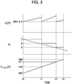
- FIG. 3 is a graph showing changes in the charging voltage Vc, the number of charging units N C , and the total voltage V TOTAL during charging of the power storage device 1 according to the present invention.
- the horizontal axis of FIG. 3 represents an elapsed time from a charging start timing t0.
- the control unit 10 calculates the number N C of power storage units to be set to the charging mode among the plurality of power storage units included in the power storage device 1, and starts the series charging.
- the control unit 10 controls the charging voltage V C so that the charging voltage V C is equal to a voltage value obtained by adding a constant potential difference ⁇ V to the increasing total voltage V TOTAL , whereby the power storge units in the charging mode can be charged with a constant current.
- the control unit 10 sets, to the bypass mode, a power storage unit in which charging is most advanced (the unit voltage is high) among the first power storage unit BBU1 to the seventh power storage unit BBU7, and continues the series charging.
- the control unit 10 can promote equalization of the unit voltages by interchanging the modes of both the power storage units.
- the control unit 10 sets, to the bypass mode, two power storage units in which the charging is most advanced among the first power storage unit BBU1 to the seventh power storage unit BBU7, and continues the series charging.
- the control unit 10 After the timing t2, as in the case of the period from the timing t1 to the timing t2, the control unit 10 also controls such that the unit voltages are equalized by switching the power storage units set in the charging mode and the power storage units set in the bypass mode as the charging progresses. At this time, since the number of power storage units set in the bypass mode increases in the period from the timing t2 to the timing t3 as compared with the period from the timing t1 to the timing t2, the equalization control of the unit voltages can be performed more finely.
- the control unit 10 stops the charging on all the power storage units on the assumption that the power storage device 1 has fallen into a fully charged state.
- the charging on the first power storage unit BBU1 to the seventh power storage unit BBU7 is completed in a state where the difference in unit voltage among the power storage units is reduced as the series charging progresses and thus the unit voltages are equalized. Therefore, each power storage unit is suppressed from falling into an overcharged state, and has been charged until a rechargeable power capacity.
- the present embodiment has been described on the assumption that charging is started from a state where the total voltage V TOTAL has dropped to the discharge termination voltage V CUTOFF .
- the series charging is started, for example, from a state where the total voltage V TOTAL is 310 V
- charging is started from a state at the timing t1 of FIG. 3 in which the six power storage units are set to the charging mode.
- the control unit 10 controls the charge switches SW C and the bypass switches SW B to be set to OFF and controls the discharge switches SW D to be set to ON, thereby setting the first power storage unit BBU1 to the seventh power storage unit BBU7 to the discharge mode all at once.
- the power storage device 1 can immediately output the total voltage V TOTAL to the load 3, and can reduce the possibility that power being supplied to the load 3 may be interrupted momentarily.
- the power storage device 1 can equalize the unit voltages by sequentially setting the power storage units to the bypass mode in the series charging of the first power storage unit BBU1 to the seventh power storage unit BBU7. Further, the power storage device 1 can more finely equalize the unit voltages by increasing the number of power storage units to be set to the bypass mode as the series charging progresses.
- the power storage device 1 controls the number N C of the power storage units to be set to the charging mode so that the number N C is equal to a minimum natural number satisfying N C ⁇ V CUTOFF ⁇ N TOTAL /V TOTAL , whereby the power storage device 1 can increase the number of power storage units to be set to the bypass mode as early as possible and equalize the unit voltages more reliably while suppressing a charging time to be taken for full charge. Even when power outage occurs during charging, the power storage device 1 can suppress momentary interruption in the load 3 by setting the respective power storage units to the discharging mode all at once. Therefore, according to the power storage device 1 according to the present invention, when a plurality of power storage units connected in series is charged, it is possible to suppress reduction in the rechargeable power capacity while equalizing the capacities of the power storage units.
- a first aspect of the present invention is a power storage device comprising a plurality of power storage units connected in series, and a control unit for monitoring a unit voltage of each of the plurality of power storage units and controlling each of the plurality of power storage units, wherein each of the power storage units includes a power storage portion and a charge switch which are connected to each other in series between charge/discharge terminals, and a bypass switch providing a bypass between the charge/discharge terminals, and for the plurality of power storage units to be charged in series, the control unit individually sets a charging mode in which the power storage portion is charged with a constant current by controlling the bypass switch to be set to OFF while controlling the charge switch to be set to ON, and a bypass mode in which the charging of the power storage portion is stopped by controlling the bypass switch to be set to ON while controlling the charge switch to be set to OFF, thereby equalizing the unit voltages.
- the power storage device includes the plurality of power storage units connected in series, and these power storage units are charged in series by the control unit.
- the power storage portion and the charge switch are connected to each other in series between the charge/discharge terminals, and the bypass switch is provided so as to bypass between the charge/discharge terminals. Therefore, each power storage unit is set to the charging mode in which the power storage portion is charged by controlling the charge switch to be set to ON and controlling the bypass switch to be set to OFF. Further, each power storage unit is set to the bypass mode in which the power storage portion is bypassed by controlling the charge switch to be set to OFF and controlling the bypass switch to be set to ON.
- the control unit controls the charging voltage according to the voltage of the power storage unit set to the charging mode while individually setting each power storage unit to the charging mode or the bypass mode, whereby the unit voltages can be equalized while the respective power storage units are charged in series with a constant current. Therefore, the power storage device can reduce the possibility that only some of the power storage units may be overcharged, and can perform charging up to the upper limit of the power capacity of each power storage unit.
- the first aspect of the present invention in the charging of the plurality of power storage units connected in series, it is possible to suppress reduction in the rechargeable power capacity while equalizing the capacities of the power storage units.
- a second aspect of the present invention is an power storage device in which, in the foregoing first aspect of the present invention, the control unit increases the number of power storage units to be set to the bypass mode as the charging of the plurality of power storage units progresses.
- the power storage device in the series charging of the plurality of power storage units, can equalize the unit voltages more finely by increasing the number of power storage units to be set to the bypass mode as the state approaches a full charge state.
- a third aspect of the present invention is a power storage device in which, in the foregoing first or second aspect of the present invention, the control unit controls the number N C of the power storage units to be set to the charging mode so that the number N C is equal to a minimum natural number satisfying N C ⁇ V CUTOFF ⁇ N TOTAL /V TOTAL when a discharge termination voltage of the power storage unit is represented by V CUTOFF , a series connection number of the power storage units is represented by N TOTAL , and a total voltage of the plurality of power storage units is represented by V TOTAL .
- the time required for charging can be shortened by increasing the number of power storage units to be set to the charging mode. Further, the unit voltages can be more reliably equalized by increasing the number of power storage units to be set to the bypass mode. Therefore, the power storage device can perform series charging optimizing both the merits described above by controlling the number N C of the power storage units to be set to the charging mode based on the expression of N C ⁇ V CUTOFF ⁇ N TOTAL /V TOTAL .
- the power storage device can increase the number of power storage units to be set to the bypass mode as early as possible while suppressing a charging time to be taken for full charge, and can more reliably equalize the unit voltages.
- a fourth aspect of the present invention is a power storage device in which, in any one of the foregoing first to third aspects of the present invention, the power storage unit includes a discharge switch connected in parallel to the charge switch, and when power outage occurs during charging of the plurality of power storage units, for all the power storage units, the control unit controls the charge switches and the bypass switches to be set to OFF and controls the discharge switches to be set to ON.
- the power storage device can suppress momentary interruption in the load by setting the respective power storage units to the discharge mode all at once.
- a fifth aspect of the present invention is a charging method that charges a plurality of power storage units connected in series, and comprises a voltage monitoring step of monitoring a unit voltage of each of the plurality of power storage units, and a series charging step of performing series charging on each of the plurality of power storage units while equalizing the unit voltages by individually setting either a charging mode in which an internal power storage portion is charged with a constant current or a bypass mode in which the internal power storage portion is bypassed to stop charging.
- a charging mode or a bypass mode is individually set for each of the power storage units while monitoring the voltage of each unit.
- a charging voltage is controlled according to the voltage of the power storage unit set to the charging mode, whereby the unit voltages can be equalized while performing series charging on each power storage unit with a constant current.
- the charging method of the present invention can reduce the possibility that only some of the power storage units may be overcharged, and can perform charging up to the upper limit of the power capacity of each power storage unit. Therefore, according to the charging method according to the fifth aspect of the present invention, in the charging of the plurality of power storage units connected in series, the reduction in rechargeable power capacity can be suppressed while the capacities of the power storage units are equalized.
- a sixth aspect of the present invention is a charging method in which, in the foregoing fifth aspect of the present invention, the number of power storage units to be set to the bypass mode is increased as the charging of the plurality of power storage units progresses in the series charging step.
- the number of power storage units to be set to the bypass mode increases as the state approaches a full charge state, so that the unit voltages can be equalized more finely.
- a seventh aspect of the present invention is a charging method in which, in the foregoing fifth or sixth aspect of the present invention, the number N C of the power storage units to be set to the charging mode is controlled to be equal to a minimum natural number satisfying N C ⁇ V CUTOFF ⁇ N TOTAL /V TOTAL in the series charging step when a discharge termination voltage of the power storage unit is represented by V CUTOFF , a series connection number of the power storage units is represented by N TOTAL , and a total voltage of the plurality of power storage units is represented by V TOTAL .
- the time required for charging can be shortened by increasing the number of power storage units to be set to the charging mode. Further, the unit voltages can be more reliably equalized by increasing the number of power storage units to be set to the bypass mode. Therefore, it is possible to perform series charging optimizing both the merits by the charging method for controlling the number N C of the power storage units to be set to the charging mode based on the expression of N C ⁇ V CUTOFF ⁇ N TOTAL /V TOTAL .
- the number of power storage units to be set to the bypass mode can be increased as early as possible while suppressing the charging time to be taken for full charge, and the unit voltages can be equalized more reliably.
- An eighth aspect of the present invention is a charging method in which, in any one of the foregoing fifth to seventh aspects of the present invention, in the series charging step, when power outage occurs during charging of the plurality of power storage units, all the power storage units are set to a discharging mode in which charging of internal power storage portions thereof is stopped to discharge the power storage portions.
Landscapes
- Engineering & Computer Science (AREA)
- Power Engineering (AREA)
- Chemical & Material Sciences (AREA)
- Chemical Kinetics & Catalysis (AREA)
- Electrochemistry (AREA)
- General Chemical & Material Sciences (AREA)
- Manufacturing & Machinery (AREA)
- Charge And Discharge Circuits For Batteries Or The Like (AREA)
- Stand-By Power Supply Arrangements (AREA)
- Secondary Cells (AREA)
Abstract
Description
- The present invention relates to a power storage device and a charging method.
- A power storage system such as an uninterruptible power supply device can supply electric power to a load device for a certain period of time even during power outage, and thus it has been widely used as a backup power supply for BCP countermeasures in the event of a disaster, for example. In normal times when AC power is supplied from a commercial power source to a load device, the power storage system branches the AC power to receive power, and converts the received power into DC power, and then charges a storage battery by a charging circuit. When power outage occurs, the power storage system maintains power supply to the load device by converting the power charged in the storage battery into AC power with an inverter and supplying the AC power to the load device.
- The power storage system as described above can be easily managed by configuring the power storage system as a power storage unit including a plurality of storage batteries, and it is further adaptable to a load device requiring a high voltage by connecting a plurality of power storage units in series. However, in such a power storage system, a charging voltage is applied to the whole of the plurality of power storage units connected in series at the time of charging, and when variation occurs among respective unit voltages of the plurality of power storage units, from the viewpoint of preventing overcharging, it is necessary to terminate charging at the time point when any unit voltage has reached full charge. Therefore, the power storage system as described above may be restricted to perform charging and discharging with only a power capacity smaller than the originally designed capacity.
- In order to suppress the variation in unit voltage among the plurality of power storage units, a battery system is constructed in a prior art described in
Patent Document 1 by a storage battery group A including a plurality of storage batteries connected in series and one storage battery B having a lower capacity than the storage battery group A, which are connected in series. As a result, the prior art ofPatent Document 1 prevents all the storage batteries included in the storage battery group A from being overcharged and overdischarged by managing SOC (State of Charge) of the storage battery group A within a certain range. - Patent Document 1:
Japanese Patent Laid-Open No. 2010-9840 - However, the above-mentioned prior art is intended to suppress occurrence of overcharging and overdischarging by equalizing the SOCs of the plurality of storage batteries, but a configuration thereof for that purpose limits the power capacity which can be charged in the storage batteries included in the battery system.
- An object of the present invention, which has been made in view of such a situation, is to provide a power storage device capable of suppressing reduction in rechargeable power capacity while equalizing the capacities of a plurality of power storage units connected in series during charging of the plurality of power storage units, and a method of charging the power storage device.
- In order to achieve the above object, an aspect of the present invention is directed to a power storage device comprising: a plurality of power storage units connected in series; and a control unit for monitoring a unit voltage of each of the plurality of power storage units and controlling each of the plurality of power storage units, wherein each of the power storage units includes an power storage portion and a charge switch which are connected to each other in series between charge/discharge terminals, and a bypass switch providing a bypass between the charge/discharge terminals, and for the plurality of power storage units to be charged in series, the control unit individually sets a charging mode in which the power storage portion is charged with a constant current by controlling the bypass switch to be set to OFF while controlling the charge switch to be set to ON, and a bypass mode in which the charging of the power storage portion is stopped by controlling the bypass switch to be set to ON while controlling the charge switch to be set to OFF, thereby equalizing the unit voltages.
- According to the present invention, there can be provided a power storage device capable of suppressing reduction in rechargeable power capacity while equalizing capacities of a plurality of power storage units connected in series during charging of the plurality of power storage units, and a method of charging the power storage device.
-
-
FIG. 1 is a circuit diagram of a backup power supply using a power storage device according to the present invention. -
FIG. 2 is a circuit diagram showing a configuration of the power storage device according to the present invention. -
FIG. 3 is a graph showing changes in charging voltage, the number of charging units, and a total voltage during charging of the power storage device according to the present invention. - Embodiments of the present invention will be described hereunder in detail with reference to the drawings. Note that the present invention is not limited to the contents described below, and any modification and implementation may be made without changing the subject matter thereof. Further, all the drawings used for describing the embodiments schematically show components, and are subjected to partially emphasis, enlargement, reduction, or omission in order to deepen the understanding of the components. Therefore, the drawings may not accurately represent the scales, shapes and the like of the components.
-
FIG. 1 is a circuit diagram of a backup power supply using apower storage device 1 according to the present invention. More specifically,FIG. 1 is a circuit diagram illustrating the configuration of a backup power supply provided in a power supply path from acommercial power source 2 to aload 3. - As describing a detailed configuration later, the
power storage device 1 is a so-called uninterruptible power system (UPS) that can be charged with power supplied from thecommercial power source 2 and enables power supply to theload 3 to be continued by discharging under power outage of thecommercial power source 2. - In the present embodiment, power of AC100V output from the
commercial power source 2 is converted to DC380V in apower supply circuit 4, and supplied to aswitching circuit 5. In normal times when no power outage occurs, the power of DC380V supplied to theswitching circuit 5 is reconverted to AC100V in aninverter 6, and output to theload 3. - Further, the power of AC100V output from the
commercial power source 2 is converted into DC power in acharging circuit 7, and also converted into a voltage required by thepower storage device 1 to be used for charging thepower storage device 1. - When power outage occurs in the
commercial power source 2, thepower storage device 1 outputs DC power to theinverter 6 via theswitching circuit 5. As a result, the power of DC380V output from thepower storage device 1 is reconverted to AC100V in theinverter 6 and output to theload 3. In other words, theswitching circuit 5 outputs the power input from thepower supply circuit 4 to theinverter 6 in normal times when no power outage occurs, and outputs the power input from thepower storage device 1 to theinverter 6 when power outage occurs, whereby the power supply source is switched. - Note that the configuration of the backup power supply using the
power storage device 1 of the present invention is not limited to the circuit configuration described above, and various changes can be made depending on conditions such as applicable equipment, etc. - A configuration of the
power storage device 1 will be described in more detail.FIG. 2 is a circuit diagram showing the configuration of thepower storage device 1 according to the present invention. - The
power storage device 1 includes a first power storage unit BBU1 to a seventh power storage unit BBU7 which are connected in series, and acontrol unit 10. Here, a configuration including power storage units of the series connection number NTOTAL=7 is illustrated in the present embodiment. However, the number of power storage units included in thepower storage device 1 is not limited to this number, and the number is appropriately adjusted so as to obtain an output voltage required for theload 3. - The first power storage unit BBU1 has charge/discharge terminals T(-) and T(+) formed therein, and includes an power storage portion BAT and a charge switch SWC that are connected in series between the charge/discharge terminals in the first power storage unit BBU1. Further, the first power storage unit BBU1 includes a discharge switch SWD which is connected in parallel with the charge switch SWC. Further, the first power storage unit BBU1 has a bypass path formed between the charge/discharge terminals, and a bypass switch SWB is provided in the bypass path.
- Here, the power storage portion BAT is made up of a plurality of battery cells each made of, for example, a nickel metal hydrogen battery or a nickel cadmium battery, which are connected in series. Further, the charge switch SWC, the discharge switch SWD, and the bypass switch SWB are composed of switching elements operating at high speed, such as MOSFETs (Metal-Oxide-Semiconductor Field-Effect Transistors) and IGBTs (Insulated Gate Bipolar Transistors).
- The charge switch SWC is controlled to be set to ON, the discharge switch SWD is controlled to be set to OFF, and the bypass switch SWB is controlled to be set to OFF, whereby the first power storage unit BBU1 is set to a charging mode in which the power storage portion BAT is charged with a charging voltage applied between the charge/discharge terminals. Further, the charge switch SWC is controlled to be set to OFF, the discharge switch SWD is controlled to be set to ON, and the bypass switch SWB is controlled to be set to OFF, whereby the first power storage unit BBU1 is set to a discharging mode in which the voltage of the power storage portion BAT as a unit voltage is output between the charge/discharge terminals.
- Here, the configurations of a second power storage unit BBU2 to the seventh power storage unit BBU7 are the same as the configuration of the first power storage unit BBU1 described above, and thus detailed description thereof will be omitted.
- The
control unit 10 is a so-called BMS (Battery Management System) that includes, for example, a well-known microcomputer control circuit and controls charging/discharging of thepower storage device 1. When charging thepower storage device 1, thecontrol unit 10 receives power from thecharging circuit 7, and applies a charging voltage VC between the charge/discharge terminal T(-) of the first power storage unit BBU1 and the charge/discharge terminal T(+) of the seventh power storage unit BBU7. Further, when discharging thepower storage device 1, thecontrol unit 10 supplies theswitching circuit 5 with a total voltage VTOTAL between the charge/discharge terminal T(-) of the first power storage unit BBU1 and the charge/discharge terminal T(+) of the seventh power storage unit BBU7. - More specifically, the
control unit 10 is configured to be capable of monitoring the respective unit voltages of the first power storage unit BBU1 to the seventh power storage unit BBU7, and individually controlling the charge switch SWC, the discharge switch SWD, and the bypass switch SWB of each of the power storage units. - When charging the first power storage unit BBU1 to the seventh power storage unit BBU7 in series, the
control unit 10 can set a bypass mode in which charging for a specific power storage unit is stopped. More specifically, for example, when setting the first power storage unit BBU1 to the bypass mode, thecontrol unit 10 controls the charge switch SWC, the discharge switch SWD and the bypass switch SWB of the first power storage unit BBU1 to be set to OFF, OFF and ON respectively, whereby the charge/discharge terminals of the first power storage unit BBU1 are shortcircuited to prohibit the power storage portion BAT from being charged. In this case, in the series charging of the respective power storage units, the second power storage unit BBU2 to the seventh power storage unit BBU7 are charged, whereas the first power storage unit BBU1 is excluded from the series charging. - Subsequently, a charging method for serially charging the first power storage unit BBU1 to the seventh power storage unit BBU7 of the
power storage device 1 will be described. - The
power storage device 1 can arbitrarily set a timing of charging in a case where the total voltage VTOTAL, which is the total of the unit voltages of the first power storage unit BBU1 to the seventh power storage unit BBU7, drops to a predetermined threshold value or less, in a case of recovering from power outage, and the like. In the following description, it is assumed that charging is started from a state where the total voltage VTOTAL drops to a discharge termination voltage VCUTOFF. Further, the total voltage VTOTAL in the present embodiment will be described on the assumption that the discharge termination voltage VCUTOFF is 265 V and a charging upper limit voltage is 380 V. - Further, the
control unit 10 continuously monitors the voltage of each of the power storage portions BAT of the first power storage unit BBU1 to the seventh power storage unit BBU7 at least during charging of the power storage device 1 (voltage monitoring step). Further, thecontrol unit 10 performs the series charging of the respective power storage units while the number Nc of power storage units to be set to the charging mode is controlled to be equal to a minimum natural number satisfying NC≥VCUTOFF×NTOTAL/VTOTAL (series charging step) . -
FIG. 3 is a graph showing changes in the charging voltage Vc, the number of charging units NC, and the total voltage VTOTAL during charging of thepower storage device 1 according to the present invention. The horizontal axis ofFIG. 3 represents an elapsed time from a charging start timing t0. - At the charging start timing t0, the
control unit 10 calculates the number NC of power storage units to be set to the charging mode among the plurality of power storage units included in thepower storage device 1, and starts the series charging. Here, thepower storage device 1 sets all the power storage units to the charging mode and starts the series charging from VCUTOFF×NTOTAL/VTOTAL=7 because the discharge termination voltage VCUTOFF is equal to 265 V, the series connection number NTOTAL of power storage units is equal to 7, and the total voltage VTOTAL at the start time of charging is equal to 265 V. - When charging of the
power storage device 1 is started, the total voltage VTOTAL also increases as the charging progresses. Here, thecontrol unit 10 controls the charging voltage VC so that the charging voltage VC is equal to a voltage value obtained by adding a constant potential difference ΔV to the increasing total voltage VTOTAL, whereby the power storge units in the charging mode can be charged with a constant current. - When the total voltage VTOTAL has reached 310 V at a timing t1, the
control unit 10 sets the number NC of power storage units to be set to the charging mode to 6 from VCUTOFF×NTOTAL/VTOTAL=5.98, and sets the remaining one power storage unit to the bypass mode. At this time, in order to equalize the unit voltages of the power storage units, thecontrol unit 10 sets, to the bypass mode, a power storage unit in which charging is most advanced (the unit voltage is high) among the first power storage unit BBU1 to the seventh power storage unit BBU7, and continues the series charging. Further, since the number of power storage units to be set to the charging mode decreases, thecontrol unit 10 controls such that the charging voltage VC returns to the discharge termination voltage VCUTOFF=265 V again, and the charging voltage VC increases according to the total of the unit voltages of the power storage units set in the charging mode. - Here, when there is a power storage unit to be set to the bypass mode, the unit voltage of one of the power storage units in the charging mode and the unit voltage of the power storage unit in the bypass mode may be reversed as the charging progresses. In this case, the
control unit 10 can promote equalization of the unit voltages by interchanging the modes of both the power storage units. - When the total voltage VTOTAL has reached 371 V at a timing t2, the
control unit 10 sets the number NC of the power storage units to be set to the charging mode to 5 from VCUTOFF×NTOTAL/VTOTAL=5, and sets the remaining two power storage units to the bypass mode. At this time, in order to equalize the unit voltages of the power storage units, thecontrol unit 10 sets, to the bypass mode, two power storage units in which the charging is most advanced among the first power storage unit BBU1 to the seventh power storage unit BBU7, and continues the series charging. Further, since the number of power storage units to be set to the charging mode decreases, thecontrol unit 10 controls such that the charging voltage VC returns to the discharge termination voltage VCUTOFF=265 V again, and the charging voltage VC increases according to the total of the unit voltages of the power storage units set in the charging mode. - After the timing t2, as in the case of the period from the timing t1 to the timing t2, the
control unit 10 also controls such that the unit voltages are equalized by switching the power storage units set in the charging mode and the power storage units set in the bypass mode as the charging progresses. At this time, since the number of power storage units set in the bypass mode increases in the period from the timing t2 to the timing t3 as compared with the period from the timing t1 to the timing t2, the equalization control of the unit voltages can be performed more finely. - When the total voltage VTOTAL has reached 380 V, which is a charging upper limit voltage, at the timing t3, the
control unit 10 stops the charging on all the power storage units on the assumption that thepower storage device 1 has fallen into a fully charged state. As a result, the charging on the first power storage unit BBU1 to the seventh power storage unit BBU7 is completed in a state where the difference in unit voltage among the power storage units is reduced as the series charging progresses and thus the unit voltages are equalized. Therefore, each power storage unit is suppressed from falling into an overcharged state, and has been charged until a rechargeable power capacity. - Here, the present embodiment has been described on the assumption that charging is started from a state where the total voltage VTOTAL has dropped to the discharge termination voltage VCUTOFF. However, when the series charging is started, for example, from a state where the total voltage VTOTAL is 310 V, charging is started from a state at the timing t1 of
FIG. 3 in which the six power storage units are set to the charging mode. - When power outage occurs during series charging, for all the power storage units, the
control unit 10 controls the charge switches SWC and the bypass switches SWB to be set to OFF and controls the discharge switches SWD to be set to ON, thereby setting the first power storage unit BBU1 to the seventh power storage unit BBU7 to the discharge mode all at once. As a result, even when power outage occurs during charging, thepower storage device 1 can immediately output the total voltage VTOTAL to theload 3, and can reduce the possibility that power being supplied to theload 3 may be interrupted momentarily. - As described above, the
power storage device 1 according to the present invention can equalize the unit voltages by sequentially setting the power storage units to the bypass mode in the series charging of the first power storage unit BBU1 to the seventh power storage unit BBU7. Further, thepower storage device 1 can more finely equalize the unit voltages by increasing the number of power storage units to be set to the bypass mode as the series charging progresses. Still further, thepower storage device 1 controls the number NC of the power storage units to be set to the charging mode so that the number NC is equal to a minimum natural number satisfying NC≥VCUTOFF×NTOTAL/VTOTAL, whereby thepower storage device 1 can increase the number of power storage units to be set to the bypass mode as early as possible and equalize the unit voltages more reliably while suppressing a charging time to be taken for full charge. Even when power outage occurs during charging, thepower storage device 1 can suppress momentary interruption in theload 3 by setting the respective power storage units to the discharging mode all at once. Therefore, according to thepower storage device 1 according to the present invention, when a plurality of power storage units connected in series is charged, it is possible to suppress reduction in the rechargeable power capacity while equalizing the capacities of the power storage units. - A first aspect of the present invention is a power storage device comprising a plurality of power storage units connected in series, and a control unit for monitoring a unit voltage of each of the plurality of power storage units and controlling each of the plurality of power storage units, wherein each of the power storage units includes a power storage portion and a charge switch which are connected to each other in series between charge/discharge terminals, and a bypass switch providing a bypass between the charge/discharge terminals, and for the plurality of power storage units to be charged in series, the control unit individually sets a charging mode in which the power storage portion is charged with a constant current by controlling the bypass switch to be set to OFF while controlling the charge switch to be set to ON, and a bypass mode in which the charging of the power storage portion is stopped by controlling the bypass switch to be set to ON while controlling the charge switch to be set to OFF, thereby equalizing the unit voltages.
- The power storage device includes the plurality of power storage units connected in series, and these power storage units are charged in series by the control unit. Here, in each power storage unit, the power storage portion and the charge switch are connected to each other in series between the charge/discharge terminals, and the bypass switch is provided so as to bypass between the charge/discharge terminals. Therefore, each power storage unit is set to the charging mode in which the power storage portion is charged by controlling the charge switch to be set to ON and controlling the bypass switch to be set to OFF. Further, each power storage unit is set to the bypass mode in which the power storage portion is bypassed by controlling the charge switch to be set to OFF and controlling the bypass switch to be set to ON.
- The control unit controls the charging voltage according to the voltage of the power storage unit set to the charging mode while individually setting each power storage unit to the charging mode or the bypass mode, whereby the unit voltages can be equalized while the respective power storage units are charged in series with a constant current. Therefore, the power storage device can reduce the possibility that only some of the power storage units may be overcharged, and can perform charging up to the upper limit of the power capacity of each power storage unit.
- As a result, according to the first aspect of the present invention, in the charging of the plurality of power storage units connected in series, it is possible to suppress reduction in the rechargeable power capacity while equalizing the capacities of the power storage units.
- A second aspect of the present invention is an power storage device in which, in the foregoing first aspect of the present invention, the control unit increases the number of power storage units to be set to the bypass mode as the charging of the plurality of power storage units progresses.
- According to the second aspect of the present invention, in the series charging of the plurality of power storage units, the power storage device can equalize the unit voltages more finely by increasing the number of power storage units to be set to the bypass mode as the state approaches a full charge state.
- A third aspect of the present invention is a power storage device in which, in the foregoing first or second aspect of the present invention, the control unit controls the number NC of the power storage units to be set to the charging mode so that the number NC is equal to a minimum natural number satisfying NC≥VCUTOFF×NTOTAL/VTOTAL when a discharge termination voltage of the power storage unit is represented by VCUTOFF, a series connection number of the power storage units is represented by NTOTAL, and a total voltage of the plurality of power storage units is represented by VTOTAL.
- In the series charging of the plurality of power storage units, the time required for charging can be shortened by increasing the number of power storage units to be set to the charging mode. Further, the unit voltages can be more reliably equalized by increasing the number of power storage units to be set to the bypass mode. Therefore, the power storage device can perform series charging optimizing both the merits described above by controlling the number NC of the power storage units to be set to the charging mode based on the expression of NC≥VCUTOFF×NTOTAL/VTOTAL.
- As a result, according to the third aspect of the present invention, the power storage device can increase the number of power storage units to be set to the bypass mode as early as possible while suppressing a charging time to be taken for full charge, and can more reliably equalize the unit voltages.
- A fourth aspect of the present invention is a power storage device in which, in any one of the foregoing first to third aspects of the present invention, the power storage unit includes a discharge switch connected in parallel to the charge switch, and when power outage occurs during charging of the plurality of power storage units, for all the power storage units, the control unit controls the charge switches and the bypass switches to be set to OFF and controls the discharge switches to be set to ON.
- According to the fourth aspect of the present invention, even when power outage occurs during charging, the power storage device can suppress momentary interruption in the load by setting the respective power storage units to the discharge mode all at once.
- A fifth aspect of the present invention is a charging method that charges a plurality of power storage units connected in series, and comprises a voltage monitoring step of monitoring a unit voltage of each of the plurality of power storage units, and a series charging step of performing series charging on each of the plurality of power storage units while equalizing the unit voltages by individually setting either a charging mode in which an internal power storage portion is charged with a constant current or a bypass mode in which the internal power storage portion is bypassed to stop charging.
- In the charging method according to the fifth aspect of the present invention, when the plurality of power storage units is charged in series, a charging mode or a bypass mode is individually set for each of the power storage units while monitoring the voltage of each unit. At this time, a charging voltage is controlled according to the voltage of the power storage unit set to the charging mode, whereby the unit voltages can be equalized while performing series charging on each power storage unit with a constant current. As a result, the charging method of the present invention can reduce the possibility that only some of the power storage units may be overcharged, and can perform charging up to the upper limit of the power capacity of each power storage unit. Therefore, according to the charging method according to the fifth aspect of the present invention, in the charging of the plurality of power storage units connected in series, the reduction in rechargeable power capacity can be suppressed while the capacities of the power storage units are equalized.
- A sixth aspect of the present invention is a charging method in which, in the foregoing fifth aspect of the present invention, the number of power storage units to be set to the bypass mode is increased as the charging of the plurality of power storage units progresses in the series charging step.
- According to the charging method of the sixth aspect of the present invention, in the series charging of the plurality of power storage units, the number of power storage units to be set to the bypass mode increases as the state approaches a full charge state, so that the unit voltages can be equalized more finely.
- A seventh aspect of the present invention is a charging method in which, in the foregoing fifth or sixth aspect of the present invention, the number NC of the power storage units to be set to the charging mode is controlled to be equal to a minimum natural number satisfying NC≥VCUTOFF×NTOTAL/VTOTAL in the series charging step when a discharge termination voltage of the power storage unit is represented by VCUTOFF, a series connection number of the power storage units is represented by NTOTAL, and a total voltage of the plurality of power storage units is represented by VTOTAL.
- In the series charging of the plurality of power storage units, the time required for charging can be shortened by increasing the number of power storage units to be set to the charging mode. Further, the unit voltages can be more reliably equalized by increasing the number of power storage units to be set to the bypass mode. Therefore, it is possible to perform series charging optimizing both the merits by the charging method for controlling the number NC of the power storage units to be set to the charging mode based on the expression of NC≥VCUTOFF×NTOTAL/VTOTAL.
- As a result, according to the charging method of the seventh aspect of the present invention, the number of power storage units to be set to the bypass mode can be increased as early as possible while suppressing the charging time to be taken for full charge, and the unit voltages can be equalized more reliably.
- An eighth aspect of the present invention is a charging method in which, in any one of the foregoing fifth to seventh aspects of the present invention, in the series charging step, when power outage occurs during charging of the plurality of power storage units, all the power storage units are set to a discharging mode in which charging of internal power storage portions thereof is stopped to discharge the power storage portions.
- According to the charging method of the eighth aspect of the present invention, even when power outage occurs during charging, a momentary interruption in a load can be suppressed by setting the respective power storage units to the discharging mode all at once.
-
- 1 power storage device
- 2 commercial power source
- 3 load
- 10 control unit
- BBU1 to BBU7 first power storage unit to seventh power storage unit
- BAT power storage portion
- SWC charge switch
- SWD discharge switch
- SWB bypass switch
- T(+), T(-) charge/discharge terminal
Claims (8)
- A power storage device comprising:a plurality of power storage units connected in series; anda control unit for monitoring a unit voltage of each of the plurality of power storage units and controlling each of the plurality of power storage units, wherein each of the power storage units includes a power storage portion and a charge switch which are connected to each other in series between charge/discharge terminals, and a bypass switch providing a bypass between the charge/discharge terminals, andfor the plurality of power storage units to be charged in series, the control unit individually sets a charging mode in which the power storage portion is charged with a constant current by controlling the bypass switch to be set to OFF while controlling the charge switch to be set to ON, and a bypass mode in which the charging of the power storage portion is stopped by controlling the bypass switch to be set to ON while controlling the charge switch to be set to OFF, thereby equalizing the unit voltages.
- The power storage device according to claim 1,
wherein the control unit increases a number of the power storage units to be set to the bypass mode as the charging of the plurality of power storage units progresses. - The power storage device according to claim 1 or 2, wherein the control unit controls a number NC of the power storage units to be set to the charging mode so that the number NC is equal to a minimum natural number satisfying NC≥VCUTOFF×NTOTAL/VTOTAL when a discharge termination voltage of the power storage unit is represented by VCUTOFF, a series connection number of the power storage units is represented by NTOTAL, and a total voltage of the plurality of power storage units is represented by VTOTAL.
- The power storage device according to any one of claims 1 to 3, wherein the power storage unit includes a discharge switch connected in parallel to the charge switch, and when power outage occurs during charging of the plurality of power storage units, for all the power storage units, the control unit controls the charge switches and the bypass switches to be set to OFF and controls the discharge switches to be set to ON.
- A charging method for charging a plurality of power storage units connected in series, comprising:a voltage monitoring step of monitoring a unit voltage of each of the plurality of power storage units; anda series charging step of performing series charging on each of the plurality of power storage units while equalizing the unit voltages by individually setting either a charging mode in which an internal power storage portion is charged with a constant current or a bypass mode in which the internal power storage portion is bypassed to stop charging.
- The charging method according to claim 5, wherein, in the series charging step, a number of the power storage units to be set to the bypass mode is increased as the charging of the plurality of power storage units progresses.
- The charging method according to claim 5 or 6, wherein, in the series charging step, a number NC of the power storage units to be set to the charging mode is controlled to be equal to a minimum natural number satisfying NC≥VCUTOFF×NTOTAL/VTOTAL when a discharge termination voltage of the power storage unit is represented by VCUTOFF, a series connection number of the power storage units is represented by NTOTAL, and a total voltage of the plurality of power storage units is represented by VTOTAL.
- The charging method according to any one of claims 5 to 7, wherein, in the series charging step, when power outage occurs during charging of the plurality of power storage units, all the power storage units are set to a discharging mode in which charging of internal power storage portions thereof is stopped to discharge the power storage portions.
Applications Claiming Priority (2)
| Application Number | Priority Date | Filing Date | Title |
|---|---|---|---|
| JP2018168047A JP7044671B2 (en) | 2018-09-07 | 2018-09-07 | Power storage device and charging method |
| PCT/JP2019/023595 WO2020049824A1 (en) | 2018-09-07 | 2019-06-14 | Electricity storage device and charging method |
Publications (2)
| Publication Number | Publication Date |
|---|---|
| EP3849046A1 true EP3849046A1 (en) | 2021-07-14 |
| EP3849046A4 EP3849046A4 (en) | 2022-05-18 |
Family
ID=69721764
Family Applications (1)
| Application Number | Title | Priority Date | Filing Date |
|---|---|---|---|
| EP19857029.3A Pending EP3849046A4 (en) | 2018-09-07 | 2019-06-14 | ELECTRICITY STORAGE DEVICE AND CHARGING METHOD |
Country Status (5)
| Country | Link |
|---|---|
| US (1) | US20210344204A1 (en) |
| EP (1) | EP3849046A4 (en) |
| JP (1) | JP7044671B2 (en) |
| CN (1) | CN112655131B (en) |
| WO (1) | WO2020049824A1 (en) |
Cited By (2)
| Publication number | Priority date | Publication date | Assignee | Title |
|---|---|---|---|---|
| WO2022003368A3 (en) * | 2020-07-02 | 2022-03-17 | Arrival Ltd | A battery module and a vehicle |
| EP4175115A1 (en) * | 2021-11-02 | 2023-05-03 | FDK Corporation | Charging method and backup power supply device |
Families Citing this family (10)
| Publication number | Priority date | Publication date | Assignee | Title |
|---|---|---|---|---|
| SE544262C2 (en) * | 2020-07-01 | 2022-03-22 | Scania Cv Ab | A method for connecting one or more electric battery units to an electrical system |
| JP6861923B1 (en) | 2020-11-11 | 2021-04-21 | 三菱電機株式会社 | Power storage device and power system stabilization system |
| CN113629821B (en) * | 2021-09-02 | 2024-04-12 | 阳光电源股份有限公司 | Energy storage system and control method thereof |
| CN113629822B (en) * | 2021-09-02 | 2024-08-13 | 阳光电源股份有限公司 | Energy storage system and control method thereof |
| JP7773343B2 (en) * | 2021-11-05 | 2025-11-19 | Fdk株式会社 | Battery bank unit, remaining charge time calculation method, and remaining charge time calculation program |
| JP7773342B2 (en) | 2021-11-05 | 2025-11-19 | Fdk株式会社 | Battery bank unit, remaining charge time calculation method, and remaining charge time calculation program |
| KR102646533B1 (en) * | 2022-06-29 | 2024-03-13 | 주식회사 모큐라텍 | Battery cell charging/discharging device using SoH information and the method thereof |
| JP2024067630A (en) * | 2022-11-07 | 2024-05-17 | プライムアースEvエナジー株式会社 | Energy Storage System |
| WO2025046905A1 (en) | 2023-09-01 | 2025-03-06 | 三菱電機株式会社 | Electricity storage system, electricity storage unit, power supply system, and electricity storage system control method |
| JP7802115B1 (en) | 2024-06-27 | 2026-01-19 | シャープ株式会社 | Secondary Battery System |
Family Cites Families (10)
| Publication number | Priority date | Publication date | Assignee | Title |
|---|---|---|---|---|
| JP2000014042A (en) * | 1998-06-19 | 2000-01-14 | Kokusai Electric Co Ltd | Uninterruptible power system |
| CN101682091B (en) * | 2007-06-08 | 2012-07-25 | 松下电器产业株式会社 | Power supply system and battery pack control method |
| JP2010009840A (en) * | 2008-06-25 | 2010-01-14 | Panasonic Corp | Battery pack and battery system equipped with it |
| JP5440918B2 (en) * | 2009-09-02 | 2014-03-12 | 独立行政法人 宇宙航空研究開発機構 | Power storage device with balance circuit |
| US20130038289A1 (en) * | 2010-02-20 | 2013-02-14 | Lawrence Tze-Leung Tse | Battery-cell converter systems |
| JP5012962B2 (en) * | 2010-06-14 | 2012-08-29 | トヨタ自動車株式会社 | Vehicle power control device |
| FR2976743A1 (en) * | 2011-06-17 | 2012-12-21 | Commissariat Energie Atomique | METHOD FOR MANAGING AND DIAGNOSING A BATTERY |
| DE102012201602B4 (en) * | 2012-02-03 | 2023-03-02 | Robert Bosch Gmbh | Method and control device for adjusting a current flowing through a battery string |
| JP5981777B2 (en) * | 2012-06-12 | 2016-08-31 | 旭化成株式会社 | Charging system and charging method |
| US11264810B2 (en) * | 2019-03-21 | 2022-03-01 | StoreDot Ltd. | Balancing charging of lithium ion batteries by a switching circuitry |
-
2018
- 2018-09-07 JP JP2018168047A patent/JP7044671B2/en active Active
-
2019
- 2019-06-14 CN CN201980057989.0A patent/CN112655131B/en active Active
- 2019-06-14 EP EP19857029.3A patent/EP3849046A4/en active Pending
- 2019-06-14 WO PCT/JP2019/023595 patent/WO2020049824A1/en not_active Ceased
- 2019-06-14 US US17/268,912 patent/US20210344204A1/en not_active Abandoned
Cited By (3)
| Publication number | Priority date | Publication date | Assignee | Title |
|---|---|---|---|---|
| WO2022003368A3 (en) * | 2020-07-02 | 2022-03-17 | Arrival Ltd | A battery module and a vehicle |
| EP4175115A1 (en) * | 2021-11-02 | 2023-05-03 | FDK Corporation | Charging method and backup power supply device |
| US12580410B2 (en) | 2021-11-02 | 2026-03-17 | Fdk Corporation | Charging method and backup power supply device |
Also Published As
| Publication number | Publication date |
|---|---|
| CN112655131A (en) | 2021-04-13 |
| JP2020043653A (en) | 2020-03-19 |
| EP3849046A4 (en) | 2022-05-18 |
| US20210344204A1 (en) | 2021-11-04 |
| WO2020049824A1 (en) | 2020-03-12 |
| CN112655131B (en) | 2023-11-03 |
| JP7044671B2 (en) | 2022-03-30 |
Similar Documents
| Publication | Publication Date | Title |
|---|---|---|
| US20210344204A1 (en) | Power storage device and charging method | |
| EP3506451B1 (en) | Quick charging method for series battery pack, and related device | |
| US8947052B2 (en) | Charge-discharge control circuit, semiconductor integrated circuit, method of controlling charging and discharging | |
| US8476869B2 (en) | Battery voltage equalizer circuit and method for using the same | |
| US7928691B2 (en) | Method and system for cell equalization with isolated charging sources | |
| US9225191B2 (en) | Circuit and method for voltage equalization in large batteries | |
| EP2996217B1 (en) | Power supply apparatus | |
| US20090267565A1 (en) | Method and system for cell equalization with charging sources and shunt regulators | |
| JP5916429B2 (en) | Battery pack control system and battery pack control method | |
| KR20150142673A (en) | Accumulator battery management system | |
| KR20220121601A (en) | A method for balancing modules and a battery system providing the method | |
| JP7659526B2 (en) | Energy Storage System | |
| JP6214131B2 (en) | Battery pack charging system and battery pack charging method | |
| JP2000092737A (en) | Device for charging secondary battery | |
| EP3772153B1 (en) | Battery protection system | |
| CN117791788A (en) | Battery modules, energy storage systems and battery module control methods that can balance power | |
| JP5541682B2 (en) | Lithium-ion battery charging system and charging method | |
| US11462927B2 (en) | Method, rated voltage adjusting device, and electric storage device | |
| CA3172502A1 (en) | Charging method and backup power supply device | |
| US11742685B2 (en) | Charger and charging method | |
| JP2009219336A (en) | Dc power system and its charging method | |
| JP7644548B1 (en) | Power supply device and power supply control method | |
| JP6647662B1 (en) | Battery pack unit and cell balance adjustment method | |
| CN118739489A (en) | Energy storage device and energy storage method suitable for wind power and photovoltaic power generation | |
| Pham et al. | A Cell-to-Cell Fast Balancing Circuit for Lithium-Ion Battery Module |
Legal Events
| Date | Code | Title | Description |
|---|---|---|---|
| STAA | Information on the status of an ep patent application or granted ep patent |
Free format text: STATUS: THE INTERNATIONAL PUBLICATION HAS BEEN MADE |
|
| PUAI | Public reference made under article 153(3) epc to a published international application that has entered the european phase |
Free format text: ORIGINAL CODE: 0009012 |
|
| STAA | Information on the status of an ep patent application or granted ep patent |
Free format text: STATUS: REQUEST FOR EXAMINATION WAS MADE |
|
| 17P | Request for examination filed |
Effective date: 20210303 |
|
| AK | Designated contracting states |
Kind code of ref document: A1 Designated state(s): AL AT BE BG CH CY CZ DE DK EE ES FI FR GB GR HR HU IE IS IT LI LT LU LV MC MK MT NL NO PL PT RO RS SE SI SK SM TR |
|
| DAV | Request for validation of the european patent (deleted) | ||
| DAX | Request for extension of the european patent (deleted) | ||
| A4 | Supplementary search report drawn up and despatched |
Effective date: 20220420 |
|
| RIC1 | Information provided on ipc code assigned before grant |
Ipc: H02J 7/00 20060101ALI20220412BHEP Ipc: H01M 50/51 20210101ALI20220412BHEP Ipc: H01M 10/48 20060101ALI20220412BHEP Ipc: H01M 10/44 20060101ALI20220412BHEP Ipc: H02J 9/06 20060101ALI20220412BHEP Ipc: H02J 7/02 20160101AFI20220412BHEP |
|
| P01 | Opt-out of the competence of the unified patent court (upc) registered |
Effective date: 20230509 |
|
| RIC1 | Information provided on ipc code assigned before grant |
Ipc: H02J 7/02 20160101AFI20260325BHEP Ipc: H02J 9/06 20060101ALI20260325BHEP Ipc: H01M 10/44 20060101ALI20260325BHEP Ipc: H01M 10/48 20060101ALI20260325BHEP Ipc: H01M 50/51 20210101ALI20260325BHEP Ipc: H02J 7/54 20260101ALI20260325BHEP Ipc: H02J 7/80 20260101ALI20260325BHEP |
|
| GRAP | Despatch of communication of intention to grant a patent |
Free format text: ORIGINAL CODE: EPIDOSNIGR1 |
|
| STAA | Information on the status of an ep patent application or granted ep patent |
Free format text: STATUS: GRANT OF PATENT IS INTENDED |