EP3848643A1 - Gas conditioner - Google Patents
Gas conditioner Download PDFInfo
- Publication number
- EP3848643A1 EP3848643A1 EP19862416.5A EP19862416A EP3848643A1 EP 3848643 A1 EP3848643 A1 EP 3848643A1 EP 19862416 A EP19862416 A EP 19862416A EP 3848643 A1 EP3848643 A1 EP 3848643A1
- Authority
- EP
- European Patent Office
- Prior art keywords
- gas
- resin
- water
- channel
- resin member
- Prior art date
- Legal status (The legal status is an assumption and is not a legal conclusion. Google has not performed a legal analysis and makes no representation as to the accuracy of the status listed.)
- Ceased
Links
- 239000011347 resin Substances 0.000 claims abstract description 118
- 229920005989 resin Polymers 0.000 claims abstract description 118
- XLYOFNOQVPJJNP-UHFFFAOYSA-N water Substances O XLYOFNOQVPJJNP-UHFFFAOYSA-N 0.000 claims abstract description 80
- 239000011796 hollow space material Substances 0.000 claims abstract description 10
- 230000035699 permeability Effects 0.000 claims abstract description 5
- 238000004378 air conditioning Methods 0.000 claims description 17
- 230000002093 peripheral effect Effects 0.000 claims description 15
- 239000000463 material Substances 0.000 claims description 8
- 239000007769 metal material Substances 0.000 claims description 6
- 239000007789 gas Substances 0.000 description 111
- MYMOFIZGZYHOMD-UHFFFAOYSA-N Dioxygen Chemical compound O=O MYMOFIZGZYHOMD-UHFFFAOYSA-N 0.000 description 52
- 229910001882 dioxygen Inorganic materials 0.000 description 52
- CBENFWSGALASAD-UHFFFAOYSA-N Ozone Chemical compound [O-][O+]=O CBENFWSGALASAD-UHFFFAOYSA-N 0.000 description 20
- 238000000034 method Methods 0.000 description 12
- 239000002994 raw material Substances 0.000 description 6
- 238000013459 approach Methods 0.000 description 5
- 230000000903 blocking effect Effects 0.000 description 4
- 239000004065 semiconductor Substances 0.000 description 4
- 238000004519 manufacturing process Methods 0.000 description 3
- CURLTUGMZLYLDI-UHFFFAOYSA-N Carbon dioxide Chemical compound O=C=O CURLTUGMZLYLDI-UHFFFAOYSA-N 0.000 description 2
- 238000007791 dehumidification Methods 0.000 description 2
- 238000003466 welding Methods 0.000 description 2
- IJGRMHOSHXDMSA-UHFFFAOYSA-N Atomic nitrogen Chemical compound N#N IJGRMHOSHXDMSA-UHFFFAOYSA-N 0.000 description 1
- YCKRFDGAMUMZLT-UHFFFAOYSA-N Fluorine atom Chemical compound [F] YCKRFDGAMUMZLT-UHFFFAOYSA-N 0.000 description 1
- 230000004308 accommodation Effects 0.000 description 1
- 229910002092 carbon dioxide Inorganic materials 0.000 description 1
- 239000001569 carbon dioxide Substances 0.000 description 1
- 230000001143 conditioned effect Effects 0.000 description 1
- 238000010586 diagram Methods 0.000 description 1
- 229910001873 dinitrogen Inorganic materials 0.000 description 1
- 229920000840 ethylene tetrafluoroethylene copolymer Polymers 0.000 description 1
- 229910052731 fluorine Inorganic materials 0.000 description 1
- 239000011737 fluorine Substances 0.000 description 1
- 239000013505 freshwater Substances 0.000 description 1
- 239000012212 insulator Substances 0.000 description 1
- 238000002844 melting Methods 0.000 description 1
- 230000008018 melting Effects 0.000 description 1
- 229920009441 perflouroethylene propylene Polymers 0.000 description 1
- 229920011301 perfluoro alkoxyl alkane Polymers 0.000 description 1
- 239000004810 polytetrafluoroethylene Substances 0.000 description 1
- 229920001343 polytetrafluoroethylene Polymers 0.000 description 1
- 230000002035 prolonged effect Effects 0.000 description 1
- 239000007787 solid Substances 0.000 description 1
- 239000008399 tap water Substances 0.000 description 1
- 235000020679 tap water Nutrition 0.000 description 1
Images

Classifications
-
- F—MECHANICAL ENGINEERING; LIGHTING; HEATING; WEAPONS; BLASTING
- F24—HEATING; RANGES; VENTILATING
- F24F—AIR-CONDITIONING; AIR-HUMIDIFICATION; VENTILATION; USE OF AIR CURRENTS FOR SCREENING
- F24F3/00—Air-conditioning systems in which conditioned primary air is supplied from one or more central stations to distributing units in the rooms or spaces where it may receive secondary treatment; Apparatus specially designed for such systems
- F24F3/12—Air-conditioning systems in which conditioned primary air is supplied from one or more central stations to distributing units in the rooms or spaces where it may receive secondary treatment; Apparatus specially designed for such systems characterised by the treatment of the air otherwise than by heating and cooling
- F24F3/14—Air-conditioning systems in which conditioned primary air is supplied from one or more central stations to distributing units in the rooms or spaces where it may receive secondary treatment; Apparatus specially designed for such systems characterised by the treatment of the air otherwise than by heating and cooling by humidification; by dehumidification
-
- B—PERFORMING OPERATIONS; TRANSPORTING
- B01—PHYSICAL OR CHEMICAL PROCESSES OR APPARATUS IN GENERAL
- B01F—MIXING, e.g. DISSOLVING, EMULSIFYING OR DISPERSING
- B01F23/00—Mixing according to the phases to be mixed, e.g. dispersing or emulsifying
- B01F23/20—Mixing gases with liquids
- B01F23/21—Mixing gases with liquids by introducing liquids into gaseous media
-
- B—PERFORMING OPERATIONS; TRANSPORTING
- B01—PHYSICAL OR CHEMICAL PROCESSES OR APPARATUS IN GENERAL
- B01J—CHEMICAL OR PHYSICAL PROCESSES, e.g. CATALYSIS OR COLLOID CHEMISTRY; THEIR RELEVANT APPARATUS
- B01J19/00—Chemical, physical or physico-chemical processes in general; Their relevant apparatus
-
- C—CHEMISTRY; METALLURGY
- C01—INORGANIC CHEMISTRY
- C01B—NON-METALLIC ELEMENTS; COMPOUNDS THEREOF; METALLOIDS OR COMPOUNDS THEREOF NOT COVERED BY SUBCLASS C01C
- C01B13/00—Oxygen; Ozone; Oxides or hydroxides in general
- C01B13/10—Preparation of ozone
- C01B13/11—Preparation of ozone by electric discharge
-
- F—MECHANICAL ENGINEERING; LIGHTING; HEATING; WEAPONS; BLASTING
- F24—HEATING; RANGES; VENTILATING
- F24F—AIR-CONDITIONING; AIR-HUMIDIFICATION; VENTILATION; USE OF AIR CURRENTS FOR SCREENING
- F24F6/00—Air-humidification, e.g. cooling by humidification
- F24F6/02—Air-humidification, e.g. cooling by humidification by evaporation of water in the air
- F24F6/04—Air-humidification, e.g. cooling by humidification by evaporation of water in the air using stationary unheated wet elements
-
- F—MECHANICAL ENGINEERING; LIGHTING; HEATING; WEAPONS; BLASTING
- F24—HEATING; RANGES; VENTILATING
- F24F—AIR-CONDITIONING; AIR-HUMIDIFICATION; VENTILATION; USE OF AIR CURRENTS FOR SCREENING
- F24F3/00—Air-conditioning systems in which conditioned primary air is supplied from one or more central stations to distributing units in the rooms or spaces where it may receive secondary treatment; Apparatus specially designed for such systems
- F24F3/12—Air-conditioning systems in which conditioned primary air is supplied from one or more central stations to distributing units in the rooms or spaces where it may receive secondary treatment; Apparatus specially designed for such systems characterised by the treatment of the air otherwise than by heating and cooling
- F24F3/14—Air-conditioning systems in which conditioned primary air is supplied from one or more central stations to distributing units in the rooms or spaces where it may receive secondary treatment; Apparatus specially designed for such systems characterised by the treatment of the air otherwise than by heating and cooling by humidification; by dehumidification
- F24F2003/1435—Air-conditioning systems in which conditioned primary air is supplied from one or more central stations to distributing units in the rooms or spaces where it may receive secondary treatment; Apparatus specially designed for such systems characterised by the treatment of the air otherwise than by heating and cooling by humidification; by dehumidification comprising semi-permeable membrane
Definitions
- the present invention relates to a gas conditioner.
- An ozone generator that generates an ozone gas using an oxygen gas as a raw material is widely used for semiconductor manufacturing process and other processes.
- Patent Document 1 describes a generator including humidifiers (gas conditioner) that add water to an oxygen gas.
- humidifiers 4 are connected in series between an oxygen gas source and an ozonizer.
- An oxygen gas supplied from the oxygen gas source 2 is provided with a trace amount of water in the humidifiers 4, and then is supplied to the ozonizer 9.
- a moisture content in the oxygen gas supplied to the ozonizer 9 is adjusted to a target range (e.g., 0.05 to 40 ppm).
- a target range e.g., 0.05 to 40 ppm
- PATENT DOCUMENT 1 Japanese Patent No. 4166928
- the present invention has been made in view of such a problem and provides a gas conditioner capable of stably adjusting the amount of water added to a gas with a relatively simple configuration.
- a resin member constituted by a hermetic hollow material enclosing water is disposed in a gas channel.
- the present invention is directed to a gas conditioner configured to add water to a gas
- the gas conditioner includes a case forming a gas channel in which a gas is distributed, and a resin member disposed in the gas channel and having water permeability, and the resin member is constituted by a hermetic hollow material configured to enclose water.
- the resin member when the gas flowing in the gas channel flows around the hollow material, water in the resin member passes through the resin member and moves into the gas. In this manner, a trace amount of water can be added to the gas.
- the resin member is a hermetic hollow material configured to enclose water, and is not configured to be supplied with water as necessary. Thus, a pump or the like for transporting water is unnecessary, and the water temperature control is unnecessary. Accordingly, the configuration of the gas conditioner can be simplified. Since the amount of water added to the gas is extremely small, the rate of a decrease in water content in the resin member is extremely low. Accordingly, a period until water in the resin member runs out is sufficiently long.
- the resin member preferably includes a plurality of resin members
- the gas conditioner further preferably includes a support configured to support the plurality of resin members such that the plurality of resin members are allowed to be attached to and detached from the support.
- the number of resin members disposed in the gas channel can be easily changed.
- the amount of water added to the gas can be adjusted. Accordingly, an appropriate amount of water can be added to the gas in accordance with a gas flow rate and/or a target moisture concentration.
- the resin members are configured to be detachably attached to the support. Thus, the number of resin members can be easily changed and the resin members can be easily replaced.
- the resin member preferably includes a tubular peripheral wall portion, and a closing portion configured to close each end of the peripheral wall portion, and the c losing portion is preferably constituted by a welded portion of a resin material.
- the ends of the peripheral wall portion of the resin member are welded so that openings at the ends of the peripheral wall portion can be closed by the closing portions (welded portions). Accordingly, a hermetic hollow material enclosing water can be easily produced.
- the resin member preferably has a helical shape.
- the helical shape of the resin member can increase the volume and the surface area of the resin member. When the volume of the resin member increases, a period until water in the resin member runs out can be prolonged. When the surface area of the resin member increases, the amount of water capable of being added to a gas in one resin member can be increased. Thus, the resin member and the case can be miniaturized.
- the case is preferably made of a metal material and disposed in an air conditioning space where an air temperature is adjusted.
- the case In the case where the case is made of a metal material, the case has a relatively high thermal conductivity. Thus, the gas temperature in the case easily approaches the temperature around the case.
- the temperature around the case is adjustable by air conditioning, and thus, the gas temperature in the case can be indirectly adjusted. Since the temperature of water in the resin member is not controlled, this water temperature is dominated by a gas temperature in the gas channel and the temperature around the case. Accordingly, the water temperature in the resin member can be controlled by air conditioning so that the amount of water added to a gas can be thereby accurately adjusted.
- the case since the case is made of a metal material, leakage of a gas from the gas channel can be reduced.
- the present invention can provide a gas conditioner capable of stably adjusting the amount of water added to a gas with a relatively simple configuration.
- a gas conditioner according to an embodiment is applied to an ozone generator 10.
- the ozone generator 10 uses, as a raw material, an oxygen gas supplied from an oxygen gas source 5, and supplies an ozone gas generated by using the raw material to a predetermined supply target.
- the oxygen gas source 5 is, for example, an oxygen gas cylinder filled with an oxygen gas.
- the oxygen gas cylinder is filled with, for example, an oxygen gas having a high purity of 99.9999%.
- the oxygen gas has a moisture content of, for example, 50 ppb to 1000 ppb.
- the supply target of the ozone gas is, for example, semiconductor manufacturing facilities.
- the ozone generator 10 includes a dehumidifier 27 and a device body 20.
- the device body 20 includes, as main components, a humidifier 60, a discharge cell 28, a controller 50, and a power supply 51.
- the dehumidifier 27 may be omitted.
- the device body 20 includes a supply channel 30 as a main gas channel.
- the supply channel 30 includes a first channel 31 extending from the outside of the device body 20 to the humidifier 60, and a second channel 32 extending from the humidifier 60 to the discharge cell 28.
- An inflow end of the supply channel 30 is connected to the dehumidifier 27 connected to the oxygen gas source 5.
- An outflow end of the supply channel 30 is connected to the discharge cell 28.
- the dehumidifier 27 is an adsorption-type dehumidifier that selectively adsorbs moisture in an oxygen gas, for example.
- the dehumidifier 27 removes the moisture such that the moisture content of the oxygen gas becomes 10 ppb or less. That is, the moisture content of the oxygen gas that has passed through the dehumidifier 27 is substantially zero.
- the first channel 31 receives an oxygen gas from which moisture has been removed in the dehumidifier 27.
- the outflow end of the first channel 31 is connected to the humidifier 60 that adds water to the oxygen gas.
- the second channel 32 located downstream of the humidifier 60 is configured to cause an oxygen gas that has passed through the humidifier 60 to flow out. That is, the first channel 31 has the inflow end connected to the dehumidifier 27, and the outflow end connected to the humidifier 60. The second channel 32 has the inflow end connected to the humidifier 60, and the outflow end connected to the discharge cell 28.
- the humidifier 60 constitutes a gas conditioner that adds water to an oxygen gas.
- the humidifier 60 adds water in resin tubes 80 having water permeability to a gas.
- the oxygen gas to which water has been added in the humidifier 60 flows out to the second channel 32.
- the oxygen gas humidified by the humidifier 60 has a moisture content of, for example, 300 ppb to 2000 ppb.
- the first channel 31 has a flow control vale 43.
- the flow control vale 43 adjusts a flow rate of an oxygen gas that has flowed out of the dehumidifier 27 (i.e., a raw material gas to be supplied to the device body 20).
- the discharge cell 28 generates an ozone gas by using an oxygen gas that has flowed out of the second channel 32 as a raw material.
- the discharge cell 28 is a silent discharge-type ozone generator that generates an ozone gas by silent discharge, for example.
- the ozone gas generated by the discharge cell 28 is supplied to a predetermined supply target.
- the controller 50 is configured to control the power supply 51 and the flow control vale 43 individually.
- the controller 50 is constituted by using a microcomputer and a memory device (specifically a semiconductor memory) storing software for operating the microcomputer.
- the flow control vale 43 may be controlled by another controller outside the device body 20.
- the controller 50 adjusts an opening degree of the flow control vale 43 such that a flow rate of a raw material supplied to the device body 20 approaches a target flow rate.
- the controller 50 controls the power supply 51 such that the power supply 51 applies an alternating current to the discharge cell 28.
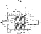
- the humidifier 60 includes a case 62 forming a gas channel 61 in which a gas flows, and a moisture adding unit 70 disposed in the gas channel 61.
- the case 62 is made of a metal material.
- the case 62 is made of a material having a high thermal conductivity, e.g., a stainless material.
- the case 62 includes a case body 63, a flange 64, and a blocking plate 65.
- the case body 63 has a tubular (strictly, cylindrical) shape whose ends are open.
- the flange 64 is attached to one axial end (left end) of the case body 63, and closes the opening at this end.
- the blocking plate 65 is attached to the other axial end (right end) of the case body 63, and closes the opening at this end.
- a first gas pipe 66 is connected to a center portion of the flange 64.
- a second gas pipe 67 is connected to a center portion of the blocking plate 65.
- the first gas pipe 66 constitutes a gas inflow pipe through which a gas in the first channel 31 flows into the gas channel 61
- the second gas pipe 67 constitutes a gas outflow pipe through which a gas in the gas channel 61 flows out to the second channel 32.
- the second gas pipe 67 may serve a gas inflow pipe with the first gas pipe 66 serving as a gas outflow pipe.
- the case 62 is disposed in an air conditioning space S.
- the air conditioning space S is provided in semiconductor manufacturing facilities to which an air conditioning apparatus is introduced.
- the air conditioning apparatus maintains an air temperature in the air conditioning space S at a target temperature.
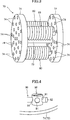
- the moisture adding unit 70 is disposed inside the case body 63. As illustrated in FIGS. 2 and 3 , the moisture adding unit 70 includes a first separator 71, a second separator 72, a strut 73, and a plurality of resin tubes 80 (resin members).
- the first separator 71 and the second separator 72 have circular plate shapes.
- the outer diameters of the first separator 71 and the second separator 72 are slightly smaller than the inner diameter of the case body 63. Accordingly, the first separator 71 and the second separator 72 are fitted in the case body 63.
- the first separator 71 is disposed close to the first gas pipe 66
- the second separator 72 is disposed close to the second gas pipe 67.
- a plurality of circular holes 74 are formed to penetrate each of the first separator 71 and the second separator 72 in an axial direction.
- the strut 73 is interposed between the first separator 71 and the second separator 72.
- the strut 73 is a long cylindrical columnar member. A longitudinal end of the strut 73 is fastened to a shaft center portion of the first separator 71. The other longitudinal end of the strut 73 is fastened to a shaft center portion of the second separator 72.
- a first header space 75 is formed between the flange 64 and the first separator 71.
- a second header space 76 is formed between the blocking plate 65 and the second separator 72.
- a humidifying channel 77 is formed between the first separator 71 and the second separator 72.
- the humidifying channel 77 is a part of the gas channel 61, and constitutes an accommodation chamber that accommodates the resin tubes 80.
- the moisture adding unit 70 includes three resin tubes 80.
- the number of the resin tubes 80 is merely an example.
- the number of the resin tubes 80 may be one or two, or four or more.
- the resin tubes 80 are made of a water-permeable resin material through which water is allowed to pass.
- the resin tubes 80 are made of a fluorine-based resin material such as PTFE, PFA, ETFE, or FEP.
- Each of the resin tubes 80 is constituted by a hermetic hollow material configured to enclose water.
- each of the resin tubes 80 has a helical shape. More specifically, each of the resin tubes 80 includes a helical peripheral wall portion 81, and a pair of closing portions 82 and 82 that close ends of the peripheral wall portion 81.
- the peripheral wall portion 81 has a helical shape that turns around an axis along a direction in which the first gas pipe 66 and the second gas pipe 67 extend. In other words, the peripheral wall portion 81 has a helical shape that forms a spiral along the inner peripheral surface of the case 62.
- the pair of closing portions 82 and 82 respectively closes openings at longitudinal ends of the peripheral wall portion 81.
- the pair of closing portions 82 and 82 is formed by melting opening edges of the peripheral wall portion 81 at the ends thereof with heat and then closing the openings. That is, the closing portions 82 constitute welded portions formed by welding the opening edges of the peripheral wall portion 81 at the ends thereof. In this manner, the resin tubes 80 enclosing water can be easily produced.
- the plurality of resin tubes 80 are allowed to be attached and detached to/from the first separator 71 and the second separator 72. That is, the first separator 71 and the second separator 72 constitute supports configured to support the plurality of resin tubes 80 such that the resin tubes 80 can be attached to and detached from the first and second separators 71 and 72.
- each of the first separator 71 and the second separator 72 includes a fixture 90 for fixing the resin tubes 80.
- the fixture 90 has a cylindrical columnar shape having a plurality of through holes 91 each extending radially.
- a proximal end portion of the fixture 90 has a male thread (not shown).
- the male thread of the fixture 90 is fastened to a screw hole (not shown) formed in each of the first separator 71 and the second separator 72, thereby fixing the fixture 90 to each of the separators 71 and 72.
- each resin tube 80 The outer diameter of an end portion of each resin tube 80 is slightly smaller than the diameter of the corresponding through hole 91 of the fixture 90.
- the end portion of the resin tube 80 is inserted in the through hole 91 of the fixture 90, thereby fixing the end portion of the resin tube 80 to the fixture 90.
- the ends of the resin tube 80 are individually fixed to the fixtures 90 so that the resin tube 80 is thereby held between the separators 71 and 72.
- the ends of each resin tube 80 are pulled out from the through holes 91 so that the resin tube 80 is thereby removed from the separators 71 and 72.
- an oxygen gas of the oxygen gas source 5 passes through the dehumidifier 27.
- a dehumidification process of removing moisture in the oxygen gas from the oxygen gas source 5 to 10 ppb or less is performed. Accordingly, even if a certain content of moisture is included in the oxygen gas of the oxygen gas source 5 or the moisture content of the oxygen gas varies, the moisture content of the oxygen gas subjected to the removal process becomes substantially zero.
- the oxygen gas having a moisture content of 10 ppb or less through the dehumidification process flows into the humidifier 60 from the first channel 31.
- a humidification process of adding water to the oxygen gas is performed (which will be described later in detail).
- the humidifier 60 is supplied with the oxygen gas having a moisture content of substantially zero through the dehumidifier 27. Accordingly, even when a moisture content of the oxygen gas supplied from the oxygen gas source 5 slightly varies, for example, the moisture content of the oxygen gas supplied to the humidifier 60 hardly varies (remains zero). Thus, external factors affecting humidifying capacity of the humidifier 60 decrease so that a variation in the moisture content of the oxygen gas supplied from the first channel 31 to the second channel 32 can be thereby reduced.
- the oxygen gas flows in the first gas pipe 66, and then flows into the first header space 75.
- the oxygen gas in the first header space 75 is branched into the plurality of holes 74 of the first separator 71, and then flows into the humidifying channel 77.
- the oxygen gas flows around the plurality of resin tubes 80. At this time, water in the resin tubes 80 passes through the resin tubes 80, and moves into the oxygen gas. Accordingly, a trace amount of water is added to the oxygen gas.
- the oxygen gas provided with water is branched into the plurality of holes 74 of the second separator 72, and then combined in the second header space 76.
- the oxygen gas of the second header space 76 flows in the second gas pipe 67, and then is sent to the second channel 32.
- the temperature of air in the air conditioning space S around the case 62 is adjusted by an air conditioning apparatus. Since the case 62 is made of a stainless material having a high thermal conductivity, the temperature of a gas flowing in the gas channel 61 approaches the temperature of air in the air conditioning space S.
- the resin tubes 80 are disposed in the gas channel 61 so that the water temperature in the resin tubes 80 thereby approaches the temperature of a gas flowing in the gas channel 61. Accordingly, the water temperature in the resin tubes 80 approaches the temperature of air in the air conditioning space S, and thus, can be controlled by the air conditioning apparatus.
- the water temperature in the resin tubes 80 does not vary significantly, and thus, a variation in the amount of water released into a gas due to such a variation in water temperature can be reduced.
- the amount of water released into the gas can be adjusted by changing the number of the resin tubes 80. Specifically, the amount of water added to the gas is increased by increasing the number of resin tubes 80 attached to the moisture adding unit 70. For example, in a case where the flow rate of a gas to be processed doubles or a target moisture content doubles, the number of resin tubes 80 is doubled. Accordingly, water in an amount in accordance with the gas flow rate or the target moisture content can be added to the gas simply by changing the number of resin tubes 80.
- a factor except for the number of resin tubes 80 may be changed.
- this factor include the thickness, length, size, shape, material, and water permeability of the resin tubes 80.
- Each of the resin tubes 80 according to this embodiment is constituted by a hermetic hollow material configured to enclose water.
- a pump for transporting water and a chiller unit for adjusting the temperature of water to be transported, for example, are unnecessary.
- the amount of water added to a gas can be stably adjusted with a simple configuration of the humidifier 60.
- the first separator 71 and the second separator 72 detachably support the plurality of resin tubes 80.
- the number of resin tubes 80 can be easily changed, and the amount of water to be released can be easily adjusted.
- the resin tubes 80 can be replaced easily.
- each of the resin tubes 80 have the closing portions 82 and 82 each formed by welding a resin.
- the resin tubes 80 enclosing water can be easily produced.
- the resin tubes 80 have helical shapes, the volume and the surface area of the resin tubes 80 can be easily enlarged.
- the volume of the resin tubes 80 increases, a period until water in the resin tubes 80 runs out becomes longer so that the frequency in replacing the resin tubes 80 can be reduced.
- the surface area of the resin tubes 80 increases, the amount of water capable of being added to a gas can be increased. Accordingly, the resin tubes 80, and further the case 62, can be miniaturized.
- the case 62 is made of a metal material, and is disposed in the air conditioning space S.
- the water temperature in the resin tubes 80 is dominated by the temperature in the air conditioning space S, and thus, the water temperature can be controlled as intended.
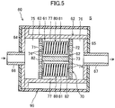
- the periphery of the case 62 may be (partially or entirely) covered with a heat insulator 95.
- a heat insulator 95 it is possible to reduce a change in the gas temperature of the gas channel 61 under the influence of the temperature around the case 62. Accordingly, the water temperature of the resin tubes 80 is dominated by the gas temperature of the gas channel 61.
- the water temperature of the resin tubes 80 can be controlled to be constant by using the temperature of a gas flowing in the gas channel 61.
- the resin member 80 is constituted by helical resin tubes.
- the resin member 80 may have any structure as long as the resin member 80 is a hermetic hollow material configured to enclose water.
- the resin member 80 may have a ring shape.
- a ring-shaped resin member 80 having a small diameter can be disposed inside a ring-shaped resin member 80 having a large diameter.
- the resin member 80 may have a rod shape, a flat-plate shape, an arc shape, or a rectangular solid shape, for example.
- a target gas of the gas conditioner 60 is an oxygen gas.
- the target gas is not limited to the oxygen gas, and may be other gases such as a nitrogen gas, a carbon dioxide gas, or air.
- Water to be added to a gas by the gas conditioner 60 may not be pure water, and may be water containing other components (e.g., fresh water or tap water).
- the humidifier 60 is disposed in the device body 20 in the embodiment, but may be disposed outside the device body 20.
- the present invention is useful for a gas conditioner.
Landscapes
- Chemical & Material Sciences (AREA)
- Organic Chemistry (AREA)
- Engineering & Computer Science (AREA)
- Inorganic Chemistry (AREA)
- Mechanical Engineering (AREA)
- General Engineering & Computer Science (AREA)
- Combustion & Propulsion (AREA)
- Chemical Kinetics & Catalysis (AREA)
- Air Humidification (AREA)
- Oxygen, Ozone, And Oxides In General (AREA)
- Physical Or Chemical Processes And Apparatus (AREA)
- Drying Of Gases (AREA)
- Separation Using Semi-Permeable Membranes (AREA)
- Air Filters, Heat-Exchange Apparatuses, And Housings Of Air-Conditioning Units (AREA)
Abstract
Description
- The present invention relates to a gas conditioner.
- An ozone generator that generates an ozone gas using an oxygen gas as a raw material is widely used for semiconductor manufacturing process and other processes.
- As an ozone generator of this type, Patent Document 1 describes a generator including humidifiers (gas conditioner) that add water to an oxygen gas. Specifically, in the ozone generator, humidifiers 4 are connected in series between an oxygen gas source and an ozonizer. An oxygen gas supplied from the oxygen gas source 2 is provided with a trace amount of water in the humidifiers 4, and then is supplied to the ozonizer 9. Accordingly, a moisture content in the oxygen gas supplied to the ozonizer 9 is adjusted to a target range (e.g., 0.05 to 40 ppm). In the manner described above, a trace amount of water is added to the oxygen gas so that a decrease in ozone concentration of a resulting ozone gas is reduced.
- PATENT DOCUMENT 1:
Japanese Patent No. 4166928 - In a gas conditioner as described in Patent Document 1, water to be added to a gas needs to be transported by, for example, pump. In the case of adding a trace amount of water to a gas by a gas conditioner, the amount of water supplied to the gas significantly changes with a variation in water temperature. For this reason, it is necessary to control the temperature of water to be transported. This necessity results in a problem of complicated configurations of a gas conditioner and ancillary equipment thereof.
- The present invention has been made in view of such a problem and provides a gas conditioner capable of stably adjusting the amount of water added to a gas with a relatively simple configuration.
- According to the present invention, to solve the problem, a resin member constituted by a hermetic hollow material enclosing water is disposed in a gas channel.
- Specifically, the present invention is directed to a gas conditioner configured to add water to a gas, and the gas conditioner includes a case forming a gas channel in which a gas is distributed, and a resin member disposed in the gas channel and having water permeability, and the resin member is constituted by a hermetic hollow material configured to enclose water.
- According to the present invention, when the gas flowing in the gas channel flows around the hollow material, water in the resin member passes through the resin member and moves into the gas. In this manner, a trace amount of water can be added to the gas. The resin member is a hermetic hollow material configured to enclose water, and is not configured to be supplied with water as necessary. Thus, a pump or the like for transporting water is unnecessary, and the water temperature control is unnecessary. Accordingly, the configuration of the gas conditioner can be simplified. Since the amount of water added to the gas is extremely small, the rate of a decrease in water content in the resin member is extremely low. Accordingly, a period until water in the resin member runs out is sufficiently long.
- In the gas conditioner, the resin member preferably includes a plurality of resin members, and the gas conditioner further preferably includes a support configured to support the plurality of resin members such that the plurality of resin members are allowed to be attached to and detached from the support.
- With this configuration, the number of resin members disposed in the gas channel can be easily changed. When the number of the resin members is changed, the amount of water added to the gas can be adjusted. Accordingly, an appropriate amount of water can be added to the gas in accordance with a gas flow rate and/or a target moisture concentration. The resin members are configured to be detachably attached to the support. Thus, the number of resin members can be easily changed and the resin members can be easily replaced.
- The resin member preferably includes a tubular peripheral wall portion, and a closing portion configured to close each end of the peripheral wall portion, and the c losing portion is preferably constituted by a welded portion of a resin material.
- The ends of the peripheral wall portion of the resin member are welded so that openings at the ends of the peripheral wall portion can be closed by the closing portions (welded portions). Accordingly, a hermetic hollow material enclosing water can be easily produced.
- The resin member preferably has a helical shape. The helical shape of the resin member can increase the volume and the surface area of the resin member. When the volume of the resin member increases, a period until water in the resin member runs out can be prolonged. When the surface area of the resin member increases, the amount of water capable of being added to a gas in one resin member can be increased. Thus, the resin member and the case can be miniaturized.
- The case is preferably made of a metal material and disposed in an air conditioning space where an air temperature is adjusted.
- In the case where the case is made of a metal material, the case has a relatively high thermal conductivity. Thus, the gas temperature in the case easily approaches the temperature around the case. The temperature around the case is adjustable by air conditioning, and thus, the gas temperature in the case can be indirectly adjusted. Since the temperature of water in the resin member is not controlled, this water temperature is dominated by a gas temperature in the gas channel and the temperature around the case. Accordingly, the water temperature in the resin member can be controlled by air conditioning so that the amount of water added to a gas can be thereby accurately adjusted. In addition, since the case is made of a metal material, leakage of a gas from the gas channel can be reduced.
- The present invention can provide a gas conditioner capable of stably adjusting the amount of water added to a gas with a relatively simple configuration.
-
- [
FIG. 1] FIG. 1 is a schematic configuration diagram of an ozone generator according to an embodiment. - [
FIG. 2] FIG. 2 is a schematic view of a gas conditioner according to an embodiment. - [
FIG. 3] FIG. 3 is a perspective view of a moisture adding unit according to an embodiment. - [
FIG. 4] FIG. 4 is an enlarged perspective view of a fixture in a state where an end of a resin tube is fixed. - [
FIG. 5] FIG. 5 is a schematic view of a configuration of a gas conditioner according to a variation. - An embodiment of the present invention will be described in detail with reference to the drawings. The following embodiment is merely a preferred example in nature, and is not intended to limit the invention, applications, and use of the application.
- A gas conditioner according to an embodiment is applied to an
ozone generator 10. As illustrated inFIG. 1 , theozone generator 10 uses, as a raw material, an oxygen gas supplied from anoxygen gas source 5, and supplies an ozone gas generated by using the raw material to a predetermined supply target. Theoxygen gas source 5 is, for example, an oxygen gas cylinder filled with an oxygen gas. The oxygen gas cylinder is filled with, for example, an oxygen gas having a high purity of 99.9999%. The oxygen gas has a moisture content of, for example, 50 ppb to 1000 ppb. The supply target of the ozone gas is, for example, semiconductor manufacturing facilities. - The
ozone generator 10 includes adehumidifier 27 and adevice body 20. Thedevice body 20 includes, as main components, ahumidifier 60, adischarge cell 28, acontroller 50, and a power supply 51. Thedehumidifier 27 may be omitted. Thedevice body 20 includes asupply channel 30 as a main gas channel. Thesupply channel 30 includes afirst channel 31 extending from the outside of thedevice body 20 to thehumidifier 60, and asecond channel 32 extending from thehumidifier 60 to thedischarge cell 28. - An inflow end of the
supply channel 30 is connected to thedehumidifier 27 connected to theoxygen gas source 5. An outflow end of thesupply channel 30 is connected to thedischarge cell 28. Thedehumidifier 27 is an adsorption-type dehumidifier that selectively adsorbs moisture in an oxygen gas, for example. Thedehumidifier 27 removes the moisture such that the moisture content of the oxygen gas becomes 10 ppb or less. That is, the moisture content of the oxygen gas that has passed through thedehumidifier 27 is substantially zero. Thefirst channel 31 receives an oxygen gas from which moisture has been removed in thedehumidifier 27. The outflow end of thefirst channel 31 is connected to thehumidifier 60 that adds water to the oxygen gas. Thesecond channel 32 located downstream of thehumidifier 60 is configured to cause an oxygen gas that has passed through thehumidifier 60 to flow out. That is, thefirst channel 31 has the inflow end connected to thedehumidifier 27, and the outflow end connected to thehumidifier 60. Thesecond channel 32 has the inflow end connected to thehumidifier 60, and the outflow end connected to thedischarge cell 28. - The
humidifier 60 constitutes a gas conditioner that adds water to an oxygen gas. Thehumidifier 60 adds water inresin tubes 80 having water permeability to a gas. The oxygen gas to which water has been added in thehumidifier 60 flows out to thesecond channel 32. The oxygen gas humidified by thehumidifier 60 has a moisture content of, for example, 300 ppb to 2000 ppb. - The
first channel 31 has aflow control vale 43. Theflow control vale 43 adjusts a flow rate of an oxygen gas that has flowed out of the dehumidifier 27 (i.e., a raw material gas to be supplied to the device body 20). - The
discharge cell 28 generates an ozone gas by using an oxygen gas that has flowed out of thesecond channel 32 as a raw material. Thedischarge cell 28 is a silent discharge-type ozone generator that generates an ozone gas by silent discharge, for example. The ozone gas generated by thedischarge cell 28 is supplied to a predetermined supply target. - The
controller 50 is configured to control the power supply 51 and theflow control vale 43 individually. Thecontroller 50 is constituted by using a microcomputer and a memory device (specifically a semiconductor memory) storing software for operating the microcomputer. Theflow control vale 43 may be controlled by another controller outside thedevice body 20. - For example, the
controller 50 adjusts an opening degree of theflow control vale 43 such that a flow rate of a raw material supplied to thedevice body 20 approaches a target flow rate. Thecontroller 50 controls the power supply 51 such that the power supply 51 applies an alternating current to thedischarge cell 28. - A configuration of a gas conditioner (humidifier 60) will be described in detail with reference to
FIGS. 2 through 4 . Thehumidifier 60 includes acase 62 forming agas channel 61 in which a gas flows, and amoisture adding unit 70 disposed in thegas channel 61. - The
case 62 is made of a metal material. Thecase 62 is made of a material having a high thermal conductivity, e.g., a stainless material. Thecase 62 includes acase body 63, aflange 64, and a blockingplate 65. Thecase body 63 has a tubular (strictly, cylindrical) shape whose ends are open. Theflange 64 is attached to one axial end (left end) of thecase body 63, and closes the opening at this end. The blockingplate 65 is attached to the other axial end (right end) of thecase body 63, and closes the opening at this end. Afirst gas pipe 66 is connected to a center portion of theflange 64. Asecond gas pipe 67 is connected to a center portion of the blockingplate 65. For example, thefirst gas pipe 66 constitutes a gas inflow pipe through which a gas in thefirst channel 31 flows into thegas channel 61, and thesecond gas pipe 67 constitutes a gas outflow pipe through which a gas in thegas channel 61 flows out to thesecond channel 32. Thesecond gas pipe 67 may serve a gas inflow pipe with thefirst gas pipe 66 serving as a gas outflow pipe. - The
case 62 is disposed in an air conditioning space S. The air conditioning space S is provided in semiconductor manufacturing facilities to which an air conditioning apparatus is introduced. Thus, the air conditioning apparatus maintains an air temperature in the air conditioning space S at a target temperature. - As illustrated in
FIG. 2 , themoisture adding unit 70 is disposed inside thecase body 63. As illustrated inFIGS. 2 and3 , themoisture adding unit 70 includes afirst separator 71, asecond separator 72, astrut 73, and a plurality of resin tubes 80 (resin members). - The
first separator 71 and thesecond separator 72 have circular plate shapes. The outer diameters of thefirst separator 71 and thesecond separator 72 are slightly smaller than the inner diameter of thecase body 63. Accordingly, thefirst separator 71 and thesecond separator 72 are fitted in thecase body 63. Thefirst separator 71 is disposed close to thefirst gas pipe 66, and thesecond separator 72 is disposed close to thesecond gas pipe 67. A plurality ofcircular holes 74 are formed to penetrate each of thefirst separator 71 and thesecond separator 72 in an axial direction. - The
strut 73 is interposed between thefirst separator 71 and thesecond separator 72. Thestrut 73 is a long cylindrical columnar member. A longitudinal end of thestrut 73 is fastened to a shaft center portion of thefirst separator 71. The other longitudinal end of thestrut 73 is fastened to a shaft center portion of thesecond separator 72. - A
first header space 75 is formed between theflange 64 and thefirst separator 71. Asecond header space 76 is formed between the blockingplate 65 and thesecond separator 72. Ahumidifying channel 77 is formed between thefirst separator 71 and thesecond separator 72. Thehumidifying channel 77 is a part of thegas channel 61, and constitutes an accommodation chamber that accommodates theresin tubes 80. - As illustrated in
FIG. 3 , themoisture adding unit 70 includes threeresin tubes 80. The number of theresin tubes 80 is merely an example. The number of theresin tubes 80 may be one or two, or four or more. - The
resin tubes 80 according to this embodiment are made of a water-permeable resin material through which water is allowed to pass. For example, theresin tubes 80 are made of a fluorine-based resin material such as PTFE, PFA, ETFE, or FEP. Each of theresin tubes 80 is constituted by a hermetic hollow material configured to enclose water. - Each of the
resin tubes 80 according to this embodiment has a helical shape. More specifically, each of theresin tubes 80 includes a helicalperipheral wall portion 81, and a pair of closingportions peripheral wall portion 81. Theperipheral wall portion 81 has a helical shape that turns around an axis along a direction in which thefirst gas pipe 66 and thesecond gas pipe 67 extend. In other words, theperipheral wall portion 81 has a helical shape that forms a spiral along the inner peripheral surface of thecase 62. The pair of closingportions peripheral wall portion 81. The pair of closingportions peripheral wall portion 81 at the ends thereof with heat and then closing the openings. That is, the closingportions 82 constitute welded portions formed by welding the opening edges of theperipheral wall portion 81 at the ends thereof. In this manner, theresin tubes 80 enclosing water can be easily produced. - As schematically illustrated in
FIG. 4 , the plurality ofresin tubes 80 are allowed to be attached and detached to/from thefirst separator 71 and thesecond separator 72. That is, thefirst separator 71 and thesecond separator 72 constitute supports configured to support the plurality ofresin tubes 80 such that theresin tubes 80 can be attached to and detached from the first andsecond separators - Specifically, each of the
first separator 71 and thesecond separator 72 includes afixture 90 for fixing theresin tubes 80. Thefixture 90 has a cylindrical columnar shape having a plurality of throughholes 91 each extending radially. A proximal end portion of thefixture 90 has a male thread (not shown). The male thread of thefixture 90 is fastened to a screw hole (not shown) formed in each of thefirst separator 71 and thesecond separator 72, thereby fixing thefixture 90 to each of theseparators - The outer diameter of an end portion of each
resin tube 80 is slightly smaller than the diameter of the corresponding throughhole 91 of thefixture 90. The end portion of theresin tube 80 is inserted in the throughhole 91 of thefixture 90, thereby fixing the end portion of theresin tube 80 to thefixture 90. In this manner, the ends of theresin tube 80 are individually fixed to thefixtures 90 so that theresin tube 80 is thereby held between theseparators resin tube 80 are pulled out from the throughholes 91 so that theresin tube 80 is thereby removed from theseparators - An operation (ozone generating method) for generating ozone in the
ozone generator 10 will be described in detail. - When the
ozone generator 10 is operated, an oxygen gas of theoxygen gas source 5 passes through thedehumidifier 27. In thedehumidifier 27, a dehumidification process of removing moisture in the oxygen gas from theoxygen gas source 5 to 10 ppb or less is performed. Accordingly, even if a certain content of moisture is included in the oxygen gas of theoxygen gas source 5 or the moisture content of the oxygen gas varies, the moisture content of the oxygen gas subjected to the removal process becomes substantially zero. - The oxygen gas having a moisture content of 10 ppb or less through the dehumidification process flows into the
humidifier 60 from thefirst channel 31. In thehumidifier 60, a humidification process of adding water to the oxygen gas is performed (which will be described later in detail). Thehumidifier 60 is supplied with the oxygen gas having a moisture content of substantially zero through thedehumidifier 27. Accordingly, even when a moisture content of the oxygen gas supplied from theoxygen gas source 5 slightly varies, for example, the moisture content of the oxygen gas supplied to thehumidifier 60 hardly varies (remains zero). Thus, external factors affecting humidifying capacity of thehumidifier 60 decrease so that a variation in the moisture content of the oxygen gas supplied from thefirst channel 31 to thesecond channel 32 can be thereby reduced. - In the humidification process described above, the oxygen gas flows in the
first gas pipe 66, and then flows into thefirst header space 75. The oxygen gas in thefirst header space 75 is branched into the plurality ofholes 74 of thefirst separator 71, and then flows into thehumidifying channel 77. - In the
humidifying channel 77, the oxygen gas flows around the plurality ofresin tubes 80. At this time, water in theresin tubes 80 passes through theresin tubes 80, and moves into the oxygen gas. Accordingly, a trace amount of water is added to the oxygen gas. The oxygen gas provided with water is branched into the plurality ofholes 74 of thesecond separator 72, and then combined in thesecond header space 76. The oxygen gas of thesecond header space 76 flows in thesecond gas pipe 67, and then is sent to thesecond channel 32. - In this humidification process, the temperature of air in the air conditioning space S around the
case 62 is adjusted by an air conditioning apparatus. Since thecase 62 is made of a stainless material having a high thermal conductivity, the temperature of a gas flowing in thegas channel 61 approaches the temperature of air in the air conditioning space S. Theresin tubes 80 are disposed in thegas channel 61 so that the water temperature in theresin tubes 80 thereby approaches the temperature of a gas flowing in thegas channel 61. Accordingly, the water temperature in theresin tubes 80 approaches the temperature of air in the air conditioning space S, and thus, can be controlled by the air conditioning apparatus. Thus, the water temperature in theresin tubes 80 does not vary significantly, and thus, a variation in the amount of water released into a gas due to such a variation in water temperature can be reduced. - In the humidification process, while water in the
resin tubes 80 is added to a gas, an oxygen gas passes through theresin tubes 80 to enter the inside of theresin tubes 80. Thus, even when water is released from theresin tubes 80, the internal pressure of theresin tubes 80 does not decrease significantly. Consequently, it is possible to reduce a change in the amount of water released into a gas due to a variation in the internal pressure of theresin tubes 80. - In the humidification process, a trace amount of water is added from the
resin tubes 80 into the gas. Accordingly, the rate of decrease of water in theresin tubes 80 is extremely low, and a period until water in theresin tubes 80 runs out is sufficiently long. Thus, theresin tubes 80 do not need to be replaced frequently. - In the
humidifier 60 according to this embodiment, the amount of water released into the gas can be adjusted by changing the number of theresin tubes 80. Specifically, the amount of water added to the gas is increased by increasing the number ofresin tubes 80 attached to themoisture adding unit 70. For example, in a case where the flow rate of a gas to be processed doubles or a target moisture content doubles, the number ofresin tubes 80 is doubled. Accordingly, water in an amount in accordance with the gas flow rate or the target moisture content can be added to the gas simply by changing the number ofresin tubes 80. - As a method for adjusting a moisture content, a factor except for the number of
resin tubes 80 may be changed. Examples of this factor include the thickness, length, size, shape, material, and water permeability of theresin tubes 80. - Each of the
resin tubes 80 according to this embodiment is constituted by a hermetic hollow material configured to enclose water. Thus, unlike conventional apparatus, a pump for transporting water and a chiller unit for adjusting the temperature of water to be transported, for example, are unnecessary. As a result, the amount of water added to a gas can be stably adjusted with a simple configuration of thehumidifier 60. - The
first separator 71 and thesecond separator 72 detachably support the plurality ofresin tubes 80. Thus, in thehumidifier 60, the number ofresin tubes 80 can be easily changed, and the amount of water to be released can be easily adjusted. In addition, theresin tubes 80 can be replaced easily. - The ends of each of the
resin tubes 80 have the closingportions resin tubes 80 enclosing water can be easily produced. - Since the
resin tubes 80 have helical shapes, the volume and the surface area of theresin tubes 80 can be easily enlarged. When the volume of theresin tubes 80 increases, a period until water in theresin tubes 80 runs out becomes longer so that the frequency in replacing theresin tubes 80 can be reduced. When the surface area of theresin tubes 80 increases, the amount of water capable of being added to a gas can be increased. Accordingly, theresin tubes 80, and further thecase 62, can be miniaturized. - The
case 62 is made of a metal material, and is disposed in the air conditioning space S. Thus, the water temperature in theresin tubes 80 is dominated by the temperature in the air conditioning space S, and thus, the water temperature can be controlled as intended. - As illustrated in
FIG. 5 , the periphery of thecase 62 may be (partially or entirely) covered with aheat insulator 95. In this case, it is possible to reduce a change in the gas temperature of thegas channel 61 under the influence of the temperature around thecase 62. Accordingly, the water temperature of theresin tubes 80 is dominated by the gas temperature of thegas channel 61. Thus, the water temperature of theresin tubes 80 can be controlled to be constant by using the temperature of a gas flowing in thegas channel 61. - In the embodiment described above, the
resin member 80 is constituted by helical resin tubes. Alternatively, theresin member 80 may have any structure as long as theresin member 80 is a hermetic hollow material configured to enclose water. For example, theresin member 80 may have a ring shape. In this case, a ring-shapedresin member 80 having a small diameter can be disposed inside a ring-shapedresin member 80 having a large diameter. Theresin member 80 may have a rod shape, a flat-plate shape, an arc shape, or a rectangular solid shape, for example. - A target gas of the
gas conditioner 60 according to this embodiment is an oxygen gas. The target gas, however, is not limited to the oxygen gas, and may be other gases such as a nitrogen gas, a carbon dioxide gas, or air. Water to be added to a gas by thegas conditioner 60 may not be pure water, and may be water containing other components (e.g., fresh water or tap water). - The
humidifier 60 is disposed in thedevice body 20 in the embodiment, but may be disposed outside thedevice body 20. - As described above, the present invention is useful for a gas conditioner.
-
- 60
- humidifier (gas conditioner)
- 61
- gas channel
- 62
- case
- 71
- first separator (support)
- 72
- second separator (support)
- 80
- resin tube (resin member)
- 81
- peripheral wall portion
- 82
- closing portion (welded portion)
- S
- air conditioning space
Claims (5)
- A gas conditioner configured to add water to a gas, the gas conditi oner comprising:a case forming a gas channel in which the gas is distributed; anda resin member disposed in the gas channel and having water permeability, whereinthe resin member is constituted by a hermetic hollow material configured to enclose water.
- The gas conditioner according to claim 1, wherein
the resin member comprises a plurality of resin members, and the gas condit ioner further comprises a support configured to support the plurality of resin members such that the plurality of resin members are allowed to be attached to and detached fr om the support. - The gas conditioner according to claim 1 or 2, wherein
the resin member includes a tubular peripheral wall portion, and a closing po rtion configured to close each end of the peripheral wall portion, and
the closing portion is constituted by a welded portion of a resin material. - The gas conditioner according to any one of claims 1 to 3, wherein
the resin member has a helical shape. - The gas conditioner according to any one of claims 1 to 4, wherein
the case is made of a metal material and disposed in an air conditioning space where an air temperature is adjusted.
Applications Claiming Priority (2)
| Application Number | Priority Date | Filing Date | Title |
|---|---|---|---|
| JP2018176536A JP7133415B2 (en) | 2018-09-20 | 2018-09-20 | gas conditioner |
| PCT/JP2019/025235 WO2020059238A1 (en) | 2018-09-20 | 2019-06-25 | Gas conditioner |
Publications (2)
| Publication Number | Publication Date |
|---|---|
| EP3848643A1 true EP3848643A1 (en) | 2021-07-14 |
| EP3848643A4 EP3848643A4 (en) | 2021-11-17 |
Family
ID=69886897
Family Applications (1)
| Application Number | Title | Priority Date | Filing Date |
|---|---|---|---|
| EP19862416.5A Ceased EP3848643A4 (en) | 2018-09-20 | 2019-06-25 | Gas conditioner |
Country Status (7)
| Country | Link |
|---|---|
| US (1) | US11649972B2 (en) |
| EP (1) | EP3848643A4 (en) |
| JP (1) | JP7133415B2 (en) |
| KR (1) | KR102569436B1 (en) |
| CN (1) | CN112714845A (en) |
| TW (1) | TWI798486B (en) |
| WO (1) | WO2020059238A1 (en) |
Family Cites Families (19)
| Publication number | Priority date | Publication date | Assignee | Title |
|---|---|---|---|---|
| AU581986B2 (en) * | 1985-05-22 | 1989-03-09 | Fisher & Paykel Healthcare Limited | Improvements in or relating to methods of and/or apparatus for humidifying gases |
| CA2163955A1 (en) * | 1995-03-09 | 1996-09-10 | Nicholas F. Didomenico | Humidification device |
| PT1291322E (en) | 1998-02-05 | 2005-07-29 | Du Pont | PROCESS FOR INCREASING HUMIDITY CONTENT IN A DEHYDRATED MATTER |
| CN100579585C (en) * | 2000-05-18 | 2010-01-13 | 夏普公司 | Sterilization method, ion generating element, ion generating apparatus, and air conditioning apparatus |
| JP3547121B2 (en) | 2000-05-31 | 2004-07-28 | 大陽東洋酸素株式会社 | Medical oxygen concentrator |
| JP4166928B2 (en) * | 2000-07-10 | 2008-10-15 | 住友精密工業株式会社 | Ozone generation method |
| WO2003059809A1 (en) * | 2001-12-27 | 2003-07-24 | Sumitomo Precision Products Co., Ltd | Method of generating ozone, ozone generator, feed gas for ozone generation, and humidifier |
| JP2004217512A (en) | 2002-12-27 | 2004-08-05 | Sumitomo Precision Prod Co Ltd | Ozone generation method |
| JP2005337640A (en) | 2004-05-28 | 2005-12-08 | Taiyo Nippon Sanso Corp | Gas humidifier |
| JP4563118B2 (en) * | 2004-09-10 | 2010-10-13 | 三菱重工業株式会社 | humidifier |
| JP2007046801A (en) | 2005-08-05 | 2007-02-22 | Nissan Motor Co Ltd | Humidifier |
| JP5074743B2 (en) * | 2006-11-13 | 2012-11-14 | トヨタ自動車株式会社 | Hollow fiber membrane module, fuel cell system |
| JP6052661B2 (en) * | 2012-08-08 | 2016-12-27 | 国立研究開発法人産業技術総合研究所 | Trace moisture generator |
| CN203349393U (en) * | 2013-05-30 | 2013-12-18 | 东莞市晋彩实业有限公司 | A composite multifunctional air-activated dust-cleaning and sterilizing device |
| WO2015093079A1 (en) | 2013-12-19 | 2015-06-25 | 三菱電機株式会社 | Humidifier |
| CN106471315A (en) | 2014-02-16 | 2017-03-01 | Be电力技术股份有限公司 | Liquid drier regenerative system, its operational approach and the system comprising it |
| CN106129437B (en) | 2016-06-22 | 2018-09-21 | 江苏氢电新能源有限公司 | A kind of circle smart fuel cell humidifier and its air-humidification method |
| CN207435174U (en) * | 2017-10-19 | 2018-06-01 | 合肥康家净电器有限公司 | It is a kind of that there is the water purifier of air wetting |
| CN108224658B (en) * | 2017-12-20 | 2019-10-01 | 上海依瓦达环境技术有限公司 | New-air purifying system equipped with constant humidity mechanism |
-
2018
- 2018-09-20 JP JP2018176536A patent/JP7133415B2/en active Active
-
2019
- 2019-06-25 WO PCT/JP2019/025235 patent/WO2020059238A1/en not_active Ceased
- 2019-06-25 KR KR1020217008189A patent/KR102569436B1/en active Active
- 2019-06-25 CN CN201980061449.XA patent/CN112714845A/en active Pending
- 2019-06-25 EP EP19862416.5A patent/EP3848643A4/en not_active Ceased
- 2019-06-25 US US17/277,136 patent/US11649972B2/en active Active
- 2019-09-09 TW TW108132352A patent/TWI798486B/en active
Also Published As
| Publication number | Publication date |
|---|---|
| KR20210046726A (en) | 2021-04-28 |
| US11649972B2 (en) | 2023-05-16 |
| EP3848643A4 (en) | 2021-11-17 |
| KR102569436B1 (en) | 2023-08-22 |
| JP2020044514A (en) | 2020-03-26 |
| CN112714845A (en) | 2021-04-27 |
| WO2020059238A1 (en) | 2020-03-26 |
| US20220113041A1 (en) | 2022-04-14 |
| JP7133415B2 (en) | 2022-09-08 |
| TW202012304A (en) | 2020-04-01 |
| TWI798486B (en) | 2023-04-11 |
Similar Documents
| Publication | Publication Date | Title |
|---|---|---|
| US6277248B1 (en) | Ozone production facilities and method of their operation | |
| WO2011065088A1 (en) | Ozone gas supply system | |
| KR102291765B1 (en) | High Purity Oxygen Generator | |
| EP4021517B1 (en) | Method of separation of components in the corona discharge zone and an ozone-free disinfector using said method | |
| US11649972B2 (en) | Gas conditioner | |
| US4075297A (en) | Anesthetic vaporizer | |
| KR20040111459A (en) | Apparatus for separating gas into gas components using ionization | |
| EP3760579A1 (en) | Ozone generating apparatus and ozone generating method | |
| JPH07277708A (en) | Ozone generator | |
| US9981219B2 (en) | Gas purification processing apparatus | |
| JP2023173801A (en) | How to replace a lamp unit equipped with an excimer lamp, an ultraviolet irradiation device, an ozone generator, an ozone treatment device, and a lamp unit | |
| JP2013203582A (en) | Apparatus and method for generating ozone | |
| WO2013065356A1 (en) | Ozone liquid generation device | |
| KR101498269B1 (en) | Nitrogen generator | |
| KR20060070519A (en) | Ion Generator and Air, Sewage and Wastewater Purification Method | |
| CN222147871U (en) | Radio frequency plasma excitation device | |
| JP2004166957A (en) | Humidifier | |
| JP7515745B1 (en) | Ozone supplying device and ozone supplying method | |
| US20050084428A1 (en) | Method of generation ozone, ozone generator, feed gas for ozone generation, and humidifier | |
| JP2001259391A (en) | High concentration ozone water preparation device | |
| KR200267685Y1 (en) | ozon water making device of variable dissolution type | |
| JPH11199208A (en) | Ozone generating device | |
| KR200385290Y1 (en) | Ozone generator | |
| JP2020186156A (en) | Ozone generator | |
| JPH1190159A (en) | Method and apparatus for supplying high concentration ozone |
Legal Events
| Date | Code | Title | Description |
|---|---|---|---|
| STAA | Information on the status of an ep patent application or granted ep patent |
Free format text: STATUS: THE INTERNATIONAL PUBLICATION HAS BEEN MADE |
|
| PUAI | Public reference made under article 153(3) epc to a published international application that has entered the european phase |
Free format text: ORIGINAL CODE: 0009012 |
|
| STAA | Information on the status of an ep patent application or granted ep patent |
Free format text: STATUS: REQUEST FOR EXAMINATION WAS MADE |
|
| 17P | Request for examination filed |
Effective date: 20210408 |
|
| AK | Designated contracting states |
Kind code of ref document: A1 Designated state(s): AL AT BE BG CH CY CZ DE DK EE ES FI FR GB GR HR HU IE IS IT LI LT LU LV MC MK MT NL NO PL PT RO RS SE SI SK SM TR |
|
| A4 | Supplementary search report drawn up and despatched |
Effective date: 20211014 |
|
| RIC1 | Information provided on ipc code assigned before grant |
Ipc: F24F 3/14 20060101ALN20211008BHEP Ipc: C01B 13/11 20060101ALI20211008BHEP Ipc: F24F 6/04 20060101AFI20211008BHEP |
|
| DAV | Request for validation of the european patent (deleted) | ||
| DAX | Request for extension of the european patent (deleted) | ||
| STAA | Information on the status of an ep patent application or granted ep patent |
Free format text: STATUS: EXAMINATION IS IN PROGRESS |
|
| 17Q | First examination report despatched |
Effective date: 20220620 |
|
| REG | Reference to a national code |
Ref country code: DE Ref legal event code: R003 |
|
| STAA | Information on the status of an ep patent application or granted ep patent |
Free format text: STATUS: THE APPLICATION HAS BEEN REFUSED |
|
| 18R | Application refused |
Effective date: 20231103 |