EP3848498A1 - Filter screen component, base assembly, clothes dryer, and washing and drying integrated machine - Google Patents
Filter screen component, base assembly, clothes dryer, and washing and drying integrated machine Download PDFInfo
- Publication number
- EP3848498A1 EP3848498A1 EP18937239.4A EP18937239A EP3848498A1 EP 3848498 A1 EP3848498 A1 EP 3848498A1 EP 18937239 A EP18937239 A EP 18937239A EP 3848498 A1 EP3848498 A1 EP 3848498A1
- Authority
- EP
- European Patent Office
- Prior art keywords
- filter screen
- plate
- base assembly
- base
- motor
- Prior art date
- Legal status (The legal status is an assumption and is not a legal conclusion. Google has not performed a legal analysis and makes no representation as to the accuracy of the status listed.)
- Granted
Links
Images



Classifications
-
- B—PERFORMING OPERATIONS; TRANSPORTING
- B01—PHYSICAL OR CHEMICAL PROCESSES OR APPARATUS IN GENERAL
- B01D—SEPARATION
- B01D46/00—Filters or filtering processes specially modified for separating dispersed particles from gases or vapours
- B01D46/0052—Filters or filtering processes specially modified for separating dispersed particles from gases or vapours with filtering elements moving during filtering operation
- B01D46/0056—Filters or filtering processes specially modified for separating dispersed particles from gases or vapours with filtering elements moving during filtering operation with rotational movement
-
- D—TEXTILES; PAPER
- D06—TREATMENT OF TEXTILES OR THE LIKE; LAUNDERING; FLEXIBLE MATERIALS NOT OTHERWISE PROVIDED FOR
- D06F—LAUNDERING, DRYING, IRONING, PRESSING OR FOLDING TEXTILE ARTICLES
- D06F58/00—Domestic laundry dryers
- D06F58/20—General details of domestic laundry dryers
- D06F58/22—Lint collecting arrangements
-
- B—PERFORMING OPERATIONS; TRANSPORTING
- B01—PHYSICAL OR CHEMICAL PROCESSES OR APPARATUS IN GENERAL
- B01D—SEPARATION
- B01D46/00—Filters or filtering processes specially modified for separating dispersed particles from gases or vapours
- B01D46/0002—Casings; Housings; Frame constructions
-
- B—PERFORMING OPERATIONS; TRANSPORTING
- B01—PHYSICAL OR CHEMICAL PROCESSES OR APPARATUS IN GENERAL
- B01D—SEPARATION
- B01D46/00—Filters or filtering processes specially modified for separating dispersed particles from gases or vapours
- B01D46/24—Particle separators, e.g. dust precipitators, using rigid hollow filter bodies
- B01D46/26—Particle separators, e.g. dust precipitators, using rigid hollow filter bodies rotatable
-
- B—PERFORMING OPERATIONS; TRANSPORTING
- B01—PHYSICAL OR CHEMICAL PROCESSES OR APPARATUS IN GENERAL
- B01D—SEPARATION
- B01D46/00—Filters or filtering processes specially modified for separating dispersed particles from gases or vapours
- B01D46/42—Auxiliary equipment or operation thereof
- B01D46/48—Removing dust other than cleaning filters, e.g. by using collecting trays
-
- B—PERFORMING OPERATIONS; TRANSPORTING
- B01—PHYSICAL OR CHEMICAL PROCESSES OR APPARATUS IN GENERAL
- B01D—SEPARATION
- B01D46/00—Filters or filtering processes specially modified for separating dispersed particles from gases or vapours
- B01D46/66—Regeneration of the filtering material or filter elements inside the filter
- B01D46/74—Regeneration of the filtering material or filter elements inside the filter by forces created by movement of the filter element
- B01D46/78—Regeneration of the filtering material or filter elements inside the filter by forces created by movement of the filter element involving centrifugal forces
-
- B—PERFORMING OPERATIONS; TRANSPORTING
- B01—PHYSICAL OR CHEMICAL PROCESSES OR APPARATUS IN GENERAL
- B01D—SEPARATION
- B01D46/00—Filters or filtering processes specially modified for separating dispersed particles from gases or vapours
- B01D46/66—Regeneration of the filtering material or filter elements inside the filter
- B01D46/79—Regeneration of the filtering material or filter elements inside the filter by liquid process
-
- D—TEXTILES; PAPER
- D06—TREATMENT OF TEXTILES OR THE LIKE; LAUNDERING; FLEXIBLE MATERIALS NOT OTHERWISE PROVIDED FOR
- D06F—LAUNDERING, DRYING, IRONING, PRESSING OR FOLDING TEXTILE ARTICLES
- D06F25/00—Washing machines with receptacles, e.g. perforated, having a rotary movement, e.g. oscillatory movement, the receptacle serving both for washing and for centrifugally separating water from the laundry and having further drying means, e.g. using hot air
-
- B—PERFORMING OPERATIONS; TRANSPORTING
- B01—PHYSICAL OR CHEMICAL PROCESSES OR APPARATUS IN GENERAL
- B01D—SEPARATION
- B01D2279/00—Filters adapted for separating dispersed particles from gases or vapours specially modified for specific uses
- B01D2279/55—Filters adapted for separating dispersed particles from gases or vapours specially modified for specific uses for cleaning appliances, e.g. suction cleaners
-
- B—PERFORMING OPERATIONS; TRANSPORTING
- B01—PHYSICAL OR CHEMICAL PROCESSES OR APPARATUS IN GENERAL
- B01D—SEPARATION
- B01D46/00—Filters or filtering processes specially modified for separating dispersed particles from gases or vapours
- B01D46/24—Particle separators, e.g. dust precipitators, using rigid hollow filter bodies
- B01D46/2403—Particle separators, e.g. dust precipitators, using rigid hollow filter bodies characterised by the physical shape or structure of the filtering element
-
- F—MECHANICAL ENGINEERING; LIGHTING; HEATING; WEAPONS; BLASTING
- F16—ENGINEERING ELEMENTS AND UNITS; GENERAL MEASURES FOR PRODUCING AND MAINTAINING EFFECTIVE FUNCTIONING OF MACHINES OR INSTALLATIONS; THERMAL INSULATION IN GENERAL
- F16C—SHAFTS; FLEXIBLE SHAFTS; ELEMENTS OR CRANKSHAFT MECHANISMS; ROTARY BODIES OTHER THAN GEARING ELEMENTS; BEARINGS
- F16C17/00—Sliding-contact bearings for exclusively rotary movement
Definitions
- the present application relates to the technical field of household appliances, in particular to a filter screen component, a base assembly, a clothes dryer and a washing and drying integrated machine.
- a clothes dryer will produce a lot of debris during the process of drying clothes.
- the clothes dryers are generally provided with a filter device to filter debris.
- the purpose of the present application is to overcome the problems of time-consuming, laborious and incomplete cleaning of the current filter device for filtering the debris and other impurities.
- an embodiment of the application provides a filter screen component including a motor and a filter screen part, the filter screen part comprises an annular filter screen body having multiple meshes, an end of the filter screen body is connected to a rotary shaft of the motor, and the other end is provided with an opening.
- the filter screen part may further comprise an end cover arranged at the end of the filter screen body, the motor is connected with the end cover, a central part of the end cover is recessed inwardly along an axial direction to form a depressed part, and the motor is located at least partially in the depressed part.
- the filter screen component may further comprise a water spray part for spraying water to the filter screen body.
- the water spray part is located in an interior of the filter screen body to spray water from the interior to an inner circumferential surface of the filter screen body, or the water spray part is located outside the filter screen body to spray water to an outer circumferential surface of the filter screen body.
- An embodiment of another aspect of the application provides a base assembly, including a base and the filter screen component as described above, herein the base is formed with an air duct for airflow to flow through, the motor is fixed on the base, and the filter screen body of the filter screen part is located in the air duct to enable the airflow in the air duct to blow onto an outer circumferential surface of the filter screen body.
- a drainage cavity is formed at a bottom of the air duct; the drainage cavity is in communication with a drainage hole for drainage.
- the base assembly may further comprise a water pump for drawing water out of the drainage cavity through the drainage hole.
- the base comprises a first plate and a second plate provided with an exhaust hole, the first plate and the second plate is arranged opposite to one other, a space between the first plate and the second plate forms the air duct, the motor of the filter screen component is fixed on the first plate, the end of the filter screen part is provided with the opening is attached to the second plate, and the opening is aligned with the exhaust hole.
- the end of the filter screen part provided with the opening is provided with a first wear sheet surrounding the opening
- the second plate is provided with a second wear sheet cooperating and rubbing with the first wear sheet
- an elastic gasket is arranged between the second plate and the second wear sheet.
- the base comprises a baffle for preventing debris dropped from the filter screen body from flowing toward an air inlet of the base.
- a clothes dryer including the base assembly as described above is provided.
- a washing and drying integrated machine including the base assembly as described above is provided.
- the filter screen component, the base assembly, the clothes dryer, and the washing and drying integrated machine provided by the present application cannot only effectively filter impurities such as debris in the airflow, but also have the following advantages in the removing of the debris from the filter: since debris is removed by centrifugal force, there is no need to provide additional cleaning components that are in contact with the filter screen, so as to avoid transferring debris to the additional cleaning components; once the motor is activated, the debris can be removed automatically without manual cleaning; this cleaning method cannot only remove debris from the surface of the filter screen, but also remove debris in the small meshes of the filter screen, and thus a thorough clean is obtained.
- first and second are only used for description purposes, and cannot be understood as indicating or implying relative importance or implicitly indicating the number of indicated technical features. Therefore, the features defined by “first” and “second” may explicitly or implicitly that there is at least one such feature.
- the present application provides a filter screen component including a motor 1 and a filter screen part 2 which comprises an annular filter screen body having multiple meshes.
- An end of the filter screen body is connected to a rotary shaft of the motor 1, and the other end is provided with an opening 216.
- the present application provides a filter screen component which can be installed in equipment that needs to filter debris or other impurities, such as a clothes dryer, a washing and drying integrated machine, an air conditioner, or a purifier.
- the filter screen component is installed in an air duct 43 of a base 4 of the clothes dryer, an airflow enters into the air duct 43 from an air inlet on the base 4.
- the airflow in the air duct 43 can blow onto an outer surface of the annular filter screen body, to intercept debris in the airflow for drying clothes. Then, the airflow passes through the interior of the annular filter screen body and flows out from the opening 216.
- the motor 1 can be activated when it is necessary to remove debris from the filter screen part 2, then the motor 1 drives the filter screen part 2 to rotate, and debris and other impurities on the filter screen part 2 will drop from the filter screen under the action of centrifugal force.
- water is sprayed on the filter screen part 2 to moisten debris, so that the drop of debris under the action of centrifugal force can be facilitated and rising of dust can be avoided.
- the filter screen component provided by the present application cannot only effectively filter impurities such as debris in the airflow, but also have the following advantages in the removing of the debris from the filter: since debris is removed by centrifugal force, there is no need to provide additional cleaning components that are in contact with the filter screen, so as to avoid transferring debris to the additional cleaning components; once the motor is activated, the debris can be removed automatically without manual cleaning; this cleaning method cannot only remove debris from the surface of the filter screen, but also remove debris in the small meshes of the filter screen, and thus a thorough clean is obtained.
- the filter screen part 2 further comprises an end cover 214 arranged at the end of the annular filter screen body.
- the rotary shaft of the motor 1 is connected with the end cover 214.
- a central part of the end cover 214 is recessed inwardly along an axial direction to form a depressed part 215.
- the motor 1 is located at least partially in the depressed part 215. This arrangement can render the structure compact.
- the annular filter screen part 2 comprises a frame 21 and a filter screen 22 arranged on the frame 21.
- the specific structure of the frame 21 is shown in FIG. 4 , the frame 21 comprises a first annular body 211 arranged at one end of the frame, a second annular body 212 arranged at the other end of the frame, and a connecting rib 213 connected between the first annular body 211 and the second annular body 212.
- the filter screen 22 having multiple meshes for filtering debris is arranged in a circumferential direction between the first annular body 211 and the second annular body 212, to form an annular filter screen body.
- the frame 21 also comprises the end cover 214 integrally formed with the first annular body 211.
- the end cover 214 is recessed inward to form a depressed part 215 in the shape of a general frustum.
- a shaft sleeve 217 arranged around the rotary shaft of the motor 1 is provided at the bottom of the depressed part 215 (as shown in FIG. 2 ).
- the shaft sleeve 217 is fixed to the rotary shaft of the motor 1, to drive the filter screen part 2 to rotate by the motor 1.
- the filter screen component further comprises a water spray part 3 for spraying water on the outer circumferential surface of the filter screen body.
- the water spray part 3 may comprise multiple nozzles 31. As shown in FIG. 3 , in the clothes dryer, the water spray part 31 can be directly formed on the base 4 of the clothes dryer. Of course, a separate water spray part 31 is also possible in this case.
- the base assembly comprises the base 4 and the filter screen component as described above.
- the base 4 is formed with an air duct 43 for airflow to flow through, the motor 1 is fixed on the base 4, and the filter screen body of the filter screen part 2 is located in the air duct 43 to enable the airflow in the air duct 43 to blow onto an outer circumferential surface of the filter screen body, in order to filter debris in the airflow.
- the base 4 comprises a baffle 45 for preventing debris, which is dropped from the filter screen body, from flowing toward an air inlet of the base 4.
- the baffle 45 extends from a side wall of the base 4 on an upper side of the outer circumferential surface of the filter screen body, and is formed by being bent toward the outer circumferential surface of the filter screen body. Under the action of the baffle 45, debris dropped under the action of centrifugal force can flow downward, but cannot flow in the direction of the air inlet.
- a drainage cavity is formed at a bottom of the air duct 43; the drainage cavity is in communication with a drainage hole for drainage.
- the drainage cavity is a condensate water cavity provided on the base 4 for collecting condensate water. After debris are separated under the action of centrifugal force, debris drop into the drainage cavity and can be discharged from the drainage hole with the condensed water, without further manual cleaning.
- the base 4 can be also provided with a water spray part 3 for spraying water to the filter screen part 2 and a water pump for supplying water to the water spray part 3.
- the water spray part 3 is directly formed on the base 4 (that is, a hole operated as a nozzle 31 is opened on the structure of the base 4 to form the water spray part 3), and a water pump mount 44 is provided on the base 4, and the water pump can be arranged on the water pump mount 44 to supply water to the water spray part 3.
- a water pump can be provided to drain the water from the drainage cavity sooner. The water is drawn out from the drainage hole of the drainage cavity through the water pump.
- the base 4 comprises a first plate 41 and a second plate 42 provided with an exhaust hole 421, the first plate and the second plate is arranged opposite to one other. A space between the first plate 41 and the second plate 42 forms the air duct 43.
- the motor 1 of the filter screen component is fixed on the first plate 41.
- the end of the filter screen part 2 provided with the opening 216 is attached to the second plate 42, and the opening 216 is aligned with the exhaust hole 421.
- the first plate 41 can be detached from the base 4.
- the first plate 41 is provided with a mounting hole 411.
- the motor 411 is mounted in the mounting hole 411, and the motor 1 is located partially in the depressed part 215 of the end cover 214 of the filter screen part 2.
- a motor end cover 11 covering the mounting hole 411 is fixed on the first plate 41.
- the motor end cover 11 is also fixedly connected to the motor 1 to fix the motor on the first plate 41.
- the arrangement of the motor end cover 11 helps to protect the motor 1 and optimize the appearance.
- the airflow in the air duct 43 does not enter into the filter screen body from both ends, the airflow can only enter into it through the meshes on the filter screen body, which will prevent debris from entering into the interior of the filter screen body.
- the end of the filter screen body provided with the opening 216 is provided with a first wear sheet 5 surrounding the opening 216
- the second plate 42 is provided with a second wear sheet 6 cooperating and rubbing with the first wear sheet 5.
- the first wear sheet 5 and the second wear sheet 6 rub against each other during the rotation of the filter screen part 2.
- an elastic gasket 7 is arranged between the second plate 42 and the second wear sheet 6.
- the elastic gasket 7 can keep the surface of the second wear sheet 6 in permanent contact with the first wear sheet 5, to realize better seal between the first wear sheet 5 and the second wear sheet 6, and avoid producing a gap between the first wear sheet and the second wear sheet into which debris can enter.
- the base assembly When the base assembly is used in the clothes dryer (it can also be used in other electrical equipment, here is the clothes dryer as an example), the airflow generated by the clothes dryer during the clothes drying process flows through the filter screen part 2.
- the filter screen part 2 can filter impurities (such as debris) in the airflow.
- the motor 1 can be activated when it is necessary to remove debris from the filter screen part 2.
- the motor 1 drives the filter screen part 2 to rotate, and water can be sprayed to the filter screen of the filter screen part 2 by the water spray part 3 at the same time. Debris drops into the drainage cavity under the action of centrifugal force, and is directly discharged with the water in the drainage cavity, without manual cleaning.
- a clothes dryer including the base assembly as described above.
- washing and drying integrated machine including the base assembly as described above.
- the washing and drying integrated machine is electrical equipment with washing and drying functions.
Landscapes
- Chemical & Material Sciences (AREA)
- Chemical Kinetics & Catalysis (AREA)
- Engineering & Computer Science (AREA)
- Textile Engineering (AREA)
- Detail Structures Of Washing Machines And Dryers (AREA)
Abstract
Description
- This application claims priority to
Chinese patent application No. 201811198967 - The present application relates to the technical field of household appliances, in particular to a filter screen component, a base assembly, a clothes dryer and a washing and drying integrated machine.
- A clothes dryer will produce a lot of debris during the process of drying clothes. In order to prevent debris generated during the drying process of the clothes dryer from entering into other structures of the clothes dryer (the entering of the debris will affect the performance of the clothes dryer), the clothes dryers are generally provided with a filter device to filter debris.
- For the current filter device, it is generally needs to manually clean the debris on a filter screen regularly, or needs to provide a cleaning component on the clothes dryer to clean the filter screen. However, manual removing of debris are time-consuming and laborious, and the cleaning component on the clothes dryer for removing debris by mechanical contact has following disadvantages:
- 1. Debris on the filter screen will be transferred from the filter screen to the cleaning component, then the debris will build up, and the debris will breed bacteria over time;
- 2. Due to the filter screen has a lot of small meshes, the cleaning component can only clean the debris on the surface of the filter screen, but cannot clean the debris in the small meshes of the filter screen, and thus the debris cannot be completely removed;
- 3. Debris are only disposed into another cavity by the cleaning component, and still needs to be cleaned manually.
- The purpose of the present application is to overcome the problems of time-consuming, laborious and incomplete cleaning of the current filter device for filtering the debris and other impurities.
- In order to achieve the above objective, an embodiment of the application provides a filter screen component including a motor and a filter screen part, the filter screen part comprises an annular filter screen body having multiple meshes, an end of the filter screen body is connected to a rotary shaft of the motor, and the other end is provided with an opening.
- In an embodiment, the filter screen part may further comprise an end cover arranged at the end of the filter screen body, the motor is connected with the end cover, a central part of the end cover is recessed inwardly along an axial direction to form a depressed part, and the motor is located at least partially in the depressed part.
- In an embodiment, the filter screen component may further comprise a water spray part for spraying water to the filter screen body.
- In an embodiment, the water spray part is located in an interior of the filter screen body to spray water from the interior to an inner circumferential surface of the filter screen body, or the water spray part is located outside the filter screen body to spray water to an outer circumferential surface of the filter screen body.
- An embodiment of another aspect of the application provides a base assembly, including a base and the filter screen component as described above, herein the base is formed with an air duct for airflow to flow through, the motor is fixed on the base, and the filter screen body of the filter screen part is located in the air duct to enable the airflow in the air duct to blow onto an outer circumferential surface of the filter screen body.
- In an embodiment, a drainage cavity is formed at a bottom of the air duct; the drainage cavity is in communication with a drainage hole for drainage.
- In an embodiment, the base assembly may further comprise a water pump for drawing water out of the drainage cavity through the drainage hole.
- In an embodiment, the base comprises a first plate and a second plate provided with an exhaust hole, the first plate and the second plate is arranged opposite to one other, a space between the first plate and the second plate forms the air duct, the motor of the filter screen component is fixed on the first plate, the end of the filter screen part is provided with the opening is attached to the second plate, and the opening is aligned with the exhaust hole.
- In an embodiment, the end of the filter screen part provided with the opening is provided with a first wear sheet surrounding the opening, the second plate is provided with a second wear sheet cooperating and rubbing with the first wear sheet.
- In an embodiment, an elastic gasket is arranged between the second plate and the second wear sheet.
- In an embodiment, the base comprises a baffle for preventing debris dropped from the filter screen body from flowing toward an air inlet of the base.
- According to yet another aspect of the application, a clothes dryer including the base assembly as described above is provided.
- According to still another aspect of the application, a washing and drying integrated machine including the base assembly as described above is provided.
- The filter screen component, the base assembly, the clothes dryer, and the washing and drying integrated machine provided by the present application cannot only effectively filter impurities such as debris in the airflow, but also have the following advantages in the removing of the debris from the filter: since debris is removed by centrifugal force, there is no need to provide additional cleaning components that are in contact with the filter screen, so as to avoid transferring debris to the additional cleaning components; once the motor is activated, the debris can be removed automatically without manual cleaning; this cleaning method cannot only remove debris from the surface of the filter screen, but also remove debris in the small meshes of the filter screen, and thus a thorough clean is obtained.
-
-
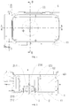
FIG. 1 is a schematic view of a base assembly provided with a filter screen component according to the present application; -
FIG. 2 is a schematic section view along the line A-A inFIG. 1 . -
FIG. 3 is a schematic section view section along the B-B inFIG. 1 . -
FIG. 4 is a schematic view of a structure of a frame of an annular filter screen. -
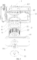
FIG. 5 is a schematic exploded view of the base assembly inFIG. 1 . -
FIG. 6 is a schematic exploded view of the base assembly inFIG. 1 viewed from another direction. -
FIG. 7 is another schematic section view of the base assembly inFIG. 1 . - 1: motor; 11: motor end cover; 2: filter screen part; 21: frame; 211: first annular body; 212: second annular body; 213: connecting rib; 214: end cover; 215: depressed part; 216: opening; 217: shaft sleeve; 22: filter screen; 3: water spray part; 31: nozzle; 4: base; 41: first plate; 411: mounting hole; 42: second plate; 421: exhaust hole; 43: air duct; 44: water pump mount; 45: baffle; 5: first wear sheet; 6: second wear sheet; 7: elastic gasket.
- The specific embodiment of the present application will be described in detail below with reference to the accompanying drawings. It should be understood that the specific embodiment described herein are only used to illustrate and explain the application, and are not used to limit the present application.
- It should be noted that the embodiments of the present application and the characteristics of the embodiments can be combined with each other if there is no conflict.
- In the description of the present application, it should be understood that the orientation or positional relationship indicated by the terms "center", "longitudinal", "transverse", "length", "width", "thickness", "up", "down", "left", "right", "vertical", "horizontal", "top", "bottom", "axial", "radial", "circumferential" is based on the orientation or positional relationship shown in the drawings. It is only for the convenience of describing the present application and simplifying the description, rather than indicating or implying the device or element referred to must have a specific orientation, be constructed and operated in a specific orientation, and therefore cannot be understood as a limitation of the present application. In addition, "inner", "outer" should be understood as the inner and outer relative to the contour of each part itself.
- In addition, the terms "first" and "second" are only used for description purposes, and cannot be understood as indicating or implying relative importance or implicitly indicating the number of indicated technical features. Therefore, the features defined by "first" and "second" may explicitly or implicitly that there is at least one such feature.
- As shown in
FIG. 1 to 3 , the present application provides a filter screen component including amotor 1 and afilter screen part 2 which comprises an annular filter screen body having multiple meshes. An end of the filter screen body is connected to a rotary shaft of themotor 1, and the other end is provided with anopening 216. - The present application provides a filter screen component which can be installed in equipment that needs to filter debris or other impurities, such as a clothes dryer, a washing and drying integrated machine, an air conditioner, or a purifier. As shown in
FIG. 1 to 3 (especially as shown inFIG. 2 ), the filter screen component is installed in anair duct 43 of abase 4 of the clothes dryer, an airflow enters into theair duct 43 from an air inlet on thebase 4. The airflow in theair duct 43 can blow onto an outer surface of the annular filter screen body, to intercept debris in the airflow for drying clothes. Then, the airflow passes through the interior of the annular filter screen body and flows out from theopening 216. Themotor 1 can be activated when it is necessary to remove debris from thefilter screen part 2, then themotor 1 drives thefilter screen part 2 to rotate, and debris and other impurities on thefilter screen part 2 will drop from the filter screen under the action of centrifugal force. Preferably, water is sprayed on thefilter screen part 2 to moisten debris, so that the drop of debris under the action of centrifugal force can be facilitated and rising of dust can be avoided. - The filter screen component provided by the present application cannot only effectively filter impurities such as debris in the airflow, but also have the following advantages in the removing of the debris from the filter: since debris is removed by centrifugal force, there is no need to provide additional cleaning components that are in contact with the filter screen, so as to avoid transferring debris to the additional cleaning components; once the motor is activated, the debris can be removed automatically without manual cleaning; this cleaning method cannot only remove debris from the surface of the filter screen, but also remove debris in the small meshes of the filter screen, and thus a thorough clean is obtained.
- In a specific embodiment of the present application, the
filter screen part 2 further comprises anend cover 214 arranged at the end of the annular filter screen body. The rotary shaft of themotor 1 is connected with theend cover 214. A central part of theend cover 214 is recessed inwardly along an axial direction to form adepressed part 215. Themotor 1 is located at least partially in thedepressed part 215. This arrangement can render the structure compact. - Specifically, the annular
filter screen part 2 comprises aframe 21 and afilter screen 22 arranged on theframe 21. The specific structure of theframe 21 is shown inFIG. 4 , theframe 21 comprises a firstannular body 211 arranged at one end of the frame, a secondannular body 212 arranged at the other end of the frame, and a connectingrib 213 connected between the firstannular body 211 and the secondannular body 212. Thefilter screen 22 having multiple meshes for filtering debris is arranged in a circumferential direction between the firstannular body 211 and the secondannular body 212, to form an annular filter screen body. Theframe 21 also comprises theend cover 214 integrally formed with the firstannular body 211. Theend cover 214 is recessed inward to form adepressed part 215 in the shape of a general frustum. Ashaft sleeve 217 arranged around the rotary shaft of themotor 1 is provided at the bottom of the depressed part 215 (as shown inFIG. 2 ). Theshaft sleeve 217 is fixed to the rotary shaft of themotor 1, to drive thefilter screen part 2 to rotate by themotor 1. - In order to moisten debris on the filter screen, in a preferable embodiment, the filter screen component further comprises a
water spray part 3 for spraying water on the outer circumferential surface of the filter screen body. Thewater spray part 3 may comprisemultiple nozzles 31. As shown inFIG. 3 , in the clothes dryer, thewater spray part 31 can be directly formed on thebase 4 of the clothes dryer. Of course, a separatewater spray part 31 is also possible in this case. - Another aspect of the present application provides a base assembly. As shown in
FIGS.1 to 3 , the base assembly comprises thebase 4 and the filter screen component as described above. Thebase 4 is formed with anair duct 43 for airflow to flow through, themotor 1 is fixed on thebase 4, and the filter screen body of thefilter screen part 2 is located in theair duct 43 to enable the airflow in theair duct 43 to blow onto an outer circumferential surface of the filter screen body, in order to filter debris in the airflow. - Preferably, as shown in
FIG. 7 , thebase 4 comprises abaffle 45 for preventing debris, which is dropped from the filter screen body, from flowing toward an air inlet of thebase 4. Thebaffle 45 extends from a side wall of thebase 4 on an upper side of the outer circumferential surface of the filter screen body, and is formed by being bent toward the outer circumferential surface of the filter screen body. Under the action of thebaffle 45, debris dropped under the action of centrifugal force can flow downward, but cannot flow in the direction of the air inlet. - Preferably, a drainage cavity is formed at a bottom of the
air duct 43; the drainage cavity is in communication with a drainage hole for drainage. Preferably, the drainage cavity is a condensate water cavity provided on thebase 4 for collecting condensate water. After debris are separated under the action of centrifugal force, debris drop into the drainage cavity and can be discharged from the drainage hole with the condensed water, without further manual cleaning. - In addition, the
base 4 can be also provided with awater spray part 3 for spraying water to thefilter screen part 2 and a water pump for supplying water to thewater spray part 3. In an embodiment, as shown inFIG. 3 , thewater spray part 3 is directly formed on the base 4 (that is, a hole operated as anozzle 31 is opened on the structure of thebase 4 to form the water spray part 3), and awater pump mount 44 is provided on thebase 4, and the water pump can be arranged on thewater pump mount 44 to supply water to thewater spray part 3. Of course, it is also possible to provide a separatewater spray part 3 for spraying water, and the water spray part on thebase 2. The water sprayed by thewater spray part 3 carries debris and drops into the drainage cavity, and then debris are discharged from the drainage cavity. - In addition, a water pump can be provided to drain the water from the drainage cavity sooner. The water is drawn out from the drainage hole of the drainage cavity through the water pump.
- Further, the installation of the filter screen component on the
base 4 is shown inFIG. 2 ,FIG. 5 andFIG. 6 . Thebase 4 comprises afirst plate 41 and asecond plate 42 provided with anexhaust hole 421, the first plate and the second plate is arranged opposite to one other. A space between thefirst plate 41 and thesecond plate 42 forms theair duct 43. Themotor 1 of the filter screen component is fixed on thefirst plate 41. The end of thefilter screen part 2 provided with theopening 216 is attached to thesecond plate 42, and theopening 216 is aligned with theexhaust hole 421. - More specifically, as shown in
FIG. 5 , thefirst plate 41 can be detached from thebase 4. Thefirst plate 41 is provided with a mountinghole 411. Themotor 411 is mounted in the mountinghole 411, and themotor 1 is located partially in thedepressed part 215 of theend cover 214 of thefilter screen part 2. Amotor end cover 11 covering the mountinghole 411 is fixed on thefirst plate 41. Themotor end cover 11 is also fixedly connected to themotor 1 to fix the motor on thefirst plate 41. In addition, the arrangement of themotor end cover 11 helps to protect themotor 1 and optimize the appearance. - Due to the end of the filter screen body of the
filter screen part 2 is provided with anend cover 214 while the other end is attached to thesecond plate 42, the airflow in theair duct 43 does not enter into the filter screen body from both ends, the airflow can only enter into it through the meshes on the filter screen body, which will prevent debris from entering into the interior of the filter screen body. - During the rotation, there will be friction between the end of the filter screen body attached to the
second plate 42 and thesecond plate 42. Preferably, in order to avoid friction, the end of the filter screen body provided with theopening 216 is provided with afirst wear sheet 5 surrounding theopening 216, thesecond plate 42 is provided with asecond wear sheet 6 cooperating and rubbing with thefirst wear sheet 5. Thefirst wear sheet 5 and thesecond wear sheet 6 rub against each other during the rotation of thefilter screen part 2. - More specifically, an
elastic gasket 7 is arranged between thesecond plate 42 and thesecond wear sheet 6. When the end of the filter screen body abuts on thesecond plate 42, theelastic gasket 7 can keep the surface of thesecond wear sheet 6 in permanent contact with thefirst wear sheet 5, to realize better seal between thefirst wear sheet 5 and thesecond wear sheet 6, and avoid producing a gap between the first wear sheet and the second wear sheet into which debris can enter. - When the base assembly is used in the clothes dryer (it can also be used in other electrical equipment, here is the clothes dryer as an example), the airflow generated by the clothes dryer during the clothes drying process flows through the
filter screen part 2. Thefilter screen part 2 can filter impurities (such as debris) in the airflow. After the clothes drying is finished, themotor 1 can be activated when it is necessary to remove debris from thefilter screen part 2. Themotor 1 drives thefilter screen part 2 to rotate, and water can be sprayed to the filter screen of thefilter screen part 2 by thewater spray part 3 at the same time. Debris drops into the drainage cavity under the action of centrifugal force, and is directly discharged with the water in the drainage cavity, without manual cleaning. - According to yet another aspect of the application provides a clothes dryer including the base assembly as described above.
- According to still another aspect of the application provides a washing and drying integrated machine including the base assembly as described above. Herein, the washing and drying integrated machine is electrical equipment with washing and drying functions.
- The preferred embodiments of the present application are described in detail above with reference to the accompanying drawings, but the present application is not limited thereto. Within the scope of the technical concept of the present application, multiple simple modifications can be made to the technical solution of the present application, including individual specific technical features combined in any suitable manner. In order to avoid unnecessary repetition, various possible combinations are not described separately in the present application. However, these simple modifications and combinations should also be regarded as the contents disclosed in the present application, and all belong to the protection scope of the present application.
Claims (13)
- A filter screen component, comprising a motor (1) and a filter screen part (2), the filter screen part (2) comprising an annular filter screen body having a plurality of meshes, an end of the filter screen body being connected to a rotary shaft of the motor (1), and the other end being provided with an opening (216).
- The filter screen component according to claim 1, wherein the filter screen part (2) further comprises an end cover (214) arranged at the end of the filter screen body, the motor (1) being connected with the end cover (214), a central part of the end cover (214) being recessed inwardly along an axial direction to form a depressed part (215), and the motor (1) being located at least partially in the depressed part (215).
- The filter screen component according to claim 1 or 2, further comprising a water spray part (3) for spraying water to the filter screen body.
- The filter screen component according to claim 3, wherein the water spray part (3) is located in an interior of the filter screen body to spray water from the interior to an inner circumferential surface of the filter screen body, or the water spray part is located outside the filter screen body to spray water to an outer circumferential surface of the filter screen body.
- A base assembly, comprising a base (4) and the filter screen component according to any one of claims 1 to 4, wherein the base (4) is formed with an air duct (43) for airflow to flow through, the motor (1) being fixed on the base (4), and the filter screen body of the filter screen part (2) being located in the air duct (43) to enable the airflow in the air duct (43) to blow onto an outer circumferential surface of the filter screen body.
- The base assembly according to claim 5, wherein a drainage cavity is formed at a bottom of the air duct (43), the drainage cavity being in communication with a drainage hole for drainage.
- The base assembly according to claim 6, further comprising a water pump for drawing water out of the drainage cavity through the drainage hole.
- The base assembly according to one of claims 5 to 7, wherein the base (4) comprises a first plate (41) and a second plate (42) provided with an exhaust hole (421), the first plate and the second plate arranged opposite to one other, a space between the first plate (41) and the second plate (42) forming the air duct (43), the motor (1) of the filter screen component being fixed on the first plate (41), the end of the filter screen part (2) provided with the opening (216) being attached to the second plate (42), and the opening (216) being aligned with the exhaust hole (421).
- The base assembly according to claim 8, wherein the end of the filter screen part (2) provided with the opening (216) is provided with a first wear sheet (5) surrounding the opening (216), the second plate (42) being provided with a second wear sheet (6) cooperating and rubbing with the first wear sheet (5).
- The base assembly according to claim 9, wherein an elastic gasket (7) is arranged between the second plate (42) and the second wear sheet (6).
- The base assembly according to one of claims 5 to 7, wherein the base (4) comprises a baffle for preventing debris dropped from the filter screen body from flowing toward an air inlet of the base.
- A clothes dryer, comprising the base assembly according to any one of claims 5 to 11.
- A washing and drying integrated machine, comprising the base assembly according to any one of claims 5 to 11.
Applications Claiming Priority (2)
| Application Number | Priority Date | Filing Date | Title |
|---|---|---|---|
| CN201811198967.XA CN111041801B (en) | 2018-10-15 | 2018-10-15 | Filter screen assembly, base assembly, clothes dryer and washing and drying integrated machine |
| PCT/CN2018/122315 WO2020077801A1 (en) | 2018-10-15 | 2018-12-20 | Filter screen component, base assembly, clothes dryer, and washing and drying integrated machine |
Publications (3)
| Publication Number | Publication Date |
|---|---|
| EP3848498A1 true EP3848498A1 (en) | 2021-07-14 |
| EP3848498A4 EP3848498A4 (en) | 2021-11-17 |
| EP3848498B1 EP3848498B1 (en) | 2025-01-22 |
Family
ID=70230444
Family Applications (1)
| Application Number | Title | Priority Date | Filing Date |
|---|---|---|---|
| EP18937239.4A Active EP3848498B1 (en) | 2018-10-15 | 2018-12-20 | Filter screen component, base assembly, clothes dryer, and washing and drying integrated machine |
Country Status (5)
| Country | Link |
|---|---|
| US (1) | US12290777B2 (en) |
| EP (1) | EP3848498B1 (en) |
| JP (1) | JP7488004B2 (en) |
| CN (1) | CN111041801B (en) |
| WO (1) | WO2020077801A1 (en) |
Families Citing this family (9)
| Publication number | Priority date | Publication date | Assignee | Title |
|---|---|---|---|---|
| CN113465347B (en) * | 2021-07-13 | 2022-06-21 | 江西师范大学 | Air shower type rapid drying device for food vacuum packaging |
| CN115613308B (en) * | 2021-07-15 | 2026-01-23 | 无锡小天鹅电器有限公司 | Filter assembly and clothes treatment equipment with same |
| CN116196709B (en) * | 2021-12-01 | 2026-02-10 | 广东美的白色家电技术创新中心有限公司 | A filtration device and a clothing treatment system |
| CN114293357B (en) * | 2021-12-01 | 2024-02-20 | 广东美的白色家电技术创新中心有限公司 | Clothes processing equipment and control method, device and storage medium thereof |
| CN116289126A (en) * | 2021-12-21 | 2023-06-23 | 无锡小天鹅电器有限公司 | Base assembly for drying equipment and drying equipment having same |
| CN116334892B (en) * | 2021-12-24 | 2025-07-04 | 无锡小天鹅电器有限公司 | A clothes dryer and base assembly thereof |
| CN116427153A (en) * | 2022-01-04 | 2023-07-14 | 无锡小天鹅电器有限公司 | Clothes processing device control method and clothes processing device |
| CN115302305B (en) * | 2022-07-27 | 2024-10-25 | 西安理工大学 | A cutting fluid filter with centrifugal function for machine tool applications |
| CN115945002B (en) * | 2022-12-21 | 2025-10-28 | 珠海格力电器股份有限公司 | Self-cleaning filter device and clothes dryer having the same |
Family Cites Families (65)
| Publication number | Priority date | Publication date | Assignee | Title |
|---|---|---|---|---|
| US1975335A (en) * | 1931-07-06 | 1934-10-02 | Continental Gin Co | Separator |
| US3085348A (en) * | 1957-01-23 | 1963-04-16 | Oxy Catalyst Inc | Lint remover for fabric dryer |
| US3132006A (en) * | 1958-01-23 | 1964-05-05 | Gen Motors Corp | Lint burner for a domestic dryer |
| FR1207441A (en) * | 1958-04-15 | 1960-02-16 | Rotary filter | |
| US3034223A (en) * | 1959-04-01 | 1962-05-15 | Gen Electric | Clothes drying machine |
| US3306596A (en) * | 1965-01-28 | 1967-02-28 | American Gas Ass | Heated-gas system with apparatus for removing gas-borne foreign bodies |
| US3382014A (en) * | 1966-02-18 | 1968-05-07 | Garrett Corp | Self-acting foil bearings |
| US3443696A (en) * | 1967-05-01 | 1969-05-13 | Little Inc A | Solid-fluid separating device |
| US3448858A (en) * | 1968-07-25 | 1969-06-10 | Ingersoll Rand Canada | Centrifugal filtering apparatus |
| US3677612A (en) * | 1969-04-03 | 1972-07-18 | Garrett Corp | Coated fluid bearing foils and fabricating method |
| US3635534A (en) * | 1969-08-06 | 1972-01-18 | Garrett Corp | Self-pressurizing bearings with resilient elements |
| GB1386526A (en) * | 1972-05-25 | 1975-03-05 | Challenge Cook Bros Inc | Lint disposal apparatus |
| US3977847A (en) * | 1975-08-08 | 1976-08-31 | Brunswick Corporation | Filtration method and apparatus |
| US4108778A (en) * | 1976-02-25 | 1978-08-22 | Lambert Steven J | Self-cleaning filter and vortexer |
| DE2802369A1 (en) * | 1978-01-20 | 1979-07-26 | Ltg Lufttechnische Gmbh | FILTER DEVICE FOR FILTERING AIR POLLUTED BY DUST AND FIBER WASTE |
| US4208076A (en) * | 1978-12-29 | 1980-06-17 | Mechanical Technology Incorporated | Compliant hydrodynamic bearing with improved support element |
| US4314409A (en) * | 1980-02-06 | 1982-02-09 | Whirlpool Corporation | Automatic lint screen cleaner and storage system for dryer |
| US4296976A (en) * | 1980-04-03 | 1981-10-27 | Mechanical Technology Incorporated | Cross-plies support element for compliant bearings |
| US4462170A (en) * | 1982-05-21 | 1984-07-31 | Whirlpool Corporation | Sump for lint screen cleaner and storage system for a dryer |
| US4621930A (en) * | 1984-10-01 | 1986-11-11 | The Garrett Corporation | Foil thrust bearing cooling |
| US4624583A (en) * | 1984-10-01 | 1986-11-25 | The Garrett Corporation | Foil thrust bearing |
| US4682900A (en) * | 1985-12-19 | 1987-07-28 | The Garrett Corporation | Thrust bearing underspring |
| IT1220748B (en) * | 1988-05-04 | 1990-06-21 | Zanussi A Spa Industrie | CONVERTIBLE WASHING MACHINE IN COMBINED MACHINE FOR WASHING AND DRYING THE LINEN |
| US4899462A (en) * | 1988-10-14 | 1990-02-13 | Speed Queen Company | Lint burning clothes dryer |
| US4885009A (en) * | 1988-11-09 | 1989-12-05 | Battelle Memorial Institute | Coaxial screen filter |
| US4969934A (en) * | 1989-08-04 | 1990-11-13 | The United States Of America As Represented By The United States Department Of Energy | Method for improved gas-solids separation |
| US5143528A (en) * | 1990-02-14 | 1992-09-01 | Challenge Industries | Lint collector |
| US5157848A (en) * | 1990-02-14 | 1992-10-27 | Challenge Industries | Lint collector |
| US5376268A (en) * | 1993-04-07 | 1994-12-27 | Nessy Kogyo Kabushiki Kaisha | Rotary filtering apparatus |
| JP3557002B2 (en) * | 1995-07-14 | 2004-08-25 | 三洋電機株式会社 | Electrical equipment |
| US5938341A (en) * | 1998-02-09 | 1999-08-17 | Alliedsignal Inc. | Foil thrust bearing including a follower spring having rotated, elongated spring tabs |
| JPH11270887A (en) * | 1998-03-24 | 1999-10-05 | Sanyo Electric Co Ltd | Ventilation dryer |
| US6354741B1 (en) * | 1999-01-22 | 2002-03-12 | Alliedsignal Inc. | Foil thrust bearing |
| US6311796B1 (en) * | 1999-11-05 | 2001-11-06 | General Motors Corporation | Equipment compartment with slidable hood |
| US20010010486A1 (en) * | 1999-12-15 | 2001-08-02 | Trombetta, Llc | Method of forming a seamless solenoid plunger wear band |
| JP2001248869A (en) * | 2000-03-07 | 2001-09-14 | Shinko Kogyo Co Ltd | Clean room filter unit |
| US6540914B1 (en) * | 2000-04-24 | 2003-04-01 | Vortex International, Llc | Cleanable filter with spinning screen |
| US6569218B2 (en) * | 2001-03-08 | 2003-05-27 | David Edmond Dudley | Self spin-cleaning canister vacuum |
| DE60218045T2 (en) * | 2001-07-06 | 2007-06-06 | R & D Dynamics Corp., Bloomfield | HYDRODYNAMIC FILM SEALING SEAL |
| US6948853B2 (en) * | 2002-10-03 | 2005-09-27 | R & D Dynamics Corporation | High load capacity stacked foil thrust bearing assembly |
| US6890375B2 (en) * | 2003-02-20 | 2005-05-10 | Keith L. Huber | Cyclonic air filter with exit baffle |
| US7055262B2 (en) * | 2003-09-29 | 2006-06-06 | Self Propelled Research And Development Specialists, Llc | Heat pump clothes dryer |
| US7497627B2 (en) * | 2004-06-07 | 2009-03-03 | Honeywell International Inc. | Thrust bearing |
| CN2837343Y (en) * | 2005-07-21 | 2006-11-15 | 江苏海狮机械集团有限公司 | Centrifugal type filter used in dry cleaner |
| JP4706571B2 (en) | 2006-06-29 | 2011-06-22 | パナソニック株式会社 | Washing and drying machine |
| US20080104856A1 (en) * | 2006-11-08 | 2008-05-08 | Armstrong Malcolm C C | Quick Time Drying Apparatus and Method for Clothes Dryers |
| US20080235978A1 (en) * | 2007-03-26 | 2008-10-02 | Michael Epstein | Self-cleaning lint collector |
| JP2009142351A (en) * | 2007-12-12 | 2009-07-02 | Hitachi Appliances Inc | Laundry dryer and dryer |
| KR101070536B1 (en) * | 2008-12-17 | 2011-10-05 | 엘지전자 주식회사 | Dryer and apparatus for removing lint thereof and control method thereof |
| JP2011012743A (en) * | 2009-07-01 | 2011-01-20 | Techno Ryowa Ltd | Sealing device, and rotor including the same |
| GB201014953D0 (en) * | 2010-09-08 | 2010-10-20 | Birkbeck Hilary R | Slide chair action |
| WO2012134159A2 (en) * | 2011-03-28 | 2012-10-04 | 엘지전자 주식회사 | Laundry treating apparatus, and method for washing a lint filter of a laundry treating apparatus |
| EP2695986B1 (en) * | 2011-04-05 | 2016-07-20 | LG Electronics Inc. | Laundry machine and method for cleaning lint filter of laundry machine |
| US8651743B2 (en) * | 2011-04-19 | 2014-02-18 | Us Synthetic Corporation | Tilting superhard bearing elements in bearing assemblies, apparatuses, and motor assemblies using the same |
| US8646981B2 (en) * | 2011-04-19 | 2014-02-11 | Us Synthetic Corporation | Bearing elements, bearing assemblies, and related methods |
| JP2013135789A (en) * | 2011-12-28 | 2013-07-11 | Panasonic Corp | Clothing drying machine |
| DE102013108565B4 (en) * | 2013-08-08 | 2024-03-14 | Miele & Cie. Kg | Vacuum cleaner with a filter element |
| US9474376B2 (en) * | 2013-08-27 | 2016-10-25 | Everitt Drew | Portable back pack swivel seat |
| JP6373020B2 (en) * | 2014-03-06 | 2018-08-15 | シャープ株式会社 | Dryer |
| KR102151191B1 (en) * | 2014-04-17 | 2020-09-02 | 엘지전자 주식회사 | Dryer for clothes |
| US10280552B2 (en) * | 2016-08-01 | 2019-05-07 | Haier Us Appliance Solutions, Inc. | Filter assembly for a dryer appliance |
| CN206843794U (en) * | 2017-05-25 | 2018-01-05 | 上海有洗洗涤设备有限公司 | A kind of petroleum dry-washer filter |
| CN107568324A (en) * | 2017-09-14 | 2018-01-12 | 田阳县群姐砂糖橘专业合作社 | A kind of fresh-keeping treating method of granulated sugar tangerine |
| WO2022258058A1 (en) * | 2021-06-11 | 2022-12-15 | 广东美的白色家电技术创新中心有限公司 | Food processor, food processor host, and food processor control method |
| US12173751B2 (en) * | 2023-01-31 | 2024-12-24 | Hamilton Sundstrand Corporation | Multipad hybrid conical foil bearing |
-
2018
- 2018-10-15 CN CN201811198967.XA patent/CN111041801B/en active Active
- 2018-12-20 JP JP2021543551A patent/JP7488004B2/en active Active
- 2018-12-20 WO PCT/CN2018/122315 patent/WO2020077801A1/en not_active Ceased
- 2018-12-20 EP EP18937239.4A patent/EP3848498B1/en active Active
- 2018-12-20 US US17/284,469 patent/US12290777B2/en active Active
Also Published As
| Publication number | Publication date |
|---|---|
| US12290777B2 (en) | 2025-05-06 |
| JP2022508578A (en) | 2022-01-19 |
| JP7488004B2 (en) | 2024-05-21 |
| CN111041801A (en) | 2020-04-21 |
| CN111041801B (en) | 2021-08-10 |
| EP3848498B1 (en) | 2025-01-22 |
| US20210394106A1 (en) | 2021-12-23 |
| EP3848498A4 (en) | 2021-11-17 |
| WO2020077801A1 (en) | 2020-04-23 |
Similar Documents
| Publication | Publication Date | Title |
|---|---|---|
| US12290777B2 (en) | Filter screen component, base assembly, clothes dryer, and washing and drying integrated machine | |
| KR101349844B1 (en) | Laundry Machine Having a Drying Function | |
| EP4144909B1 (en) | Integrated washer-dryer | |
| CN113308863B (en) | Condenser for clothes treatment device and clothes treatment device | |
| WO2019085738A1 (en) | Filtering device capable of performing automatic cleaning, and clothes processing device | |
| CN106948147B (en) | Heat pump assembly for washing-drying integral machine and the washing-drying integral machine with it | |
| JP7015100B2 (en) | Lint filter and clothes dryer | |
| CN112831995B (en) | Clothes treating apparatus | |
| CN108729170A (en) | The drying system and washing machine of washing machine | |
| CN211713438U (en) | Clothes treating apparatus | |
| CN113827145A (en) | A cleaning assembly for easy removal of roller brushes | |
| JP2017125658A (en) | Range food | |
| EP4067559B1 (en) | Clothes drying device | |
| CN112301626B (en) | Clothes processing equipment | |
| US4288885A (en) | Hot water vacuum extraction machine with reverse fan cooled vacuum motor | |
| CN115506134A (en) | Clothes treatment device | |
| CN223837783U (en) | Air duct system of clothes treatment equipment and clothes treatment equipment | |
| CN219862020U (en) | Filtering component and clothes treatment equipment | |
| CN219862017U (en) | Clothes treating apparatus | |
| CN223738356U (en) | Air duct system of clothes treatment equipment and clothes treatment equipment | |
| CN219862021U (en) | Filtering component and clothes treatment equipment | |
| CN115506135A (en) | Clothes treatment device | |
| JP2021519648A (en) | Clothes processing equipment | |
| CN219862015U (en) | Clothes treating apparatus | |
| CN220284429U (en) | Spraying structure and washing machine |
Legal Events
| Date | Code | Title | Description |
|---|---|---|---|
| STAA | Information on the status of an ep patent application or granted ep patent |
Free format text: STATUS: THE INTERNATIONAL PUBLICATION HAS BEEN MADE |
|
| PUAI | Public reference made under article 153(3) epc to a published international application that has entered the european phase |
Free format text: ORIGINAL CODE: 0009012 |
|
| STAA | Information on the status of an ep patent application or granted ep patent |
Free format text: STATUS: REQUEST FOR EXAMINATION WAS MADE |
|
| 17P | Request for examination filed |
Effective date: 20210408 |
|
| AK | Designated contracting states |
Kind code of ref document: A1 Designated state(s): AL AT BE BG CH CY CZ DE DK EE ES FI FR GB GR HR HU IE IS IT LI LT LU LV MC MK MT NL NO PL PT RO RS SE SI SK SM TR |
|
| A4 | Supplementary search report drawn up and despatched |
Effective date: 20211014 |
|
| RIC1 | Information provided on ipc code assigned before grant |
Ipc: D06F 25/00 20060101ALN20211008BHEP Ipc: D06F 58/22 20060101AFI20211008BHEP |
|
| DAV | Request for validation of the european patent (deleted) | ||
| DAX | Request for extension of the european patent (deleted) | ||
| STAA | Information on the status of an ep patent application or granted ep patent |
Free format text: STATUS: EXAMINATION IS IN PROGRESS |
|
| 17Q | First examination report despatched |
Effective date: 20230303 |
|
| GRAP | Despatch of communication of intention to grant a patent |
Free format text: ORIGINAL CODE: EPIDOSNIGR1 |
|
| STAA | Information on the status of an ep patent application or granted ep patent |
Free format text: STATUS: GRANT OF PATENT IS INTENDED |
|
| RIC1 | Information provided on ipc code assigned before grant |
Ipc: D06F 25/00 20060101ALN20240717BHEP Ipc: D06F 58/22 20060101AFI20240717BHEP |
|
| INTG | Intention to grant announced |
Effective date: 20240808 |
|
| GRAS | Grant fee paid |
Free format text: ORIGINAL CODE: EPIDOSNIGR3 |
|
| GRAA | (expected) grant |
Free format text: ORIGINAL CODE: 0009210 |
|
| STAA | Information on the status of an ep patent application or granted ep patent |
Free format text: STATUS: THE PATENT HAS BEEN GRANTED |
|
| AK | Designated contracting states |
Kind code of ref document: B1 Designated state(s): AL AT BE BG CH CY CZ DE DK EE ES FI FR GB GR HR HU IE IS IT LI LT LU LV MC MK MT NL NO PL PT RO RS SE SI SK SM TR |
|
| REG | Reference to a national code |
Ref country code: GB Ref legal event code: FG4D |
|
| REG | Reference to a national code |
Ref country code: CH Ref legal event code: EP |
|
| REG | Reference to a national code |
Ref country code: IE Ref legal event code: FG4D |
|
| REG | Reference to a national code |
Ref country code: DE Ref legal event code: R096 Ref document number: 602018078784 Country of ref document: DE |
|
| REG | Reference to a national code |
Ref country code: NL Ref legal event code: MP Effective date: 20250122 |
|
| PG25 | Lapsed in a contracting state [announced via postgrant information from national office to epo] |
Ref country code: NL Free format text: LAPSE BECAUSE OF FAILURE TO SUBMIT A TRANSLATION OF THE DESCRIPTION OR TO PAY THE FEE WITHIN THE PRESCRIBED TIME-LIMIT Effective date: 20250122 |
|
| PG25 | Lapsed in a contracting state [announced via postgrant information from national office to epo] |
Ref country code: RS Free format text: LAPSE BECAUSE OF FAILURE TO SUBMIT A TRANSLATION OF THE DESCRIPTION OR TO PAY THE FEE WITHIN THE PRESCRIBED TIME-LIMIT Effective date: 20250422 |
|
| PG25 | Lapsed in a contracting state [announced via postgrant information from national office to epo] |
Ref country code: FI Free format text: LAPSE BECAUSE OF FAILURE TO SUBMIT A TRANSLATION OF THE DESCRIPTION OR TO PAY THE FEE WITHIN THE PRESCRIBED TIME-LIMIT Effective date: 20250122 |
|
| PG25 | Lapsed in a contracting state [announced via postgrant information from national office to epo] |
Ref country code: PL Free format text: LAPSE BECAUSE OF FAILURE TO SUBMIT A TRANSLATION OF THE DESCRIPTION OR TO PAY THE FEE WITHIN THE PRESCRIBED TIME-LIMIT Effective date: 20250122 |
|
| PG25 | Lapsed in a contracting state [announced via postgrant information from national office to epo] |
Ref country code: ES Free format text: LAPSE BECAUSE OF FAILURE TO SUBMIT A TRANSLATION OF THE DESCRIPTION OR TO PAY THE FEE WITHIN THE PRESCRIBED TIME-LIMIT Effective date: 20250122 |
|
| REG | Reference to a national code |
Ref country code: LT Ref legal event code: MG9D |
|
| PG25 | Lapsed in a contracting state [announced via postgrant information from national office to epo] |
Ref country code: IS Free format text: LAPSE BECAUSE OF FAILURE TO SUBMIT A TRANSLATION OF THE DESCRIPTION OR TO PAY THE FEE WITHIN THE PRESCRIBED TIME-LIMIT Effective date: 20250522 Ref country code: NO Free format text: LAPSE BECAUSE OF FAILURE TO SUBMIT A TRANSLATION OF THE DESCRIPTION OR TO PAY THE FEE WITHIN THE PRESCRIBED TIME-LIMIT Effective date: 20250422 |
|
| REG | Reference to a national code |
Ref country code: AT Ref legal event code: MK05 Ref document number: 1761546 Country of ref document: AT Kind code of ref document: T Effective date: 20250122 |
|
| PG25 | Lapsed in a contracting state [announced via postgrant information from national office to epo] |
Ref country code: HR Free format text: LAPSE BECAUSE OF FAILURE TO SUBMIT A TRANSLATION OF THE DESCRIPTION OR TO PAY THE FEE WITHIN THE PRESCRIBED TIME-LIMIT Effective date: 20250122 |
|
| PG25 | Lapsed in a contracting state [announced via postgrant information from national office to epo] |
Ref country code: LV Free format text: LAPSE BECAUSE OF FAILURE TO SUBMIT A TRANSLATION OF THE DESCRIPTION OR TO PAY THE FEE WITHIN THE PRESCRIBED TIME-LIMIT Effective date: 20250122 Ref country code: PT Free format text: LAPSE BECAUSE OF FAILURE TO SUBMIT A TRANSLATION OF THE DESCRIPTION OR TO PAY THE FEE WITHIN THE PRESCRIBED TIME-LIMIT Effective date: 20250522 |
|
| PG25 | Lapsed in a contracting state [announced via postgrant information from national office to epo] |
Ref country code: GR Free format text: LAPSE BECAUSE OF FAILURE TO SUBMIT A TRANSLATION OF THE DESCRIPTION OR TO PAY THE FEE WITHIN THE PRESCRIBED TIME-LIMIT Effective date: 20250423 Ref country code: BG Free format text: LAPSE BECAUSE OF FAILURE TO SUBMIT A TRANSLATION OF THE DESCRIPTION OR TO PAY THE FEE WITHIN THE PRESCRIBED TIME-LIMIT Effective date: 20250122 |
|
| PG25 | Lapsed in a contracting state [announced via postgrant information from national office to epo] |
Ref country code: AT Free format text: LAPSE BECAUSE OF FAILURE TO SUBMIT A TRANSLATION OF THE DESCRIPTION OR TO PAY THE FEE WITHIN THE PRESCRIBED TIME-LIMIT Effective date: 20250122 |
|
| PG25 | Lapsed in a contracting state [announced via postgrant information from national office to epo] |
Ref country code: SE Free format text: LAPSE BECAUSE OF FAILURE TO SUBMIT A TRANSLATION OF THE DESCRIPTION OR TO PAY THE FEE WITHIN THE PRESCRIBED TIME-LIMIT Effective date: 20250122 |
|
| PG25 | Lapsed in a contracting state [announced via postgrant information from national office to epo] |
Ref country code: SM Free format text: LAPSE BECAUSE OF FAILURE TO SUBMIT A TRANSLATION OF THE DESCRIPTION OR TO PAY THE FEE WITHIN THE PRESCRIBED TIME-LIMIT Effective date: 20250122 |
|
| PG25 | Lapsed in a contracting state [announced via postgrant information from national office to epo] |
Ref country code: DK Free format text: LAPSE BECAUSE OF FAILURE TO SUBMIT A TRANSLATION OF THE DESCRIPTION OR TO PAY THE FEE WITHIN THE PRESCRIBED TIME-LIMIT Effective date: 20250122 |
|
| PG25 | Lapsed in a contracting state [announced via postgrant information from national office to epo] |
Ref country code: IT Free format text: LAPSE BECAUSE OF FAILURE TO SUBMIT A TRANSLATION OF THE DESCRIPTION OR TO PAY THE FEE WITHIN THE PRESCRIBED TIME-LIMIT Effective date: 20250122 |
|
| PG25 | Lapsed in a contracting state [announced via postgrant information from national office to epo] |
Ref country code: CZ Free format text: LAPSE BECAUSE OF FAILURE TO SUBMIT A TRANSLATION OF THE DESCRIPTION OR TO PAY THE FEE WITHIN THE PRESCRIBED TIME-LIMIT Effective date: 20250122 Ref country code: EE Free format text: LAPSE BECAUSE OF FAILURE TO SUBMIT A TRANSLATION OF THE DESCRIPTION OR TO PAY THE FEE WITHIN THE PRESCRIBED TIME-LIMIT Effective date: 20250122 |
|
| REG | Reference to a national code |
Ref country code: DE Ref legal event code: R097 Ref document number: 602018078784 Country of ref document: DE |
|
| PG25 | Lapsed in a contracting state [announced via postgrant information from national office to epo] |
Ref country code: RO Free format text: LAPSE BECAUSE OF FAILURE TO SUBMIT A TRANSLATION OF THE DESCRIPTION OR TO PAY THE FEE WITHIN THE PRESCRIBED TIME-LIMIT Effective date: 20250122 |
|
| PG25 | Lapsed in a contracting state [announced via postgrant information from national office to epo] |
Ref country code: SK Free format text: LAPSE BECAUSE OF FAILURE TO SUBMIT A TRANSLATION OF THE DESCRIPTION OR TO PAY THE FEE WITHIN THE PRESCRIBED TIME-LIMIT Effective date: 20250122 |
|
| PLBE | No opposition filed within time limit |
Free format text: ORIGINAL CODE: 0009261 |
|
| STAA | Information on the status of an ep patent application or granted ep patent |
Free format text: STATUS: NO OPPOSITION FILED WITHIN TIME LIMIT |
|
| 26N | No opposition filed |
Effective date: 20251023 |
|
| PGFP | Annual fee paid to national office [announced via postgrant information from national office to epo] |
Ref country code: DE Payment date: 20251212 Year of fee payment: 8 |
|
| PGFP | Annual fee paid to national office [announced via postgrant information from national office to epo] |
Ref country code: GB Payment date: 20251211 Year of fee payment: 8 |
|
| PGFP | Annual fee paid to national office [announced via postgrant information from national office to epo] |
Ref country code: FR Payment date: 20251212 Year of fee payment: 8 |