EP3848239B1 - Kindersicherheitssitz - Google Patents
Kindersicherheitssitz Download PDFInfo
- Publication number
- EP3848239B1 EP3848239B1 EP18932840.4A EP18932840A EP3848239B1 EP 3848239 B1 EP3848239 B1 EP 3848239B1 EP 18932840 A EP18932840 A EP 18932840A EP 3848239 B1 EP3848239 B1 EP 3848239B1
- Authority
- EP
- European Patent Office
- Prior art keywords
- lock pin
- slot
- head support
- plate cover
- child safety
- Prior art date
- Legal status (The legal status is an assumption and is not a legal conclusion. Google has not performed a legal analysis and makes no representation as to the accuracy of the status listed.)
- Active
Links
Images


Classifications
-
- B—PERFORMING OPERATIONS; TRANSPORTING
- B60—VEHICLES IN GENERAL
- B60N—SEATS SPECIALLY ADAPTED FOR VEHICLES; VEHICLE PASSENGER ACCOMMODATION NOT OTHERWISE PROVIDED FOR
- B60N2/00—Seats specially adapted for vehicles; Arrangement or mounting of seats in vehicles
- B60N2/24—Seats specially adapted for vehicles; Arrangement or mounting of seats in vehicles for particular purposes or particular vehicles
- B60N2/26—Seats specially adapted for vehicles; Arrangement or mounting of seats in vehicles for particular purposes or particular vehicles for children
- B60N2/28—Seats readily mountable on, and dismountable from, existing seats or other parts of the vehicle
- B60N2/2803—Adaptations for seat belts
- B60N2/2812—Adaptations for seat belts for securing the child to the child seat
-
- B—PERFORMING OPERATIONS; TRANSPORTING
- B60—VEHICLES IN GENERAL
- B60N—SEATS SPECIALLY ADAPTED FOR VEHICLES; VEHICLE PASSENGER ACCOMMODATION NOT OTHERWISE PROVIDED FOR
- B60N2/00—Seats specially adapted for vehicles; Arrangement or mounting of seats in vehicles
- B60N2/24—Seats specially adapted for vehicles; Arrangement or mounting of seats in vehicles for particular purposes or particular vehicles
- B60N2/26—Seats specially adapted for vehicles; Arrangement or mounting of seats in vehicles for particular purposes or particular vehicles for children
- B60N2/28—Seats readily mountable on, and dismountable from, existing seats or other parts of the vehicle
- B60N2/2803—Adaptations for seat belts
- B60N2/2816—Adaptations for seat belts with additional belt accessories, e.g. belt tension detectors
-
- B—PERFORMING OPERATIONS; TRANSPORTING
- B60—VEHICLES IN GENERAL
- B60N—SEATS SPECIALLY ADAPTED FOR VEHICLES; VEHICLE PASSENGER ACCOMMODATION NOT OTHERWISE PROVIDED FOR
- B60N2/00—Seats specially adapted for vehicles; Arrangement or mounting of seats in vehicles
- B60N2/24—Seats specially adapted for vehicles; Arrangement or mounting of seats in vehicles for particular purposes or particular vehicles
- B60N2/26—Seats specially adapted for vehicles; Arrangement or mounting of seats in vehicles for particular purposes or particular vehicles for children
- B60N2/28—Seats readily mountable on, and dismountable from, existing seats or other parts of the vehicle
- B60N2/2803—Adaptations for seat belts
- B60N2/2818—Adaptations for seat belts characterised by guiding means for children belts
-
- B—PERFORMING OPERATIONS; TRANSPORTING
- B60—VEHICLES IN GENERAL
- B60N—SEATS SPECIALLY ADAPTED FOR VEHICLES; VEHICLE PASSENGER ACCOMMODATION NOT OTHERWISE PROVIDED FOR
- B60N2/00—Seats specially adapted for vehicles; Arrangement or mounting of seats in vehicles
- B60N2/24—Seats specially adapted for vehicles; Arrangement or mounting of seats in vehicles for particular purposes or particular vehicles
- B60N2/26—Seats specially adapted for vehicles; Arrangement or mounting of seats in vehicles for particular purposes or particular vehicles for children
- B60N2/28—Seats readily mountable on, and dismountable from, existing seats or other parts of the vehicle
- B60N2/2851—Seats readily mountable on, and dismountable from, existing seats or other parts of the vehicle provided with head-rests
-
- B—PERFORMING OPERATIONS; TRANSPORTING
- B60—VEHICLES IN GENERAL
- B60N—SEATS SPECIALLY ADAPTED FOR VEHICLES; VEHICLE PASSENGER ACCOMMODATION NOT OTHERWISE PROVIDED FOR
- B60N2/00—Seats specially adapted for vehicles; Arrangement or mounting of seats in vehicles
- B60N2/24—Seats specially adapted for vehicles; Arrangement or mounting of seats in vehicles for particular purposes or particular vehicles
- B60N2/26—Seats specially adapted for vehicles; Arrangement or mounting of seats in vehicles for particular purposes or particular vehicles for children
- B60N2/28—Seats readily mountable on, and dismountable from, existing seats or other parts of the vehicle
- B60N2/2866—Seats readily mountable on, and dismountable from, existing seats or other parts of the vehicle booster cushions, e.g. to lift a child to allow proper use of the conventional safety belts
-
- B—PERFORMING OPERATIONS; TRANSPORTING
- B60—VEHICLES IN GENERAL
- B60N—SEATS SPECIALLY ADAPTED FOR VEHICLES; VEHICLE PASSENGER ACCOMMODATION NOT OTHERWISE PROVIDED FOR
- B60N2/00—Seats specially adapted for vehicles; Arrangement or mounting of seats in vehicles
- B60N2/24—Seats specially adapted for vehicles; Arrangement or mounting of seats in vehicles for particular purposes or particular vehicles
- B60N2/26—Seats specially adapted for vehicles; Arrangement or mounting of seats in vehicles for particular purposes or particular vehicles for children
- B60N2/28—Seats readily mountable on, and dismountable from, existing seats or other parts of the vehicle
- B60N2/2875—Seats readily mountable on, and dismountable from, existing seats or other parts of the vehicle inclinable, as a whole or partially
- B60N2/2878—Seats readily mountable on, and dismountable from, existing seats or other parts of the vehicle inclinable, as a whole or partially the back-rest being inclinable
-
- B—PERFORMING OPERATIONS; TRANSPORTING
- B60—VEHICLES IN GENERAL
- B60N—SEATS SPECIALLY ADAPTED FOR VEHICLES; VEHICLE PASSENGER ACCOMMODATION NOT OTHERWISE PROVIDED FOR
- B60N2/00—Seats specially adapted for vehicles; Arrangement or mounting of seats in vehicles
- B60N2/24—Seats specially adapted for vehicles; Arrangement or mounting of seats in vehicles for particular purposes or particular vehicles
- B60N2/26—Seats specially adapted for vehicles; Arrangement or mounting of seats in vehicles for particular purposes or particular vehicles for children
- B60N2/28—Seats readily mountable on, and dismountable from, existing seats or other parts of the vehicle
- B60N2/2887—Fixation to a transversal anchorage bar, e.g. isofix
Definitions
- the present invention relates to the field of children products, in particular to a child safety seat.
- US20170120781A1 discloses a child restraint with belt management system.
- the child restraint includes a juvenile seat and a child-restraint harness coupled to the juvenile seat.
- the child-restraint harness includes a crotch belt having a buckle and two shoulder belts that can be linked to the buckle to restrain a child sitting on the juvenile seat.
- DE102015109108A1 discloses a child seat device.
- the invention is based on a child seat device with a seat base unit which provides a seating and/or lying surface for a child, with a head part which can be adjusted in at least one direction in relation to the seat base unit and which is used to form at least one support area provided for the child's head, with at least one locking device which is provided for locking the head part in at least two different positions relative to the seat base unit, with an integrated belt system, which is provided at least to secure the child up to a maximum toddler height, and with a stowage device by means of which the integrated belt system can be stowed away from a height that is greater than the maximum toddler height. It is proposed that the locking device and the stowage device are at least partially functionally linked to one another.
- the present invention is intended to provide a child safety seat, in which the five-point safety belt or a vehicle belt can be correspondingly selected for use based on the size of a child, and the height of a head support can be adjusted in a corresponding range.
- the present invention employs the following technical solution:
- the child safety seat has a first usage state and a second usage state
- the seat body further comprises a position-limit mechanism for preventing the head support assembly from being higher than the predetermined position and an unlocking member for releasing the position limit of the head support assembly and the position-limit mechanism, and the unlocking member is slidably disposed on the housing and one end of the unlocking member is movably disposed in the storage slot; when the child safety seat is converted from the first usage state to the second usage state, the seat belt buckle enters the storage slot and presses the one end of the unlocking member to release the position limit of the head support assembly and the position-limit mechanism.
- the unlocking member is disposed on the housing in a sliding up and down manner, and a lower end portion of the unlocking member is movably disposed in the storage slot.
- the head support assembly comprises a head support fixed part, and the the head support fixed part is formed with a position-limit face facing upward thereon;
- the head support fixed part is opened with a first guide slot thereon, the first guide slot extends along a up-and-down direction, the position-limit face is formed on a lower wall of the first guide slot, and a left or right wall of the first guide slot is opened with a gap for the first lock pin to go in and out; when the child safety seat is in the first usage state, the first lock pin is slidably inserted in the first guide slot; when the child safety seat is in the second usage state, the first lock pin is located outside the first guide slot.
- the head support fixed part is further opened with a second guide slot thereon, the second guide slot is in communication with the first guide slot via the gap; when the child safety seat is in the second usage state, the first lock pin is slidably inserted in the second guide slot or located directly under the second guide slot.
- the position-limit mechanism further comprises a first elastic element disposed between the housing and the first lock pin seat.
- the housing comprises an outer plate cover and an inner plate cover capable of sliding relative to the outer plate cover
- the position-limit mechanism comprises a first position-limit portion formed on the inner plate cover and a second position-limit portion formed on the outer plate cover, the first position-limit portion is located directly under the second position-limit portion, and when the head support assembly is in the predetermined position, the first position-limit portion pushes against the second position-limit portion;
- an upper end portion of the unlocking member is provided with an unlocking tilted slot
- the second lock pin seat is slidably inserted in the unlocking tilted slot
- the unlocking slope is formed on a wall of the unlocking tilted slot.
- the number of the second lock pin is two and they are disposed at intervals on the left and right, the inner plate cover and the outer plate cover are disposed between the two second lock pins, and a distance between upper ends of the unlocking tilted slots on the left and right sides is smaller than that between the lower ends thereof.
- the head support is provided with a first mounting slot
- the inner plate cover lock pin is slidably disposed in the first mounting slot
- a wall of the first mounting slot and the inner plate cover is provided with a second elastic element therebetween for inserting the inner plate cover lock pin into the inner lock slot.
- the first position-limit portion and the second position-limit portion are respectively protrusions.
- a second mounting slot is provided on the head support, the second mounting slot is provided therein with a position lock pin capable of sliding left and right, a lower portion of the outer plate cover is provided with a plurality of first positioning slots spaced up and down, an upper portion of the outer plate cover is provided with a plurality of second positioning slots spaced up and down, the inner plate cover is provided with a plurality of third positioning slots spaced up and down, and the second positioning slots and the third positioning slots correspond one to one; when the child safety seat is in the first usage state, the positioning lock pin is inserted into any of the first positioning slots; when the child safety seat is in the second usage state, the second positioning slots are aligned with the corresponding third positioning slots, and the positioning lock pin is inserted into any of the second positioning slots and the corresponding third positioning slot.
- the head support assembly further comprises an adjustment handle capable of sliding up and down, a lower portion of the adjustment handle is provided with an adjustment tilted slot, and the positioning lock pin is provided with a protrusion slidably inserted in the adjustment tilted slot.
Landscapes
- Engineering & Computer Science (AREA)
- Health & Medical Sciences (AREA)
- Child & Adolescent Psychology (AREA)
- General Health & Medical Sciences (AREA)
- Aviation & Aerospace Engineering (AREA)
- Transportation (AREA)
- Mechanical Engineering (AREA)
- Seats For Vehicles (AREA)
Claims (15)
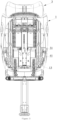
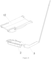
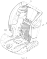
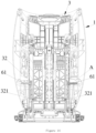
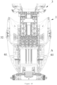
- Kindersicherheitssitz, aufweisend einen Sitzkörper und einen Fünfpunkt-Sicherheitsgurt, der an dem Sitzkörper angeordnet ist, wobei der Sitzkörper ein Gehäuse (1) aufweist, wobei der Fünfpunkt-Sicherheitsgurt einen Sicherheitsgurtverschluss aufweist, wobei das Gehäuse (1) integral mit einem Aufnahmeschlitz (11) versehen ist, der verwendet wird zum Aufnehmen des Sicherheitsgurtverschlusses, dadurch gekennzeichnet, dass
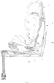
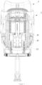
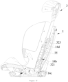
der Sitzkörper ferner eine Kopfstützenbaugruppe (3) aufweist, die am Gehäuse (1) in einer aufwärts-abwärts-verschiebbaren Weise angeordnet ist, wobei die Kopfstützenbaugruppe (3) eine vorbestimmte Position hat, und wobei, wenn der Sicherheitsgurtverschluss in dem Aufnahmeschlitz (11) angeordnet ist, es der Kopfstützenbaugruppe (3) ermöglicht ist, höher als die vorbestimmte Position zu sein. - Kindersicherheitssitz gemäß Anspruch 1, dadurch gekennzeichnet, dass der Kindersicherheitssitz einen ersten Verwendungszustand und einen zweiten Verwendungszustand hat, wobei im ersten Verwendungszustand die Kopfstützenbaugruppe (3) nicht höher als die vorbestimmte Position ist und der Sicherheitsgurtverschluss ständig außerhalb des Aufnahmeschlitzes (11) angeordnet ist, um die Verwendung des Fünfpunkt-Sicherheitsgurts zu erlauben, oder der Sicherheitsgurtverschluss nur dann außerhalb des Aufnahmeschlitzes (11) angeordnet ist, wenn die Kopfstützenbaugruppe (3) niedriger als die vorbestimmte Position ist, und der Sicherheitsgurtverschluss imstande ist, in den Aufnahmeschlitz (11) eingebracht zu werden, wenn die Kopfstützenbaugruppe (3) in der vorbestimmten Position ist, wobei im zweiten Verwendungszustand der Sicherheitsgurtverschluss im Aufnahmeschlitz (11) angeordnet ist und die Kopfstützenbaugruppe (3) höher als die vorbestimmte Position ist.
- Kindersitzsicherheitssitz gemäß Anspruch 2, dadurch gekennzeichnet, dass der Sitzkörper ferner aufweist einen Positionsbegrenzungs-Mechanismus zum Verhindern, dass die Kopfstützenbaugruppe (3) höher als die vorbestimmte Position ist, und ein Entriegelungselement (5) zum Freigeben der Positionsbegrenzung der Kopfstützenbaugruppe (3) und des Positionsbegrenzungs-Mechanismus, wobei das Entriegelungselement (5) an dem Gehäuse (1) verschiebbar angeordnet ist und ein Ende des Entriegelungselements (5) in dem Aufnahmeschlitz (11) bewegbar angeordnet ist, wobei, wenn der Kindersicherheitssitz von dem ersten Verwendungszustand in den zweiten Verwendungszustand überführt wird, der Sicherheitsgurtverschluss (2) in den Aufnahmeschlitz (11) eintritt und das eine Ende des Entriegelungselements (5) drückt, um die Positionsbegrenzung der Kopfstützenbaugruppe (3) und den Positionsbegrenzungs-Mechanismus freizugeben.
- Kindersicherheitssitz gemäß Anspruch 3, dadurch gekennzeichnet, dass das Entriegelungselement (5) an dem Gehäuse (1) in einer aufwärts-abwärts-verschiebbaren Weise angeordnet ist und ein unterer Endabschnitt des Entriegelungselements (5) in dem Aufnahmeschlitz (11) bewegbar angeordnet ist.
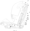
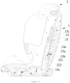
- Kindersicherheitssitz gemäß Anspruch 4, dadurch gekennzeichnet, dass die Kopfstützenbaugruppe (3) einen feststehenden Kopfstützenteil (31) aufweist, wobei der feststehende Kopfstützenteil (31) mit einer nach oben weisenden Positionsbegrenzungsfläche (311a) daran ausgebildet ist,wobei der Positionsbegrenzungs-Mechanismus einen ersten Verriegelungsstift-Sitz (4) aufweist, der an dem Gehäuse (1) (4) in einer links-rechts-verschiebbaren Weise angeordnet ist, wobei der erste Verriegelungsstift-Sitz (4) mit einem ersten Verriegelungsstift (41) versehen ist, der mit der Positionsbegrenzungsfläche (311a) zusammenwirkt, und wobei die Kopfstützenbaugruppe (3) in der vorbestimmten Position ist, wenn der erste Verriegelungsstift (41) gegen die Positionsbegrenzungsfläche (311a) drückt,wobei das Entriegelungselement (5) in einem engen Kontakt mit dem ersten Verriegelungsstift-Sitz (4) ist und wenigstens eine der Komponenten mit einer Entriegelungsschrägen (4a, 5a) versehen ist, welche die andere Komponente kontaktiert und dieser zusammenwirkt, und wobei die Entriegelungsschräge (4a, 5a) von links nach rechts graduell aufwärts oder abwärts geneigt ist,wobei, wenn der Kindersicherheitssitz im ersten Verwendungszustand ist, der erste Verriegelungsstift (41) direkt über der Positionsbegrenzungsfläche (311a) angeordnet ist oder gegen die Positionsbegrenzungsfläche (311a) drückt, wobei, wenn der Kindersicherheitssitz im zweiten Verwendungszustand ist, der erste Verriegelungsstift (41) auf der linken oder rechten Seite der Positionsbegrenzungsfläche (311a) angeordnet ist, um von der Positionsbegrenzungsfläche (311a) außer Eingriff zu gelangen.
- Kindersicherheitssitz gemäß Anspruch 5, dadurch gekennzeichnet, dass der feststehende Kopfstützenteil (31) mittels eines ersten Führungsschlitzes (311) daran offen ist, wobei sich der erste Führungsschlitz (311) entlang einer aufwärts-abwärts-Richtung erstreckt, wobei die Positionsbegrenzungsfläche (311a) an einer unteren Wand des ersten Führungsschlitzes (311) ausgebildet ist, wobei eine linke oder rechte Wand des ersten Führungsschlitzes (311) mittels einer Lücke (313) offen ist, in welche/aus welcher der erste Verriegelungsstift (41) hinein-/herausgelangen kann, wobei, wenn der Kindersicherheitssitz im ersten Verwendungszustand ist, der erste Verriegelungsstift (41) in den ersten Führungsschlitz (311) verschiebbar eingesetzt ist, wobei, wenn der Kindersicherheitssitz im zweiten Verwendungszustand ist, der erste Verriegelungsstift (41) außerhalb des ersten Führungsschlitzes (311) angeordnet ist.
- Kindersicherheitssitz gemäß Anspruch 6, dadurch gekennzeichnet, dass der feststehende Kopfstützenteil (31) ferner mittels eines zweiten Führungsschlitzes (312) daran offen ist, wobei der zweite Führungsschlitz (312) via die Lücke (313) in Kommunikation mit dem ersten Führungsschlitz (311) ist, wobei, wenn der Kindersicherheitssitz im zweiten Verwendungszustand ist, der erste Verriegelungsstift (41) in den zweiten Führungsschlitz (312) verschiebbar eingesetzt ist oder direkt unter dem zweiten Führungsschlitz (312) angeordnet ist.
- Kindersicherheitssitz gemäß Anspruch 5, dadurch gekennzeichnet, dass der Positionsbegrenzungs-Mechanismus ferner ein erstes Elastikelement (42) aufweist, das zwischen dem Gehäuse (1) und dem ersten Verriegelungsstift-Sitz (4) angeordnet ist.
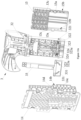
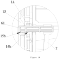
- Kindersicherungssitz gemäß Anspruch 4, dadurch gekennzeichnet, dass das Gehäuse (1) eine äußere Plattenabdeckung (14) und eine innere Plattenabdeckung (15) aufweist, die imstande ist, sich relativ zu der äußeren Plattenabdeckung (14) zu verschieben, wobei der Positionsbegrenzungs-Mechanismus aufweist einen ersten Positionsbegrenzungsabschnitt (15a), der an der inneren Plattenabdeckung (15) ausgebildet ist, und einen zweiten Positionsbegrenzungsabschnitt (14a), der an der äußeren Plattenabdeckung (14) ausgebildet ist, wobei der erste Positionsbegrenzungsabschnitt (15a) direkt unter dem zweiten Positionsbegrenzungsabschnitt (14a) angeordnet ist, wobei, wenn die Kopfstützenbaugruppe (3) in der vorbestimmten Position ist, der erste Positionsbegrenzungsabschnitt (15a) gegen den zweiten Positionsbegrenzungsabschnitt (14a) drückt, wobei der Sitzkörper ferner einen zweiten Verriegelungsstift (61) aufweist, wobei der zweite Verriegelungsstift (61) an dem zweiten Verriegelungsstift-Sitz (6) angeordnet ist, wobei das Entriegelungselement (7) in einem engen Kontakt mit dem zweiten Verriegelungsstift-Sitz (6) ist und wenigstens eine der Komponenten mit einer Entriegelungsschrägen versehen ist, welche die andere Komponente kontaktiert und mit dieser zusammenwirkt, wobei die Entriegelungsschräge von links nach rechts graduell aufwärts oder abwärts geneigt ist,wobei die äußere Plattenabdeckung (14) mit einem äußeren Verriegelungsschlitz versehen ist, in welchen der zweite Verriegelungsstift (61) eingesetzt ist, und wobei die innere Plattenabdeckung (15) mit einem inneren Verriegelungsschlitz versehen ist, in welchen der zweite Verriegelungsstift (61) eingesetzt ist,wobei die Kopfstützenbaugruppe (3) eine Kopfstütze (32) und einen innere-Plattenabdeckung-(15)-Verriegelungsstift aufweist, der imstande, in den inneren Verriegelungsschlitz eingesetzt zu sein,wobei, wenn der Kindersicherheitssitz im ersten Verwendungszustand ist, der innere-Plattenabdeckung-(15)-Verriegelungsstift in den inneren Verriegelungsschlitz eingesetzt ist, wobei die Kopfstützenbaugruppe (3) und die innere Plattenabdeckung (15) verbunden sind, um bezüglich der äußeren Plattenabdeckung (14) synchron verschiebbar zu sein, wobei, wenn der Kindersicherheitssitz im zweiten Verwendungszustand ist, der zweite Verriegelungsstift (61) in den inneren Verriegelungsschlitz und den äußeren Verriegelungsschlitz eingesetzt ist, sodass die innere Plattenabdeckung (15) und die äußere Plattenabdeckung verbunden sind und der innere-Plattenabdeckung-(15)-Verriegelungsstift aus dem inneren Verriegelungsschlitz herausgedrückt ist, wobei die Kopfstützenbaugruppe von der inneren Plattenabdeckung (15) außer Eingriff ist, um bezüglich der inneren Plattenabdeckung (15) und der äußeren Plattenabdeckung (14) aufwärts-abwärts-verschiebbar zu sein.
- Kindersicherheitssitz gemäß Anspruch 9, dadurch gekennzeichnet, dass ein oberer Endabschnitt des Entriegelungselements (7) mit einem geneigten Entriegelungsschlitz (7a) versehen ist, wobei der zweite Verriegelungsstift-Sitz (6) in den geneigten Entriegelungsschlitz (7a) verschiebbar eingesetzt ist, und wobei die Entriegelungsschräge an einer Wand des geneigten Entriegelungsschlitzes (7a) ausgebildet ist.
- Kindersicherheitssitz gemäß Anspruch 10, dadurch gekennzeichnet, dass die Anzahl des zweiten Verriegelungsstifts (61) zwei ist und sie in Intervallen links und rechts angeordnet sind, wobei die innere Plattenabdeckung (15) und die äußere Plattenabdeckung (14) zwischen den beiden zweiten Verriegelungsstiften (61) angeordnet sind, und wobei ein Abstand zwischen oberen Enden der geneigten Verriegelungsschlitze (7a) auf der linken und der rechten Seite kleiner ist als jener zwischen den unteren Enden davon.
- Kindersicherheitssitz gemäß Anspruch 9, dadurch gekennzeichnet, dass die Kopfstütze (32) mit einem ersten Montageschlitz versehen ist, wobei der innere-Plattenabdeckung-Verriegelungsstift (321) in dem ersten Montagschlitz verschiebbar angeordnet ist, und wobei zwischen einer Wand des ersten Montageschlitzes und der inneren Plattenabdeckung (15) ein zweites Elastikelement (322) bereitgestellt ist zum Einsetzen des innere-Plattenabdeckung-Verriegelungsstifts (321) in den inneren Verriegelungsschlitz (15b).
- Kindersicherheitssitz gemäß Anspruch 9, dadurch gekennzeichnet, dass der erste Positionsbegrenzungsabschnitt (15a) und der zweite Positionsbegrenzungsabschnitt (14a) jeweils Vorsprünge (323a) sind.
- Kindersicherheitssitz gemäß Anspruch 9, dadurch gekennzeichnet, dass ein zweiter Montageschlitz an der Kopfstütze (32) bereitgestellt ist, wobei der zweite Montageschlitz darin mit einem Positionierungsverriegelungsstift (323) versehen ist, der links-rechts-verschiebbar ist, wobei ein unterer Abschnitt der äußeren Plattenabdeckung (14) mit einer Mehrzahl von ersten Positionierungsschlitzen (14c) versehen ist, die aufwärts-abwärts im Abstand sind, wobei ein oberer Abschnitt der äußeren Plattenabdeckung (14) mit einer Mehrzahl von zweiten Positionierungsschlitzen (14d) versehen ist, die aufwärts-abwärts im Abstand sind, wobei die innere Plattenabdeckung (15) mit einer Mehrzahl von dritten Positionierungsschlitzen (15c) versehen ist, die aufwärts-abwärts im Abstand sind, und wobei die zweiten Positionierungsschlitze (14d) und die dritten Positionierungsschlitze (15c) zueinander korrespondieren, wobei, wenn der Kindersicherheitssitz im ersten Verwendungszustand ist, der Positionierungsverriegelungsstift (323) in irgendeinen der ersten Positionierungsschlitze (14c) eingesetzt ist, wobei, wenn der Kindersicherheitssitz im zweiten Verwendungszustand ist, die zweiten Positionierungsschlitze (14d) zu den korrespondierenden dritten Positionierungsschlitzen (15c) ausgerichtet sind und der Positionierungsverriegelungsstift (323) in irgendeinen der zweiten Positionierungsschlitze (14d) und den korrespondierenden dritten Positionierungsschlitz (15c) eingesetzt ist,
wobei, bevorzugt, die Kopfstützenbaugruppe (3) ferner eine Einstellhandhabe (33) aufweist, die aufwärts-abwärts-verschiebbar ist, wobei ein unterer Abschnitt der Einstellhandhabe (33) mit einem geneigten Einstellschlitz (331) versehen ist, und wobei der Positionierungsverriegelungsstift (323) mit einem Vorsprung (323a) versehen ist, der in den geneigten Einstellschlitz (331) verschiebbar eingesetzt ist. - Kindersicherheitssitz gemäß irgendeinem der Ansprüche 4-14, dadurch gekennzeichnet, dass zwischen dem Gehäuse (1) und dem Entriegelungselement (5) ein drittes Elastikelement (51, 71) bereitgestellt ist zum Antreiben des Entriegelungselements (5, 7), um sich aufwärts zu bewegen.
Applications Claiming Priority (2)
| Application Number | Priority Date | Filing Date | Title |
|---|---|---|---|
| CN201811024985.6A CN109017474B (zh) | 2018-09-04 | 2018-09-04 | 一种儿童安全座椅 |
| PCT/CN2018/119769 WO2020048032A1 (zh) | 2018-09-04 | 2018-12-07 | 一种儿童安全座椅 |
Publications (4)
| Publication Number | Publication Date |
|---|---|
| EP3848239A1 EP3848239A1 (de) | 2021-07-14 |
| EP3848239A4 EP3848239A4 (de) | 2022-06-08 |
| EP3848239C0 EP3848239C0 (de) | 2025-03-26 |
| EP3848239B1 true EP3848239B1 (de) | 2025-03-26 |
Family
ID=64623226
Family Applications (1)
| Application Number | Title | Priority Date | Filing Date |
|---|---|---|---|
| EP18932840.4A Active EP3848239B1 (de) | 2018-09-04 | 2018-12-07 | Kindersicherheitssitz |
Country Status (5)
| Country | Link |
|---|---|
| US (1) | US11413992B2 (de) |
| EP (1) | EP3848239B1 (de) |
| JP (1) | JP7111890B2 (de) |
| CN (1) | CN109017474B (de) |
| WO (1) | WO2020048032A1 (de) |
Families Citing this family (3)
| Publication number | Priority date | Publication date | Assignee | Title |
|---|---|---|---|---|
| CN117962713A (zh) * | 2020-10-13 | 2024-05-03 | 宝钜瑞士股份有限公司 | 头靠高度调节方法 |
| CN115366759B (zh) * | 2021-05-21 | 2025-03-18 | 明门瑞士股份有限公司 | 儿童安全座椅及其支撑组件 |
| WO2025141644A1 (ja) * | 2023-12-25 | 2025-07-03 | コンビ株式会社 | チャイルドシート |
Family Cites Families (22)
| Publication number | Priority date | Publication date | Assignee | Title |
|---|---|---|---|---|
| US6491348B1 (en) * | 2000-07-31 | 2002-12-10 | Cosco Management, Inc. | Child vehicle seat with child-restraint harness adjustment mechanism |
| JP2004359193A (ja) | 2003-06-09 | 2004-12-24 | Aprica Kassai Inc | 着脱式チャイルドシート |
| ES1061044Y (es) * | 2005-09-12 | 2006-04-01 | Jane Sa | Asiento infantil para automoviles. |
| CN201176134Y (zh) | 2008-03-14 | 2009-01-07 | 林锡雷 | 可连动调节的车用儿童安全座椅 |
| US8944503B2 (en) * | 2009-01-27 | 2015-02-03 | Graco Children's Products Inc. | Child safety seat harness tensioning device |
| NL1036865C2 (en) * | 2009-04-16 | 2010-10-19 | Maxi Miliaan Bv | Child vehicle seat. |
| DE102009017601B4 (de) * | 2009-04-16 | 2011-06-22 | RECARO GmbH & Co. KG, 73230 | Fahrzeugkindersitz |
| CN104742765B (zh) * | 2014-02-28 | 2017-09-19 | 伯瑞苔斯罗默儿童安全有限公司 | 儿童安全座椅 |
| DE102015109108A1 (de) * | 2015-06-09 | 2016-12-15 | Recaro Child Safety Gmbh & Co. Kg | Kindersitzvorrichtung |
| US10124702B2 (en) * | 2015-10-30 | 2018-11-13 | Dorel Juvenile Group, Inc. | Child restraint with belt management system |
| CN105857131B (zh) | 2016-06-18 | 2018-05-29 | 宁波市博林日用品制造有限公司 | 一种汽车儿童安全座椅 |
| CN107539173B (zh) * | 2016-06-23 | 2021-06-25 | 瑞典雄霸安全制品有限公司 | 具有锁定机构的束带系统 |
| CN106314221B (zh) * | 2016-08-29 | 2018-07-10 | 好孩子儿童用品有限公司 | 一种儿童安全座椅 |
| CN106143226B (zh) * | 2016-08-29 | 2018-12-21 | 好孩子儿童用品有限公司 | 一种儿童安全座椅 |
| US10266077B2 (en) | 2016-11-11 | 2019-04-23 | Wonderland Switzerland Ag | Child safety seat |
| WO2018148569A1 (en) | 2017-02-09 | 2018-08-16 | Dorel Juvenile Group, Inc. | Juvenile vehicle seat with adjustable headrest |
| CN107527917B (zh) * | 2017-08-31 | 2019-12-10 | 上海华虹宏力半导体制造有限公司 | 1.5t耗尽型sonos非挥发性存储器及其制造方法 |
| CN107627916A (zh) | 2017-09-01 | 2018-01-26 | 浙江乐优贝汽车用品有限公司 | 儿童座椅 |
| ES2875560T3 (es) * | 2017-09-06 | 2021-11-10 | Britax Roemer Kindersicherheit Gmbh | Asiento de seguridad para niños con mecanismo de ajuste de la altura del reposacabezas |
| CN107627917B (zh) | 2017-10-11 | 2024-03-19 | 宁波惠尔顿婴童安全科技股份有限公司 | 一种儿童安全座椅卡扣及安全带收纳结构 |
| US10730414B2 (en) * | 2017-12-11 | 2020-08-04 | Evenflo Company, Inc. | Adjustable headrest for child car seat |
| CN209208542U (zh) * | 2018-09-04 | 2019-08-06 | 好孩子儿童用品有限公司 | 一种儿童安全座椅 |
-
2018
- 2018-09-04 CN CN201811024985.6A patent/CN109017474B/zh active Active
- 2018-12-07 US US17/273,145 patent/US11413992B2/en active Active
- 2018-12-07 WO PCT/CN2018/119769 patent/WO2020048032A1/zh not_active Ceased
- 2018-12-07 EP EP18932840.4A patent/EP3848239B1/de active Active
- 2018-12-07 JP JP2021512547A patent/JP7111890B2/ja active Active
Also Published As
| Publication number | Publication date |
|---|---|
| JP7111890B2 (ja) | 2022-08-02 |
| CN109017474B (zh) | 2023-05-23 |
| EP3848239A4 (de) | 2022-06-08 |
| US20210323450A1 (en) | 2021-10-21 |
| EP3848239C0 (de) | 2025-03-26 |
| EP3848239A1 (de) | 2021-07-14 |
| CN109017474A (zh) | 2018-12-18 |
| WO2020048032A1 (zh) | 2020-03-12 |
| US11413992B2 (en) | 2022-08-16 |
| JP2021535861A (ja) | 2021-12-23 |
Similar Documents
| Publication | Publication Date | Title |
|---|---|---|
| CA2763992C (en) | Child safety seat assembly | |
| US4376551A (en) | Child care seat and restraining system | |
| EP3848239B1 (de) | Kindersicherheitssitz | |
| KR101997547B1 (ko) | 차일드 시트 | |
| EP2407341B1 (de) | Kindersicherheitssitzanordnung | |
| EP1904335B1 (de) | Kindersicherheitssitz | |
| CA3055062C (en) | Child restraint system and child restraint carrier thereof | |
| CA2010641C (en) | Vehicle seat for a child | |
| US4909574A (en) | Child's car seat restraint system | |
| CN107618406B (zh) | 儿童安全座椅 | |
| US5690382A (en) | Adjustable child-restraint shield | |
| KR200438960Y1 (ko) | 유아용 카시트 | |
| EP0155784A2 (de) | Fahrzeugsitzausrüstung für Kinder | |
| KR20180099688A (ko) | 차량 시트에 부착하기 위한 차일드 시트 | |
| US7448690B2 (en) | Child safety seat with emergency harness release | |
| CN209208542U (zh) | 一种儿童安全座椅 | |
| CN107599905B (zh) | 一种儿童安全座椅头靠调节机构 | |
| CN218929265U (zh) | 汽车儿童安全座椅用上拉带组件及儿童安全座椅 | |
| CN215904358U (zh) | 儿童汽车安全座椅 | |
| US20090134678A1 (en) | Child safety seat with emergency harness release | |
| CN216508020U (zh) | 一种安全座椅侧保护机构及儿童安全座椅 | |
| CN223533529U (zh) | 安全搭扣、安全束缚系统及儿童用品 | |
| KR100635866B1 (ko) | 시트체가 곡선운동이 유도되는 유아용 자동차 안전시트 | |
| CN116279020B (zh) | 汽车儿童安全座椅用上拉带组件及儿童安全座椅 | |
| CN215126509U (zh) | 一种婴儿餐椅的餐盘拉手卡扣机构 |
Legal Events
| Date | Code | Title | Description |
|---|---|---|---|
| STAA | Information on the status of an ep patent application or granted ep patent |
Free format text: STATUS: THE INTERNATIONAL PUBLICATION HAS BEEN MADE |
|
| PUAI | Public reference made under article 153(3) epc to a published international application that has entered the european phase |
Free format text: ORIGINAL CODE: 0009012 |
|
| STAA | Information on the status of an ep patent application or granted ep patent |
Free format text: STATUS: REQUEST FOR EXAMINATION WAS MADE |
|
| 17P | Request for examination filed |
Effective date: 20210303 |
|
| AK | Designated contracting states |
Kind code of ref document: A1 Designated state(s): AL AT BE BG CH CY CZ DE DK EE ES FI FR GB GR HR HU IE IS IT LI LT LU LV MC MK MT NL NO PL PT RO RS SE SI SK SM TR |
|
| DAV | Request for validation of the european patent (deleted) | ||
| DAX | Request for extension of the european patent (deleted) | ||
| A4 | Supplementary search report drawn up and despatched |
Effective date: 20220509 |
|
| RIC1 | Information provided on ipc code assigned before grant |
Ipc: B60N 2/28 20060101AFI20220502BHEP |
|
| GRAP | Despatch of communication of intention to grant a patent |
Free format text: ORIGINAL CODE: EPIDOSNIGR1 |
|
| STAA | Information on the status of an ep patent application or granted ep patent |
Free format text: STATUS: GRANT OF PATENT IS INTENDED |
|
| INTG | Intention to grant announced |
Effective date: 20241119 |
|
| GRAS | Grant fee paid |
Free format text: ORIGINAL CODE: EPIDOSNIGR3 |
|
| GRAA | (expected) grant |
Free format text: ORIGINAL CODE: 0009210 |
|
| STAA | Information on the status of an ep patent application or granted ep patent |
Free format text: STATUS: THE PATENT HAS BEEN GRANTED |
|
| AK | Designated contracting states |
Kind code of ref document: B1 Designated state(s): AL AT BE BG CH CY CZ DE DK EE ES FI FR GB GR HR HU IE IS IT LI LT LU LV MC MK MT NL NO PL PT RO RS SE SI SK SM TR |
|
| REG | Reference to a national code |
Ref country code: GB Ref legal event code: FG4D |
|
| REG | Reference to a national code |
Ref country code: CH Ref legal event code: EP |
|
| REG | Reference to a national code |
Ref country code: DE Ref legal event code: R096 Ref document number: 602018080606 Country of ref document: DE |
|
| REG | Reference to a national code |
Ref country code: IE Ref legal event code: FG4D |
|
| U01 | Request for unitary effect filed |
Effective date: 20250424 |
|
| U07 | Unitary effect registered |
Designated state(s): AT BE BG DE DK EE FI FR IT LT LU LV MT NL PT RO SE SI Effective date: 20250502 |
|
| PG25 | Lapsed in a contracting state [announced via postgrant information from national office to epo] |
Ref country code: RS Free format text: LAPSE BECAUSE OF FAILURE TO SUBMIT A TRANSLATION OF THE DESCRIPTION OR TO PAY THE FEE WITHIN THE PRESCRIBED TIME-LIMIT Effective date: 20250626 |
|
| PG25 | Lapsed in a contracting state [announced via postgrant information from national office to epo] |
Ref country code: NO Free format text: LAPSE BECAUSE OF FAILURE TO SUBMIT A TRANSLATION OF THE DESCRIPTION OR TO PAY THE FEE WITHIN THE PRESCRIBED TIME-LIMIT Effective date: 20250626 |
|
| PG25 | Lapsed in a contracting state [announced via postgrant information from national office to epo] |
Ref country code: HR Free format text: LAPSE BECAUSE OF FAILURE TO SUBMIT A TRANSLATION OF THE DESCRIPTION OR TO PAY THE FEE WITHIN THE PRESCRIBED TIME-LIMIT Effective date: 20250326 |
|
| PG25 | Lapsed in a contracting state [announced via postgrant information from national office to epo] |
Ref country code: GR Free format text: LAPSE BECAUSE OF FAILURE TO SUBMIT A TRANSLATION OF THE DESCRIPTION OR TO PAY THE FEE WITHIN THE PRESCRIBED TIME-LIMIT Effective date: 20250627 |
|
| PG25 | Lapsed in a contracting state [announced via postgrant information from national office to epo] |
Ref country code: SM Free format text: LAPSE BECAUSE OF FAILURE TO SUBMIT A TRANSLATION OF THE DESCRIPTION OR TO PAY THE FEE WITHIN THE PRESCRIBED TIME-LIMIT Effective date: 20250326 |
|
| PG25 | Lapsed in a contracting state [announced via postgrant information from national office to epo] |
Ref country code: ES Free format text: LAPSE BECAUSE OF FAILURE TO SUBMIT A TRANSLATION OF THE DESCRIPTION OR TO PAY THE FEE WITHIN THE PRESCRIBED TIME-LIMIT Effective date: 20250326 |
|
| PG25 | Lapsed in a contracting state [announced via postgrant information from national office to epo] |
Ref country code: PL Free format text: LAPSE BECAUSE OF FAILURE TO SUBMIT A TRANSLATION OF THE DESCRIPTION OR TO PAY THE FEE WITHIN THE PRESCRIBED TIME-LIMIT Effective date: 20250326 |
|
| PG25 | Lapsed in a contracting state [announced via postgrant information from national office to epo] |
Ref country code: SK Free format text: LAPSE BECAUSE OF FAILURE TO SUBMIT A TRANSLATION OF THE DESCRIPTION OR TO PAY THE FEE WITHIN THE PRESCRIBED TIME-LIMIT Effective date: 20250326 |
|
| PG25 | Lapsed in a contracting state [announced via postgrant information from national office to epo] |
Ref country code: IS Free format text: LAPSE BECAUSE OF FAILURE TO SUBMIT A TRANSLATION OF THE DESCRIPTION OR TO PAY THE FEE WITHIN THE PRESCRIBED TIME-LIMIT Effective date: 20250726 |
|
| U20 | Renewal fee for the european patent with unitary effect paid |
Year of fee payment: 8 Effective date: 20251209 |
|
| PG25 | Lapsed in a contracting state [announced via postgrant information from national office to epo] |
Ref country code: CZ Free format text: LAPSE BECAUSE OF FAILURE TO SUBMIT A TRANSLATION OF THE DESCRIPTION OR TO PAY THE FEE WITHIN THE PRESCRIBED TIME-LIMIT Effective date: 20250326 |
|
| PLBE | No opposition filed within time limit |
Free format text: ORIGINAL CODE: 0009261 |
|
| STAA | Information on the status of an ep patent application or granted ep patent |
Free format text: STATUS: NO OPPOSITION FILED WITHIN TIME LIMIT |
|
| REG | Reference to a national code |
Ref country code: CH Ref legal event code: L10 Free format text: ST27 STATUS EVENT CODE: U-0-0-L10-L00 (AS PROVIDED BY THE NATIONAL OFFICE) Effective date: 20260211 |