EP3848126A1 - Pressurizing centrifugal dehydrator - Google Patents
Pressurizing centrifugal dehydrator Download PDFInfo
- Publication number
- EP3848126A1 EP3848126A1 EP20848781.9A EP20848781A EP3848126A1 EP 3848126 A1 EP3848126 A1 EP 3848126A1 EP 20848781 A EP20848781 A EP 20848781A EP 3848126 A1 EP3848126 A1 EP 3848126A1
- Authority
- EP
- European Patent Office
- Prior art keywords
- basket
- blocking barrier
- centrifugal dehydrator
- outer basket
- supplying
- Prior art date
- Legal status (The legal status is an assumption and is not a legal conclusion. Google has not performed a legal analysis and makes no representation as to the accuracy of the status listed.)
- Granted
Links
Images


Classifications
-
- F—MECHANICAL ENGINEERING; LIGHTING; HEATING; WEAPONS; BLASTING
- F26—DRYING
- F26B—DRYING SOLID MATERIALS OR OBJECTS BY REMOVING LIQUID THEREFROM
- F26B5/00—Drying solid materials or objects by processes not involving the application of heat
- F26B5/04—Drying solid materials or objects by processes not involving the application of heat by evaporation or sublimation of moisture under reduced pressure, e.g. in a vacuum
- F26B5/041—Drying solid materials or objects by processes not involving the application of heat by evaporation or sublimation of moisture under reduced pressure, e.g. in a vacuum for drying flowable materials, e.g. suspensions, bulk goods, in a continuous operation, e.g. with locks or other air tight arrangements for charging/discharging
-
- B—PERFORMING OPERATIONS; TRANSPORTING
- B04—CENTRIFUGAL APPARATUS OR MACHINES FOR CARRYING-OUT PHYSICAL OR CHEMICAL PROCESSES
- B04B—CENTRIFUGES
- B04B15/00—Other accessories for centrifuges
-
- B—PERFORMING OPERATIONS; TRANSPORTING
- B04—CENTRIFUGAL APPARATUS OR MACHINES FOR CARRYING-OUT PHYSICAL OR CHEMICAL PROCESSES
- B04B—CENTRIFUGES
- B04B3/00—Centrifuges with rotary bowls in which solid particles or bodies become separated by centrifugal force and simultaneous sifting or filtering
- B04B3/02—Centrifuges with rotary bowls in which solid particles or bodies become separated by centrifugal force and simultaneous sifting or filtering discharging solid particles from the bowl by means coaxial with the bowl axis and moving to and fro, i.e. push-type centrifuges
-
- B—PERFORMING OPERATIONS; TRANSPORTING
- B04—CENTRIFUGAL APPARATUS OR MACHINES FOR CARRYING-OUT PHYSICAL OR CHEMICAL PROCESSES
- B04B—CENTRIFUGES
- B04B3/00—Centrifuges with rotary bowls in which solid particles or bodies become separated by centrifugal force and simultaneous sifting or filtering
-
- B—PERFORMING OPERATIONS; TRANSPORTING
- B04—CENTRIFUGAL APPARATUS OR MACHINES FOR CARRYING-OUT PHYSICAL OR CHEMICAL PROCESSES
- B04B—CENTRIFUGES
- B04B1/00—Centrifuges with rotary bowls provided with solid jackets for separating predominantly liquid mixtures with or without solid particles
-
- B—PERFORMING OPERATIONS; TRANSPORTING
- B04—CENTRIFUGAL APPARATUS OR MACHINES FOR CARRYING-OUT PHYSICAL OR CHEMICAL PROCESSES
- B04B—CENTRIFUGES
- B04B11/00—Feeding, charging, or discharging bowls
-
- B—PERFORMING OPERATIONS; TRANSPORTING
- B04—CENTRIFUGAL APPARATUS OR MACHINES FOR CARRYING-OUT PHYSICAL OR CHEMICAL PROCESSES
- B04B—CENTRIFUGES
- B04B11/00—Feeding, charging, or discharging bowls
- B04B11/02—Continuous feeding or discharging; Control arrangements therefor
-
- B—PERFORMING OPERATIONS; TRANSPORTING
- B04—CENTRIFUGAL APPARATUS OR MACHINES FOR CARRYING-OUT PHYSICAL OR CHEMICAL PROCESSES
- B04B—CENTRIFUGES
- B04B15/00—Other accessories for centrifuges
- B04B15/12—Other accessories for centrifuges for drying or washing the separated solid particles
-
- B—PERFORMING OPERATIONS; TRANSPORTING
- B04—CENTRIFUGAL APPARATUS OR MACHINES FOR CARRYING-OUT PHYSICAL OR CHEMICAL PROCESSES
- B04B—CENTRIFUGES
- B04B7/00—Elements of centrifuges
- B04B7/08—Rotary bowls
- B04B7/12—Inserts, e.g. armouring plates
-
- F—MECHANICAL ENGINEERING; LIGHTING; HEATING; WEAPONS; BLASTING
- F26—DRYING
- F26B—DRYING SOLID MATERIALS OR OBJECTS BY REMOVING LIQUID THEREFROM
- F26B21/00—Arrangements for supplying or controlling air or other gases for drying solid materials or objects
- F26B21/001—Air generating units, e.g. movable or independent of drying enclosure
-
- F—MECHANICAL ENGINEERING; LIGHTING; HEATING; WEAPONS; BLASTING
- F26—DRYING
- F26B—DRYING SOLID MATERIALS OR OBJECTS BY REMOVING LIQUID THEREFROM
- F26B25/00—Details of general application not covered by group F26B21/00 or F26B23/00
- F26B25/001—Handling, e.g. loading or unloading arrangements
- F26B25/002—Handling, e.g. loading or unloading arrangements for bulk goods
-
- F—MECHANICAL ENGINEERING; LIGHTING; HEATING; WEAPONS; BLASTING
- F26—DRYING
- F26B—DRYING SOLID MATERIALS OR OBJECTS BY REMOVING LIQUID THEREFROM
- F26B25/00—Details of general application not covered by group F26B21/00 or F26B23/00
- F26B25/06—Chambers, containers, or receptacles
- F26B25/14—Chambers, containers, receptacles of simple construction
- F26B25/18—Chambers, containers, receptacles of simple construction mainly open, e.g. dish, tray, pan, rack
-
- F—MECHANICAL ENGINEERING; LIGHTING; HEATING; WEAPONS; BLASTING
- F26—DRYING
- F26B—DRYING SOLID MATERIALS OR OBJECTS BY REMOVING LIQUID THEREFROM
- F26B3/00—Drying solid materials or objects by processes involving the application of heat
- F26B3/02—Drying solid materials or objects by processes involving the application of heat by convection, i.e. heat being conveyed from a heat source to the materials or objects to be dried by a gas or vapour, e.g. air
- F26B3/06—Drying solid materials or objects by processes involving the application of heat by convection, i.e. heat being conveyed from a heat source to the materials or objects to be dried by a gas or vapour, e.g. air the gas or vapour flowing through the materials or objects to be dried
-
- F—MECHANICAL ENGINEERING; LIGHTING; HEATING; WEAPONS; BLASTING
- F26—DRYING
- F26B—DRYING SOLID MATERIALS OR OBJECTS BY REMOVING LIQUID THEREFROM
- F26B5/00—Drying solid materials or objects by processes not involving the application of heat
- F26B5/08—Drying solid materials or objects by processes not involving the application of heat by centrifugal treatment
Definitions
- the present invention relates to a pressurizing centrifugal dehydrator for removing moisture, and more particularly, to a pressurizing centrifugal dehydrator in which gas is injected into a basket in a state where the basket is airtight to improve dehydration performance using a pressurization force of the gas.
- a centrifugal dehydrator In a case of producing a polymer using an emulsion polymerization process, removal of moisture included in slurry generated after polymerization is a main issue.
- a centrifugal dehydrator In the existing polymer producing process, a centrifugal dehydrator is generally used to primarily remove moisture, and finally, remaining moisture is completely removed through a drying process after centrifugal dehydration.
- a pusher (push type) centrifugal dehydrator is used for a continuous process configuration.
- the pusher centrifugal dehydrator may be operated at a high speed to apply a high centrifugal force, and may be operated in a continuous process. Therefore, the pusher centrifugal dehydrator has been adopted and used in multiple processes.
- the pusher centrifugal dehydrator has a problem that a pipe for supplying slurry or washing water extends up to an inner basket, and thus pressure formation in the centrifugal dehydrator is hindered.
- a moisture content at the latter stage of the pusher centrifugal dehydrator depends on a characteristic (size or hydrophilicity) of a particle, and in a case where the size of a particle needs to be small for compounding, a moisture content is increased, which results in an increase in load in the drying process.
- the present invention has been made in an effort to solve the above-described problems according to the related art, and an object of the present invention is to provide a pressurizing centrifugal dehydrator in which gas is injected into a basket in a state where the basket is airtight to improve dehydration performance using a pressurization force of the gas.
- the present invention provides a pressurizing centrifugal dehydrator for removing moisture, including: an inner basket into which slurry is introduced; an outer basket surrounding the inner basket; a blocking barrier disposed in the outer basket; and a gas supplying portion for supplying gas into the inner basket or the outer basket, wherein a dehydration product is positioned between an outer circumference of the blocking barrier and an inner side of the outer basket to maintain airtightness of the outer basket.
- a gas supplying portion hole through which the gas supplying portion penetrates is formed in the blocking barrier.
- a slurry supplying portion hole through which a slurry supplying portion for supplying the slurry to the inner basket penetrates is formed in the blocking barrier.
- a washing water supplying portion hole through which a washing water supplying portion for supplying washing water to the inner basket penetrates is formed in the blocking barrier.
- the dehydration product positioned between the outer circumference of the blocking barrier and the inner side of the outer basket is discharged due to a dehydration product pushed from an inside of the outer basket.
- the dehydration product is continuously discharged by passing between the outer circumference of the blocking barrier and the inner side of the outer basket.
- the blocking barrier includes: a blocking barrier rotating portion that is fixed to the outer basket and rotates together with the outer basket; a blocking barrier fixing portion that is disposed inside the blocking barrier rotating portion and is fixed; and a rotating-fixing connection portion disposed between the blocking barrier rotating portion and the blocking barrier fixing portion.
- the rotating-fixing connection portion fixes the blocking barrier fixing portion while allowing rotation of the blocking barrier rotating portion.
- an inclined portion is formed in the blocking barrier rotating portion.
- gas can be injected into the basket by the gas supplying portion in a state where the basket is airtight due to the blocking barrier, such that it is possible to significantly improve dehydration performance using a pressurization force of the gas, as compared with the centrifugal dehydrator according to the related art.
- a pressurization centrifugal dehydration technique can be applied while maintaining the components of the centrifugal dehydrator according to the related art without any change. Therefore, an existing device is reusable.
- the centrifugal dehydrator 20 includes a dehydrator case 1, an inner basket 3 into which slurry is introduced, an outer basket 2 surrounding the inner basket 2, an outer basket shaft 4, an inner basket shaft 5, a slurry dispersing plate 6, a slurry discharging portion 7, a dehydration and washing water treatment region 8, a dehydration product treatment region 9, a washing water supplying portion 10, and a slurry supplying portion 11.
- the centrifugal dehydrator 20 may perform removal of moisture from polymer slurry and washing with washing water at the same time in a polymer producing process, and thus has been commonly used in the relevant field.
- centrifugal force may be provided by the centrifugal dehydrator 20, and thus it is difficult to decrease a moisture content of a product to below a predetermined value, which is problematic.
- the centrifugal dehydrator 20 has a structural characteristic in which slurry is supplied to the inner basket 3 through the slurry supplying portion 11, moisture is removed from the slurry, and then a dehydration product obtained by the removal of the moisture is discharged to the outside through the outer basket 2 and the dehydration product treatment region 9. Therefore, it is not possible to maintain airtightness of the basket, and it is thus not possible to perform pressurization by injecting gas into the basket.
- a pressurizing centrifugal dehydrator 100 according to the present invention a pressurization centrifugal dehydration technique can be applied while maintaining the above-described components of the centrifugal dehydrator 20 according to the related art without any change. Therefore, an existing device is reusable. Accordingly, for the pressurizing centrifugal dehydrator 100 according to the present invention, reference numerals of the components of the centrifugal dehydrator 20 according to the related art in Fig. 4 are used as they are.
- the pressurizing centrifugal dehydrator 100 according to the present invention will be described with reference to FIG. 1 .
- FIG. 1 only reference numerals of main components of the pressurizing centrifugal dehydrator 100 according to the present invention are illustrated.
- the pressurizing centrifugal dehydrator 100 for removing moisture includes an inner basket 3 into which slurry is introduced, an outer basket 2 surrounding the inner basket, a blocking barrier 30 disposed in the outer basket, and a gas supplying portion 40 for supplying gas into the inner basket 3 or outer basket 2.
- a dehydration product 200 can be positioned between an outer circumference of the blocking barrier 30 and an inner side of the outer basket 2 to maintain airtightness of the outer basket 2.
- the pressurizing centrifugal dehydrator 100 can include a slurry supplying portion 11 for supplying the slurry to the inner basket.
- the slurry introduced through the slurry supplying portion 11 is discharged to the inner basket 3 through a slurry discharging portion 7, and the slurry discharged through the slurry discharging portion 7 can be disposed in the inner basket 3 by a slurry dispersing plate 6.
- moisture is removed from the slurry by a centrifugal force of the inner basket 3 and the outer basket 2 caused by rotation of an inner basket shaft 5 and an outer basket shaft 4, and the removed moisture (dehydration) can pass through the inner basket 3 and the outer basket 2 and be discharged through a dehydration and washing water treatment region 8.
- the dehydration product 200 is continuously pushed out along an inner circumferential surface of the inner basket 3 around the inner basket shaft 5 of the inner basket 3 due to reciprocation of the inner basket shaft 5 and the outer basket shaft 4, and the pushed-out dehydration product 200 can be pushed toward between the outer circumference of the blocking barrier 30 and the inner side of the outer basket 2 to move to the dehydration product treatment region 9 and be discharged to the outside.
- the length between the outer circumference of the blocking barrier 30 and the inner side of the outer basket 2 can be smaller than the height of the dehydration product 200 accumulated along an inner circumferential surface of the outer basket 2 around the outer basket shaft 4 of the outer basket 2. In this case, airtightness between the outer circumference of the blocking barrier 30 and the inner side of the outer basket 2 can be maintained due to the dehydration product 200 accumulated along the inner circumferential surface of the outer basket 2.
- the length of a region adjacent to the outer circumference of the blocking barrier 30 and the inner side of the outer basket 2 can be larger than the height of the dehydration product 200 accumulated along an inner circumferential surface of the outer basket 2 around the outer basket shaft 4 of the outer basket 2. In this case, it is possible to further increase the airtightness of the outer basket 2.
- gas is supplied to the inner basket 3 or outer basket 2 through the gas supplying portion 40 to pressurize the inside of the basket (inner and outer baskets).
- gas supplying portion 40 to pressurize the inside of the basket (inner and outer baskets).
- the dehydration product 200 can be positioned between the blocking barrier 30 and the outer basket 2 to block the gas in the basket (inner and outer baskets) from being leaked.
- the gas is supplied to the inner basket 3 or outer basket 2 in an airtight state, since moisture that is not removable only with the centrifugal force and thus remains in the dehydration product 200 can be additionally removed by the pressurization force of the supplied gas, dehydration performance can be significantly improved, as compared with the centrifugal dehydrator 20 according to the related art. That is, as two forces, the centrifugal force and the pressurization force, are applied at the same time, the dehydration performance can be improved.
- FIG. 1 illustrates a case of supplying, by the gas supplying portion 40, the gas to the inner basket 3, the gas can be supplied to the inner basket 3, the outer basket 2, or both of the inner basket 3 and the outer basket 2.
- the dehydration product 200 positioned between the blocking barrier 30 and the outer basket 2 can be discharged by a dehydration product 200 pushed from the inside of the outer basket.
- the discharge of the dehydration product 200 positioned between the outer circumference of the blocking barrier 30 and the inner side of the outer basket 2 can mean that a process, in which the dehydration product 200 does not remain between the outer circumference of the blocking barrier 30 and the inner side of the outer basket 2, but is discharged by being pushed by another dehydration product 200 pushed from the inside of the outer basket 2, and the another dehydration product 200 pushed from the inside of the outer basket 2 is positioned between the blocking barrier 30 and the outer basket 2, is repeated, and thus the dehydration product 200 always exists between the blocking barrier 30 and the outer basket 2.
- the process in which the dehydration product 200 is discharged by being pushed by another dehydration product 200 pushed from the inside of the outer basket 2, and the another dehydration product 200 pushed from the inside of the outer basket 2 is positioned between the blocking barrier 30 and the outer basket 2, is repeated, such that the dehydration product 200 can be continuously discharged by passing between the outer circumference of the blocking barrier 30 and the inner side of the outer basket 2.
- the blocking barrier 30 will be described in more detail with reference to FIGS. 1 and 2 .
- the blocking barrier 30 includes a blocking barrier rotating portion 62 that is fixed to the outer basket 2 and rotates together with the outer basket 2, a blocking barrier fixing portion 64 that is disposed in the blocking barrier rotating portion 62 and is fixed without rotating, and a rotating-fixing connection portion 66 disposed between the blocking barrier rotating portion 62 and the blocking barrier fixing portion 64.
- the blocking barrier 30 can be separated into the blocking barrier rotating portion 62 that rotates, and the blocking barrier fixing portion 64 that is fixed without rotating.
- the blocking barrier rotating portion 62 rotates together with the outer basket 2, thereby minimizing friction caused by rotation of the dehydration product 200.
- the blocking barrier fixing portion 64 can be fixed to the slurry supplying portion 11 or can be fixed to another pipe to prevent the blocking barrier 30 from being pushed by the discharged dehydration product 200 and escaping to the outside.
- a fixing target of the blocking barrier fixing portion 64 is not limited.
- the rotating-fixing connection portion 66 connects the blocking barrier rotating portion 62 and the blocking barrier fixing portion 64, and parts such as a bearing and a roller can be used.
- the rotating-fixing connection portion 66 is not limited thereto. As such, as the rotating-fixing connection portion 66 is provided between the blocking barrier rotating portion 62 and the blocking barrier fixing portion 64, the blocking barrier rotating portion 62 rotates together with the outer basket 2, and the rotation is transferred to the rotating-fixing connection portion 66.
- the blocking barrier fixing portion 64 can be fixed.
- an inclined portion 68 can be formed in the blocking barrier rotating portion 62.
- the inclined portion 68 enables smoother introduction of the dehydration product 200 between the blocking barrier rotating portion 62 and the outer basket 2, such that airtightness between the blocking barrier rotating portion 62 and the outer basket 2 is improved. That is, the inclined portion 68 serves as a guide portion.
- the dehydration product 200 can be continuously supplied to a dehydration product discharging portion 52 by a force in an axial direction and then discharged.
- the blocking barrier rotating portion 62 can protrude from the outer basket 2 in an axial direction of the outer basket 2 (in FIG. 1 , the blocking barrier rotating portion 62 protrudes from the outer basket 2 to the right side). In this case, it is possible to more effectively maintain airtightness of the outer basket 2 and guide the dehydration product 200 moving between the outer circumference of the blocking barrier 30 and the inner side of the outer basket 2 to be discharged to the outside through the dehydration product discharging portion 52.
- a slurry supplying portion hole 34 through which the slurry supplying portion 11 penetrates, a washing water supplying portion hole 36 through which a washing water supplying portion 10 penetrates, and a gas supplying portion hole 38 which communicates with the gas supplying portion 40 can be formed.
- the gas supplying portion hole 38, the slurry supplying portion hole 34, and the washing water supplying portion hole 36 can be sequentially illustrated from top to bottom in FIG. 2 , and a sequence and arrangement thereof can vary. Further, in a case where an additional pipe is provided in the centrifugal dehydrator 20 according to the related art, a hole through which the corresponding pipe can penetrate can be additionally formed in the blocking barrier 30. Accordingly, the pressurization centrifugal dehydration technique can be applied while maintaining the components of the centrifugal dehydrator 20 according to the related art without any change. Therefore, an existing device is reusable.
- FIG. 3 illustrates a flow of gas to a moisture discharging portion 50, and a flow of the dehydration product 200 to the dehydration product discharging portion 52.
- the dehydration product 200 is concentrated in between the outer circumference (specifically, an outer circumference of the blocking barrier rotating portion 62) of the blocking barrier 30, and the inner side of the outer basket 2, such that it is possible to maintain airtightness of the basket.
- the gas supplied by the gas supplying portion 40 pressurizes the dehydration product to additionally remove moisture remaining in the dehydration product 200 in a state where the airtightness of the basket is maintained by the blocking barrier 30 and the dehydration product 200.
Landscapes
- Engineering & Computer Science (AREA)
- Mechanical Engineering (AREA)
- General Engineering & Computer Science (AREA)
- Life Sciences & Earth Sciences (AREA)
- Health & Medical Sciences (AREA)
- Molecular Biology (AREA)
- Microbiology (AREA)
- Centrifugal Separators (AREA)
Abstract
Description
- The present application claims the benefit of priority to
Korean Patent Application No. 10-2019-0147408, filed on November 18, 2019 - The present invention relates to a pressurizing centrifugal dehydrator for removing moisture, and more particularly, to a pressurizing centrifugal dehydrator in which gas is injected into a basket in a state where the basket is airtight to improve dehydration performance using a pressurization force of the gas.
- In a case of producing a polymer using an emulsion polymerization process, removal of moisture included in slurry generated after polymerization is a main issue. In the existing polymer producing process, a centrifugal dehydrator is generally used to primarily remove moisture, and finally, remaining moisture is completely removed through a drying process after centrifugal dehydration.
- In the drying process, a hot-air drying method is generally used. In this case, however, energy cost is high, and thus it is a key point in improving process economic efficiency to decrease a moisture content before performing the drying process.
- In general, as the centrifugal dehydrator, a pusher (push type) centrifugal dehydrator is used for a continuous process configuration. The pusher centrifugal dehydrator may be operated at a high speed to apply a high centrifugal force, and may be operated in a continuous process. Therefore, the pusher centrifugal dehydrator has been adopted and used in multiple processes.
- However, there is a limitation in centrifugal force that may be provided by the pusher centrifugal dehydrator, and thus a moisture content of a product may not be decreased to below a predetermined value, which is problematic. Further, the pusher centrifugal dehydrator has a problem that a pipe for supplying slurry or washing water extends up to an inner basket, and thus pressure formation in the centrifugal dehydrator is hindered. In addition, a moisture content at the latter stage of the pusher centrifugal dehydrator depends on a characteristic (size or hydrophilicity) of a particle, and in a case where the size of a particle needs to be small for compounding, a moisture content is increased, which results in an increase in load in the drying process.
- The present invention has been made in an effort to solve the above-described problems according to the related art, and an object of the present invention is to provide a pressurizing centrifugal dehydrator in which gas is injected into a basket in a state where the basket is airtight to improve dehydration performance using a pressurization force of the gas.
- To achieve the above-described object, the present invention provides a pressurizing centrifugal dehydrator for removing moisture, including: an inner basket into which slurry is introduced; an outer basket surrounding the inner basket; a blocking barrier disposed in the outer basket; and a gas supplying portion for supplying gas into the inner basket or the outer basket, wherein a dehydration product is positioned between an outer circumference of the blocking barrier and an inner side of the outer basket to maintain airtightness of the outer basket.
- In the pressurizing centrifugal dehydrator according to the present invention, a gas supplying portion hole through which the gas supplying portion penetrates is formed in the blocking barrier.
- In the pressurizing centrifugal dehydrator according to the present invention, a slurry supplying portion hole through which a slurry supplying portion for supplying the slurry to the inner basket penetrates is formed in the blocking barrier.
- In the pressurizing centrifugal dehydrator according to the present invention, a washing water supplying portion hole through which a washing water supplying portion for supplying washing water to the inner basket penetrates is formed in the blocking barrier.
- In the pressurizing centrifugal dehydrator according to the present invention, the dehydration product positioned between the outer circumference of the blocking barrier and the inner side of the outer basket is discharged due to a dehydration product pushed from an inside of the outer basket.
- In the pressurizing centrifugal dehydrator according to the present invention, the dehydration product is continuously discharged by passing between the outer circumference of the blocking barrier and the inner side of the outer basket.
- In the pressurizing centrifugal dehydrator according to the present invention, the blocking barrier includes: a blocking barrier rotating portion that is fixed to the outer basket and rotates together with the outer basket; a blocking barrier fixing portion that is disposed inside the blocking barrier rotating portion and is fixed; and a rotating-fixing connection portion disposed between the blocking barrier rotating portion and the blocking barrier fixing portion.
- In the pressurizing centrifugal dehydrator according to the present invention, the rotating-fixing connection portion fixes the blocking barrier fixing portion while allowing rotation of the blocking barrier rotating portion.
- In the pressurizing centrifugal dehydrator according to the present invention, an inclined portion is formed in the blocking barrier rotating portion.
- With the pressurizing centrifugal dehydrator according to the present invention, gas can be injected into the basket by the gas supplying portion in a state where the basket is airtight due to the blocking barrier, such that it is possible to significantly improve dehydration performance using a pressurization force of the gas, as compared with the centrifugal dehydrator according to the related art.
- With the pressurizing centrifugal dehydrator according to the present invention, a pressurization centrifugal dehydration technique can be applied while maintaining the components of the centrifugal dehydrator according to the related art without any change. Therefore, an existing device is reusable.
-
-
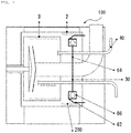
FIG. 1 is an exemplary cross-sectional view of a pressurizing centrifugal dehydrator according to the present invention. -
FIG. 2 is a perspective view of a blocking barrier of the pressurizing centrifugal dehydrator according to the present invention. -
FIG. 3 is a view illustrating a flow of gas and a flow of a dehydration product in the pressurizing centrifugal dehydrator according to the present invention. -
FIG. 4 is an exemplary cross-sectional view of a centrifugal dehydrator according to the related art. - Hereinafter, preferred embodiments of the present invention will be described in detail with reference to the exemplary drawings.
- First, a
centrifugal dehydrator 20 according to the related art will be described with reference toFIG. 4 . - The
centrifugal dehydrator 20 according to the related art includes a dehydrator case 1, aninner basket 3 into which slurry is introduced, anouter basket 2 surrounding theinner basket 2, an outer basket shaft 4, aninner basket shaft 5, a slurry dispersing plate 6, aslurry discharging portion 7, a dehydration and washingwater treatment region 8, a dehydrationproduct treatment region 9, a washingwater supplying portion 10, and aslurry supplying portion 11. - The
centrifugal dehydrator 20 according to the related art may perform removal of moisture from polymer slurry and washing with washing water at the same time in a polymer producing process, and thus has been commonly used in the relevant field. However, there is a limitation in centrifugal force that may be provided by thecentrifugal dehydrator 20, and thus it is difficult to decrease a moisture content of a product to below a predetermined value, which is problematic. - In addition, the
centrifugal dehydrator 20 according to the related art has a structural characteristic in which slurry is supplied to theinner basket 3 through theslurry supplying portion 11, moisture is removed from the slurry, and then a dehydration product obtained by the removal of the moisture is discharged to the outside through theouter basket 2 and the dehydrationproduct treatment region 9. Therefore, it is not possible to maintain airtightness of the basket, and it is thus not possible to perform pressurization by injecting gas into the basket. - On the other hand, with a pressurizing
centrifugal dehydrator 100 according to the present invention, a pressurization centrifugal dehydration technique can be applied while maintaining the above-described components of thecentrifugal dehydrator 20 according to the related art without any change. Therefore, an existing device is reusable. Accordingly, for the pressurizingcentrifugal dehydrator 100 according to the present invention, reference numerals of the components of thecentrifugal dehydrator 20 according to the related art inFig. 4 are used as they are. - The pressurizing
centrifugal dehydrator 100 according to the present invention will be described with reference toFIG. 1 . InFIG. 1 , only reference numerals of main components of the pressurizingcentrifugal dehydrator 100 according to the present invention are illustrated. - The pressurizing
centrifugal dehydrator 100 for removing moisture according to the present invention includes aninner basket 3 into which slurry is introduced, anouter basket 2 surrounding the inner basket, a blockingbarrier 30 disposed in the outer basket, and agas supplying portion 40 for supplying gas into theinner basket 3 orouter basket 2. Adehydration product 200 can be positioned between an outer circumference of theblocking barrier 30 and an inner side of theouter basket 2 to maintain airtightness of theouter basket 2. - According to an embodiment of the present invention, the pressurizing
centrifugal dehydrator 100 can include a slurry supplyingportion 11 for supplying the slurry to the inner basket. - The slurry introduced through the
slurry supplying portion 11 is discharged to theinner basket 3 through a slurrydischarging portion 7, and the slurry discharged through the slurrydischarging portion 7 can be disposed in theinner basket 3 by a slurry dispersing plate 6. - According to an embodiment of the present invention, in the pressurizing
centrifugal dehydrator 100, moisture is removed from the slurry by a centrifugal force of theinner basket 3 and theouter basket 2 caused by rotation of aninner basket shaft 5 and an outer basket shaft 4, and the removed moisture (dehydration) can pass through theinner basket 3 and theouter basket 2 and be discharged through a dehydration and washingwater treatment region 8. - Further, in the pressurizing
centrifugal dehydrator 100, thedehydration product 200 is continuously pushed out along an inner circumferential surface of theinner basket 3 around theinner basket shaft 5 of theinner basket 3 due to reciprocation of theinner basket shaft 5 and the outer basket shaft 4, and the pushed-outdehydration product 200 can be pushed toward between the outer circumference of theblocking barrier 30 and the inner side of theouter basket 2 to move to the dehydrationproduct treatment region 9 and be discharged to the outside. - According to an embodiment of the present invention, the length between the outer circumference of the
blocking barrier 30 and the inner side of theouter basket 2 can be smaller than the height of thedehydration product 200 accumulated along an inner circumferential surface of theouter basket 2 around the outer basket shaft 4 of theouter basket 2. In this case, airtightness between the outer circumference of theblocking barrier 30 and the inner side of theouter basket 2 can be maintained due to thedehydration product 200 accumulated along the inner circumferential surface of theouter basket 2. - According to an embodiment of the present invention, the length of a region adjacent to the outer circumference of the
blocking barrier 30 and the inner side of theouter basket 2 can be larger than the height of thedehydration product 200 accumulated along an inner circumferential surface of theouter basket 2 around the outer basket shaft 4 of theouter basket 2. In this case, it is possible to further increase the airtightness of theouter basket 2. - According to an embodiment of the present invention, in the pressurizing
centrifugal dehydrator 100, gas is supplied to theinner basket 3 orouter basket 2 through thegas supplying portion 40 to pressurize the inside of the basket (inner and outer baskets). In a case of pressurizing the inside of the basket as described above, it is possible to improve dehydration performance of the pressurizingcentrifugal dehydrator 100 due to a pressurization force caused by the gas. - Further, according to an embodiment of the present invention, the
dehydration product 200 can be positioned between theblocking barrier 30 and theouter basket 2 to block the gas in the basket (inner and outer baskets) from being leaked. When the gas is supplied to theinner basket 3 orouter basket 2 in an airtight state, since moisture that is not removable only with the centrifugal force and thus remains in thedehydration product 200 can be additionally removed by the pressurization force of the supplied gas, dehydration performance can be significantly improved, as compared with thecentrifugal dehydrator 20 according to the related art. That is, as two forces, the centrifugal force and the pressurization force, are applied at the same time, the dehydration performance can be improved. AlthoughFIG. 1 illustrates a case of supplying, by thegas supplying portion 40, the gas to theinner basket 3, the gas can be supplied to theinner basket 3, theouter basket 2, or both of theinner basket 3 and theouter basket 2. - Further, according to an embodiment of the present invention, the
dehydration product 200 positioned between the blockingbarrier 30 and theouter basket 2 can be discharged by adehydration product 200 pushed from the inside of the outer basket. Specifically, the discharge of thedehydration product 200 positioned between the outer circumference of the blockingbarrier 30 and the inner side of theouter basket 2 can mean that a process, in which thedehydration product 200 does not remain between the outer circumference of the blockingbarrier 30 and the inner side of theouter basket 2, but is discharged by being pushed by anotherdehydration product 200 pushed from the inside of theouter basket 2, and the anotherdehydration product 200 pushed from the inside of theouter basket 2 is positioned between the blockingbarrier 30 and theouter basket 2, is repeated, and thus thedehydration product 200 always exists between the blockingbarrier 30 and theouter basket 2. - As described above, the process, in which the
dehydration product 200 is discharged by being pushed by anotherdehydration product 200 pushed from the inside of theouter basket 2, and the anotherdehydration product 200 pushed from the inside of theouter basket 2 is positioned between the blockingbarrier 30 and theouter basket 2, is repeated, such that thedehydration product 200 can be continuously discharged by passing between the outer circumference of the blockingbarrier 30 and the inner side of theouter basket 2. - The blocking
barrier 30 will be described in more detail with reference toFIGS. 1 and2 . - According to an embodiment of the present invention, the blocking
barrier 30 includes a blockingbarrier rotating portion 62 that is fixed to theouter basket 2 and rotates together with theouter basket 2, a blockingbarrier fixing portion 64 that is disposed in the blockingbarrier rotating portion 62 and is fixed without rotating, and a rotating-fixingconnection portion 66 disposed between the blockingbarrier rotating portion 62 and the blockingbarrier fixing portion 64. - To minimize friction between the blocking
barrier 30 and thedehydration product 200, the blockingbarrier 30 can be separated into the blockingbarrier rotating portion 62 that rotates, and the blockingbarrier fixing portion 64 that is fixed without rotating. - The blocking
barrier rotating portion 62 rotates together with theouter basket 2, thereby minimizing friction caused by rotation of thedehydration product 200. - The blocking
barrier fixing portion 64 can be fixed to theslurry supplying portion 11 or can be fixed to another pipe to prevent the blockingbarrier 30 from being pushed by the dischargeddehydration product 200 and escaping to the outside. A fixing target of the blockingbarrier fixing portion 64 is not limited. - The rotating-fixing
connection portion 66 connects the blockingbarrier rotating portion 62 and the blockingbarrier fixing portion 64, and parts such as a bearing and a roller can be used. However, the rotating-fixingconnection portion 66 is not limited thereto. As such, as the rotating-fixingconnection portion 66 is provided between the blockingbarrier rotating portion 62 and the blockingbarrier fixing portion 64, the blockingbarrier rotating portion 62 rotates together with theouter basket 2, and the rotation is transferred to the rotating-fixingconnection portion 66. However, the blockingbarrier fixing portion 64 can be fixed. - As illustrated in
FIG. 2 , aninclined portion 68 can be formed in the blockingbarrier rotating portion 62. Theinclined portion 68 enables smoother introduction of thedehydration product 200 between the blockingbarrier rotating portion 62 and theouter basket 2, such that airtightness between the blockingbarrier rotating portion 62 and theouter basket 2 is improved. That is, theinclined portion 68 serves as a guide portion. Thedehydration product 200 can be continuously supplied to a dehydrationproduct discharging portion 52 by a force in an axial direction and then discharged. - As illustrated in
FIG. 1 , the blockingbarrier rotating portion 62 can protrude from theouter basket 2 in an axial direction of the outer basket 2 (inFIG. 1 , the blockingbarrier rotating portion 62 protrudes from theouter basket 2 to the right side). In this case, it is possible to more effectively maintain airtightness of theouter basket 2 and guide thedehydration product 200 moving between the outer circumference of the blockingbarrier 30 and the inner side of theouter basket 2 to be discharged to the outside through the dehydrationproduct discharging portion 52. - Referring to
FIG. 2 , in the blockingbarrier 30, a slurry supplying portion hole 34 through which theslurry supplying portion 11 penetrates, a washing water supplying portion hole 36 through which a washingwater supplying portion 10 penetrates, and a gas supplying portion hole 38 which communicates with thegas supplying portion 40 can be formed. - The gas supplying portion hole 38, the slurry supplying portion hole 34, and the washing water supplying portion hole 36 can be sequentially illustrated from top to bottom in
FIG. 2 , and a sequence and arrangement thereof can vary. Further, in a case where an additional pipe is provided in thecentrifugal dehydrator 20 according to the related art, a hole through which the corresponding pipe can penetrate can be additionally formed in the blockingbarrier 30. Accordingly, the pressurization centrifugal dehydration technique can be applied while maintaining the components of thecentrifugal dehydrator 20 according to the related art without any change. Therefore, an existing device is reusable. -
FIG. 3 illustrates a flow of gas to amoisture discharging portion 50, and a flow of thedehydration product 200 to the dehydrationproduct discharging portion 52. As described above, thedehydration product 200 is concentrated in between the outer circumference (specifically, an outer circumference of the blocking barrier rotating portion 62) of the blockingbarrier 30, and the inner side of theouter basket 2, such that it is possible to maintain airtightness of the basket. The gas supplied by thegas supplying portion 40 pressurizes the dehydration product to additionally remove moisture remaining in thedehydration product 200 in a state where the airtightness of the basket is maintained by the blockingbarrier 30 and thedehydration product 200. - The spirit of the present invention has been illustratively described hereinabove. It will be appreciated by those skilled in the art that various modifications and alterations can be made without departing from the essential characteristics of the present invention. Accordingly, exemplary embodiments disclosed in the present invention are not to limit the spirit of the present invention, but are to describe the spirit of the present invention. The scope of the present invention is not limited to these exemplary embodiments. The scope of the present invention should be interpreted by the following claims, and it should be interpreted that all the spirits equivalent to the following claims fall within the scope of the present invention.
Claims (9)
- A pressurizing centrifugal dehydrator for removing moisture, the pressurizing centrifugal dehydrator comprising:an inner basket into which slurry is introduced;an outer basket surrounding the inner basket;a blocking barrier disposed in the outer basket; anda gas supplying portion for supplying gas into the inner basket or the outer basket,wherein a dehydration product is positioned between an outer circumference of the blocking barrier and an inner side of the outer basket to maintain airtightness of the outer basket.
- The pressurizing centrifugal dehydrator of claim 1, wherein a gas supplying portion hole, through which the gas supplying portion penetrates, is formed in the blocking barrier.
- The pressurizing centrifugal dehydrator of claim 1, wherein a slurry supplying portion hole, through which a slurry supplying portion for supplying the slurry to the inner basket penetrates, is formed in the blocking barrier.
- The pressurizing centrifugal dehydrator of claim 1, wherein a washing water supplying portion hole, through which a washing water supplying portion for supplying washing water to the inner basket penetrates, is formed in the blocking barrier.
- The pressurizing centrifugal dehydrator of claim 1, wherein the dehydration product positioned between the outer circumference of the blocking barrier and the inner side of the outer basket is discharged due to a dehydration product pushed from the inside of the outer basket.
- The pressurizing centrifugal dehydrator of claim 1, wherein the dehydration product is continuously discharged by passing between the outer circumference of the blocking barrier and the inner side of the outer basket.
- The pressurizing centrifugal dehydrator of claim 1, wherein the blocking barrier includes:a blocking barrier rotating portion that is fixed to the outer basket and rotates together with the outer basket;a blocking barrier fixing portion that is disposed inside the blocking barrier rotating portion and is fixed; anda rotating-fixing connection portion disposed between the blocking barrier rotating portion and the blocking barrier fixing portion.
- The pressurizing centrifugal dehydrator of claim 7, wherein the rotating-fixing connection portion fixes the blocking barrier fixing portion while allowing rotation of the blocking barrier rotating portion.
- The pressurizing centrifugal dehydrator of claim 7, wherein an inclined portion is formed in the blocking barrier rotating portion.
Applications Claiming Priority (2)
| Application Number | Priority Date | Filing Date | Title |
|---|---|---|---|
| KR1020190147408A KR102504659B1 (en) | 2019-11-18 | 2019-11-18 | Pressurizing centrifugal dehydrator |
| PCT/KR2020/009206 WO2021101011A1 (en) | 2019-11-18 | 2020-07-13 | Pressurizing centrifugal dehydrator |
Publications (3)
| Publication Number | Publication Date |
|---|---|
| EP3848126A1 true EP3848126A1 (en) | 2021-07-14 |
| EP3848126A4 EP3848126A4 (en) | 2021-10-13 |
| EP3848126B1 EP3848126B1 (en) | 2023-08-30 |
Family
ID=74946926
Family Applications (1)
| Application Number | Title | Priority Date | Filing Date |
|---|---|---|---|
| EP20848781.9A Active EP3848126B1 (en) | 2019-11-18 | 2020-07-13 | Pressurizing centrifugal dehydrator |
Country Status (5)
| Country | Link |
|---|---|
| US (1) | US11944987B2 (en) |
| EP (1) | EP3848126B1 (en) |
| KR (1) | KR102504659B1 (en) |
| CN (1) | CN113227692B (en) |
| WO (1) | WO2021101011A1 (en) |
Families Citing this family (2)
| Publication number | Priority date | Publication date | Assignee | Title |
|---|---|---|---|---|
| JP2021506576A (en) * | 2017-12-19 | 2021-02-22 | ゼロス リミテッド | Filter for processing equipment |
| KR102504657B1 (en) * | 2019-11-18 | 2023-02-27 | 주식회사 엘지화학 | Pressurizing centrifugal dehydrator |
Family Cites Families (40)
| Publication number | Priority date | Publication date | Assignee | Title |
|---|---|---|---|---|
| CA894943A (en) * | 1972-03-07 | Ruegg Ernst | Pusher centrifuge with two or more drums | |
| NL184631B (en) * | 1953-02-10 | Lubrizol Corp | CONVERSION PRODUCT OF AN ALKYL OR ALKENYL GROUP SUBSTITUED AMINSTIC ACID OR ANHYDRIDE THEREOF WITH A HYDROXYALKYLAMINE, AND FUNCTIONAL FLUIDS DISPERSED IN WATER, WHICH CONTAINS THE CONVERSION PRODUCT. | |
| US2732073A (en) * | 1953-11-23 | 1956-01-24 | Roegg | |
| DE1482709A1 (en) * | 1964-07-04 | 1969-12-18 | Ceskoslovenska Akademie Ved | Continuously working centrifuge |
| JPS55127115A (en) * | 1979-02-02 | 1980-10-01 | Misuzu Kogyo:Kk | Water separator |
| CH655786A5 (en) * | 1981-07-03 | 1986-05-15 | Escher Wyss Ag | Heat exchanger and use thereof |
| DE3817126A1 (en) * | 1988-05-19 | 1989-11-30 | Krauss Maffei Ag | FILTER CENTRIFUGE TO SEPARATE SUSPENSIONS |
| CH679016A5 (en) * | 1989-09-29 | 1991-12-13 | Escher Wyss Ag | |
| JPH0751165Y2 (en) * | 1991-12-04 | 1995-11-22 | 長縄工業株式会社 | Sludge dehydrator by air press and centrifugal separation |
| KR0145510B1 (en) * | 1994-11-28 | 1998-07-15 | 김영대 | Apparatus for washing screw filter press for dlwatering |
| JP2000233106A (en) * | 1999-02-16 | 2000-08-29 | Mitsubishi Kakoki Kaisha Ltd | Apparatus for removing base layer of basket type centrifugal filtration apparatus and method for removing base layer |
| US6440316B1 (en) * | 2000-03-21 | 2002-08-27 | Virginia Tech Intellectual Properties, Inc. | Methods of improving centrifugal filtration |
| DE10245013A1 (en) * | 2002-09-20 | 2004-04-01 | Heinkel Aktiengesellschaft | Filter centrifuge, used in solid/liquid separation processes, comprises housing, outer drum connected to housing, filter unit fixed in drum, and drive shaft fixed to outer drum and filter unit |
| JP3683568B2 (en) * | 2003-01-28 | 2005-08-17 | 月島機械株式会社 | Centrifuge method and centrifuge |
| ATE397496T1 (en) * | 2003-04-16 | 2008-06-15 | Ferrum Ag | PUSH CENTRIFUGE WITH ROTATING FUNNEL FOR ACCELERATION OF THE MIXTURE |
| KR20060089881A (en) * | 2005-02-03 | 2006-08-10 | 주식회사 루펜비아이에프 | Food waste dehydration device |
| ES2619155T3 (en) * | 2005-11-18 | 2017-06-23 | Ferrum Ag | Centrifuge cartridge |
| KR100755863B1 (en) * | 2006-06-12 | 2007-09-05 | 엘지전자 주식회사 | Dryer and its control method |
| DE102006054766A1 (en) * | 2006-11-14 | 2008-05-15 | Fima Maschinenbau Gmbh | Centrifuge dryer with improved NIR spectroscopy |
| CN101380611A (en) * | 2008-08-28 | 2009-03-11 | 四川大学 | Filtration and dehydration-drying integrated centrifuge |
| JP4848029B2 (en) | 2009-09-07 | 2011-12-28 | 株式会社松本機械製作所 | centrifuge |
| DK2582440T3 (en) * | 2010-06-15 | 2019-07-22 | Centrisys Corp | CENTRIFUGAL LIQUID SEPARATION MACHINE USING PRESSURE AIR TO PROMOTE SOLID SUPPLY |
| CN102564073A (en) * | 2011-01-03 | 2012-07-11 | 肖功宽 | Bean curd dehydration air pressure method by use of double-tub washing machine dehydrator |
| JP5191565B2 (en) * | 2011-02-25 | 2013-05-08 | 寿工業株式会社 | Centrifugal dehydration method and centrifugal dehydration apparatus |
| DE102011055513A1 (en) * | 2011-11-18 | 2013-05-23 | Andritz Kmpt Gmbh | Push compressor has rotary filter drum with longitudinal axis, filter drum inner peripheral surface and drum body, where push floor is arranged in filter drum, and push floor and drum body are movable axially in back and forth direction |
| CN104707740A (en) * | 2013-12-17 | 2015-06-17 | 北方华锦化学工业集团有限公司 | Washing method and device matched with continuous automatic material pushing type centrifugal dewaterer |
| CN203737427U (en) * | 2013-12-20 | 2014-07-30 | 重庆江北机械有限责任公司 | Pressurizing piston material-pushing centrifugal machine |
| JP2015144989A (en) | 2014-02-03 | 2015-08-13 | 株式会社松本機械製作所 | centrifuge |
| CN203862419U (en) * | 2014-05-28 | 2014-10-08 | 中国矿业大学 | Centrifugal filtration dehydration device for fine-grain materials |
| CN103977915A (en) * | 2014-05-28 | 2014-08-13 | 中国矿业大学 | Fine-grain material centrifugal filtering and dewatering device |
| CN104984836A (en) * | 2015-06-16 | 2015-10-21 | 镇江港和新型建材有限公司 | Centrifugal machine with double-layer rotary drum structure |
| JP6578254B2 (en) * | 2016-07-05 | 2019-09-18 | 月島機械株式会社 | Centrifuge and centrifuge method |
| KR101738388B1 (en) * | 2016-11-15 | 2017-05-29 | (주)동일캔바스엔지니어링 | Centrifugal dehydrator with air nozzle |
| CN108796994B (en) * | 2017-04-28 | 2022-08-16 | 青岛海尔洗衣机有限公司 | Dewatering structure of washing machine |
| CN107262297B (en) * | 2017-06-12 | 2019-07-26 | 沈阳化工大学 | A blast high-efficiency filter centrifuge |
| CN207294565U (en) * | 2017-09-08 | 2018-05-01 | 武汉卓品环保科技有限公司 | Quill shaft sludge scum silica frost centrifugal dehydrator |
| CN108413734A (en) * | 2018-04-07 | 2018-08-17 | 张传开 | A kind of middle medical drugs material dryer |
| CN109821669A (en) * | 2019-03-20 | 2019-05-31 | 苏州星亿机械有限公司 | A water throwing device for a casing |
| CN110388465B (en) * | 2019-07-26 | 2020-05-12 | 浙江轻机实业有限公司 | Reverse leakage sealing method for two-stage material-pushing centrifugal machine |
| CN110394241A (en) * | 2019-08-30 | 2019-11-01 | 张家港市蓝鸟机械有限公司 | Flat hanging bag conveyer centrifugal |
-
2019
- 2019-11-18 KR KR1020190147408A patent/KR102504659B1/en active Active
-
2020
- 2020-07-13 WO PCT/KR2020/009206 patent/WO2021101011A1/en not_active Ceased
- 2020-07-13 US US17/269,203 patent/US11944987B2/en active Active
- 2020-07-13 CN CN202080004625.9A patent/CN113227692B/en active Active
- 2020-07-13 EP EP20848781.9A patent/EP3848126B1/en active Active
Also Published As
| Publication number | Publication date |
|---|---|
| CN113227692B (en) | 2023-03-17 |
| KR102504659B1 (en) | 2023-02-27 |
| US11944987B2 (en) | 2024-04-02 |
| KR20210059956A (en) | 2021-05-26 |
| CN113227692A (en) | 2021-08-06 |
| EP3848126A4 (en) | 2021-10-13 |
| WO2021101011A1 (en) | 2021-05-27 |
| EP3848126B1 (en) | 2023-08-30 |
| US20220016646A1 (en) | 2022-01-20 |
Similar Documents
| Publication | Publication Date | Title |
|---|---|---|
| US11833458B2 (en) | Pressurizing centrifugal dehydrator | |
| US11944987B2 (en) | Pressurizing centrifugal dehydrator | |
| US20160363123A1 (en) | Hybrid radial axial cutter | |
| CN106671466B (en) | Screw extruder for straw dehydration | |
| US2758783A (en) | Centrifugal countercurrent exchange device | |
| US2098024A (en) | Vacuum drier with centrifugal dust separator | |
| CN107715988A (en) | A kind of economic benefits and social benefits antisitic defect roller presses mill apparatus | |
| KR100900723B1 (en) | Slurry centrifugal dehydrator | |
| CN109862707A (en) | A kind of pre-treating technology of circuit board printing | |
| ATE421383T1 (en) | METHOD FOR OPERATION OF A CENTRIFUGE | |
| RU2013119958A (en) | DEVICE FOR MANUFACTURE OF PURPOSE LOGS FROM LOGS AND METHOD FOR PRODUCING WOODEN COMPOSITE MATERIAL USING MACRO FIBERS | |
| FI94364C (en) | Apparatus for the processing of malt goods | |
| SE8403023L (en) | SET AND DEVICE FOR REMOVING THE WATER FROM A LIQUID OR PASTERY MIXTURE | |
| CN111162026A (en) | An etched surface anti-oxidation treatment device | |
| CN105133407B (en) | Integrated system for washing steam explosion product and separating solid, liquid and gas of steam explosion product | |
| EP3228444B1 (en) | Pressing unit for removing liquids | |
| US4741184A (en) | Laundry press | |
| CN209138890U (en) | A kind of filter cake removing horizontal type scraper centrifuger | |
| US5013460A (en) | Centrifugal washer for paper pulp with means to feed pulp as a thin sheet | |
| RU2722757C1 (en) | Veneer processing method | |
| ITMI20000156A1 (en) | PROCEDURE AND EQUIPMENT FOR THE EXTRACTION OF THE LIQUID COMPONENT OF A COMPOUND PRODUCT WITH ENERGY RECOVERY OF THE LI COMPONENT | |
| CN107983466A (en) | A kind of multistage antisitic defect roller reducing mechanism | |
| CN204602429U (en) | A kind of anti-explosion horizontal centrifuge | |
| RU2588517C2 (en) | Method for formation of external thread on end of fibre glass pipe and device therefor | |
| CN110068220A (en) | The improvement of wood technology technology |
Legal Events
| Date | Code | Title | Description |
|---|---|---|---|
| STAA | Information on the status of an ep patent application or granted ep patent |
Free format text: STATUS: UNKNOWN |
|
| STAA | Information on the status of an ep patent application or granted ep patent |
Free format text: STATUS: THE INTERNATIONAL PUBLICATION HAS BEEN MADE |
|
| PUAI | Public reference made under article 153(3) epc to a published international application that has entered the european phase |
Free format text: ORIGINAL CODE: 0009012 |
|
| STAA | Information on the status of an ep patent application or granted ep patent |
Free format text: STATUS: REQUEST FOR EXAMINATION WAS MADE |
|
| 17P | Request for examination filed |
Effective date: 20210209 |
|
| AK | Designated contracting states |
Kind code of ref document: A1 Designated state(s): AL AT BE BG CH CY CZ DE DK EE ES FI FR GB GR HR HU IE IS IT LI LT LU LV MC MK MT NL NO PL PT RO RS SE SI SK SM TR |
|
| REG | Reference to a national code |
Ref country code: DE Free format text: PREVIOUS MAIN CLASS: B04B0015000000 Ref country code: DE Ref legal event code: R079 Ref document number: 602020016948 Country of ref document: DE Free format text: PREVIOUS MAIN CLASS: B04B0015000000 Ipc: B04B0015120000 |
|
| A4 | Supplementary search report drawn up and despatched |
Effective date: 20210914 |
|
| RIC1 | Information provided on ipc code assigned before grant |
Ipc: F26B 5/08 20060101ALI20210908BHEP Ipc: B04B 7/12 20060101ALI20210908BHEP Ipc: B04B 3/00 20060101ALI20210908BHEP Ipc: B04B 3/02 20060101ALI20210908BHEP Ipc: B04B 15/12 20060101AFI20210908BHEP |
|
| DAV | Request for validation of the european patent (deleted) | ||
| DAX | Request for extension of the european patent (deleted) | ||
| GRAP | Despatch of communication of intention to grant a patent |
Free format text: ORIGINAL CODE: EPIDOSNIGR1 |
|
| STAA | Information on the status of an ep patent application or granted ep patent |
Free format text: STATUS: GRANT OF PATENT IS INTENDED |
|
| RIC1 | Information provided on ipc code assigned before grant |
Ipc: F26B 3/06 20060101ALI20230224BHEP Ipc: F26B 5/08 20060101ALI20230224BHEP Ipc: B04B 7/12 20060101ALI20230224BHEP Ipc: B04B 3/00 20060101ALI20230224BHEP Ipc: B04B 3/02 20060101ALI20230224BHEP Ipc: B04B 15/12 20060101AFI20230224BHEP |
|
| INTG | Intention to grant announced |
Effective date: 20230327 |
|
| GRAS | Grant fee paid |
Free format text: ORIGINAL CODE: EPIDOSNIGR3 |
|
| GRAA | (expected) grant |
Free format text: ORIGINAL CODE: 0009210 |
|
| STAA | Information on the status of an ep patent application or granted ep patent |
Free format text: STATUS: THE PATENT HAS BEEN GRANTED |
|
| AK | Designated contracting states |
Kind code of ref document: B1 Designated state(s): AL AT BE BG CH CY CZ DE DK EE ES FI FR GB GR HR HU IE IS IT LI LT LU LV MC MK MT NL NO PL PT RO RS SE SI SK SM TR |
|
| REG | Reference to a national code |
Ref country code: GB Ref legal event code: FG4D |
|
| REG | Reference to a national code |
Ref country code: CH Ref legal event code: EP |
|
| REG | Reference to a national code |
Ref country code: DE Ref legal event code: R096 Ref document number: 602020016948 Country of ref document: DE |
|
| REG | Reference to a national code |
Ref country code: IE Ref legal event code: FG4D |
|
| REG | Reference to a national code |
Ref country code: LT Ref legal event code: MG9D |
|
| REG | Reference to a national code |
Ref country code: NL Ref legal event code: MP Effective date: 20230830 |
|
| REG | Reference to a national code |
Ref country code: AT Ref legal event code: MK05 Ref document number: 1604737 Country of ref document: AT Kind code of ref document: T Effective date: 20230830 |
|
| PG25 | Lapsed in a contracting state [announced via postgrant information from national office to epo] |
Ref country code: GR Free format text: LAPSE BECAUSE OF FAILURE TO SUBMIT A TRANSLATION OF THE DESCRIPTION OR TO PAY THE FEE WITHIN THE PRESCRIBED TIME-LIMIT Effective date: 20231201 |
|
| PG25 | Lapsed in a contracting state [announced via postgrant information from national office to epo] |
Ref country code: IS Free format text: LAPSE BECAUSE OF FAILURE TO SUBMIT A TRANSLATION OF THE DESCRIPTION OR TO PAY THE FEE WITHIN THE PRESCRIBED TIME-LIMIT Effective date: 20231230 |
|
| PG25 | Lapsed in a contracting state [announced via postgrant information from national office to epo] |
Ref country code: SE Free format text: LAPSE BECAUSE OF FAILURE TO SUBMIT A TRANSLATION OF THE DESCRIPTION OR TO PAY THE FEE WITHIN THE PRESCRIBED TIME-LIMIT Effective date: 20230830 Ref country code: RS Free format text: LAPSE BECAUSE OF FAILURE TO SUBMIT A TRANSLATION OF THE DESCRIPTION OR TO PAY THE FEE WITHIN THE PRESCRIBED TIME-LIMIT Effective date: 20230830 Ref country code: NO Free format text: LAPSE BECAUSE OF FAILURE TO SUBMIT A TRANSLATION OF THE DESCRIPTION OR TO PAY THE FEE WITHIN THE PRESCRIBED TIME-LIMIT Effective date: 20231130 Ref country code: LV Free format text: LAPSE BECAUSE OF FAILURE TO SUBMIT A TRANSLATION OF THE DESCRIPTION OR TO PAY THE FEE WITHIN THE PRESCRIBED TIME-LIMIT Effective date: 20230830 Ref country code: LT Free format text: LAPSE BECAUSE OF FAILURE TO SUBMIT A TRANSLATION OF THE DESCRIPTION OR TO PAY THE FEE WITHIN THE PRESCRIBED TIME-LIMIT Effective date: 20230830 Ref country code: IS Free format text: LAPSE BECAUSE OF FAILURE TO SUBMIT A TRANSLATION OF THE DESCRIPTION OR TO PAY THE FEE WITHIN THE PRESCRIBED TIME-LIMIT Effective date: 20231230 Ref country code: HR Free format text: LAPSE BECAUSE OF FAILURE TO SUBMIT A TRANSLATION OF THE DESCRIPTION OR TO PAY THE FEE WITHIN THE PRESCRIBED TIME-LIMIT Effective date: 20230830 Ref country code: GR Free format text: LAPSE BECAUSE OF FAILURE TO SUBMIT A TRANSLATION OF THE DESCRIPTION OR TO PAY THE FEE WITHIN THE PRESCRIBED TIME-LIMIT Effective date: 20231201 Ref country code: FI Free format text: LAPSE BECAUSE OF FAILURE TO SUBMIT A TRANSLATION OF THE DESCRIPTION OR TO PAY THE FEE WITHIN THE PRESCRIBED TIME-LIMIT Effective date: 20230830 Ref country code: AT Free format text: LAPSE BECAUSE OF FAILURE TO SUBMIT A TRANSLATION OF THE DESCRIPTION OR TO PAY THE FEE WITHIN THE PRESCRIBED TIME-LIMIT Effective date: 20230830 |
|
| PG25 | Lapsed in a contracting state [announced via postgrant information from national office to epo] |
Ref country code: PL Free format text: LAPSE BECAUSE OF FAILURE TO SUBMIT A TRANSLATION OF THE DESCRIPTION OR TO PAY THE FEE WITHIN THE PRESCRIBED TIME-LIMIT Effective date: 20230830 Ref country code: NL Free format text: LAPSE BECAUSE OF FAILURE TO SUBMIT A TRANSLATION OF THE DESCRIPTION OR TO PAY THE FEE WITHIN THE PRESCRIBED TIME-LIMIT Effective date: 20230830 |
|
| PG25 | Lapsed in a contracting state [announced via postgrant information from national office to epo] |
Ref country code: ES Free format text: LAPSE BECAUSE OF FAILURE TO SUBMIT A TRANSLATION OF THE DESCRIPTION OR TO PAY THE FEE WITHIN THE PRESCRIBED TIME-LIMIT Effective date: 20230830 |
|
| PG25 | Lapsed in a contracting state [announced via postgrant information from national office to epo] |
Ref country code: SM Free format text: LAPSE BECAUSE OF FAILURE TO SUBMIT A TRANSLATION OF THE DESCRIPTION OR TO PAY THE FEE WITHIN THE PRESCRIBED TIME-LIMIT Effective date: 20230830 Ref country code: RO Free format text: LAPSE BECAUSE OF FAILURE TO SUBMIT A TRANSLATION OF THE DESCRIPTION OR TO PAY THE FEE WITHIN THE PRESCRIBED TIME-LIMIT Effective date: 20230830 Ref country code: ES Free format text: LAPSE BECAUSE OF FAILURE TO SUBMIT A TRANSLATION OF THE DESCRIPTION OR TO PAY THE FEE WITHIN THE PRESCRIBED TIME-LIMIT Effective date: 20230830 Ref country code: EE Free format text: LAPSE BECAUSE OF FAILURE TO SUBMIT A TRANSLATION OF THE DESCRIPTION OR TO PAY THE FEE WITHIN THE PRESCRIBED TIME-LIMIT Effective date: 20230830 Ref country code: DK Free format text: LAPSE BECAUSE OF FAILURE TO SUBMIT A TRANSLATION OF THE DESCRIPTION OR TO PAY THE FEE WITHIN THE PRESCRIBED TIME-LIMIT Effective date: 20230830 Ref country code: CZ Free format text: LAPSE BECAUSE OF FAILURE TO SUBMIT A TRANSLATION OF THE DESCRIPTION OR TO PAY THE FEE WITHIN THE PRESCRIBED TIME-LIMIT Effective date: 20230830 Ref country code: SK Free format text: LAPSE BECAUSE OF FAILURE TO SUBMIT A TRANSLATION OF THE DESCRIPTION OR TO PAY THE FEE WITHIN THE PRESCRIBED TIME-LIMIT Effective date: 20230830 Ref country code: PT Free format text: LAPSE BECAUSE OF FAILURE TO SUBMIT A TRANSLATION OF THE DESCRIPTION OR TO PAY THE FEE WITHIN THE PRESCRIBED TIME-LIMIT Effective date: 20240102 |
|
| PG25 | Lapsed in a contracting state [announced via postgrant information from national office to epo] |
Ref country code: IT Free format text: LAPSE BECAUSE OF FAILURE TO SUBMIT A TRANSLATION OF THE DESCRIPTION OR TO PAY THE FEE WITHIN THE PRESCRIBED TIME-LIMIT Effective date: 20230830 |
|
| REG | Reference to a national code |
Ref country code: DE Ref legal event code: R097 Ref document number: 602020016948 Country of ref document: DE |
|
| PLBE | No opposition filed within time limit |
Free format text: ORIGINAL CODE: 0009261 |
|
| STAA | Information on the status of an ep patent application or granted ep patent |
Free format text: STATUS: NO OPPOSITION FILED WITHIN TIME LIMIT |
|
| PG25 | Lapsed in a contracting state [announced via postgrant information from national office to epo] |
Ref country code: SI Free format text: LAPSE BECAUSE OF FAILURE TO SUBMIT A TRANSLATION OF THE DESCRIPTION OR TO PAY THE FEE WITHIN THE PRESCRIBED TIME-LIMIT Effective date: 20230830 |
|
| 26N | No opposition filed |
Effective date: 20240603 |
|
| PG25 | Lapsed in a contracting state [announced via postgrant information from national office to epo] |
Ref country code: BG Free format text: LAPSE BECAUSE OF FAILURE TO SUBMIT A TRANSLATION OF THE DESCRIPTION OR TO PAY THE FEE WITHIN THE PRESCRIBED TIME-LIMIT Effective date: 20230830 |
|
| PG25 | Lapsed in a contracting state [announced via postgrant information from national office to epo] |
Ref country code: BG Free format text: LAPSE BECAUSE OF FAILURE TO SUBMIT A TRANSLATION OF THE DESCRIPTION OR TO PAY THE FEE WITHIN THE PRESCRIBED TIME-LIMIT Effective date: 20230830 |
|
| PG25 | Lapsed in a contracting state [announced via postgrant information from national office to epo] |
Ref country code: MC Free format text: LAPSE BECAUSE OF FAILURE TO SUBMIT A TRANSLATION OF THE DESCRIPTION OR TO PAY THE FEE WITHIN THE PRESCRIBED TIME-LIMIT Effective date: 20230830 |
|
| REG | Reference to a national code |
Ref country code: CH Ref legal event code: PL |
|
| PG25 | Lapsed in a contracting state [announced via postgrant information from national office to epo] |
Ref country code: LU Free format text: LAPSE BECAUSE OF NON-PAYMENT OF DUE FEES Effective date: 20240713 |
|
| PG25 | Lapsed in a contracting state [announced via postgrant information from national office to epo] |
Ref country code: LU Free format text: LAPSE BECAUSE OF NON-PAYMENT OF DUE FEES Effective date: 20240713 |
|
| PG25 | Lapsed in a contracting state [announced via postgrant information from national office to epo] |
Ref country code: BE Free format text: LAPSE BECAUSE OF NON-PAYMENT OF DUE FEES Effective date: 20240731 Ref country code: CH Free format text: LAPSE BECAUSE OF NON-PAYMENT OF DUE FEES Effective date: 20240731 |
|
| REG | Reference to a national code |
Ref country code: BE Ref legal event code: MM Effective date: 20240731 |
|
| PGFP | Annual fee paid to national office [announced via postgrant information from national office to epo] |
Ref country code: GB Payment date: 20250624 Year of fee payment: 6 |
|
| PGFP | Annual fee paid to national office [announced via postgrant information from national office to epo] |
Ref country code: FR Payment date: 20250624 Year of fee payment: 6 |
|
| PG25 | Lapsed in a contracting state [announced via postgrant information from national office to epo] |
Ref country code: IE Free format text: LAPSE BECAUSE OF NON-PAYMENT OF DUE FEES Effective date: 20240713 |
|
| PGFP | Annual fee paid to national office [announced via postgrant information from national office to epo] |
Ref country code: DE Payment date: 20250624 Year of fee payment: 6 |
|
| PG25 | Lapsed in a contracting state [announced via postgrant information from national office to epo] |
Ref country code: CY Free format text: LAPSE BECAUSE OF FAILURE TO SUBMIT A TRANSLATION OF THE DESCRIPTION OR TO PAY THE FEE WITHIN THE PRESCRIBED TIME-LIMIT; INVALID AB INITIO Effective date: 20200713 |
|
| PG25 | Lapsed in a contracting state [announced via postgrant information from national office to epo] |
Ref country code: HU Free format text: LAPSE BECAUSE OF FAILURE TO SUBMIT A TRANSLATION OF THE DESCRIPTION OR TO PAY THE FEE WITHIN THE PRESCRIBED TIME-LIMIT; INVALID AB INITIO Effective date: 20200713 |