EP3848097B1 - Übungsvorrichtung - Google Patents
Übungsvorrichtung Download PDFInfo
- Publication number
- EP3848097B1 EP3848097B1 EP20150610.2A EP20150610A EP3848097B1 EP 3848097 B1 EP3848097 B1 EP 3848097B1 EP 20150610 A EP20150610 A EP 20150610A EP 3848097 B1 EP3848097 B1 EP 3848097B1
- Authority
- EP
- European Patent Office
- Prior art keywords
- magnetoresistive
- rings
- magnetic
- disposed
- magnetic portions
- Prior art date
- Legal status (The legal status is an assumption and is not a legal conclusion. Google has not performed a legal analysis and makes no representation as to the accuracy of the status listed.)
- Active
Links
Images


Classifications
-
- A—HUMAN NECESSITIES
- A63—SPORTS; GAMES; AMUSEMENTS
- A63B—APPARATUS FOR PHYSICAL TRAINING, GYMNASTICS, SWIMMING, CLIMBING, OR FENCING; BALL GAMES; TRAINING EQUIPMENT
- A63B22/00—Exercising apparatus specially adapted for conditioning the cardio-vascular system, for training agility or co-ordination of movements
- A63B22/06—Exercising apparatus specially adapted for conditioning the cardio-vascular system, for training agility or co-ordination of movements with support elements performing a rotating cycling movement, i.e. a closed path movement
- A63B22/0605—Exercising apparatus specially adapted for conditioning the cardio-vascular system, for training agility or co-ordination of movements with support elements performing a rotating cycling movement, i.e. a closed path movement performing a circular movement, e.g. ergometers
-
- A—HUMAN NECESSITIES
- A63—SPORTS; GAMES; AMUSEMENTS
- A63B—APPARATUS FOR PHYSICAL TRAINING, GYMNASTICS, SWIMMING, CLIMBING, OR FENCING; BALL GAMES; TRAINING EQUIPMENT
- A63B21/00—Exercising apparatus for developing or strengthening the muscles or joints of the body by working against a counterforce, with or without measuring devices
- A63B21/00058—Mechanical means for varying the resistance
- A63B21/00069—Setting or adjusting the resistance level; Compensating for a preload prior to use, e.g. changing length of resistance or adjusting a valve
-
- A—HUMAN NECESSITIES
- A63—SPORTS; GAMES; AMUSEMENTS
- A63B—APPARATUS FOR PHYSICAL TRAINING, GYMNASTICS, SWIMMING, CLIMBING, OR FENCING; BALL GAMES; TRAINING EQUIPMENT
- A63B21/00—Exercising apparatus for developing or strengthening the muscles or joints of the body by working against a counterforce, with or without measuring devices
- A63B21/005—Exercising apparatus for developing or strengthening the muscles or joints of the body by working against a counterforce, with or without measuring devices using electromagnetic or electric force-resisters
- A63B21/0051—Exercising apparatus for developing or strengthening the muscles or joints of the body by working against a counterforce, with or without measuring devices using electromagnetic or electric force-resisters using eddy currents induced in moved elements, e.g. by permanent magnets
-
- A—HUMAN NECESSITIES
- A63—SPORTS; GAMES; AMUSEMENTS
- A63B—APPARATUS FOR PHYSICAL TRAINING, GYMNASTICS, SWIMMING, CLIMBING, OR FENCING; BALL GAMES; TRAINING EQUIPMENT
- A63B21/00—Exercising apparatus for developing or strengthening the muscles or joints of the body by working against a counterforce, with or without measuring devices
- A63B21/008—Exercising apparatus for developing or strengthening the muscles or joints of the body by working against a counterforce, with or without measuring devices using hydraulic or pneumatic force-resisters
- A63B21/0085—Exercising apparatus for developing or strengthening the muscles or joints of the body by working against a counterforce, with or without measuring devices using hydraulic or pneumatic force-resisters using pneumatic force-resisters
- A63B21/0088—Exercising apparatus for developing or strengthening the muscles or joints of the body by working against a counterforce, with or without measuring devices using hydraulic or pneumatic force-resisters using pneumatic force-resisters by moving the surrounding air
Definitions
- the present invention relates to an exercise device.
- a conventional fan-type exercise bike includes a main body, a fan wheel disposed on the main body and a magnetic resistance unit which is configured to provide different resistance according to using requirements.
- the conventional fan-type exercise bike has insufficient resistance, which cannot meet using requirements; the magnetic resistance unit has a complicated structure, which is inconvenient to manufacture and maintain.
- US-A-2019/255376 discloses an example of an exercise device.
- the present invention is, therefore, arisen to obviate or at least mitigate the above-mentioned disadvantages.
- the main object of the present invention is to provide an exercise device which provides sufficient operating resistance and has a simple magnetic resistance adjusting structure.
- an exercise device including: a main body, two fan wheels and a magnetic resistance assembly.
- the main body includes an axle disposed thereon.
- the two fan wheels are connected to the axle and rotatable relative to the main body.
- the magnetic resistance assembly includes two magnetoresistive rings disposed respectively on the two fan wheels and around the axle, a magnetic unit and a controlling unit.
- the magnetic unit includes two magnetic portions respectively corresponding to the two magnetoresistive rings.
- the controlling unit includes a lever rotatably disposed on the main body at a pivot point, and the magnetic unit and an operating portion are disposed on the lever and located by two opposite sides with respect to the pivot point. The pivot point being eccentrically arranged in relation to the axle. Movement of the two magnetic portions driven by the lever changes magnetic active force between the two magnetic portions and the two magnetoresistive rings.
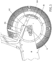
- An exercise device 1 of the present invention includes a main body 10, two fan wheels 20 and a magnetic resistance assembly 30.
- the main body 10 includes an axle 11 disposed thereon.
- the two fan wheels 20 are connected to the axle 11 and rotatable relative to the main body 10.
- the magnetic resistance assembly 30 includes two magnetoresistive rings 31 disposed respectively on the two fan wheels 20 and around the axle 11, a magnetic unit 32 and a controlling unit 33.
- the magnetic unit 32 includes two magnetic portions 321 respectively corresponding to the two magnetoresistive rings 31.
- the controlling unit 33 includes a lever 331 rotatably disposed on the main body 10 at a pivot point 332, and the magnetic unit 32 and an operating portion 333 are disposed on the lever 331 and located by two opposite sides with respect to the pivot point 332.
- the pivot point 332 and the axle 11 are eccentrically arranged.
- Movement of the two magnetic portions 321 driven by the lever 331 changes magnetic active force between the two magnetic portions 321 and the two magnetoresistive rings 31. Therefore, the two fan wheels 20 and the magnetic resistance assembly 30 provide sufficient operating resistance and the magnetic resistance assembly 30 has a simple structure and is easy to adjust.
- the lever 331 includes a first end 334 and a second end 335 located at two opposite sides of the pivot point 332.
- the magnetic unit 32 is disposed at the first end 334, the operating portion 333 is disposed at the second end 335, and the second end 335 is adjustably positioned on the main body 10.
- the main body 10 further has a first engaging portion 12, and the second end 335 has a second engaging portion 336 which is engageable with the first engaging portion 12 so as to adjustably position the magnetic unit 32.
- one of the first engaging portion 12 and the second engaging portion 336 includes at least one engaging convex, and the other of the first engaging portion 12 and the second engaging portion 336 includes at least one engaging concave.
- the first engaging portion 12 includes a plurality of said engaging concaves 121 spacingly disposed on the main body 10, and the second engaging portion 336 includes one said engaging convex 337 protruding toward the first engaging portion 12, which has a simple structure and is easy to operate.
- a distance between the magnetic unit 32 and the pivot point 332 is shorter than a distance between the operating portion 333 and the pivot point 332 so that a swinging path of the operating portion 333 is longer than a swinging path of the magnetic unit 32 and a position of the magnetic unit 32 is accurately and finely adjustable.
- the distance between the magnetic unit and the pivot point may be equal to or larger than the distance between the operating portion and the pivot point.
- the two magnetoresistive rings 31 are made of magnetic metal so as to generate magnetic resistance with the magnetic unit 32 during rotation.
- Each of the two magnetoresistive rings 31 includes a plurality of segments 311 and a plurality of connecting members 312, and each of the plurality of connecting members 312 detachably connects adjacent two of the plurality of segments 311, which is easy to assemble, maintain and replace.
- the two magnetoresistive rings may be integrally made in one piece, respectively.
- the plurality of connecting members 312 are detachably connected between the two fan wheels 20 and the two magnetoresistive rings 31.
- each of the two fan wheels 20 and one of the two magnetoresistive rings 31 are spacingly connected with each other by part of the plurality of connecting members 312 so that the two magnetoresistive rings 31 are axially closer to the two magnetic portions 321 for preferable magnetic resistance effect.
- each of the two magnetic portions 321 includes a receiving member 324 which is detachably disposed on the base 322 and has a plurality of recessions 325 receiving the at least one magnet 323 so that the receiving member 324 is replaceable to receive magnets with different shapes and a number of the at least one magnet 323 received within the plurality of recessions 325 are adjustable according using requirements; arrangement of the plurality of recessions 325 corresponds to the part of one of the two magnetoresistive rings 31.
- the at least one magnet may have a shape corresponding to the part of one of the two magnetoresistive rings and be directly attached to the base.
- the two magnetic portions 321 are movable relative to the two magnetoresistive rings 31 between a first position and a second position.
- the at least one magnet 323 of each of the two magnetic portions 321 is entirely axially overlapped with the two magnetoresistive rings 31 so as to provide maximum magnetic resistance between the two magnetic portions 321 and the two magnetoresistive rings 31 , as shown in figure 5 ; when the magnetic portions 321 are in the second position, the at least one magnet 323 of each of the two magnetic portions 321 is axially dislocated with the two magnetoresistive rings 31 so as to provide minimum magnetic resistance between the two magnetic portions 321 and the two magnetoresistive rings 31 , as shown in figure 6 .
- the exercise device 1 further includes a casing 40 and two protecting grilles 50.
- the casing 40 is disposed on the main body 10 and surrounds the two fan wheels 20, and the two protecting grilles 50 are detachably disposed on two opposite sides of the casing 40 and cover the two fan wheels 20, which allows air circulation and avoids direct contact with the two fan wheels 20.
- the two protecting grilles may be directly connected with each other without the casing.
Landscapes
- Health & Medical Sciences (AREA)
- General Health & Medical Sciences (AREA)
- Physical Education & Sports Medicine (AREA)
- Life Sciences & Earth Sciences (AREA)
- Biophysics (AREA)
- Orthopedic Medicine & Surgery (AREA)
- Cardiology (AREA)
- Vascular Medicine (AREA)
- Physics & Mathematics (AREA)
- Electromagnetism (AREA)
- Dynamo-Electric Clutches, Dynamo-Electric Brakes (AREA)
- Motorcycle And Bicycle Frame (AREA)
Claims (10)
- Übungsgerät (1), umfassend:einen Hauptkörper (10), der eine darauf angeordnete Achse (11) enthält;zwei Lüfterräder (20), die mit der Achse (11) verbunden und relativ zum Hauptkörper (10) drehbar sind;eine magnetische Widerstandsbaugruppe (30), die zwei magnetoresistive Ringe (31), die jeweils auf den beiden Lüfterrädern (20) und um die Achse (11) herum angeordnet sind, eine magnetische Einheit (32) und eine Steuereinheit (33) umfasst, wobei die magnetische Einheit (32) zwei magnetische Abschnitte (321) umfasst, die jeweils den beiden magnetoresistiven Ringen (31) entsprechen,wobei die Steuereinheit (33) einen Hebel (331) umfasst, der drehbar auf dem Hauptkörper (10) an einem Drehpunkt (332) angeordnet ist, und die magnetische Einheit (32) und ein Betätigungsabschnitt (333) auf dem Hebel (331) angeordnet sind und sich an zwei gegenüberliegenden Seiten in Bezug auf den Drehpunkt (332) befinden, wobei der Drehpunkt (332) exzentrisch in Bezug auf die Achse (11) angeordnet ist, wobei die Bewegung der beiden magnetischen Abschnitte (321), die durch den Hebel (331) angetrieben werden, die magnetische aktive Kraft zwischen den beiden magnetischen Abschnitten (321) und den beiden magnetoresistiven Ringen (31) verändert.
- Übungsgerät (1) nach Anspruch 1, wobei der Hebel (331) ein erstes Ende (334) und ein zweites Ende (335) aufweist, die sich an zwei gegenüberliegenden Seiten des Drehpunkts (332) befinden, die Magneteinheit (32) am ersten Ende (334) angeordnet ist, der Betätigungsabschnitt (333) am zweiten Ende (335) angeordnet ist und das zweite Ende (335) einstellbar am Hauptkörper (10) positioniert ist.
- Übungsgerät (1) nach Anspruch 2, wobei der Hauptkörper (10) ferner einen ersten Eingriffsabschnitt (12) aufweist und das zweite Ende (335) einen zweiten Eingriffsabschnitt (336) aufweist, der mit dem ersten Eingriffsabschnitt (12) in Eingriff bringbar ist.
- Übungsgerät (1) nach Anspruch 1, wobei ein Abstand zwischen der Magneteinheit (32) und dem Drehpunkt (332) kürzer ist als ein Abstand zwischen dem Betätigungsabschnitt (333) und dem Drehpunkt (332).
- Übungsgerät (1) nach Anspruch 1, wobei jeder der beiden magnetoresistiven Ringe (31) eine Vielzahl von Segmenten (311) und eine Vielzahl von Verbindungselementen (312) aufweist und jedes der Vielzahl von Verbindungselementen (312) zwei benachbarte der Vielzahl von Segmenten (311) verbindet.
- Übungsgerät (1) nach Anspruch 5, wobei die Vielzahl von Verbindungselementen (312) lösbar zwischen den beiden Lüfterrädern (20) und den beiden magnetoresistiven Ringen (31) verbunden sind.
- Übungsgerät (1) nach Anspruch 1, wobei die magnetische Einheit (32) ferner eine Basis (322) aufweist, die zwischen den beiden magnetoresistiven Ringen (31) angeordnet und mit dem Hebel (331) verbunden ist, und die beiden magnetischen Abschnitte (321) auf zwei gegenüberliegenden Seiten der Basis (322) angeordnet sind und jeweils mindestens einen Magneten (323) aufweisen.
- Übungsgerät (1) nach Anspruch 1, wobei die beiden magnetischen Abschnitte (321) jeweils mindestens einen Magneten (323) aufweisen, der eine Anordnung hat, die einem Teil eines der beiden magnetoresistiven Ringe (31) entspricht, wobei die beiden magnetischen Abschnitte (321) relativ zu den beiden magnetoresistiven Ringen (31) zwischen einer ersten Position und einer zweiten Position bewegbar sind; wenn sich die beiden magnetischen Abschnitte (321) in der ersten Position befinden, ist der mindestens eine Magnet (323) jedes der beiden magnetischen Abschnitte (321) vollständig axial mit den beiden magnetoresistiven Ringen (31) überlappt; wenn sich die magnetischen Abschnitte (321) in der zweiten Position befinden, ist der mindestens eine Magnet (323) jedes der beiden magnetischen Abschnitte (321) axial mit den beiden magnetoresistiven Ringen (31) disloziert.
- Übungsgerät (1) nach Anspruch 1, ferner mit einem Gehäuse (40) und zwei Schutzgittern (50), wobei das Gehäuse (40) an dem Hauptkörper (10) angeordnet ist und die beiden Lüfterräder (20) umgibt und die beiden Schutzgitter (50) an zwei gegenüberliegenden Seiten des Gehäuses (40) abnehmbar angeordnet sind und die beiden Lüfterräder (20) abdecken.
- Übungsgerät (1) nach Anspruch 3, wobei ein Abstand zwischen der Magneteinheit (32) und dem Drehpunkt (332) kürzer ist als ein Abstand zwischen dem Betätigungsabschnitt (333) und dem Drehpunkt (332); wobei jeder der beiden magnetoresistiven Ringe (31) eine Vielzahl von Segmenten (311) und eine Vielzahl von Verbindungselementen (312) beinhaltet, und jedes der Vielzahl von Verbindungselementen (312) zwei benachbarte der Vielzahl von Segmenten (311) lösbar verbindet; wobei die Vielzahl von Verbindungselementen (312) lösbar zwischen den beiden Lüfterrädern (20) und den beiden magnetoresistiven Ringen (31) verbunden ist; wobei die magnetische Einheit (32) ferner eine Basis (322) aufweist, die zwischen den beiden magnetoresistiven Ringen (31) angeordnet und einstückig mit dem Hebel (331) verbunden ist, und die beiden magnetischen Abschnitte (321) auf zwei gegenüberliegenden Seiten der Basis (322) angeordnet sind und jeweils mindestens einen Magneten (323) aufweisen, der eine Anordnung hat, die einem Teil eines der beiden magnetoresistiven Ringe (31) entspricht, wobei die beiden magnetischen Abschnitte (321) relativ zu den beiden magnetoresistiven Ringen (31) zwischen einer ersten Position und einer zweiten Position bewegbar sind; wenn sich die beiden magnetischen Abschnitte (321) in der ersten Position befinden, ist der mindestens eine Magnet (323) jedes der beiden magnetischen Abschnitte (321) vollständig axial mit den beiden magnetoresistiven Ringen (31) überlappt; wenn die magnetischen Abschnitte (321) in der zweiten Position sind, ist der mindestens eine Magnet (323) von jedem der zwei magnetischen Abschnitte (321) axial zu den zwei magnetoresistiven Ringen (31) versetzt, wobei die zwei magnetoresistiven Ringe (31) aus magnetischem Metall hergestellt sind, wobei jeder der beiden magnetischen Abschnitte (321) ein Aufnahmeelement (324) aufweist, das lösbar an der Basis (322) angeordnet ist und eine Vielzahl von Ausnehmungen (325) aufweist, die den mindestens einen Magneten (323) aufnehmen, wobei die Anordnung der Vielzahl von Ausnehmungen (325) dem Teil eines der beiden magnetoresistiven Ringe (31) entspricht, wobei das Übungsgerät (1) ferner ein Gehäuse (40) und zwei Schutzgitter (50) aufweist, das Gehäuse (40) an dem Hauptkörper (10) angeordnet ist und die beiden Lüfterräder (20) umgibt, und die beiden Schutzgitter (50) an zwei gegenüberliegenden Seiten des Gehäuses (40) abnehmbar angeordnet sind und die beiden Lüfterräder (20) abdecken, wobei einer von dem ersten Eingriffsabschnitt (12) und dem zweiten Eingriffsabschnitt (336) mindestens eine konvexe Eingriffsfläche aufweist, und der andere von dem ersten Eingriffsabschnitt (12) und dem zweiten Eingriffsabschnitt (336) mindestens eine konkave Eingriffsfläche aufweist.
Priority Applications (2)
| Application Number | Priority Date | Filing Date | Title |
|---|---|---|---|
| EP20150610.2A EP3848097B1 (de) | 2020-01-07 | 2020-01-07 | Übungsvorrichtung |
| PL20150610.2T PL3848097T3 (pl) | 2020-01-07 | 2020-01-07 | Przyrząd do ćwiczeń |
Applications Claiming Priority (1)
| Application Number | Priority Date | Filing Date | Title |
|---|---|---|---|
| EP20150610.2A EP3848097B1 (de) | 2020-01-07 | 2020-01-07 | Übungsvorrichtung |
Publications (2)
| Publication Number | Publication Date |
|---|---|
| EP3848097A1 EP3848097A1 (de) | 2021-07-14 |
| EP3848097B1 true EP3848097B1 (de) | 2022-06-22 |
Family
ID=69147490
Family Applications (1)
| Application Number | Title | Priority Date | Filing Date |
|---|---|---|---|
| EP20150610.2A Active EP3848097B1 (de) | 2020-01-07 | 2020-01-07 | Übungsvorrichtung |
Country Status (2)
| Country | Link |
|---|---|
| EP (1) | EP3848097B1 (de) |
| PL (1) | PL3848097T3 (de) |
Family Cites Families (4)
| Publication number | Priority date | Publication date | Assignee | Title |
|---|---|---|---|---|
| TWM511345U (zh) * | 2015-04-09 | 2015-11-01 | Keen Neek Co Ltd | 可調整磁阻的風扇阻尼裝置 |
| US10537764B2 (en) * | 2015-08-07 | 2020-01-21 | Icon Health & Fitness, Inc. | Emergency stop with magnetic brake for an exercise device |
| CN206745848U (zh) * | 2017-05-15 | 2017-12-15 | 环玮健康科技国际企业股份有限公司 | 可调变阻力的风扇车 |
| US10561878B2 (en) * | 2018-02-22 | 2020-02-18 | Mu-Chuan Wu | Resistance adjusting apparatus with wind resistance and magnetic resistance |
-
2020
- 2020-01-07 EP EP20150610.2A patent/EP3848097B1/de active Active
- 2020-01-07 PL PL20150610.2T patent/PL3848097T3/pl unknown
Also Published As
| Publication number | Publication date |
|---|---|
| EP3848097A1 (de) | 2021-07-14 |
| PL3848097T3 (pl) | 2022-10-17 |
Similar Documents
| Publication | Publication Date | Title |
|---|---|---|
| US11147998B2 (en) | Exercise device | |
| US9138614B2 (en) | Exercise assemblies having linear motion synchronizing mechanism | |
| US9050498B2 (en) | Exercise assemblies having foot pedal members that are movable along user defined paths | |
| EP3341090B1 (de) | Pedalweg einer stepmaschine | |
| US6964633B2 (en) | Exercise device with an adjustable magnetic resistance arrangement | |
| WO2002068064A3 (en) | Swing exerciser | |
| US10561878B2 (en) | Resistance adjusting apparatus with wind resistance and magnetic resistance | |
| EP3848097B1 (de) | Übungsvorrichtung | |
| US9643044B1 (en) | Damping device for exercise equipment | |
| US20180185700A1 (en) | Stair steppers | |
| US11779802B2 (en) | Fitness machine and resistance device thereof | |
| US20070203000A1 (en) | Flywheel magnetic control resistance apparatus for indoor exercise facilities | |
| US9427620B2 (en) | Exercise machine | |
| TWI695726B (zh) | 固定健身車之主、被動外轉式磁控模組系統 | |
| CN211836092U (zh) | 健身车 | |
| TWI651114B (zh) | 風阻併磁阻式阻力調整裝置 | |
| TWI682797B (zh) | 運動復健器材之主、被動內轉式磁控模組系統 | |
| CN201049168Y (zh) | 磁控椭圆风扇健身车 | |
| US6682465B2 (en) | Swing training and exercising apparatus | |
| TWM638705U (zh) | 運動機及其阻力裝置 | |
| US20240408431A1 (en) | Asymmetrical resistance systems and methods for exercise equipment | |
| US11154748B2 (en) | Elliptical trainer | |
| US12257468B2 (en) | Fan bike providing magnetically controlled resistance | |
| CN219023122U (zh) | 运动机的阻力装置及该运动机 | |
| CN222969112U (zh) | 一种健身器材用阻力装置 |
Legal Events
| Date | Code | Title | Description |
|---|---|---|---|
| PUAI | Public reference made under article 153(3) epc to a published international application that has entered the european phase |
Free format text: ORIGINAL CODE: 0009012 |
|
| STAA | Information on the status of an ep patent application or granted ep patent |
Free format text: STATUS: REQUEST FOR EXAMINATION WAS MADE |
|
| 17P | Request for examination filed |
Effective date: 20210205 |
|
| AK | Designated contracting states |
Kind code of ref document: A1 Designated state(s): AL AT BE BG CH CY CZ DE DK EE ES FI FR GB GR HR HU IE IS IT LI LT LU LV MC MK MT NL NO PL PT RO RS SE SI SK SM TR |
|
| GRAP | Despatch of communication of intention to grant a patent |
Free format text: ORIGINAL CODE: EPIDOSNIGR1 |
|
| STAA | Information on the status of an ep patent application or granted ep patent |
Free format text: STATUS: GRANT OF PATENT IS INTENDED |
|
| INTG | Intention to grant announced |
Effective date: 20211129 |
|
| RIN1 | Information on inventor provided before grant (corrected) |
Inventor name: WANG, CHIN-LIU |
|
| GRAS | Grant fee paid |
Free format text: ORIGINAL CODE: EPIDOSNIGR3 |
|
| GRAA | (expected) grant |
Free format text: ORIGINAL CODE: 0009210 |
|
| STAA | Information on the status of an ep patent application or granted ep patent |
Free format text: STATUS: THE PATENT HAS BEEN GRANTED |
|
| AK | Designated contracting states |
Kind code of ref document: B1 Designated state(s): AL AT BE BG CH CY CZ DE DK EE ES FI FR GB GR HR HU IE IS IT LI LT LU LV MC MK MT NL NO PL PT RO RS SE SI SK SM TR |
|
| REG | Reference to a national code |
Ref country code: GB Ref legal event code: FG4D |
|
| REG | Reference to a national code |
Ref country code: CH Ref legal event code: EP |
|
| REG | Reference to a national code |
Ref country code: DE Ref legal event code: R096 Ref document number: 602020003584 Country of ref document: DE |
|
| REG | Reference to a national code |
Ref country code: AT Ref legal event code: REF Ref document number: 1499382 Country of ref document: AT Kind code of ref document: T Effective date: 20220715 |
|
| REG | Reference to a national code |
Ref country code: IE Ref legal event code: FG4D |
|
| REG | Reference to a national code |
Ref country code: NL Ref legal event code: FP |
|
| REG | Reference to a national code |
Ref country code: LT Ref legal event code: MG9D |
|
| PG25 | Lapsed in a contracting state [announced via postgrant information from national office to epo] |
Ref country code: SE Free format text: LAPSE BECAUSE OF FAILURE TO SUBMIT A TRANSLATION OF THE DESCRIPTION OR TO PAY THE FEE WITHIN THE PRESCRIBED TIME-LIMIT Effective date: 20220622 Ref country code: NO Free format text: LAPSE BECAUSE OF FAILURE TO SUBMIT A TRANSLATION OF THE DESCRIPTION OR TO PAY THE FEE WITHIN THE PRESCRIBED TIME-LIMIT Effective date: 20220922 Ref country code: LT Free format text: LAPSE BECAUSE OF FAILURE TO SUBMIT A TRANSLATION OF THE DESCRIPTION OR TO PAY THE FEE WITHIN THE PRESCRIBED TIME-LIMIT Effective date: 20220622 Ref country code: HR Free format text: LAPSE BECAUSE OF FAILURE TO SUBMIT A TRANSLATION OF THE DESCRIPTION OR TO PAY THE FEE WITHIN THE PRESCRIBED TIME-LIMIT Effective date: 20220622 Ref country code: GR Free format text: LAPSE BECAUSE OF FAILURE TO SUBMIT A TRANSLATION OF THE DESCRIPTION OR TO PAY THE FEE WITHIN THE PRESCRIBED TIME-LIMIT Effective date: 20220923 Ref country code: FI Free format text: LAPSE BECAUSE OF FAILURE TO SUBMIT A TRANSLATION OF THE DESCRIPTION OR TO PAY THE FEE WITHIN THE PRESCRIBED TIME-LIMIT Effective date: 20220622 Ref country code: BG Free format text: LAPSE BECAUSE OF FAILURE TO SUBMIT A TRANSLATION OF THE DESCRIPTION OR TO PAY THE FEE WITHIN THE PRESCRIBED TIME-LIMIT Effective date: 20220922 |
|
| REG | Reference to a national code |
Ref country code: AT Ref legal event code: MK05 Ref document number: 1499382 Country of ref document: AT Kind code of ref document: T Effective date: 20220622 |
|
| PG25 | Lapsed in a contracting state [announced via postgrant information from national office to epo] |
Ref country code: RS Free format text: LAPSE BECAUSE OF FAILURE TO SUBMIT A TRANSLATION OF THE DESCRIPTION OR TO PAY THE FEE WITHIN THE PRESCRIBED TIME-LIMIT Effective date: 20220622 Ref country code: LV Free format text: LAPSE BECAUSE OF FAILURE TO SUBMIT A TRANSLATION OF THE DESCRIPTION OR TO PAY THE FEE WITHIN THE PRESCRIBED TIME-LIMIT Effective date: 20220622 |
|
| PG25 | Lapsed in a contracting state [announced via postgrant information from national office to epo] |
Ref country code: SM Free format text: LAPSE BECAUSE OF FAILURE TO SUBMIT A TRANSLATION OF THE DESCRIPTION OR TO PAY THE FEE WITHIN THE PRESCRIBED TIME-LIMIT Effective date: 20220622 Ref country code: SK Free format text: LAPSE BECAUSE OF FAILURE TO SUBMIT A TRANSLATION OF THE DESCRIPTION OR TO PAY THE FEE WITHIN THE PRESCRIBED TIME-LIMIT Effective date: 20220622 Ref country code: RO Free format text: LAPSE BECAUSE OF FAILURE TO SUBMIT A TRANSLATION OF THE DESCRIPTION OR TO PAY THE FEE WITHIN THE PRESCRIBED TIME-LIMIT Effective date: 20220622 Ref country code: PT Free format text: LAPSE BECAUSE OF FAILURE TO SUBMIT A TRANSLATION OF THE DESCRIPTION OR TO PAY THE FEE WITHIN THE PRESCRIBED TIME-LIMIT Effective date: 20221024 Ref country code: ES Free format text: LAPSE BECAUSE OF FAILURE TO SUBMIT A TRANSLATION OF THE DESCRIPTION OR TO PAY THE FEE WITHIN THE PRESCRIBED TIME-LIMIT Effective date: 20220622 Ref country code: EE Free format text: LAPSE BECAUSE OF FAILURE TO SUBMIT A TRANSLATION OF THE DESCRIPTION OR TO PAY THE FEE WITHIN THE PRESCRIBED TIME-LIMIT Effective date: 20220622 Ref country code: CZ Free format text: LAPSE BECAUSE OF FAILURE TO SUBMIT A TRANSLATION OF THE DESCRIPTION OR TO PAY THE FEE WITHIN THE PRESCRIBED TIME-LIMIT Effective date: 20220622 Ref country code: AT Free format text: LAPSE BECAUSE OF FAILURE TO SUBMIT A TRANSLATION OF THE DESCRIPTION OR TO PAY THE FEE WITHIN THE PRESCRIBED TIME-LIMIT Effective date: 20220622 |
|
| PG25 | Lapsed in a contracting state [announced via postgrant information from national office to epo] |
Ref country code: IS Free format text: LAPSE BECAUSE OF FAILURE TO SUBMIT A TRANSLATION OF THE DESCRIPTION OR TO PAY THE FEE WITHIN THE PRESCRIBED TIME-LIMIT Effective date: 20221022 |
|
| REG | Reference to a national code |
Ref country code: DE Ref legal event code: R097 Ref document number: 602020003584 Country of ref document: DE |
|
| PG25 | Lapsed in a contracting state [announced via postgrant information from national office to epo] |
Ref country code: AL Free format text: LAPSE BECAUSE OF FAILURE TO SUBMIT A TRANSLATION OF THE DESCRIPTION OR TO PAY THE FEE WITHIN THE PRESCRIBED TIME-LIMIT Effective date: 20220622 |
|
| PG25 | Lapsed in a contracting state [announced via postgrant information from national office to epo] |
Ref country code: DK Free format text: LAPSE BECAUSE OF FAILURE TO SUBMIT A TRANSLATION OF THE DESCRIPTION OR TO PAY THE FEE WITHIN THE PRESCRIBED TIME-LIMIT Effective date: 20220622 |
|
| PLBE | No opposition filed within time limit |
Free format text: ORIGINAL CODE: 0009261 |
|
| STAA | Information on the status of an ep patent application or granted ep patent |
Free format text: STATUS: NO OPPOSITION FILED WITHIN TIME LIMIT |
|
| 26N | No opposition filed |
Effective date: 20230323 |
|
| PG25 | Lapsed in a contracting state [announced via postgrant information from national office to epo] |
Ref country code: SI Free format text: LAPSE BECAUSE OF FAILURE TO SUBMIT A TRANSLATION OF THE DESCRIPTION OR TO PAY THE FEE WITHIN THE PRESCRIBED TIME-LIMIT Effective date: 20220622 |
|
| REG | Reference to a national code |
Ref country code: CH Ref legal event code: PL |
|
| PG25 | Lapsed in a contracting state [announced via postgrant information from national office to epo] |
Ref country code: LU Free format text: LAPSE BECAUSE OF NON-PAYMENT OF DUE FEES Effective date: 20230107 |
|
| PG25 | Lapsed in a contracting state [announced via postgrant information from national office to epo] |
Ref country code: LI Free format text: LAPSE BECAUSE OF NON-PAYMENT OF DUE FEES Effective date: 20230131 Ref country code: CH Free format text: LAPSE BECAUSE OF NON-PAYMENT OF DUE FEES Effective date: 20230131 |
|
| PG25 | Lapsed in a contracting state [announced via postgrant information from national office to epo] |
Ref country code: IT Free format text: LAPSE BECAUSE OF FAILURE TO SUBMIT A TRANSLATION OF THE DESCRIPTION OR TO PAY THE FEE WITHIN THE PRESCRIBED TIME-LIMIT Effective date: 20220622 Ref country code: IE Free format text: LAPSE BECAUSE OF NON-PAYMENT OF DUE FEES Effective date: 20230107 |
|
| PG25 | Lapsed in a contracting state [announced via postgrant information from national office to epo] |
Ref country code: MC Free format text: LAPSE BECAUSE OF FAILURE TO SUBMIT A TRANSLATION OF THE DESCRIPTION OR TO PAY THE FEE WITHIN THE PRESCRIBED TIME-LIMIT Effective date: 20220622 |
|
| PG25 | Lapsed in a contracting state [announced via postgrant information from national office to epo] |
Ref country code: MC Free format text: LAPSE BECAUSE OF FAILURE TO SUBMIT A TRANSLATION OF THE DESCRIPTION OR TO PAY THE FEE WITHIN THE PRESCRIBED TIME-LIMIT Effective date: 20220622 |
|
| PG25 | Lapsed in a contracting state [announced via postgrant information from national office to epo] |
Ref country code: BG Free format text: LAPSE BECAUSE OF FAILURE TO SUBMIT A TRANSLATION OF THE DESCRIPTION OR TO PAY THE FEE WITHIN THE PRESCRIBED TIME-LIMIT Effective date: 20220622 |
|
| PG25 | Lapsed in a contracting state [announced via postgrant information from national office to epo] |
Ref country code: BG Free format text: LAPSE BECAUSE OF FAILURE TO SUBMIT A TRANSLATION OF THE DESCRIPTION OR TO PAY THE FEE WITHIN THE PRESCRIBED TIME-LIMIT Effective date: 20220622 |
|
| PG25 | Lapsed in a contracting state [announced via postgrant information from national office to epo] |
Ref country code: CY Free format text: LAPSE BECAUSE OF FAILURE TO SUBMIT A TRANSLATION OF THE DESCRIPTION OR TO PAY THE FEE WITHIN THE PRESCRIBED TIME-LIMIT; INVALID AB INITIO Effective date: 20200107 |
|
| PG25 | Lapsed in a contracting state [announced via postgrant information from national office to epo] |
Ref country code: HU Free format text: LAPSE BECAUSE OF FAILURE TO SUBMIT A TRANSLATION OF THE DESCRIPTION OR TO PAY THE FEE WITHIN THE PRESCRIBED TIME-LIMIT; INVALID AB INITIO Effective date: 20200107 |
|
| PG25 | Lapsed in a contracting state [announced via postgrant information from national office to epo] |
Ref country code: TR Free format text: LAPSE BECAUSE OF FAILURE TO SUBMIT A TRANSLATION OF THE DESCRIPTION OR TO PAY THE FEE WITHIN THE PRESCRIBED TIME-LIMIT Effective date: 20220622 |
|
| PGFP | Annual fee paid to national office [announced via postgrant information from national office to epo] |
Ref country code: GB Payment date: 20251211 Year of fee payment: 7 |
|
| PGFP | Annual fee paid to national office [announced via postgrant information from national office to epo] |
Ref country code: PL Payment date: 20251203 Year of fee payment: 7 |
|
| PGFP | Annual fee paid to national office [announced via postgrant information from national office to epo] |
Ref country code: NL Payment date: 20260126 Year of fee payment: 7 |
|
| PGFP | Annual fee paid to national office [announced via postgrant information from national office to epo] |
Ref country code: DE Payment date: 20260128 Year of fee payment: 7 |
|
| PGFP | Annual fee paid to national office [announced via postgrant information from national office to epo] |
Ref country code: BE Payment date: 20260127 Year of fee payment: 7 |
|
| PGFP | Annual fee paid to national office [announced via postgrant information from national office to epo] |
Ref country code: FR Payment date: 20260126 Year of fee payment: 7 |