EP3847943A1 - Spraying apparatus and dish-washing machine - Google Patents
Spraying apparatus and dish-washing machine Download PDFInfo
- Publication number
- EP3847943A1 EP3847943A1 EP18936967.1A EP18936967A EP3847943A1 EP 3847943 A1 EP3847943 A1 EP 3847943A1 EP 18936967 A EP18936967 A EP 18936967A EP 3847943 A1 EP3847943 A1 EP 3847943A1
- Authority
- EP
- European Patent Office
- Prior art keywords
- transmission wheel
- water
- spraying
- linkage
- pipe
- Prior art date
- Legal status (The legal status is an assumption and is not a legal conclusion. Google has not performed a legal analysis and makes no representation as to the accuracy of the status listed.)
- Granted
Links
Images


Classifications
-
- A—HUMAN NECESSITIES
- A47—FURNITURE; DOMESTIC ARTICLES OR APPLIANCES; COFFEE MILLS; SPICE MILLS; SUCTION CLEANERS IN GENERAL
- A47L—DOMESTIC WASHING OR CLEANING; SUCTION CLEANERS IN GENERAL
- A47L15/00—Washing or rinsing machines for crockery or tableware
- A47L15/42—Details
- A47L15/4278—Nozzles
- A47L15/428—Rotary nozzles
-
- A—HUMAN NECESSITIES
- A47—FURNITURE; DOMESTIC ARTICLES OR APPLIANCES; COFFEE MILLS; SPICE MILLS; SUCTION CLEANERS IN GENERAL
- A47L—DOMESTIC WASHING OR CLEANING; SUCTION CLEANERS IN GENERAL
- A47L15/00—Washing or rinsing machines for crockery or tableware
- A47L15/42—Details
- A47L15/4278—Nozzles
- A47L15/4282—Arrangements to change or modify spray pattern or direction
-
- A—HUMAN NECESSITIES
- A47—FURNITURE; DOMESTIC ARTICLES OR APPLIANCES; COFFEE MILLS; SPICE MILLS; SUCTION CLEANERS IN GENERAL
- A47L—DOMESTIC WASHING OR CLEANING; SUCTION CLEANERS IN GENERAL
- A47L15/00—Washing or rinsing machines for crockery or tableware
- A47L15/14—Washing or rinsing machines for crockery or tableware with stationary crockery baskets and spraying devices within the cleaning chamber
- A47L15/18—Washing or rinsing machines for crockery or tableware with stationary crockery baskets and spraying devices within the cleaning chamber with movably-mounted spraying devices
- A47L15/22—Rotary spraying devices
-
- A—HUMAN NECESSITIES
- A47—FURNITURE; DOMESTIC ARTICLES OR APPLIANCES; COFFEE MILLS; SPICE MILLS; SUCTION CLEANERS IN GENERAL
- A47L—DOMESTIC WASHING OR CLEANING; SUCTION CLEANERS IN GENERAL
- A47L15/00—Washing or rinsing machines for crockery or tableware
- A47L15/42—Details
- A47L15/4214—Water supply, recirculation or discharge arrangements; Devices therefor
- A47L15/4217—Fittings for water supply, e.g. valves or plumbing means to connect to cold or warm water lines, aquastops
-
- A—HUMAN NECESSITIES
- A47—FURNITURE; DOMESTIC ARTICLES OR APPLIANCES; COFFEE MILLS; SPICE MILLS; SUCTION CLEANERS IN GENERAL
- A47L—DOMESTIC WASHING OR CLEANING; SUCTION CLEANERS IN GENERAL
- A47L15/00—Washing or rinsing machines for crockery or tableware
- A47L15/42—Details
- A47L15/4214—Water supply, recirculation or discharge arrangements; Devices therefor
- A47L15/4225—Arrangements or adaption of recirculation or discharge pumps
-
- A—HUMAN NECESSITIES
- A47—FURNITURE; DOMESTIC ARTICLES OR APPLIANCES; COFFEE MILLS; SPICE MILLS; SUCTION CLEANERS IN GENERAL
- A47L—DOMESTIC WASHING OR CLEANING; SUCTION CLEANERS IN GENERAL
- A47L15/00—Washing or rinsing machines for crockery or tableware
- A47L15/42—Details
- A47L15/4278—Nozzles
Definitions
- the present application relates to the technical field of a dish-washing machine, and in particular to a spray washer and a dish-washing machine.
- the spraying structure of the dish-washing machine in the market usually rotates by an elongate spraying arm structure. Since the rotation of the spraying arm is driven by a motor, the rotation angle of the spraying arm during rotation is difficult to be accurately controlled, which is not conductive to accurate spray washing of the tableware with the water sprayed by the spraying arm, so that the utilization of water is decreased.
- the main object of the present application is to provide a spray washer, which is intended to improve the rotation accuracy of spraying pipes, so as to increase the utilization of water.
- a spray washer proposed in the present application includes:
- the power source includes a driving motor.
- the driving gear is fixedly connected to a rotating shaft of the driving motor.
- the spray washer includes a plurality of spraying pipes.
- the spray washer further includes a first transmission wheel and a first linkage.
- One end of one of the spraying pipes is connected to the first transmission wheel, and the other end of the spraying pipe is in communication with a water source.
- One end of the first linkage is hinged to the driven gear, and the other end of the first linkage is hinged to the first transmission wheel, to drive the spraying pipe and the first transmission wheel into rotation with rotation of the driven gear.
- the spraying pipe is connected to a middle portion of the first transmission wheel.
- One end of the first linkage is connected to an upper portion or a lower portion of the first transmission wheel, and the other end of the first linkage is connected to an upper portion or a lower portion of the driven gear.
- the spray washer further includes a second transmission wheel and a second linkage.
- One end of one of the spraying pipes is connected to the second transmission wheel, and the other end of the spraying pipe is in communication with the water source.
- One end of the second linkage is hinged to the first transmission wheel, and the other end of the second linkage is hinged to the second transmission wheel, to drive the spraying pipe and the second transmission wheel into rotation with the rotation of the first transmission wheel.
- the spraying pipe is connected to a middle portion of the second transmission wheel.
- Said one end of the second linkage is connected to an upper portion or a lower portion of the first transmission wheel, and said the other end of the second linkage is connected to an upper portion or a lower portion of the second transmission wheel.
- the spray washer includes a water supply assembly.
- the water supply assembly includes a water pump, a water feeding pipe and a plurality of water distributing pipes.
- One end of the water feeding pipe is in communication with the water pump, and the other end of the water feeding pipe is in communication with water distributing pipes.
- Each water distributing pipe away from the water feeding pipe is in communication with one of the spraying pipes.
- the water supply assembly is located below the spraying pipes, and each water distributing pipe is arranged around the water feeding pipe after being bent.
- the spray washer further includes a reinforcing plate.
- the reinforcing plate is connected to the water distributing pipes along an arrangement direction of the water distributing pipes, and is provided with a fixing portion for fixing the reinforcing plate.
- a rotation angle between an initial rotation position and an end rotation position of each spraying pipe is no less than 100° and no more than 150°.
- the present application further provides a dish-washing machine.
- the dish-washing machine includes:
- the spray washer includes:
- the dish-washing machine includes a bowl basket arranged within the inner container.
- Each spraying pipe is provided with a plurality of water injection nozzles, which are arranged along a length direction of each spraying pipe corresponding to a position of the bowl basket.
- the driving force of the driving mechanism is transmitted to the spraying pipes through the driving gear and the driven gear, so that the spraying pipes rotate along an axial axis thereof, and water is sprayed from the water injection nozzles on each spraying pipe.
- a spray washing area is formed. Since the spraying pipes are driven by a gear structure, both the rotation of the spraying pipes and the transmission of power are very stable and reliable. Meanwhile, the rotation angle of each spraying pipe can be accurately controlled, so as to control the change of the spray washing area, so that the spray washer can accurately control the spraying area, which facilitates improving the accuracy of the spray washer for spray washing the tableware, and increasing the utilization of water and cleaning efficiency.
- first and second are used for descriptive purposes only and cannot be appreciated as indicating or implying their relative importance or implicitly indicating the number of indicated technical features.
- features defining “first” and “second” may explicitly or implicitly include at least one such feature.
- technical solutions between the various embodiments may be combined with each other, but must be based on what one of ordinary skill in the art can achieve. When the combination of technical solutions is contradictory or impossible to achieve, it should be considered that the combination of such technical solutions does not exist and is not within the protection scope required by the present application.
- the present application mainly provides a spray washer, which is mainly applied to a dish-washing machine, so as to increase the utilization of water and the tableware cleaning efficiency of the dish-washing machine.
- the spray washer includes:
- the spraying pipe 100 is configured as a columnar pipe.
- the spraying pipe includes a water inlet end 110 and a driving end 120. That is, the water inlet structure of the spraying pipe 100 is provided at one end of the spraying pipe 100 and the driving structure of the spraying pipe 100 is provided at the other end of the spraying pipe 100, so that the driving structure and the water inlet structure do not interfere with each other.
- the driving structure and the water inlet structure may also be provided at the same end of the spraying pipe 100.
- the driving end 120 of the spraying pipe 100 is closed, and the water is discharged from the water injection nozzle after the water enters from the water inlet end 110.
- the water injection nozzle is provided on the pipe wall of the spraying pipe 100, so that the water flow may be directly sprayed from the water injection nozzle.
- a sprinkler may also be installed in the water injection nozzle, so that the water may be sprayed from the sprinkler.
- the driven gear 320 may be directly provided around the driving end 120.
- a driven shaft can be provided on the driving end, and the driven gear 320 is provided around the driven shaft.
- the axis of rotation of the driven gear 320 is collinear with the axial axis of the spraying pipe 100.
- the driving gear 310 meshes with the driven gear 320.
- the position that the driving gear is located below the driven gear 320 is taken as an example. Taking an upward spraying direction as an example, the driving gear 310 is arranged below the driven gear so as to avoid affecting the cleaning of the tableware.
- the driving gear 310 and the driven gear 320 are both spur gears.
- the driving mechanism 200 has a driving shaft.
- the driving shaft is directly inserted into the driving gear 310, or connected to the driving gear 310 after being decelerated by the transmission structure 300.
- the driving gear 310 rotates through the driving shaft as a rotating shaft.
- the driving mechanism 200 takes a driving motor as an example, the driving gear 310 is fixedly connected to the rotating shaft of the driving motor.
- the driving force of the driving mechanism 200 is transmitted to the spraying pipe 100 through the driving gear 310 and the driven gear 320, so that the spraying pipe 100 rotates along an axial axis thereof, and water is sprayed from the water injection nozzle on the spraying pipe 100.
- a spray washing area is formed. Since the spraying pipe 100 is driven by a gear structure, both the rotation of the spraying pipe 100 and the transmission of power are very stable and reliable. Meanwhile, the rotation angle of the spraying pipe 100 can be accurately controlled, so as to control the change of the spray washing area, so that the spray washer can accurately control the spraying area, which facilitates improving the accuracy of the spray washer for spray washing the tableware, and increasing the utilization of water and cleaning efficiency.
- the rotation angle ⁇ of the spraying pipe 100 is from 100° to 150°, taking from 120° to 140° as an example.
- the rotation angle of the spraying pipe 100 is from 100° to 150°, taking from 120° to 140° as an example.
- the spray washer includes a plurality of spraying pipes 100.
- the spray washer further includes a first transmission wheel 610 and a first linkage 620.
- One end of one of the spraying pipes 100 is connected to the first transmission wheel 610, and the other end of the spraying pipe is in communication with a water source.
- One end of the first linkage 620 is hinged to the driven gear 320, and the other end of the first linkage is hinged to the first transmission wheel 610, to drive the spraying pipe 100 and the first transmission wheel into rotation with rotation of the driven gear 320.
- the spraying pipes 100 may be positioned at the front side, the rear side or on the top of the spraying pipe 100 connected to the driven gear 320.
- the spray washer includes a plurality of first linkages 620 and a plurality of first transmission wheels 610 connected to the first linkages 620.
- one driven gear 320 may simultaneously drive the plurality of first transmission wheel 610, to simultaneously drive the plurality of spraying pipes 100.
- One first transmission linkage and one first transmission wheel 610 are described in detail below.
- first linkage 620 is hinged to the driven gear 320, so that the first linkage 620 rotates with the rotation of the driven gear 320.
- the other end of the first linkage 620 is hinged to the first transmission wheel 610, so that the first linkage 620 transmits the rotation displacement of the driven gear 320 to the first transmission wheel 610, the first transmission wheel 610 converts the displacement of the first linkage 620 into the rotation displacement, and finally transmits the rotation displacement to the spraying pipes 100.
- the spraying pipes 100 rotate with rotation of the driven gear 320.
- one of the spraying pipes 100 is connected to a middle portion of the first transmission wheel 610.
- One end of the first linkage 620 is connected to an upper portion or a lower portion of the first transmission wheel 610, and the other end of the first linkage is connected to an upper portion or a lower portion of the driven gear 320.
- the connection between the spraying pipe 100 and the first transmission wheel 610 is similar to the connection between the driven gear 320 and the spraying pipe 100.
- the axis of rotation of the first transmission wheel is collinear with the axis of rotation of the spraying pipe 100.
- One end of the first linkage 620 is hinged to the top of the first transmission wheel 610, and the other end of the first linkage is hinged to the top of the driven gear 320.
- the rotation direction of the first transmission wheel 610 is the same as the rotation direction of the driven gear 320.
- the spray washer further includes a second transmission wheel 710 and a second linkage 720.
- One end of one of the spraying pipes 100 is connected to the second transmission wheel 720, and the other end of the spraying pipe is in communication with the water source.
- One end of the second linkage 720 is hinged to the first transmission wheel 610, and the other end of the second linkage is hinged to the second transmission wheel 710, to drive the spraying pipe 100 and the second transmission wheel into rotation with the rotation of the first transmission wheel.
- the second transmission wheel 710 is located on the top of the first transmission wheel 610, or at a side of the first transmission wheel away from the driven gear 320.
- the spray washer includes a plurality of second transmission wheels 710 and a plurality of second linkages 720. In this case, one first transmission wheel 610 may simultaneously drive the plurality of second transmission wheels 710.
- One second transmission linkage and one second transmission wheel 710 are described in detail below.
- One end of the second linkage 720 is hinged to the first transmission wheel 610, so that the second linkage 720 rotates with the rotation of the first transmission wheel 610.
- the other end of the second linkage 720 is hinged to the second transmission wheel 710, so that the second linkage 720 transmits the rotation displacement of the first transmission wheel 610 to the second transmission wheel 710, the second transmission wheel 710 converts the displacement of the second linkage 720 into the rotation displacement, and finally transmits the rotation displacement to the spraying pipes 100.
- the spraying pipes 100 rotate with rotation of the first transmission wheel 610.
- the spraying pipe 100 in order to better drive the spraying pipes 100, is connected to a middle portion of the second transmission wheel 710.
- One end of the second linkage 720 is connected to an upper portion or a lower portion of the first transmission wheel 610, and the other end of the second linkage is connected to an upper portion or a lower portion of the second transmission wheel.
- connection between the spraying pipe 100 and the second transmission wheel 710 is similar to the connection between the first transmission wheel 610 and the spraying pipe 100.
- the axis of rotation of the second transmission wheel 710 is collinear with the axis of rotation of the spraying pipe 100.
- One end of the second linkage 720 is hinged to the top of the second transmission wheel 710, and the other end of the second linkage is hinged to the top of the first transmission wheel 610.
- the rotation direction of the second transmission wheel 710 is the same as the rotation direction of the first transmission wheel 610.
- the spray washer includes a water supply assembly.
- the water supply assembly includes a water pump 400, a water feeding pipe 510 and a plurality of water distributing pipes 520.
- One end of the water feeding pipe 510 is in communication with the water pump 400, and the other end of the water feeding pipe is in communication with water distributing pipes 520.
- One end of each water distributing pipe 520 away from the water feeding pipe 510 is in communication with one of the spraying pipes 100.
- One end of the water feeding pipe 510 is in communication with the water pump 400, and another end of the water feeding pipe is in communication with the water distributing pipes 520.
- the water pump 400 pumps water from the water source to the water feeding pipe 510, and then the water feeding pipe 510 delivers water to the water distributing pipes 520.
- One end of each water distributing pipe 520 away from the water feeding pipe 510 is in communication with one of the spraying pipes 100. There are many ways of communication, such as surrounding, adapting through adapters, etc.
- the water supply assembly is located below the spraying pipes 100, and each water distributing pipe 520 is arranged around the water feeding pipe 510 after being bent.
- the spraying pipes 100 spray water upwardly, the water supply assembly below does not affect the spray washing of the spraying pipes 100, which ensures the effect of spray washing while fully utilizing the space.
- the spray washer further includes a reinforcing plate 530.
- the reinforcing plate 530 is connected to the water distributing pipes 520 along an arrangement direction of the water distributing pipes 520, and is provided with a fixing portion for fixing the reinforcing plate 530.
- the reinforcing plate 530 is fixedly connected to the inner container, so that the reinforcing plate 530 not only strengthens the strength and stability of the water distributing pipes 520, but also prevents the water distributing pipes 520 from swinging and vibrating greatly due to the impact of water flow by fixing the water distributing pipes 520, thereby effectively reducing the noise generated by the swinging and vibrating of the water distributing pipes 520.
- the present application further provides a dish-washing machine.
- the dish-washing machine includes an inner container and a spray washer.
- the specific structure of the spray washer refers to the above embodiments. Since the dish-washing machine adopts all the technical solutions of the above embodiments, the dish-washing machine at least has all the beneficial effects brought by the technical solutions of the above embodiments, which is not repeated here.
- the inner container has a receiving chamber, within which the spray washer is arranged.
- the dish-washing machine includes a bowl basket arranged within the inner container.
- Each spraying pipe 100 is provided with a plurality of water injection nozzles, which are arranged along a length direction of each spraying pipe 100 corresponding to a position of the bowl basket.
- the water injection nozzles are arranged corresponding to the bowl basket, so that the water flow sprayed from the water injection nozzles can be accurately sprayed onto the bowl basket, so as to improve the efficiency of cleaning the tableware in the bowl basket.
Landscapes
- Engineering & Computer Science (AREA)
- Water Supply & Treatment (AREA)
- Washing And Drying Of Tableware (AREA)
- Special Spraying Apparatus (AREA)
Abstract
Description
- The present application claims priority to
Chinese Patent Application No. 201811207855.6 - The present application relates to the technical field of a dish-washing machine, and in particular to a spray washer and a dish-washing machine.
- Currently, the spraying structure of the dish-washing machine in the market usually rotates by an elongate spraying arm structure. Since the rotation of the spraying arm is driven by a motor, the rotation angle of the spraying arm during rotation is difficult to be accurately controlled, which is not conductive to accurate spray washing of the tableware with the water sprayed by the spraying arm, so that the utilization of water is decreased.
- The main object of the present application is to provide a spray washer, which is intended to improve the rotation accuracy of spraying pipes, so as to increase the utilization of water.
- In order to achieve the above object, a spray washer proposed in the present application includes:
- at least one spraying pipe provided with at least one water injection nozzle;
- a transmission mechanism including a driving gear and a driven gear meshing with the driving gear, the driven gear being connected to the spraying pipe to drive the spraying pipe into rotation; and
- a driving mechanism connected to the driving gear to drive the driving gear into rotation.
- Optionally, the power source includes a driving motor. The driving gear is fixedly connected to a rotating shaft of the driving motor.
- Optionally, the spray washer includes a plurality of spraying pipes. The spray washer further includes a first transmission wheel and a first linkage.
- One end of one of the spraying pipes is connected to the first transmission wheel, and the other end of the spraying pipe is in communication with a water source.
- One end of the first linkage is hinged to the driven gear, and the other end of the first linkage is hinged to the first transmission wheel, to drive the spraying pipe and the first transmission wheel into rotation with rotation of the driven gear.
- Optionally, the spraying pipe is connected to a middle portion of the first transmission wheel.
- One end of the first linkage is connected to an upper portion or a lower portion of the first transmission wheel, and the other end of the first linkage is connected to an upper portion or a lower portion of the driven gear.
- Optionally, the spray washer further includes a second transmission wheel and a second linkage.
- One end of one of the spraying pipes is connected to the second transmission wheel, and the other end of the spraying pipe is in communication with the water source.
- One end of the second linkage is hinged to the first transmission wheel, and the other end of the second linkage is hinged to the second transmission wheel, to drive the spraying pipe and the second transmission wheel into rotation with the rotation of the first transmission wheel.
- Optionally, the spraying pipe is connected to a middle portion of the second transmission wheel.
- Said one end of the second linkage is connected to an upper portion or a lower portion of the first transmission wheel, and said the other end of the second linkage is connected to an upper portion or a lower portion of the second transmission wheel.
- Optionally, the spray washer includes a water supply assembly. The water supply assembly includes a water pump, a water feeding pipe and a plurality of water distributing pipes.
- One end of the water feeding pipe is in communication with the water pump, and the other end of the water feeding pipe is in communication with water distributing pipes.
- One end of each water distributing pipe away from the water feeding pipe is in communication with one of the spraying pipes.
- Optionally, the water supply assembly is located below the spraying pipes, and each water distributing pipe is arranged around the water feeding pipe after being bent.
- Optionally, the spray washer further includes a reinforcing plate. The reinforcing plate is connected to the water distributing pipes along an arrangement direction of the water distributing pipes, and is provided with a fixing portion for fixing the reinforcing plate.
- Optionally, a rotation angle between an initial rotation position and an end rotation position of each spraying pipe is no less than 100° and no more than 150°.
- The present application further provides a dish-washing machine. The dish-washing machine includes:
- an inner container provided with a receiving chamber; and
- a spray washer arranged within the receiving chamber.
- Herein, the spray washer includes:
- at least one spraying pipe provided with at least one water injection nozzle;
- a transmission mechanism including a driving gear and a driven gear meshing with the driving gear, the driven gear being connected to the spraying pipe to drive the spraying pipe into rotation; and
- a driving mechanism connected to the driving gear to drive the driving gear into rotation.
- Optionally, the dish-washing machine includes a bowl basket arranged within the inner container.
- Each spraying pipe is provided with a plurality of water injection nozzles, which are arranged along a length direction of each spraying pipe corresponding to a position of the bowl basket.
- In the technical solution of the present application, the driving force of the driving mechanism is transmitted to the spraying pipes through the driving gear and the driven gear, so that the spraying pipes rotate along an axial axis thereof, and water is sprayed from the water injection nozzles on each spraying pipe. During the rotation of the spraying pipes, a spray washing area is formed. Since the spraying pipes are driven by a gear structure, both the rotation of the spraying pipes and the transmission of power are very stable and reliable. Meanwhile, the rotation angle of each spraying pipe can be accurately controlled, so as to control the change of the spray washing area, so that the spray washer can accurately control the spraying area, which facilitates improving the accuracy of the spray washer for spray washing the tableware, and increasing the utilization of water and cleaning efficiency.
- In order to more clearly illustrate the embodiments of the present invention or the technical solutions in the prior art, the drawings required for describing the embodiments or the prior art will be briefly discussed below, and it is obvious that the drawings in the following description are merely some embodiments of the present application, and that other drawings can be obtained by those skilled in the art according to the structures illustrated in these drawings without paying out any creative efforts.
-
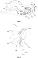
FIG. 1 is a schematic diagram of one embodiment of a spray washer of the present application; -
FIG. 2 is a partially enlarged view of a part A inFIG. 1 ; -
FIG. 3 is a schematic diagram of another embodiment of a spray washer of the present application; -
FIG. 4 is a schematic diagram of still another embodiment of a spray washer of the present application; -
FIG. 5 is a schematic diagram of one embodiment of an arrangement of a driven gear and a first transmission wheel of a spray washer of the present application; -
FIG. 6 is a schematic diagram of another embodiment of an arrangement of a driven gear and a first transmission wheel of a spray washer of the present application; -
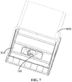
FIG. 7 is a schematic diagram of one embodiment of a dish-washing machine of the present application. - EXPLANATION OF REFERENCE NUMERAL:
TABLE 1 Reference numerals Name Reference numerals Name 100 spraying pipe 110 water inlet end 120 driving end 200 driving mechanism 300 transmission mechanism 310 driving gear 320 driven gear 110 water pump 510 water feeding pipe 400 water distributing pipe 530 reinforcing plate 520 first transmission wheel 620 first linkage 610 second transmission wheel 720 second linkage 710 - The realizing of the aim, functional characteristics and advantages of the present application are further described in detail with reference to the accompanying drawings and the embodiments.
- The technical solutions in embodiments of the application are clearly and fully described below with reference to the accompanying drawings in the embodiments of the application. Apparently, the described embodiments are merely some of the embodiments of the application, but not all the embodiments. Based on the embodiments of the application, all other embodiments obtained by a person of ordinary skill in the art without involving an inventive effort shall fall within the scope of protection of the application.
- It should be understand that, all directional indications (such as "upper", "lower", "left", "right", "front", "back" ...) in the embodiments of the present application are only used to explain the relative positional relationship, motion, and the like, between components in a certain posture. If the particular posture changes, the directional indication changes accordingly.
- In addition, if there are descriptions of "first" and "second" in the embodiments of the present application, the descriptions of "first" and "second" are used for descriptive purposes only and cannot be appreciated as indicating or implying their relative importance or implicitly indicating the number of indicated technical features. Thus, features defining "first" and "second" may explicitly or implicitly include at least one such feature. In addition, the technical solutions between the various embodiments may be combined with each other, but must be based on what one of ordinary skill in the art can achieve. When the combination of technical solutions is contradictory or impossible to achieve, it should be considered that the combination of such technical solutions does not exist and is not within the protection scope required by the present application.
- The present application mainly provides a spray washer, which is mainly applied to a dish-washing machine, so as to increase the utilization of water and the tableware cleaning efficiency of the dish-washing machine.
- The specific structure of the spray washer will be mainly described below.
- Referring to
FIG. 1 to FIG. 7 , in an embodiment of the present application , the spray washer includes: - at least one
spraying pipe 100, the sprayingpipe 100 being provided with at least one water injection nozzle; - a transmission mechanism including a
driving gear 310 and a drivengear 320 meshing with thedriving gear 310, the drivengear 320 being connected to the sprayingpipe 100 to drive the sprayingpipe 100 into rotation; and - a
driving mechanism 200 connected to thedriving gear 310 to drive thedriving gear 310 into rotation. - Specifically, in this embodiment, the spraying
pipe 100 is configured as a columnar pipe. The spraying pipe includes awater inlet end 110 and adriving end 120. That is, the water inlet structure of the sprayingpipe 100 is provided at one end of the sprayingpipe 100 and the driving structure of the sprayingpipe 100 is provided at the other end of the sprayingpipe 100, so that the driving structure and the water inlet structure do not interfere with each other. Of course, in some embodiments, in order to save space, the driving structure and the water inlet structure may also be provided at the same end of the sprayingpipe 100. The drivingend 120 of the sprayingpipe 100 is closed, and the water is discharged from the water injection nozzle after the water enters from thewater inlet end 110. The water injection nozzle is provided on the pipe wall of the sprayingpipe 100, so that the water flow may be directly sprayed from the water injection nozzle. Optionally, a sprinkler may also be installed in the water injection nozzle, so that the water may be sprayed from the sprinkler. - The driven
gear 320 may be directly provided around the drivingend 120. Of course, in some embodiments, a driven shaft can be provided on the driving end, and the drivengear 320 is provided around the driven shaft. The axis of rotation of the drivengear 320 is collinear with the axial axis of the sprayingpipe 100. Thedriving gear 310 meshes with the drivengear 320. There may be a plurality of positions of the driving gear with respect to the drivengear 320, such as, above, below, at the left side, or at the right side. The position that the driving gear is located below the drivengear 320 is taken as an example. Taking an upward spraying direction as an example, thedriving gear 310 is arranged below the driven gear so as to avoid affecting the cleaning of the tableware. Herein, thedriving gear 310 and the drivengear 320 are both spur gears. - There are many forms of driving structures, such as motors, impellers, fuel engines, etc. The
driving mechanism 200 has a driving shaft. The driving shaft is directly inserted into thedriving gear 310, or connected to thedriving gear 310 after being decelerated by thetransmission structure 300. Thedriving gear 310 rotates through the driving shaft as a rotating shaft. Thedriving mechanism 200 takes a driving motor as an example, thedriving gear 310 is fixedly connected to the rotating shaft of the driving motor. - In this embodiment, the driving force of the
driving mechanism 200 is transmitted to the sprayingpipe 100 through thedriving gear 310 and the drivengear 320, so that the sprayingpipe 100 rotates along an axial axis thereof, and water is sprayed from the water injection nozzle on the sprayingpipe 100. During the rotation of the sprayingpipe 100, a spray washing area is formed. Since the sprayingpipe 100 is driven by a gear structure, both the rotation of the sprayingpipe 100 and the transmission of power are very stable and reliable. Meanwhile, the rotation angle of the sprayingpipe 100 can be accurately controlled, so as to control the change of the spray washing area, so that the spray washer can accurately control the spraying area, which facilitates improving the accuracy of the spray washer for spray washing the tableware, and increasing the utilization of water and cleaning efficiency. - It should be noted that, in order to ensure the range of the water feeding area, the rotation angle α of the spraying
pipe 100 is from 100° to 150°, taking from 120° to 140° as an example. By setting the rotation angle of the sprayingpipe 100 as a range from 100° to 150°, it can avoid that if the angle is too large, the spraying pressure is not enough to clean; if the angle is too small, the area covered by the sprayingpipe 100 is too small to cover the entire area required for cleaning. - In order to improve the driving efficiency of the driving structure, the spray washer includes a plurality of spraying
pipes 100. The spray washer further includes afirst transmission wheel 610 and afirst linkage 620. One end of one of the sprayingpipes 100 is connected to thefirst transmission wheel 610, and the other end of the spraying pipe is in communication with a water source. One end of thefirst linkage 620 is hinged to the drivengear 320, and the other end of the first linkage is hinged to thefirst transmission wheel 610, to drive the sprayingpipe 100 and the first transmission wheel into rotation with rotation of the drivengear 320. - In this embodiment, the spraying
pipes 100 may be positioned at the front side, the rear side or on the top of the sprayingpipe 100 connected to the drivengear 320. In some embodiments, the spray washer includes a plurality offirst linkages 620 and a plurality offirst transmission wheels 610 connected to thefirst linkages 620. In this case, one drivengear 320 may simultaneously drive the plurality offirst transmission wheel 610, to simultaneously drive the plurality of sprayingpipes 100. One first transmission linkage and onefirst transmission wheel 610 are described in detail below. - One end of the
first linkage 620 is hinged to the drivengear 320, so that thefirst linkage 620 rotates with the rotation of the drivengear 320. The other end of thefirst linkage 620 is hinged to thefirst transmission wheel 610, so that thefirst linkage 620 transmits the rotation displacement of the drivengear 320 to thefirst transmission wheel 610, thefirst transmission wheel 610 converts the displacement of thefirst linkage 620 into the rotation displacement, and finally transmits the rotation displacement to the sprayingpipes 100. As a result, the sprayingpipes 100 rotate with rotation of the drivengear 320. - In some embodiments, in order to better drive the spraying
pipes 100, one of the sprayingpipes 100 is connected to a middle portion of thefirst transmission wheel 610. One end of thefirst linkage 620 is connected to an upper portion or a lower portion of thefirst transmission wheel 610, and the other end of the first linkage is connected to an upper portion or a lower portion of the drivengear 320. Herein, the connection between the sprayingpipe 100 and thefirst transmission wheel 610 is similar to the connection between the drivengear 320 and the sprayingpipe 100. The axis of rotation of the first transmission wheel is collinear with the axis of rotation of the sprayingpipe 100. One end of thefirst linkage 620 is hinged to the top of thefirst transmission wheel 610, and the other end of the first linkage is hinged to the top of the drivengear 320. In this case, the rotation direction of thefirst transmission wheel 610 is the same as the rotation direction of the drivengear 320. When one end of thefirst linkage 620 is hinged to the bottom of thefirst transmission wheel 610, and the other end of the first linkage is hinged to the top of the drivengear 320, the rotation direction of thefirst transmission wheel 610 is opposite to the rotation direction of the drivengear 320. - In order to further increase the driving efficiency of the driving mechanism, the spray washer further includes a
second transmission wheel 710 and asecond linkage 720. One end of one of the sprayingpipes 100 is connected to thesecond transmission wheel 720, and the other end of the spraying pipe is in communication with the water source. One end of thesecond linkage 720 is hinged to thefirst transmission wheel 610, and the other end of the second linkage is hinged to thesecond transmission wheel 710, to drive the sprayingpipe 100 and the second transmission wheel into rotation with the rotation of the first transmission wheel. - In this embodiment, the
second transmission wheel 710 is located on the top of thefirst transmission wheel 610, or at a side of the first transmission wheel away from the drivengear 320. The spray washer includes a plurality ofsecond transmission wheels 710 and a plurality ofsecond linkages 720. In this case, onefirst transmission wheel 610 may simultaneously drive the plurality ofsecond transmission wheels 710. One second transmission linkage and onesecond transmission wheel 710 are described in detail below. - One end of the
second linkage 720 is hinged to thefirst transmission wheel 610, so that thesecond linkage 720 rotates with the rotation of thefirst transmission wheel 610. The other end of thesecond linkage 720 is hinged to thesecond transmission wheel 710, so that thesecond linkage 720 transmits the rotation displacement of thefirst transmission wheel 610 to thesecond transmission wheel 710, thesecond transmission wheel 710 converts the displacement of thesecond linkage 720 into the rotation displacement, and finally transmits the rotation displacement to the sprayingpipes 100. As a result, the sprayingpipes 100 rotate with rotation of thefirst transmission wheel 610. - In some embodiments, in order to better drive the spraying
pipes 100, the sprayingpipe 100 is connected to a middle portion of thesecond transmission wheel 710. One end of thesecond linkage 720 is connected to an upper portion or a lower portion of thefirst transmission wheel 610, and the other end of the second linkage is connected to an upper portion or a lower portion of the second transmission wheel. - Herein, the connection between the spraying
pipe 100 and thesecond transmission wheel 710 is similar to the connection between thefirst transmission wheel 610 and the sprayingpipe 100. The axis of rotation of thesecond transmission wheel 710 is collinear with the axis of rotation of the sprayingpipe 100. One end of thesecond linkage 720 is hinged to the top of thesecond transmission wheel 710, and the other end of the second linkage is hinged to the top of thefirst transmission wheel 610. In this case, the rotation direction of thesecond transmission wheel 710 is the same as the rotation direction of thefirst transmission wheel 610. When one end of thesecond linkage 720 is hinged to the bottom of thesecond transmission wheel 710, and the other end of the second linkage is hinged to the top of thefirst transmission wheel 610, the rotation direction of thesecond transmission wheel 710 is opposite to the rotation direction of thefirst transmission wheel 610. - In order to supply sufficient water to the spraying
pipes 100, the spray washer includes a water supply assembly. The water supply assembly includes awater pump 400, awater feeding pipe 510 and a plurality ofwater distributing pipes 520. One end of thewater feeding pipe 510 is in communication with thewater pump 400, and the other end of the water feeding pipe is in communication withwater distributing pipes 520. One end of eachwater distributing pipe 520 away from thewater feeding pipe 510 is in communication with one of the sprayingpipes 100. One end of thewater feeding pipe 510 is in communication with thewater pump 400, and another end of the water feeding pipe is in communication with thewater distributing pipes 520. Thewater pump 400 pumps water from the water source to thewater feeding pipe 510, and then thewater feeding pipe 510 delivers water to thewater distributing pipes 520. One end of eachwater distributing pipe 520 away from thewater feeding pipe 510 is in communication with one of the sprayingpipes 100. There are many ways of communication, such as surrounding, adapting through adapters, etc. - Herein, the water supply assembly is located below the spraying
pipes 100, and eachwater distributing pipe 520 is arranged around thewater feeding pipe 510 after being bent. When the sprayingpipes 100 spray water upwardly, the water supply assembly below does not affect the spray washing of the sprayingpipes 100, which ensures the effect of spray washing while fully utilizing the space. - In some embodiments, in order to improve the installation stability of the water feeding assembly and reduce the vibration noise, the spray washer further includes a reinforcing
plate 530. The reinforcingplate 530 is connected to thewater distributing pipes 520 along an arrangement direction of thewater distributing pipes 520, and is provided with a fixing portion for fixing the reinforcingplate 530. The reinforcingplate 530 is fixedly connected to the inner container, so that the reinforcingplate 530 not only strengthens the strength and stability of thewater distributing pipes 520, but also prevents thewater distributing pipes 520 from swinging and vibrating greatly due to the impact of water flow by fixing thewater distributing pipes 520, thereby effectively reducing the noise generated by the swinging and vibrating of thewater distributing pipes 520. - The present application further provides a dish-washing machine. The dish-washing machine includes an inner container and a spray washer. The specific structure of the spray washer refers to the above embodiments. Since the dish-washing machine adopts all the technical solutions of the above embodiments, the dish-washing machine at least has all the beneficial effects brought by the technical solutions of the above embodiments, which is not repeated here. Herein, the inner container has a receiving chamber, within which the spray washer is arranged.
- In order to improve the spray washing efficiency and effect of the spraying
pipes 100, the dish-washing machine includes a bowl basket arranged within the inner container. Each sprayingpipe 100 is provided with a plurality of water injection nozzles, which are arranged along a length direction of each sprayingpipe 100 corresponding to a position of the bowl basket. The water injection nozzles are arranged corresponding to the bowl basket, so that the water flow sprayed from the water injection nozzles can be accurately sprayed onto the bowl basket, so as to improve the efficiency of cleaning the tableware in the bowl basket. - The description aforementioned is only the preferred embodiment of the present application and is not intended to limit the scope of the present application. Any equivalent structural modification made by using the description and drawings of the present application or direct/indirect application in other related technical fields under the concept of the present application shall be included in the protection scope of the present application.
Claims (11)
- A spray washer, comprising:at least one spraying pipe provided with at least one water injection nozzle;a transmission mechanism comprising a driving gear and a driven gear meshing with the driving gear, the driven gear being connected to the spraying pipe to drive the spraying pipe into rotation; anda driving mechanism connected to the driving gear to drive the driving gear into rotation.
- The spray washer of claim 1, wherein the spray washer comprises a plurality of spraying pipes, and further comprises a first transmission wheel and a first linkage;wherein one end of one of the spraying pipes is connected to the first transmission wheel, and the other end of the spraying pipe is in communication with a water source; andwherein one end of the first linkage is hinged to the driven gear, and the other end of the first linkage is hinged to the first transmission wheel, to drive the spraying pipe and the first transmission wheel into rotation with rotation of the driven gear.
- The spray washer of claim 2, wherein the spraying pipe is connected to a middle portion of the first transmission wheel; and
wherein one end of the first linkage is connected to an upper portion or a lower portion of the first transmission wheel, and the other end of the first linkage is connected to an upper portion or a lower portion of the driven gear. - The spray washer of claim 2, wherein the spray washer further comprises a second transmission wheel and a second linkage;wherein one end of one of the spraying pipes is connected to the second transmission wheel, and the other end of the spraying pipe is in communication with the water source; andwherein one end of the second linkage is hinged to the first transmission wheel, and the other end of the second linkage is hinged to the second transmission wheel, to drive the spraying pipe and the second transmission wheel into rotation with the rotation of the first transmission wheel.
- The spray washer of claim 4, wherein the spraying pipe is connected to a middle portion of the second transmission wheel; and
wherein said one end of the second linkage is connected to an upper portion or a lower portion of the first transmission wheel, and the other end of the second linkage is connected to an upper portion or a lower portion of the second transmission wheel. - The spray washer of any one of claims 1 to 5, wherein the spray washer comprises a water supply assembly, the water supply assembly comprising a water pump, a water feeding pipe and a plurality of water distributing pipes;wherein one end of the water feeding pipe is in communication with the water pump, and the other end of the water feeding pipe is in communication with the water distributing pipes; andwherein one end of each water distributing pipe away from the water feeding pipe is in communication with one of the spraying pipes.
- The spray washer of claim 6, wherein the water supply assembly is located below the spraying pipes, and each water distributing pipe is arranged around the water feeding pipe after being bent.
- The spray washer of claim 6, wherein the spray washer further comprises a reinforcing plate, wherein the reinforcing plate is connected to the water distributing pipes along an arrangement direction of the water distributing pipes, and the reinforcing plate is provided with a fixing portion for fixing the reinforcing plate.
- The spray washer of any one of claims 1 to 5, wherein a rotation angle between an initial rotation position and an end rotation position of each spraying pipe is no less than100° and no more than 150°.
- A dish-washing machine, comprising:an inner container provided with a receiving chamber; anda spray washer of any one of claims 1 to 9, wherein the spray washer is arranged within the receiving chamber.
- The dish-washing machine of claim 10, wherein the dish-washing machine comprises a bowl basket arranged within the inner container; and
wherein each spraying pipe is provided with a plurality of water injection nozzles, which are arranged along a length direction of each spraying pipe corresponding to a position of the bowl basket.
Applications Claiming Priority (2)
| Application Number | Priority Date | Filing Date | Title |
|---|---|---|---|
| CN201811207855.6A CN111053513B (en) | 2018-10-16 | 2018-10-16 | Spray-wash units and dishwashers |
| PCT/CN2018/122630 WO2020077816A1 (en) | 2018-10-16 | 2018-12-21 | Spraying apparatus and dish-washing machine |
Publications (3)
| Publication Number | Publication Date |
|---|---|
| EP3847943A1 true EP3847943A1 (en) | 2021-07-14 |
| EP3847943A4 EP3847943A4 (en) | 2021-11-03 |
| EP3847943B1 EP3847943B1 (en) | 2024-03-13 |
Family
ID=70284181
Family Applications (1)
| Application Number | Title | Priority Date | Filing Date |
|---|---|---|---|
| EP18936967.1A Active EP3847943B1 (en) | 2018-10-16 | 2018-12-21 | Spraying apparatus and dish-washing machine |
Country Status (6)
| Country | Link |
|---|---|
| US (1) | US12070172B2 (en) |
| EP (1) | EP3847943B1 (en) |
| JP (1) | JP7525233B2 (en) |
| KR (1) | KR102476646B1 (en) |
| CN (1) | CN111053513B (en) |
| WO (1) | WO2020077816A1 (en) |
Cited By (1)
| Publication number | Priority date | Publication date | Assignee | Title |
|---|---|---|---|---|
| EP3868278A4 (en) * | 2018-10-16 | 2021-12-22 | Foshan Shunde Midea Washing Appliances Manufacturing Co., Ltd. | SPRAYING EQUIPMENT AND ASSOCIATED CONTROL PROCESS AND DISHWASHER |
Families Citing this family (1)
| Publication number | Priority date | Publication date | Assignee | Title |
|---|---|---|---|---|
| CN114098578A (en) * | 2020-09-01 | 2022-03-01 | 佛山市顺德区美的洗涤电器制造有限公司 | Spray rod driving device of dish washing machine, spray rod assembly of dish washing machine and dish washing machine |
Family Cites Families (31)
| Publication number | Priority date | Publication date | Assignee | Title |
|---|---|---|---|---|
| JPS60109568U (en) * | 1983-12-28 | 1985-07-25 | 伊東 璋 | Container cleaning machine |
| JPH0317821Y2 (en) * | 1985-08-12 | 1991-04-15 | ||
| JPH0632764B2 (en) * | 1988-05-10 | 1994-05-02 | 日本碍子株式会社 | Automatic rainfall nozzle and water injection method using the same |
| JPH0229658U (en) | 1988-08-10 | 1990-02-26 | ||
| JPH02220625A (en) | 1989-02-23 | 1990-09-03 | Fujitsu General Ltd | dishwasher |
| JP2573648Y2 (en) | 1990-10-19 | 1998-06-04 | 中部電力株式会社 | Dishwasher |
| KR940007664Y1 (en) * | 1992-10-16 | 1994-10-22 | 이헌조 | Washing water spray device of dishwasher |
| US5415350A (en) * | 1993-03-06 | 1995-05-16 | Goldstar Co., Ltd. | Water spraying device for tableware washer |
| CN2263147Y (en) * | 1995-06-28 | 1997-09-24 | 和成欣业股份有限公司 | Water spray structure of toilet seat |
| JPH0910159A (en) * | 1995-06-30 | 1997-01-14 | Mitsubishi Electric Corp | Dishwasher |
| CN101301187A (en) | 2007-05-08 | 2008-11-12 | 施兆登 | Full-automatic swiftly moving and spraying type bowl washing machine |
| KR20100075220A (en) * | 2008-12-24 | 2010-07-02 | 주식회사 포스코 | Rotary type water spray apparatus for cooling hot slab |
| KR101130787B1 (en) * | 2009-06-23 | 2012-03-28 | 송세진 | Sink attachment type dish washing apparatus |
| DE102010042576A1 (en) * | 2010-10-18 | 2012-04-19 | BSH Bosch und Siemens Hausgeräte GmbH | Dishwasher with at least one spraying device |
| CN202446038U (en) * | 2012-01-04 | 2012-09-26 | 郭灵新 | Rotatable L-shaped spray pipe of dish-washing machine |
| CN103284674A (en) | 2012-02-27 | 2013-09-11 | 佛山市顺德区盛熙电器制造有限公司 | Dish-washing machine |
| KR20150009399A (en) * | 2013-07-16 | 2015-01-26 | 삼성전자주식회사 | Dish washer |
| CN204293091U (en) * | 2014-12-17 | 2015-04-29 | 张得坤 | The efficient dish-washing machine of combined multifunctional |
| CN104720711A (en) * | 2015-02-13 | 2015-06-24 | 佛山市南海康明车业有限公司 | Dish washing machine with spray-wash pipes capable of rotating around self axes |
| CN104814710B (en) * | 2015-05-26 | 2018-02-06 | 佛山市顺德区美的洗涤电器制造有限公司 | Spray arm component and there is its dish-washing machine |
| KR102387525B1 (en) * | 2015-06-18 | 2022-04-19 | 주식회사 케이씨텍 | Oscillation nozzle apparatus |
| US10064536B2 (en) * | 2016-03-21 | 2018-09-04 | Whirlpool Corporation | Dishwasher with hydraulically powered wash system |
| CN105942951B (en) * | 2016-04-29 | 2019-04-02 | 佛山市顺德区美的洗涤电器制造有限公司 | Spray arm assembly for dishwasher and dishwasher having the same |
| CN205924989U (en) * | 2016-06-14 | 2017-02-08 | 杜远群 | Fire car toy warp |
| CN106073675B (en) * | 2016-08-16 | 2019-02-15 | 广东省智能制造研究所 | Dishwasher and control method thereof |
| CN206675491U (en) * | 2016-08-16 | 2017-11-28 | 广东省自动化研究所 | A kind of Household bowl washing device |
| CN106419794A (en) * | 2016-10-20 | 2017-02-22 | 珠海格力电器股份有限公司 | Dish washer spray set and dish washer |
| CN108078525B (en) * | 2017-07-31 | 2023-11-17 | 宁波方太厨具有限公司 | Dish washer |
| CN107597769A (en) * | 2017-09-30 | 2018-01-19 | 宁波市镇海秀洋广告装饰有限公司 | A kind of chemical experiment multiple cups while cleaning device |
| CN112543612B (en) * | 2018-09-12 | 2023-07-21 | 佛山市顺德区美的洗涤电器制造有限公司 | Dishwasher and method of operating same |
| CN209122118U (en) * | 2018-10-16 | 2019-07-19 | 广东美的白色家电技术创新中心有限公司 | Jetter and dish-washing machine |
-
2018
- 2018-10-16 CN CN201811207855.6A patent/CN111053513B/en active Active
- 2018-12-21 KR KR1020217010160A patent/KR102476646B1/en active Active
- 2018-12-21 JP JP2021543552A patent/JP7525233B2/en active Active
- 2018-12-21 EP EP18936967.1A patent/EP3847943B1/en active Active
- 2018-12-21 US US17/285,083 patent/US12070172B2/en active Active
- 2018-12-21 WO PCT/CN2018/122630 patent/WO2020077816A1/en not_active Ceased
Cited By (1)
| Publication number | Priority date | Publication date | Assignee | Title |
|---|---|---|---|---|
| EP3868278A4 (en) * | 2018-10-16 | 2021-12-22 | Foshan Shunde Midea Washing Appliances Manufacturing Co., Ltd. | SPRAYING EQUIPMENT AND ASSOCIATED CONTROL PROCESS AND DISHWASHER |
Also Published As
| Publication number | Publication date |
|---|---|
| US20220233051A1 (en) | 2022-07-28 |
| CN111053513A (en) | 2020-04-24 |
| WO2020077816A1 (en) | 2020-04-23 |
| EP3847943B1 (en) | 2024-03-13 |
| JP7525233B2 (en) | 2024-07-30 |
| EP3847943A4 (en) | 2021-11-03 |
| KR102476646B1 (en) | 2022-12-09 |
| JP2022508579A (en) | 2022-01-19 |
| CN111053513B (en) | 2024-06-21 |
| US12070172B2 (en) | 2024-08-27 |
| KR20210049169A (en) | 2021-05-04 |
Similar Documents
| Publication | Publication Date | Title |
|---|---|---|
| EP3287062B1 (en) | Spraying arm assembly for dishwasher and dishwasher having same | |
| CN104757921A (en) | Gushing arm component used for dish washing machine and dish washing machine provided with the same | |
| EP3847943A1 (en) | Spraying apparatus and dish-washing machine | |
| CN104644097B (en) | Spray arm component and dish-washing machine for dish-washing machine | |
| KR101300919B1 (en) | Dish washer | |
| EP3266361B1 (en) | Spray arm assembly for dishwasher, and dishwasher | |
| KR20040046943A (en) | Nozzle of dish washer | |
| KR101876376B1 (en) | Dish washing machine | |
| CN209122118U (en) | Jetter and dish-washing machine | |
| CN210545823U (en) | Anticorrosive paint spraying device for water pump processing | |
| CN211381074U (en) | Building door and window that can spray water clearance | |
| CN109620087A (en) | A kind of spray thrower and dish-washing machine of dish-washing machine | |
| CN208346508U (en) | A kind of automatic dissolving and sparger of the cleaning solution for washing machine | |
| CN209122119U (en) | Hydro-peening module and dish-washing machine | |
| CN204427969U (en) | For spray arm assembly and the dish-washing machine of dish-washing machine | |
| CN209613662U (en) | A kind of spray equipment and cleaning machine | |
| CN222751945U (en) | Electric cleaning brush | |
| KR200300795Y1 (en) | a water sprayer for dishwasher | |
| CN216062554U (en) | Automatic long-range fog sprayer that penetrates of chain dirt that presses down | |
| CN220572102U (en) | Fan-shaped spraying structure of glass cleaning machine | |
| CN210337875U (en) | A wheel washer cleaning mechanism for a construction site | |
| CN114342782A (en) | Ecological resource circulation's gardens water supply irrigation equipment | |
| CN113699007A (en) | Water metering mechanism | |
| CN1115133C (en) | Tableware cleaner | |
| KR930006002B1 (en) | Eccentric Rotating Device of Dishwasher Nozzle |
Legal Events
| Date | Code | Title | Description |
|---|---|---|---|
| STAA | Information on the status of an ep patent application or granted ep patent |
Free format text: STATUS: THE INTERNATIONAL PUBLICATION HAS BEEN MADE |
|
| PUAI | Public reference made under article 153(3) epc to a published international application that has entered the european phase |
Free format text: ORIGINAL CODE: 0009012 |
|
| STAA | Information on the status of an ep patent application or granted ep patent |
Free format text: STATUS: REQUEST FOR EXAMINATION WAS MADE |
|
| 17P | Request for examination filed |
Effective date: 20210408 |
|
| AK | Designated contracting states |
Kind code of ref document: A1 Designated state(s): AL AT BE BG CH CY CZ DE DK EE ES FI FR GB GR HR HU IE IS IT LI LT LU LV MC MK MT NL NO PL PT RO RS SE SI SK SM TR |
|
| A4 | Supplementary search report drawn up and despatched |
Effective date: 20211005 |
|
| RIC1 | Information provided on ipc code assigned before grant |
Ipc: A47L 15/42 20060101ALI20210929BHEP Ipc: A47L 15/22 20060101AFI20210929BHEP |
|
| DAV | Request for validation of the european patent (deleted) | ||
| DAX | Request for extension of the european patent (deleted) | ||
| GRAP | Despatch of communication of intention to grant a patent |
Free format text: ORIGINAL CODE: EPIDOSNIGR1 |
|
| STAA | Information on the status of an ep patent application or granted ep patent |
Free format text: STATUS: GRANT OF PATENT IS INTENDED |
|
| INTG | Intention to grant announced |
Effective date: 20231117 |
|
| GRAS | Grant fee paid |
Free format text: ORIGINAL CODE: EPIDOSNIGR3 |
|
| GRAA | (expected) grant |
Free format text: ORIGINAL CODE: 0009210 |
|
| STAA | Information on the status of an ep patent application or granted ep patent |
Free format text: STATUS: THE PATENT HAS BEEN GRANTED |
|
| AK | Designated contracting states |
Kind code of ref document: B1 Designated state(s): AL AT BE BG CH CY CZ DE DK EE ES FI FR GB GR HR HU IE IS IT LI LT LU LV MC MK MT NL NO PL PT RO RS SE SI SK SM TR |
|
| REG | Reference to a national code |
Ref country code: GB Ref legal event code: FG4D |
|
| REG | Reference to a national code |
Ref country code: CH Ref legal event code: EP |
|
| REG | Reference to a national code |
Ref country code: DE Ref legal event code: R096 Ref document number: 602018066748 Country of ref document: DE |
|
| REG | Reference to a national code |
Ref country code: IE Ref legal event code: FG4D |
|
| P01 | Opt-out of the competence of the unified patent court (upc) registered |
Effective date: 20240520 |
|
| PG25 | Lapsed in a contracting state [announced via postgrant information from national office to epo] |
Ref country code: LT Free format text: LAPSE BECAUSE OF FAILURE TO SUBMIT A TRANSLATION OF THE DESCRIPTION OR TO PAY THE FEE WITHIN THE PRESCRIBED TIME-LIMIT Effective date: 20240313 |
|
| REG | Reference to a national code |
Ref country code: LT Ref legal event code: MG9D |
|
| PG25 | Lapsed in a contracting state [announced via postgrant information from national office to epo] |
Ref country code: GR Free format text: LAPSE BECAUSE OF FAILURE TO SUBMIT A TRANSLATION OF THE DESCRIPTION OR TO PAY THE FEE WITHIN THE PRESCRIBED TIME-LIMIT Effective date: 20240614 |
|
| REG | Reference to a national code |
Ref country code: NL Ref legal event code: MP Effective date: 20240313 |
|
| PG25 | Lapsed in a contracting state [announced via postgrant information from national office to epo] |
Ref country code: HR Free format text: LAPSE BECAUSE OF FAILURE TO SUBMIT A TRANSLATION OF THE DESCRIPTION OR TO PAY THE FEE WITHIN THE PRESCRIBED TIME-LIMIT Effective date: 20240313 Ref country code: RS Free format text: LAPSE BECAUSE OF FAILURE TO SUBMIT A TRANSLATION OF THE DESCRIPTION OR TO PAY THE FEE WITHIN THE PRESCRIBED TIME-LIMIT Effective date: 20240613 |
|
| PG25 | Lapsed in a contracting state [announced via postgrant information from national office to epo] |
Ref country code: ES Free format text: LAPSE BECAUSE OF FAILURE TO SUBMIT A TRANSLATION OF THE DESCRIPTION OR TO PAY THE FEE WITHIN THE PRESCRIBED TIME-LIMIT Effective date: 20240313 |
|
| PG25 | Lapsed in a contracting state [announced via postgrant information from national office to epo] |
Ref country code: RS Free format text: LAPSE BECAUSE OF FAILURE TO SUBMIT A TRANSLATION OF THE DESCRIPTION OR TO PAY THE FEE WITHIN THE PRESCRIBED TIME-LIMIT Effective date: 20240613 Ref country code: NO Free format text: LAPSE BECAUSE OF FAILURE TO SUBMIT A TRANSLATION OF THE DESCRIPTION OR TO PAY THE FEE WITHIN THE PRESCRIBED TIME-LIMIT Effective date: 20240613 Ref country code: LT Free format text: LAPSE BECAUSE OF FAILURE TO SUBMIT A TRANSLATION OF THE DESCRIPTION OR TO PAY THE FEE WITHIN THE PRESCRIBED TIME-LIMIT Effective date: 20240313 Ref country code: HR Free format text: LAPSE BECAUSE OF FAILURE TO SUBMIT A TRANSLATION OF THE DESCRIPTION OR TO PAY THE FEE WITHIN THE PRESCRIBED TIME-LIMIT Effective date: 20240313 Ref country code: GR Free format text: LAPSE BECAUSE OF FAILURE TO SUBMIT A TRANSLATION OF THE DESCRIPTION OR TO PAY THE FEE WITHIN THE PRESCRIBED TIME-LIMIT Effective date: 20240614 Ref country code: FI Free format text: LAPSE BECAUSE OF FAILURE TO SUBMIT A TRANSLATION OF THE DESCRIPTION OR TO PAY THE FEE WITHIN THE PRESCRIBED TIME-LIMIT Effective date: 20240313 Ref country code: ES Free format text: LAPSE BECAUSE OF FAILURE TO SUBMIT A TRANSLATION OF THE DESCRIPTION OR TO PAY THE FEE WITHIN THE PRESCRIBED TIME-LIMIT Effective date: 20240313 Ref country code: BG Free format text: LAPSE BECAUSE OF FAILURE TO SUBMIT A TRANSLATION OF THE DESCRIPTION OR TO PAY THE FEE WITHIN THE PRESCRIBED TIME-LIMIT Effective date: 20240313 |
|
| REG | Reference to a national code |
Ref country code: AT Ref legal event code: MK05 Ref document number: 1664923 Country of ref document: AT Kind code of ref document: T Effective date: 20240313 |
|
| PG25 | Lapsed in a contracting state [announced via postgrant information from national office to epo] |
Ref country code: SE Free format text: LAPSE BECAUSE OF FAILURE TO SUBMIT A TRANSLATION OF THE DESCRIPTION OR TO PAY THE FEE WITHIN THE PRESCRIBED TIME-LIMIT Effective date: 20240313 Ref country code: LV Free format text: LAPSE BECAUSE OF FAILURE TO SUBMIT A TRANSLATION OF THE DESCRIPTION OR TO PAY THE FEE WITHIN THE PRESCRIBED TIME-LIMIT Effective date: 20240313 |
|
| PG25 | Lapsed in a contracting state [announced via postgrant information from national office to epo] |
Ref country code: NL Free format text: LAPSE BECAUSE OF FAILURE TO SUBMIT A TRANSLATION OF THE DESCRIPTION OR TO PAY THE FEE WITHIN THE PRESCRIBED TIME-LIMIT Effective date: 20240313 |
|
| PG25 | Lapsed in a contracting state [announced via postgrant information from national office to epo] |
Ref country code: NL Free format text: LAPSE BECAUSE OF FAILURE TO SUBMIT A TRANSLATION OF THE DESCRIPTION OR TO PAY THE FEE WITHIN THE PRESCRIBED TIME-LIMIT Effective date: 20240313 |
|
| PG25 | Lapsed in a contracting state [announced via postgrant information from national office to epo] |
Ref country code: IS Free format text: LAPSE BECAUSE OF FAILURE TO SUBMIT A TRANSLATION OF THE DESCRIPTION OR TO PAY THE FEE WITHIN THE PRESCRIBED TIME-LIMIT Effective date: 20240713 |
|
| PG25 | Lapsed in a contracting state [announced via postgrant information from national office to epo] |
Ref country code: SM Free format text: LAPSE BECAUSE OF FAILURE TO SUBMIT A TRANSLATION OF THE DESCRIPTION OR TO PAY THE FEE WITHIN THE PRESCRIBED TIME-LIMIT Effective date: 20240313 Ref country code: PT Free format text: LAPSE BECAUSE OF FAILURE TO SUBMIT A TRANSLATION OF THE DESCRIPTION OR TO PAY THE FEE WITHIN THE PRESCRIBED TIME-LIMIT Effective date: 20240715 |
|
| PG25 | Lapsed in a contracting state [announced via postgrant information from national office to epo] |
Ref country code: EE Free format text: LAPSE BECAUSE OF FAILURE TO SUBMIT A TRANSLATION OF THE DESCRIPTION OR TO PAY THE FEE WITHIN THE PRESCRIBED TIME-LIMIT Effective date: 20240313 Ref country code: CZ Free format text: LAPSE BECAUSE OF FAILURE TO SUBMIT A TRANSLATION OF THE DESCRIPTION OR TO PAY THE FEE WITHIN THE PRESCRIBED TIME-LIMIT Effective date: 20240313 |
|
| PG25 | Lapsed in a contracting state [announced via postgrant information from national office to epo] |
Ref country code: AT Free format text: LAPSE BECAUSE OF FAILURE TO SUBMIT A TRANSLATION OF THE DESCRIPTION OR TO PAY THE FEE WITHIN THE PRESCRIBED TIME-LIMIT Effective date: 20240313 |
|
| PG25 | Lapsed in a contracting state [announced via postgrant information from national office to epo] |
Ref country code: PL Free format text: LAPSE BECAUSE OF FAILURE TO SUBMIT A TRANSLATION OF THE DESCRIPTION OR TO PAY THE FEE WITHIN THE PRESCRIBED TIME-LIMIT Effective date: 20240313 |
|
| PG25 | Lapsed in a contracting state [announced via postgrant information from national office to epo] |
Ref country code: SK Free format text: LAPSE BECAUSE OF FAILURE TO SUBMIT A TRANSLATION OF THE DESCRIPTION OR TO PAY THE FEE WITHIN THE PRESCRIBED TIME-LIMIT Effective date: 20240313 |
|
| PG25 | Lapsed in a contracting state [announced via postgrant information from national office to epo] |
Ref country code: SM Free format text: LAPSE BECAUSE OF FAILURE TO SUBMIT A TRANSLATION OF THE DESCRIPTION OR TO PAY THE FEE WITHIN THE PRESCRIBED TIME-LIMIT Effective date: 20240313 Ref country code: SK Free format text: LAPSE BECAUSE OF FAILURE TO SUBMIT A TRANSLATION OF THE DESCRIPTION OR TO PAY THE FEE WITHIN THE PRESCRIBED TIME-LIMIT Effective date: 20240313 Ref country code: RO Free format text: LAPSE BECAUSE OF FAILURE TO SUBMIT A TRANSLATION OF THE DESCRIPTION OR TO PAY THE FEE WITHIN THE PRESCRIBED TIME-LIMIT Effective date: 20240313 Ref country code: PT Free format text: LAPSE BECAUSE OF FAILURE TO SUBMIT A TRANSLATION OF THE DESCRIPTION OR TO PAY THE FEE WITHIN THE PRESCRIBED TIME-LIMIT Effective date: 20240715 Ref country code: PL Free format text: LAPSE BECAUSE OF FAILURE TO SUBMIT A TRANSLATION OF THE DESCRIPTION OR TO PAY THE FEE WITHIN THE PRESCRIBED TIME-LIMIT Effective date: 20240313 Ref country code: IS Free format text: LAPSE BECAUSE OF FAILURE TO SUBMIT A TRANSLATION OF THE DESCRIPTION OR TO PAY THE FEE WITHIN THE PRESCRIBED TIME-LIMIT Effective date: 20240713 Ref country code: EE Free format text: LAPSE BECAUSE OF FAILURE TO SUBMIT A TRANSLATION OF THE DESCRIPTION OR TO PAY THE FEE WITHIN THE PRESCRIBED TIME-LIMIT Effective date: 20240313 Ref country code: CZ Free format text: LAPSE BECAUSE OF FAILURE TO SUBMIT A TRANSLATION OF THE DESCRIPTION OR TO PAY THE FEE WITHIN THE PRESCRIBED TIME-LIMIT Effective date: 20240313 Ref country code: AT Free format text: LAPSE BECAUSE OF FAILURE TO SUBMIT A TRANSLATION OF THE DESCRIPTION OR TO PAY THE FEE WITHIN THE PRESCRIBED TIME-LIMIT Effective date: 20240313 |
|
| PG25 | Lapsed in a contracting state [announced via postgrant information from national office to epo] |
Ref country code: IT Free format text: LAPSE BECAUSE OF FAILURE TO SUBMIT A TRANSLATION OF THE DESCRIPTION OR TO PAY THE FEE WITHIN THE PRESCRIBED TIME-LIMIT Effective date: 20240313 |
|
| REG | Reference to a national code |
Ref country code: DE Ref legal event code: R097 Ref document number: 602018066748 Country of ref document: DE |
|
| PG25 | Lapsed in a contracting state [announced via postgrant information from national office to epo] |
Ref country code: IT Free format text: LAPSE BECAUSE OF FAILURE TO SUBMIT A TRANSLATION OF THE DESCRIPTION OR TO PAY THE FEE WITHIN THE PRESCRIBED TIME-LIMIT Effective date: 20240313 |
|
| PG25 | Lapsed in a contracting state [announced via postgrant information from national office to epo] |
Ref country code: DK Free format text: LAPSE BECAUSE OF FAILURE TO SUBMIT A TRANSLATION OF THE DESCRIPTION OR TO PAY THE FEE WITHIN THE PRESCRIBED TIME-LIMIT Effective date: 20240313 |
|
| PLBE | No opposition filed within time limit |
Free format text: ORIGINAL CODE: 0009261 |
|
| STAA | Information on the status of an ep patent application or granted ep patent |
Free format text: STATUS: NO OPPOSITION FILED WITHIN TIME LIMIT |
|
| PG25 | Lapsed in a contracting state [announced via postgrant information from national office to epo] |
Ref country code: DK Free format text: LAPSE BECAUSE OF FAILURE TO SUBMIT A TRANSLATION OF THE DESCRIPTION OR TO PAY THE FEE WITHIN THE PRESCRIBED TIME-LIMIT Effective date: 20240313 |
|
| 26N | No opposition filed |
Effective date: 20241216 |
|
| PG25 | Lapsed in a contracting state [announced via postgrant information from national office to epo] |
Ref country code: SI Free format text: LAPSE BECAUSE OF FAILURE TO SUBMIT A TRANSLATION OF THE DESCRIPTION OR TO PAY THE FEE WITHIN THE PRESCRIBED TIME-LIMIT Effective date: 20240313 |
|
| PG25 | Lapsed in a contracting state [announced via postgrant information from national office to epo] |
Ref country code: MC Free format text: LAPSE BECAUSE OF FAILURE TO SUBMIT A TRANSLATION OF THE DESCRIPTION OR TO PAY THE FEE WITHIN THE PRESCRIBED TIME-LIMIT Effective date: 20240313 |
|
| REG | Reference to a national code |
Ref country code: CH Ref legal event code: PL |
|
| PG25 | Lapsed in a contracting state [announced via postgrant information from national office to epo] |
Ref country code: LU Free format text: LAPSE BECAUSE OF NON-PAYMENT OF DUE FEES Effective date: 20241221 |
|
| REG | Reference to a national code |
Ref country code: BE Ref legal event code: MM Effective date: 20241231 |
|
| PG25 | Lapsed in a contracting state [announced via postgrant information from national office to epo] |
Ref country code: BE Free format text: LAPSE BECAUSE OF NON-PAYMENT OF DUE FEES Effective date: 20241231 |
|
| PG25 | Lapsed in a contracting state [announced via postgrant information from national office to epo] |
Ref country code: CH Free format text: LAPSE BECAUSE OF NON-PAYMENT OF DUE FEES Effective date: 20241231 |
|
| PG25 | Lapsed in a contracting state [announced via postgrant information from national office to epo] |
Ref country code: IE Free format text: LAPSE BECAUSE OF NON-PAYMENT OF DUE FEES Effective date: 20241221 |
|
| PGFP | Annual fee paid to national office [announced via postgrant information from national office to epo] |
Ref country code: DE Payment date: 20251212 Year of fee payment: 8 |
|
| PGFP | Annual fee paid to national office [announced via postgrant information from national office to epo] |
Ref country code: GB Payment date: 20251211 Year of fee payment: 8 |
|
| PGFP | Annual fee paid to national office [announced via postgrant information from national office to epo] |
Ref country code: FR Payment date: 20251212 Year of fee payment: 8 |