EP3847529B1 - Ereignisauslösung in phased-array-systemen - Google Patents
Ereignisauslösung in phased-array-systemen Download PDFInfo
- Publication number
- EP3847529B1 EP3847529B1 EP19769198.3A EP19769198A EP3847529B1 EP 3847529 B1 EP3847529 B1 EP 3847529B1 EP 19769198 A EP19769198 A EP 19769198A EP 3847529 B1 EP3847529 B1 EP 3847529B1
- Authority
- EP
- European Patent Office
- Prior art keywords
- point
- focus
- transducer array
- volume
- control field
- Prior art date
- Legal status (The legal status is an assumption and is not a legal conclusion. Google has not performed a legal analysis and makes no representation as to the accuracy of the status listed.)
- Active
Links
Images




Classifications
-
- G—PHYSICS
- G06—COMPUTING OR CALCULATING; COUNTING
- G06F—ELECTRIC DIGITAL DATA PROCESSING
- G06F3/00—Input arrangements for transferring data to be processed into a form capable of being handled by the computer; Output arrangements for transferring data from processing unit to output unit, e.g. interface arrangements
- G06F3/01—Input arrangements or combined input and output arrangements for interaction between user and computer
- G06F3/016—Input arrangements with force or tactile feedback as computer generated output to the user
-
- G—PHYSICS
- G10—MUSICAL INSTRUMENTS; ACOUSTICS
- G10K—SOUND-PRODUCING DEVICES; METHODS OR DEVICES FOR PROTECTING AGAINST, OR FOR DAMPING, NOISE OR OTHER ACOUSTIC WAVES IN GENERAL; ACOUSTICS NOT OTHERWISE PROVIDED FOR
- G10K11/00—Methods or devices for transmitting, conducting or directing sound in general; Methods or devices for protecting against, or for damping, noise or other acoustic waves in general
- G10K11/18—Methods or devices for transmitting, conducting or directing sound
- G10K11/26—Sound-focusing or directing, e.g. scanning
- G10K11/34—Sound-focusing or directing, e.g. scanning using electrical steering of transducer arrays, e.g. beam steering
Definitions
- the present disclosure relates generally to improved techniques for using timing techniques to improve performance of phased-array systems.
- a continuous distribution of sound energy which will be referred to as an "acoustic field" can be used for a range of applications including parametric audio, haptic feedback in mid-air and the levitation of objects.
- the acoustic field can be controlled.
- Each point can be assigned a value equating to a desired amplitude at the control point.
- a physical set of transducers can then be controlled as a phased-array system to create an acoustic field exhibiting the desired amplitude at the control points.
- timing is important, as different transducers must be supplied waves that are precisely synchronized in time. If the field is to be dynamically controlled in a way that deviates from the traditional approach of assuming a static field for all time, then the device must be aware of the time of flight necessary to effect a change in the field such that waves from each transducer reach the same point at the same time. This allows the device to create near-instantaneous changes (within a few periods of the carrier frequency) in the field. However, the computational requirements of driving the array calculations at a speed necessary to respond quickly enough to include near-instantaneous effects is prohibitive. If there were a way to include these effects without the computational cost, then this would be commercially valuable.
- haptic feedback may be created.
- These points of haptic feedback are the control points, which are created by controlling a substantially monochromatic ultrasonic acoustic field to generate this known excitation waveform at a point in space.
- the acoustic field is demodulated into either a haptic sensation experienced by the skin or an audible sound that may be experienced.
- Tracking systems are required to determine the location and orientation of body parts to determine where to place the control points to best elicit the haptic or audio desired. These tracking systems may be poorly calibrated or insufficiently precise, creating potentially large sources of error in the locations of the creation of these points.
- One method to create near-instantaneous effects as described above is to split the update process of the array state into parts that depend on different update rates.
- leveraging the physical properties of the focusing system may improve the intersection between the body part and the control point in the presence of uncertainty in the tracking system.
- a larger volume (region) of space is addressed which more certainly contains the body part participating in the interaction.
- This larger volume is then subjected to the ultrasonic radiative energy flux which encodes the properties desired for the interaction point, which may include haptic and/or audio points.
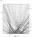
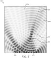
- Figures 1 , 2 , 3 , 4 , 5 and 6 are exemplary wave radiation schematics generated by a plurality of transducers.
- a way to create near-instantaneous effects as described above, is to split the update process of the array state into parts that depend on different update rates.
- the slow updates that contain individual transducer or array state data that occupy the array for a given period of time are updated through one channel, but discrete 'triggering' commands or events that occur or are applied instantly are updated through another.
- These triggering commands may be time-stamped with the time at which they are intended to be applied and priority queued on the device in a location specifically to quickly determine the next command and apply it.
- these commands may also be applied in a staggered fashion to each transducer so that the effects generated by the command reach the control point simultaneously at the instant in time specified in the time-stamp. Given that these commands are time-stamped, they may be sent to multiple devices in turn and these devices may be guaranteed to wait the appropriate amount of time before triggering the effect. Examples of such commands include but are not limited to: instantaneous change of the transducer driving signal to some preloaded state, powering the device off or down, inducing a specified phase shift at the control point, triggering an external device by driving an edge on an output pin, triggering the generation of instantaneous debugging information or responding to invalid input.
- the timing of the triggers for these commands may be offset by the time of flight required for the waves to travel and reach the point where the desired effect is to be created. Especially in the context of haptics and parametric audio, this enables the timestamp of these timed commands to be coincident with the onset of a sensory cue. Optionally, this yields synchronization of the cue to the user with an external device.
- this offset may be used ahead of time, allowing a change in the device to be specified with a known timestamp such that it is guaranteed for the waves to reach a target point at this known time. This may elicit a synchronized sensory experience linked to an external event.
- the device may use time stamping to signify that events have occurred.
- events that could trigger include but are not limited to: microphones recording a test signal, component failure or obtaining some processed information through microphones or other input.
- the areas filled with acoustic radiation energy when the transducer array is focused can be visualized analogously to an optical lens.
- the array when operating is an 'aperture' which is synthesized from the contributions from each of the transducers, this is projected through the focus when the phased array system is actively focusing. Intuitively and roughly speaking therefore, at twice the focusing distance the energy flux that was focused is now spread over an area equivalent to the array size.
- the concentration and subsequent rarefaction of the energy flux along the focusing path may be leveraged to provide a larger volume for the energy to flow through. Choosing a different part of the beam to use away from the focus is effectively equivalent to a larger focal spot. These regions of high energy are effectively also phase-coherent, preventing ringing due to phase inversions that could cause inconsistencies.
- the direction of energy flux in the field at any point is given by the wave vector. This can be derived through a solution to the wave equation for a given field. Another way to determine this vector is to perform a weighted sum of wave vectors from each individual transducer. If the transducer can be considered a point source, which occurs in most of the field for most mid-air haptic arrangements, the wave vector is in the direction of a line connecting the center of the transducer to the point of interest (such as a focus point). Alternatively, the magnitude and direction of wave vectors for each transducer can be calculated through a simulation or measurement. These vectors are weighted by the transducer emission amplitude during summation.
- a further simplification can be made by drawing a line from the geometric center of the array to the focus point. This will form the direction of the wave vector in that case.
- a plane defined with the wave vector as its normal will contain pressure profiles important to this invention.
- a line drawn in this plane through the pressure peak defines an acoustic pressure amplitude versus distance cross-section.
- This cross-section can then define metrics such as 'size' through full-width-half-max (FWHM), length above a threshold value, or some other evaluation of this curve. For some fields, it can be converging along one cross section and diverging along another.
- the center of desired consistent wave radiation is shown with a cross 105 and its circular extent is denoted by a dashed circle 115.
- Dotted lines 125a, 125b show the array aperture projected through the control point and their geometric relationship to the desired region.
- the focus specified is marked with a small dot 110 and the centerline through the focus is a dashed line 120.
- the small dot 110 generally occupies the same space as the cross 105.
- the transducers 150 are point sources in this example and are shown as solid semi-circular protrusions at the lower edge of each image.
- Figure 1 shows focusing directly at a point in the center of a desired region often creates phase inversions and large variations in amplitude due to diffraction and the concentration of energy involved.
- the center of desired consistent wave radiation is shown with a cross 205 and its circular extent is denoted by a dashed circle 215.
- Dotted lines 225a, 225b show the array aperture projected through the control point and their geometric relationship to the desired region.
- the focus specified is marked with a small dot 210 and the centerline through the focus is a dashed line 220.
- the transducers 250 are point sources in this example and are shown as solid semi-circular protrusions at the lower edge of each image.
- Figure 2 shows creating the region in the near field to encapsulate the large region.
- the center of desired consistent wave radiation is shown with a cross 305 and its circular extent is denoted by a dashed circle 315.
- Dotted lines 325a, 325b show the array aperture projected through the control point and their geometric relationship to the desired region.
- the focus specified is marked with a small dot 310 and the centerline through the focus is a dashed line 320.
- the transducers 350 are point sources in this example and are shown as solid semi-circular protrusions at the lower edge of each image.
- Figure 3 shows creating the region in the far field to encapsulate the desired region.
- the center of desired consistent wave radiation is shown with a cross 405 and its circular extent is denoted by a dashed circle 415.
- Dotted lines 425a, 425b show the array aperture projected through the control point and their geometric relationship to the desired region.
- the focus specified is marked with a small dot 410 and the centerline through the focus is a dashed line 420.
- the small dot 410 generally occupies the same space as the cross 405.
- the transducers 450 are point sources in this example and are shown as solid semi-circular protrusions at the lower edge of each image.
- Figure 4 shows a smaller region that may be used which drops sharply in amplitude towards the edges of the region.
- the center of desired consistent wave radiation is shown with a cross 505 and its circular extent is denoted by a dashed circle 515.
- Dotted lines 525a, 525b show the array aperture projected through the control point and their geometric relationship to the desired region.
- the focus specified is marked with a small dot 510 and the centerline through the focus is a dashed line 520.
- the transducers 550 are point sources in this example and are shown as solid semi-circular protrusions at the lower edge of each image.
- Figure 5 shows for small regions, the focusing is not changed enormously and can be smoothly modified over time if a region grows or shrinks contiguously.
- the center of desired consistent wave radiation is shown with a cross 605 and its circular extent is denoted by a dashed circle 615.
- Dotted lines 625a, 625b show the array aperture projected through the control point and their geometric relationship to the desired region.
- the focus specified is marked with a small dot 610 and the centerline through the focus is a dashed line 620.
- the transducers 650 are point sources in this example and are shown as solid semi-circular protrusions at the lower edge of each image. Specifically, Figure 6 shows a smaller far-field facing region that is less disperse.
- Figures 1 and 4 show that, in some applications, focusing a distribution of sound energy may provide insufficient spatial coverage of the desired regions.
- predicting the size of away from the focus is done by drawing an imaginary boundary through the edges of the transducer array, converging through the focus point.
- the volume generated may then be sectioned into various frusta. While each may be used to contain a volume through which acoustic energy flux is propagated, the requirement is for a suitable focusing position to be calculated given an uncertainty or interaction volume, which inverts the problem.
- a near-field side volume where the focus is further from the array than the volume target
- a far-field side volume where the focus is closer to the array than the volume target.
- the following algebra describes a two-dimensional example wherein planes are replaced by lines and the potentially spherically shaped volume by the area of a circle and assumes that the system has been transformed such that the volume in front of the array progresses away from the transducer in increments of positive x.
- Three-dimensional cases may be reduced to this by taking cross sections of a system and transforming into this coordinate system. Given this transformation, the line solutions may be classified in terms of how fast they increase in x and this used to determine the near-field side and far-field side solutions.
- the quadratic roots produced by the formula have the two choices of adding or subtracting a necessarily positive square root, and it is known that the far-field side solution involves a more positive d 1 ,y (that divides more the gradient factor 1/ d 1, y ) , then it can be seen that the addition of the square root must describe the far-field side solution and the subtraction the near-field side solution.
- Offset focusing may be changed depending on a smoothly evolving size or shape of the region required. In the case that this is due to uncertainty in location, this may reflect changing knowledge about probable error. This ensures that the smoothness of the element is preserved over time scales that could otherwise cause pops and clicks in the output.
- This algorithm may also be extended to multiple arrays, but the inverse image will contain some of the distributions of the array footprints as it will beyond the focus form an inverted image of the contributing arrays. This may be undesirable but might remain serviceable if the redistribution of wave power is small.
- a gaussian optics approximation can be used to estimate the cross-sectional area (waist) of the focused acoustic field and then offset the as necessary to achieve a similar effect to the above method.
- z is the range from the focus along the direction of the wave vector.
- this value represents the waist along a plane formed by the focal point, the center of the array, and the edge point for which ⁇ is derived.
- the effective radius along various planes could be individually evaluated and together used to find a solution or they could be combined to form a single combined radius at any particular point.
- a desired focal radius and location is selected from external factors (uncertainty, desired beam shape, etc.)
- at least one w 0 is estimated at that location using pre-measured values or estimated using above equations.
- equation 1 is solved for z for a desired w ( z ). This will give the offset from the focus z along the wave vector direction.
- the new focus location is selected by adjusting the focus location long this direction by the z -offset amount. The change can be positive (moving the focus past the previous focus location) or negative (moving the focus ahead of the previous focus location). The choice of which direction to take is chosen by the user.
- the gaussian optic approximation uses a small-angle approximation and becomes less accurate as ⁇ becomes large. Therefore, ⁇ could serve as an evaluation parameter to select between different methods for offset calculation.
- relational terms such as first and second, top and bottom, and the like may be used solely to distinguish one entity or action from another entity or action without necessarily requiring or implying any actual such relationship or order between such entities or actions.
- the terms “comprises,” “comprising,” “has”, “having,” “includes”, “including,” “contains”, “containing” or any other variation thereof, are intended to cover a non-exclusive inclusion, such that a process, method, article, or apparatus that comprises, has, includes, contains a list of elements does not include only those elements but may include other elements not expressly listed or inherent to such process, method, article, or apparatus.
Landscapes
- Engineering & Computer Science (AREA)
- General Engineering & Computer Science (AREA)
- Physics & Mathematics (AREA)
- Theoretical Computer Science (AREA)
- Acoustics & Sound (AREA)
- Multimedia (AREA)
- Human Computer Interaction (AREA)
- General Physics & Mathematics (AREA)
- Measurement Of Velocity Or Position Using Acoustic Or Ultrasonic Waves (AREA)
- Investigating Or Analyzing Materials By The Use Of Ultrasonic Waves (AREA)
- Ultra Sonic Daignosis Equipment (AREA)
Claims (12)
- Verfahren, umfassend:Errichten eines Wandlerarrays mit mehreren Ultraschallwandlern mit bekannten relativen Positionen und Ausrichtungen,Definieren eines Kontrollfelds mit bekannter räumlicher Beziehung zum Wandlerarray,Definieren eines Zielpunkts (105, 205, 305, 405, 505, 605) im Kontrollfeld,Definieren einer Energieflussrichtung am Zielpunkt als Wellenvektor,Berechnen eines Schalldruckprofils innerhalb des Kontrollfelds unter Verwendung einer Normalebene zum Wellenvektor,gekennzeichnet durchDefinieren einer gewünschten räumlichen Größe (115, 215, 315, 415, 515, 615) eines akustischen Bereichs um den Zielpunkt (105, 205, 305, 405, 505, 605) in der Normalebene zum Wellenvektor,Abschätzen einer Beziehung zwischen der gewünschten räumlichen Größe (115, 215, 315, 415, 515, 615) des akustischen Bereichs am Zielpunkt (105, 205, 305, 405, 505, 605) und einer Fokusposition (110, 210, 310, 410, 510, 610) entlang einer ersten Linie, die durch den geometrischen Mittelpunkt des Wandlerarrays definiert ist und entlang des Wellenvektors in das Kontrollfeld hinein verläuft,Bestimmen der Fokusposition (110, 210, 310, 410, 510, 610) unter Verwendung der Beziehung, welche die gewünschte räumliche Größe (115, 215, 315, 415, 515, 615) des akustischen Bereichs um den Zielpunkt (105, 205, 305, 405, 505, 605) liefert,Ansteuern der Ultraschallwandler zur Erzeugung eines Fokus an der Fokusposition (110, 210, 310, 410, 510, 610),wobei die Schätzung der Beziehung zwischen der räumlichen Größe (115, 215, 315, 415, 515, 615) des akustischen Bereichs am Zielpunkt (105, 205, 305, 405, 505, 605) und der Fokusposition (110, 210, 310, 410, 510, 610) entlang der ersten, durch den geometrischen Mittelpunkt des Arrays definierten Linie die Erzeugung eines Volumens durch Bestimmung des Abstands zwischen einem Fokuspunkt des Kontrollfelds und dem geometrischen Mittelpunkt des Wandlerarrays unter Verwendung einer imaginären Grenze durch eine Kante des Wandlerarrays umfasst, die durch den Fokuspunkt zusammenlaufen,wobei die Fokusposition (110, 210, 310, 410, 510, 610) vom Zielpunkt (105, 205, 305, 405, 505, 605) versetzt ist.
- Verfahren nach Anspruch 1, wobei der Wellenvektor durch Lösung einer Wellengleichung für das Kontrollfeld abgeleitet wird.
- Verfahren nach Anspruch 1, wobei der Wellenvektor durch eine gewichtete Summe der Wellenvektoren der Vielzahl von Ultraschallwandlern abgeleitet wird.
- Verfahren nach Anspruch 1, wobei der Wellenvektor aus der Richtung zwischen einem Fokuspunkt des Kontrollfelds und dem geometrischen Mittelpunkt des Wandlerarrays abgeleitet wird.
- Verfahren nach Anspruch 1, wobei die Berechnung des Schalldruckprofils die Erzeugung eines Volumens durch Bestimmung des Abstands zwischen einem Fokuspunkt des Kontrollfelds und dem geometrischen Mittelpunkt des Wandlerarrays unter Verwendung einer imaginären Grenze durch die Kanten des Wandlerarrays umfasst, die durch den Fokuspunkt zusammenlaufen.
- Verfahren nach Anspruch 5, ferner umfassend:
Unterteilung des Volumens in Kegelstümpfe. - Verfahren nach Anspruch 6, ferner umfassend:
Konstruieren einer Reihe abstrakter Ebenen, die das Wandlerarray und das Volumen begrenzen. - Verfahren nach Anspruch 7, wobei das Volumen ein nahfeldseitiges Volumen ist, das näher am Wandlerarray liegt als der Fokuspunkt des Kontrollfelds.
- Verfahren nach Anspruch 7, wobei das Volumen ein fernfeldseitiges Volumen ist, das weiter vom Wandlerarray entfernt liegt als der Fokuspunkt des Kontrollfelds.
- Verfahren nach Anspruch 7, wobei sich der Fokuspunkt des Kontrollfelds innerhalb des Volumens befindet.
- Verfahren nach Anspruch 1 wobei die Berechnung des Schalldruckprofils eine Gauß-Optik-Approximation umfasst.
- Verfahren nach Anspruch 11, wobei die Gauß-Optik-Approximation eine versetzte Fokussierung verwendet.
Applications Claiming Priority (2)
| Application Number | Priority Date | Filing Date | Title |
|---|---|---|---|
| US201862728830P | 2018-09-09 | 2018-09-09 | |
| PCT/GB2019/052510 WO2020049322A1 (en) | 2018-09-09 | 2019-09-09 | Event triggering in phased-array systems |
Publications (3)
| Publication Number | Publication Date |
|---|---|
| EP3847529A1 EP3847529A1 (de) | 2021-07-14 |
| EP3847529B1 true EP3847529B1 (de) | 2025-06-11 |
| EP3847529C0 EP3847529C0 (de) | 2025-06-11 |
Family
ID=67957175
Family Applications (1)
| Application Number | Title | Priority Date | Filing Date |
|---|---|---|---|
| EP19769198.3A Active EP3847529B1 (de) | 2018-09-09 | 2019-09-09 | Ereignisauslösung in phased-array-systemen |
Country Status (3)
| Country | Link |
|---|---|
| US (2) | US20200082804A1 (de) |
| EP (1) | EP3847529B1 (de) |
| WO (1) | WO2020049322A1 (de) |
Families Citing this family (21)
| Publication number | Priority date | Publication date | Assignee | Title |
|---|---|---|---|---|
| GB2513884B (en) | 2013-05-08 | 2015-06-17 | Univ Bristol | Method and apparatus for producing an acoustic field |
| GB2530036A (en) | 2014-09-09 | 2016-03-16 | Ultrahaptics Ltd | Method and apparatus for modulating haptic feedback |
| CN107534810B (zh) | 2015-02-20 | 2019-12-20 | 超级触觉资讯处理有限公司 | 用于提供改进的触觉反馈的方法 |
| SG11201706557SA (en) | 2015-02-20 | 2017-09-28 | Ultrahaptics Ip Ltd | Perceptions in a haptic system |
| US10818162B2 (en) | 2015-07-16 | 2020-10-27 | Ultrahaptics Ip Ltd | Calibration techniques in haptic systems |
| US10268275B2 (en) | 2016-08-03 | 2019-04-23 | Ultrahaptics Ip Ltd | Three-dimensional perceptions in haptic systems |
| US10943578B2 (en) | 2016-12-13 | 2021-03-09 | Ultrahaptics Ip Ltd | Driving techniques for phased-array systems |
| US11531395B2 (en) | 2017-11-26 | 2022-12-20 | Ultrahaptics Ip Ltd | Haptic effects from focused acoustic fields |
| EP3729417B1 (de) | 2017-12-22 | 2025-09-10 | Ultrahaptics Ip Ltd | Verfolgung in haptischen systemen |
| WO2019122916A1 (en) | 2017-12-22 | 2019-06-27 | Ultrahaptics Limited | Minimizing unwanted responses in haptic systems |
| SG11202010752VA (en) | 2018-05-02 | 2020-11-27 | Ultrahaptics Ip Ltd | Blocking plate structure for improved acoustic transmission efficiency |
| US11098951B2 (en) | 2018-09-09 | 2021-08-24 | Ultrahaptics Ip Ltd | Ultrasonic-assisted liquid manipulation |
| WO2020141330A2 (en) | 2019-01-04 | 2020-07-09 | Ultrahaptics Ip Ltd | Mid-air haptic textures |
| US12373033B2 (en) | 2019-01-04 | 2025-07-29 | Ultrahaptics Ip Ltd | Mid-air haptic textures |
| US11842517B2 (en) | 2019-04-12 | 2023-12-12 | Ultrahaptics Ip Ltd | Using iterative 3D-model fitting for domain adaptation of a hand-pose-estimation neural network |
| US11374586B2 (en) | 2019-10-13 | 2022-06-28 | Ultraleap Limited | Reducing harmonic distortion by dithering |
| CN114631139A (zh) | 2019-10-13 | 2022-06-14 | 超飞跃有限公司 | 利用虚拟麦克风进行动态封顶 |
| US11715453B2 (en) | 2019-12-25 | 2023-08-01 | Ultraleap Limited | Acoustic transducer structures |
| US11816267B2 (en) | 2020-06-23 | 2023-11-14 | Ultraleap Limited | Features of airborne ultrasonic fields |
| US11886639B2 (en) | 2020-09-17 | 2024-01-30 | Ultraleap Limited | Ultrahapticons |
| US12517585B2 (en) | 2021-07-15 | 2026-01-06 | Ultraleap Limited | Control point manipulation techniques in haptic systems |
Family Cites Families (24)
| Publication number | Priority date | Publication date | Assignee | Title |
|---|---|---|---|---|
| US7623114B2 (en) * | 2001-10-09 | 2009-11-24 | Immersion Corporation | Haptic feedback sensations based on audio output from computer devices |
| FR2923612B1 (fr) * | 2007-11-12 | 2011-05-06 | Super Sonic Imagine | Dispositif d'insonification comprenant un reseau tridimensionnel d'emetteurs disposes en spirale apte a generer un faisceau d'ondes focalisees de grande intensite |
| US8009022B2 (en) * | 2009-05-29 | 2011-08-30 | Microsoft Corporation | Systems and methods for immersive interaction with virtual objects |
| GB0916707D0 (en) * | 2009-09-23 | 2009-11-04 | Elliptic Laboratories As | Acoustic motion determination |
| WO2011138784A1 (en) * | 2010-05-05 | 2011-11-10 | Technion Research & Development Foundation Ltd. | Method and system of operating a multi focused acoustic wave source |
| US8570296B2 (en) * | 2012-05-16 | 2013-10-29 | Immersion Corporation | System and method for display of multiple data channels on a single haptic display |
| US20170238807A9 (en) * | 2013-03-15 | 2017-08-24 | LX Medical, Inc. | Tissue imaging and image guidance in luminal anatomic structures and body cavities |
| US8884927B1 (en) * | 2013-06-27 | 2014-11-11 | Elwha Llc | Tactile feedback generated by phase conjugation of ultrasound surface acoustic waves |
| US9612658B2 (en) * | 2014-01-07 | 2017-04-04 | Ultrahaptics Ip Ltd | Method and apparatus for providing tactile sensations |
| KR101464327B1 (ko) * | 2014-03-27 | 2014-11-25 | 연세대학교 산학협력단 | 3차원 에어터치 피드백 장치, 시스템 및 방법 |
| WO2016022187A2 (en) * | 2014-05-12 | 2016-02-11 | Chirp Microsystems | Time of flight range finding with an adaptive transmit pulse and adaptive receiver processing |
| WO2016007920A1 (en) * | 2014-07-11 | 2016-01-14 | New York University | Three dimensional tactile feedback system |
| GB2530036A (en) * | 2014-09-09 | 2016-03-16 | Ultrahaptics Ltd | Method and apparatus for modulating haptic feedback |
| CN107534810B (zh) * | 2015-02-20 | 2019-12-20 | 超级触觉资讯处理有限公司 | 用于提供改进的触觉反馈的方法 |
| US11189140B2 (en) * | 2016-01-05 | 2021-11-30 | Ultrahaptics Ip Ltd | Calibration and detection techniques in haptic systems |
| US10877559B2 (en) * | 2016-03-29 | 2020-12-29 | Intel Corporation | System to provide tactile feedback during non-contact interaction |
| US9936324B2 (en) * | 2016-04-04 | 2018-04-03 | Pixie Dust Technologies, Inc. | System and method for generating spatial sound using ultrasound |
| US10945080B2 (en) * | 2016-11-18 | 2021-03-09 | Stages Llc | Audio analysis and processing system |
| US10373452B2 (en) * | 2016-11-29 | 2019-08-06 | Immersion Corporation | Targeted haptic projection |
| US10943578B2 (en) * | 2016-12-13 | 2021-03-09 | Ultrahaptics Ip Ltd | Driving techniques for phased-array systems |
| WO2018129197A1 (en) * | 2017-01-04 | 2018-07-12 | Nvidia Corporation | Cloud generation of content to be streamed to vr/ar platforms using a virtual view broadcaster |
| WO2018200424A1 (en) * | 2017-04-24 | 2018-11-01 | Ultrahaptics Ip Ltd | Algorithm enhancements for haptic-based phased-array systems |
| US11269047B2 (en) * | 2017-12-06 | 2022-03-08 | Invensense, Inc. | Three dimensional object-localization and tracking using ultrasonic pulses with synchronized inertial position determination |
| SE541717C2 (en) * | 2018-04-27 | 2019-12-03 | Myvox Ab | A device, system and method for generating an acoustic-potential field of ultrasonic waves |
-
2019
- 2019-09-09 EP EP19769198.3A patent/EP3847529B1/de active Active
- 2019-09-09 WO PCT/GB2019/052510 patent/WO2020049322A1/en not_active Ceased
- 2019-09-09 US US16/564,016 patent/US20200082804A1/en not_active Abandoned
-
2024
- 2024-05-15 US US18/665,539 patent/US20240296825A1/en active Pending
Non-Patent Citations (2)
| Title |
|---|
| DUERINCKX ET AL: "Matched gaussian apodization of pulsed acoustic phased arrays", ULTRASONIC IMAGING, DYNAMEDIA INC., SILVER SPRING, MD, US, vol. 2, no. 4, 1 October 1980 (1980-10-01), pages 338 - 369, XP023046301, ISSN: 0161-7346, [retrieved on 19801001], DOI: 10.1016/0161-7346(80)90036-X * |
| KAPPUS BRIAN ET AL: "SPATIOTEMPORAL MODULATION FOR MID-AIR HAPTIC FEEDBACK FROM AN ULTRASONIC PHASED ARRAY", 25TH INTERNATIONAL CONGRESS ON SOUND AND VIBRATION 2018 (ICSV 25) : HIROSHIMA CALLING : HIROSHIMA, JAPAN, 8-12 JULY 2018,, vol. 3, 1 January 2018 (2018-01-01), pages 1669 - 1675, XP009543809, ISBN: 978-1-5108-6845-8 * |
Also Published As
| Publication number | Publication date |
|---|---|
| EP3847529C0 (de) | 2025-06-11 |
| EP3847529A1 (de) | 2021-07-14 |
| WO2020049322A1 (en) | 2020-03-12 |
| US20200082804A1 (en) | 2020-03-12 |
| US20240296825A1 (en) | 2024-09-05 |
Similar Documents
| Publication | Publication Date | Title |
|---|---|---|
| EP3847529B1 (de) | Ereignisauslösung in phased-array-systemen | |
| Jensen | A new calculation procedure for spatial impulse responses in ultrasound | |
| Pinton et al. | Spatial coherence in human tissue: Implications for imaging and measurement | |
| US11160533B2 (en) | Ultrasound image pickup apparatus | |
| US10058717B2 (en) | High intensity focused ultrasound transducer optimization | |
| JP2019506057A (ja) | 触覚システムにおける較正および検出技術 | |
| US10534076B2 (en) | Shear viscosity imaging with acoustic radiation force | |
| US11602327B2 (en) | Method and system for localizing a region of interest in a medium in which cavitation occurs | |
| Liebler et al. | Experimental characterization of high-intensity focused airborne ultrasound fields | |
| Ullate et al. | A new algorithm to calculate the transient near-field of ultrasonic phased arrays | |
| Zhong et al. | A modified convolution model for calculating the far field directivity of a parametric array loudspeaker | |
| Rosnitskiy et al. | xDDx: A numerical toolbox for ultrasound transducer characterization and design with acoustic holography | |
| Drinkwater | The physical principles of arrays for mid-air haptic applications | |
| Keele Jr | Full-sphere sound field of constant-beamwidth transducer (cbt) loudspeaker line arrays | |
| Patchett et al. | Numerical modeling of Mach-stem formation in high-amplitude time-reversal focusing | |
| Ullate et al. | Analysis of the ultrasonic field radiated by time-delay cylindrically focused linear arrays | |
| Varray et al. | Nonlinear radio frequency image simulation for harmonic imaging: Creanuis | |
| Mukai et al. | Sequential structured volumetric ultrasound holography for self-positioning using monaural recording | |
| Hasegawa | Indoor self localization of a single microphone based on asynchronous scanning of modulated bessel beams | |
| Jiménez et al. | Dynamic nonlinear focal shift in amplitude modulated moderately focused acoustic beams | |
| Roux et al. | Realistic acoustic simulation of 2-D probe elements in simulated annealing sparse array optimization | |
| US20250006019A1 (en) | Ultrasonic Transducer Array Transmission Techniques | |
| Johnson | Modulation of radio frequency signals by nonlinearly generated acoustic fields | |
| Jäger et al. | Interactive Tool for Exploring Ultrasonic Far Field Phased Arrays | |
| Chillara et al. | A semi-analytical geometrical acoustics method for numerical simulation of ultrasound based motion sensing |
Legal Events
| Date | Code | Title | Description |
|---|---|---|---|
| STAA | Information on the status of an ep patent application or granted ep patent |
Free format text: STATUS: UNKNOWN |
|
| STAA | Information on the status of an ep patent application or granted ep patent |
Free format text: STATUS: THE INTERNATIONAL PUBLICATION HAS BEEN MADE |
|
| PUAI | Public reference made under article 153(3) epc to a published international application that has entered the european phase |
Free format text: ORIGINAL CODE: 0009012 |
|
| STAA | Information on the status of an ep patent application or granted ep patent |
Free format text: STATUS: REQUEST FOR EXAMINATION WAS MADE |
|
| 17P | Request for examination filed |
Effective date: 20210407 |
|
| AK | Designated contracting states |
Kind code of ref document: A1 Designated state(s): AL AT BE BG CH CY CZ DE DK EE ES FI FR GB GR HR HU IE IS IT LI LT LU LV MC MK MT NL NO PL PT RO RS SE SI SK SM TR |
|
| DAV | Request for validation of the european patent (deleted) | ||
| DAX | Request for extension of the european patent (deleted) | ||
| PUAG | Search results despatched under rule 164(2) epc together with communication from examining division |
Free format text: ORIGINAL CODE: 0009017 |
|
| STAA | Information on the status of an ep patent application or granted ep patent |
Free format text: STATUS: EXAMINATION IS IN PROGRESS |
|
| 17Q | First examination report despatched |
Effective date: 20230711 |
|
| B565 | Issuance of search results under rule 164(2) epc |
Effective date: 20230711 |
|
| RIC1 | Information provided on ipc code assigned before grant |
Ipc: G06F 3/01 20060101AFI20230706BHEP |
|
| GRAP | Despatch of communication of intention to grant a patent |
Free format text: ORIGINAL CODE: EPIDOSNIGR1 |
|
| STAA | Information on the status of an ep patent application or granted ep patent |
Free format text: STATUS: GRANT OF PATENT IS INTENDED |
|
| INTG | Intention to grant announced |
Effective date: 20250117 |
|
| GRAS | Grant fee paid |
Free format text: ORIGINAL CODE: EPIDOSNIGR3 |
|
| GRAA | (expected) grant |
Free format text: ORIGINAL CODE: 0009210 |
|
| STAA | Information on the status of an ep patent application or granted ep patent |
Free format text: STATUS: THE PATENT HAS BEEN GRANTED |
|
| AK | Designated contracting states |
Kind code of ref document: B1 Designated state(s): AL AT BE BG CH CY CZ DE DK EE ES FI FR GB GR HR HU IE IS IT LI LT LU LV MC MK MT NL NO PL PT RO RS SE SI SK SM TR |
|
| REG | Reference to a national code |
Ref country code: GB Ref legal event code: FG4D |
|
| REG | Reference to a national code |
Ref country code: CH Ref legal event code: EP |
|
| REG | Reference to a national code |
Ref country code: IE Ref legal event code: FG4D |
|
| REG | Reference to a national code |
Ref country code: DE Ref legal event code: R096 Ref document number: 602019071043 Country of ref document: DE |
|
| U01 | Request for unitary effect filed |
Effective date: 20250707 |
|
| U07 | Unitary effect registered |
Designated state(s): AT BE BG DE DK EE FI FR IT LT LU LV MT NL PT RO SE SI Effective date: 20250714 |
|
| PG25 | Lapsed in a contracting state [announced via postgrant information from national office to epo] |
Ref country code: ES Free format text: LAPSE BECAUSE OF FAILURE TO SUBMIT A TRANSLATION OF THE DESCRIPTION OR TO PAY THE FEE WITHIN THE PRESCRIBED TIME-LIMIT Effective date: 20250611 |
|
| PG25 | Lapsed in a contracting state [announced via postgrant information from national office to epo] |
Ref country code: NO Free format text: LAPSE BECAUSE OF FAILURE TO SUBMIT A TRANSLATION OF THE DESCRIPTION OR TO PAY THE FEE WITHIN THE PRESCRIBED TIME-LIMIT Effective date: 20250911 Ref country code: GR Free format text: LAPSE BECAUSE OF FAILURE TO SUBMIT A TRANSLATION OF THE DESCRIPTION OR TO PAY THE FEE WITHIN THE PRESCRIBED TIME-LIMIT Effective date: 20250912 |
|
| U20 | Renewal fee for the european patent with unitary effect paid |
Year of fee payment: 7 Effective date: 20250910 |
|
| PGFP | Annual fee paid to national office [announced via postgrant information from national office to epo] |
Ref country code: GB Payment date: 20250917 Year of fee payment: 7 |
|
| PG25 | Lapsed in a contracting state [announced via postgrant information from national office to epo] |
Ref country code: HR Free format text: LAPSE BECAUSE OF FAILURE TO SUBMIT A TRANSLATION OF THE DESCRIPTION OR TO PAY THE FEE WITHIN THE PRESCRIBED TIME-LIMIT Effective date: 20250611 |
|
| PG25 | Lapsed in a contracting state [announced via postgrant information from national office to epo] |
Ref country code: RS Free format text: LAPSE BECAUSE OF FAILURE TO SUBMIT A TRANSLATION OF THE DESCRIPTION OR TO PAY THE FEE WITHIN THE PRESCRIBED TIME-LIMIT Effective date: 20250911 |
|
| PG25 | Lapsed in a contracting state [announced via postgrant information from national office to epo] |
Ref country code: IS Free format text: LAPSE BECAUSE OF FAILURE TO SUBMIT A TRANSLATION OF THE DESCRIPTION OR TO PAY THE FEE WITHIN THE PRESCRIBED TIME-LIMIT Effective date: 20251011 |
|
| PG25 | Lapsed in a contracting state [announced via postgrant information from national office to epo] |
Ref country code: SM Free format text: LAPSE BECAUSE OF FAILURE TO SUBMIT A TRANSLATION OF THE DESCRIPTION OR TO PAY THE FEE WITHIN THE PRESCRIBED TIME-LIMIT Effective date: 20250611 |
|
| PG25 | Lapsed in a contracting state [announced via postgrant information from national office to epo] |
Ref country code: CZ Free format text: LAPSE BECAUSE OF FAILURE TO SUBMIT A TRANSLATION OF THE DESCRIPTION OR TO PAY THE FEE WITHIN THE PRESCRIBED TIME-LIMIT Effective date: 20250611 |
|
| PG25 | Lapsed in a contracting state [announced via postgrant information from national office to epo] |
Ref country code: PL Free format text: LAPSE BECAUSE OF FAILURE TO SUBMIT A TRANSLATION OF THE DESCRIPTION OR TO PAY THE FEE WITHIN THE PRESCRIBED TIME-LIMIT Effective date: 20250611 |
|
| PG25 | Lapsed in a contracting state [announced via postgrant information from national office to epo] |
Ref country code: SK Free format text: LAPSE BECAUSE OF FAILURE TO SUBMIT A TRANSLATION OF THE DESCRIPTION OR TO PAY THE FEE WITHIN THE PRESCRIBED TIME-LIMIT Effective date: 20250611 |
|
| PLBE | No opposition filed within time limit |
Free format text: ORIGINAL CODE: 0009261 |
|
| STAA | Information on the status of an ep patent application or granted ep patent |
Free format text: STATUS: NO OPPOSITION FILED WITHIN TIME LIMIT |
|
| REG | Reference to a national code |
Ref country code: CH Ref legal event code: L10 Free format text: ST27 STATUS EVENT CODE: U-0-0-L10-L00 (AS PROVIDED BY THE NATIONAL OFFICE) Effective date: 20260423 |
|
| REG | Reference to a national code |
Ref country code: CH Ref legal event code: H13 Free format text: ST27 STATUS EVENT CODE: U-0-0-H10-H13 (AS PROVIDED BY THE NATIONAL OFFICE) Effective date: 20260425 |