EP3847035B1 - Method for producing a chip support having a surface effect - Google Patents
Method for producing a chip support having a surface effect Download PDFInfo
- Publication number
- EP3847035B1 EP3847035B1 EP19758996.3A EP19758996A EP3847035B1 EP 3847035 B1 EP3847035 B1 EP 3847035B1 EP 19758996 A EP19758996 A EP 19758996A EP 3847035 B1 EP3847035 B1 EP 3847035B1
- Authority
- EP
- European Patent Office
- Prior art keywords
- film
- punch
- card
- marking
- tape
- Prior art date
- Legal status (The legal status is an assumption and is not a legal conclusion. Google has not performed a legal analysis and makes no representation as to the accuracy of the status listed.)
- Active
Links
- 230000000694 effects Effects 0.000 title claims description 37
- 238000004519 manufacturing process Methods 0.000 title claims description 14
- 238000000034 method Methods 0.000 claims description 36
- 239000002966 varnish Substances 0.000 claims description 31
- 239000000463 material Substances 0.000 claims description 29
- 238000004080 punching Methods 0.000 claims description 28
- 238000012546 transfer Methods 0.000 claims description 13
- 229920000139 polyethylene terephthalate Polymers 0.000 claims description 12
- 239000005020 polyethylene terephthalate Substances 0.000 claims description 12
- 238000004049 embossing Methods 0.000 claims description 9
- 239000004417 polycarbonate Substances 0.000 claims description 7
- 229920000515 polycarbonate Polymers 0.000 claims description 7
- 229920006254 polymer film Polymers 0.000 claims description 6
- -1 polyethylene terephthalate Polymers 0.000 claims description 4
- 229920000642 polymer Polymers 0.000 claims description 4
- 239000002861 polymer material Substances 0.000 claims description 4
- 239000007769 metal material Substances 0.000 claims 2
- 239000010410 layer Substances 0.000 description 28
- 238000009434 installation Methods 0.000 description 16
- YFXPPSKYMBTNAV-UHFFFAOYSA-N bensultap Chemical compound C=1C=CC=CC=1S(=O)(=O)SCC(N(C)C)CSS(=O)(=O)C1=CC=CC=C1 YFXPPSKYMBTNAV-UHFFFAOYSA-N 0.000 description 7
- 238000000151 deposition Methods 0.000 description 6
- 229910052751 metal Inorganic materials 0.000 description 5
- 239000002184 metal Substances 0.000 description 5
- 208000031968 Cadaver Diseases 0.000 description 4
- 229920003023 plastic Polymers 0.000 description 4
- 238000012360 testing method Methods 0.000 description 4
- 230000008021 deposition Effects 0.000 description 3
- 238000013461 design Methods 0.000 description 3
- 238000003475 lamination Methods 0.000 description 3
- 239000004033 plastic Substances 0.000 description 3
- 238000007650 screen-printing Methods 0.000 description 3
- 239000000243 solution Substances 0.000 description 3
- 239000002344 surface layer Substances 0.000 description 3
- 239000002023 wood Substances 0.000 description 3
- 229910052782 aluminium Inorganic materials 0.000 description 2
- XAGFODPZIPBFFR-UHFFFAOYSA-N aluminium Chemical compound [Al] XAGFODPZIPBFFR-UHFFFAOYSA-N 0.000 description 2
- 230000006866 deterioration Effects 0.000 description 2
- 238000003780 insertion Methods 0.000 description 2
- 230000037431 insertion Effects 0.000 description 2
- BASFCYQUMIYNBI-UHFFFAOYSA-N platinum Chemical compound [Pt] BASFCYQUMIYNBI-UHFFFAOYSA-N 0.000 description 2
- 238000004381 surface treatment Methods 0.000 description 2
- 238000010146 3D printing Methods 0.000 description 1
- 239000004698 Polyethylene Substances 0.000 description 1
- BQCADISMDOOEFD-UHFFFAOYSA-N Silver Chemical compound [Ag] BQCADISMDOOEFD-UHFFFAOYSA-N 0.000 description 1
- 229910000831 Steel Inorganic materials 0.000 description 1
- 239000004676 acrylonitrile butadiene styrene Substances 0.000 description 1
- 239000000654 additive Substances 0.000 description 1
- 230000000996 additive effect Effects 0.000 description 1
- 238000004026 adhesive bonding Methods 0.000 description 1
- 229910045601 alloy Inorganic materials 0.000 description 1
- 239000000956 alloy Substances 0.000 description 1
- 239000004411 aluminium Substances 0.000 description 1
- 239000000969 carrier Substances 0.000 description 1
- 230000015556 catabolic process Effects 0.000 description 1
- 238000006731 degradation reaction Methods 0.000 description 1
- 230000008030 elimination Effects 0.000 description 1
- 238000003379 elimination reaction Methods 0.000 description 1
- 239000012467 final product Substances 0.000 description 1
- PCHJSUWPFVWCPO-UHFFFAOYSA-N gold Chemical compound [Au] PCHJSUWPFVWCPO-UHFFFAOYSA-N 0.000 description 1
- 239000010931 gold Substances 0.000 description 1
- 229910052737 gold Inorganic materials 0.000 description 1
- 238000009499 grossing Methods 0.000 description 1
- 238000002347 injection Methods 0.000 description 1
- 239000007924 injection Substances 0.000 description 1
- 238000001465 metallisation Methods 0.000 description 1
- 238000013508 migration Methods 0.000 description 1
- 230000005012 migration Effects 0.000 description 1
- 229920005615 natural polymer Polymers 0.000 description 1
- 238000007645 offset printing Methods 0.000 description 1
- 229910052697 platinum Inorganic materials 0.000 description 1
- 238000007639 printing Methods 0.000 description 1
- 238000012545 processing Methods 0.000 description 1
- 239000000047 product Substances 0.000 description 1
- 238000009877 rendering Methods 0.000 description 1
- 229910052709 silver Inorganic materials 0.000 description 1
- 239000004332 silver Substances 0.000 description 1
- 239000002356 single layer Substances 0.000 description 1
- 238000005507 spraying Methods 0.000 description 1
- 239000010959 steel Substances 0.000 description 1
- 229920001059 synthetic polymer Polymers 0.000 description 1
Images
Classifications
-
- G—PHYSICS
- G06—COMPUTING; CALCULATING OR COUNTING
- G06K—GRAPHICAL DATA READING; PRESENTATION OF DATA; RECORD CARRIERS; HANDLING RECORD CARRIERS
- G06K19/00—Record carriers for use with machines and with at least a part designed to carry digital markings
- G06K19/06—Record carriers for use with machines and with at least a part designed to carry digital markings characterised by the kind of the digital marking, e.g. shape, nature, code
- G06K19/067—Record carriers with conductive marks, printed circuits or semiconductor circuit elements, e.g. credit or identity cards also with resonating or responding marks without active components
- G06K19/07—Record carriers with conductive marks, printed circuits or semiconductor circuit elements, e.g. credit or identity cards also with resonating or responding marks without active components with integrated circuit chips
- G06K19/077—Constructional details, e.g. mounting of circuits in the carrier
- G06K19/07716—Constructional details, e.g. mounting of circuits in the carrier the record carrier comprising means for customization, e.g. being arranged for personalization in batch
-
- B—PERFORMING OPERATIONS; TRANSPORTING
- B41—PRINTING; LINING MACHINES; TYPEWRITERS; STAMPS
- B41F—PRINTING MACHINES OR PRESSES
- B41F16/00—Transfer printing apparatus
- B41F16/0006—Transfer printing apparatus for printing from an inked or preprinted foil or band
- B41F16/004—Presses of the reciprocating type
- B41F16/0046—Presses of the reciprocating type with means for applying print under heat and pressure, e.g. using heat activable adhesive
-
- B—PERFORMING OPERATIONS; TRANSPORTING
- B42—BOOKBINDING; ALBUMS; FILES; SPECIAL PRINTED MATTER
- B42D—BOOKS; BOOK COVERS; LOOSE LEAVES; PRINTED MATTER CHARACTERISED BY IDENTIFICATION OR SECURITY FEATURES; PRINTED MATTER OF SPECIAL FORMAT OR STYLE NOT OTHERWISE PROVIDED FOR; DEVICES FOR USE THEREWITH AND NOT OTHERWISE PROVIDED FOR; MOVABLE-STRIP WRITING OR READING APPARATUS
- B42D25/00—Information-bearing cards or sheet-like structures characterised by identification or security features; Manufacture thereof
- B42D25/20—Information-bearing cards or sheet-like structures characterised by identification or security features; Manufacture thereof characterised by a particular use or purpose
- B42D25/23—Identity cards
-
- B—PERFORMING OPERATIONS; TRANSPORTING
- B42—BOOKBINDING; ALBUMS; FILES; SPECIAL PRINTED MATTER
- B42D—BOOKS; BOOK COVERS; LOOSE LEAVES; PRINTED MATTER CHARACTERISED BY IDENTIFICATION OR SECURITY FEATURES; PRINTED MATTER OF SPECIAL FORMAT OR STYLE NOT OTHERWISE PROVIDED FOR; DEVICES FOR USE THEREWITH AND NOT OTHERWISE PROVIDED FOR; MOVABLE-STRIP WRITING OR READING APPARATUS
- B42D25/00—Information-bearing cards or sheet-like structures characterised by identification or security features; Manufacture thereof
- B42D25/30—Identification or security features, e.g. for preventing forgery
- B42D25/324—Reliefs
-
- B—PERFORMING OPERATIONS; TRANSPORTING
- B42—BOOKBINDING; ALBUMS; FILES; SPECIAL PRINTED MATTER
- B42D—BOOKS; BOOK COVERS; LOOSE LEAVES; PRINTED MATTER CHARACTERISED BY IDENTIFICATION OR SECURITY FEATURES; PRINTED MATTER OF SPECIAL FORMAT OR STYLE NOT OTHERWISE PROVIDED FOR; DEVICES FOR USE THEREWITH AND NOT OTHERWISE PROVIDED FOR; MOVABLE-STRIP WRITING OR READING APPARATUS
- B42D25/00—Information-bearing cards or sheet-like structures characterised by identification or security features; Manufacture thereof
- B42D25/30—Identification or security features, e.g. for preventing forgery
- B42D25/328—Diffraction gratings; Holograms
-
- B—PERFORMING OPERATIONS; TRANSPORTING
- B42—BOOKBINDING; ALBUMS; FILES; SPECIAL PRINTED MATTER
- B42D—BOOKS; BOOK COVERS; LOOSE LEAVES; PRINTED MATTER CHARACTERISED BY IDENTIFICATION OR SECURITY FEATURES; PRINTED MATTER OF SPECIAL FORMAT OR STYLE NOT OTHERWISE PROVIDED FOR; DEVICES FOR USE THEREWITH AND NOT OTHERWISE PROVIDED FOR; MOVABLE-STRIP WRITING OR READING APPARATUS
- B42D25/00—Information-bearing cards or sheet-like structures characterised by identification or security features; Manufacture thereof
- B42D25/30—Identification or security features, e.g. for preventing forgery
- B42D25/36—Identification or security features, e.g. for preventing forgery comprising special materials
- B42D25/373—Metallic materials
-
- B—PERFORMING OPERATIONS; TRANSPORTING
- B42—BOOKBINDING; ALBUMS; FILES; SPECIAL PRINTED MATTER
- B42D—BOOKS; BOOK COVERS; LOOSE LEAVES; PRINTED MATTER CHARACTERISED BY IDENTIFICATION OR SECURITY FEATURES; PRINTED MATTER OF SPECIAL FORMAT OR STYLE NOT OTHERWISE PROVIDED FOR; DEVICES FOR USE THEREWITH AND NOT OTHERWISE PROVIDED FOR; MOVABLE-STRIP WRITING OR READING APPARATUS
- B42D25/00—Information-bearing cards or sheet-like structures characterised by identification or security features; Manufacture thereof
- B42D25/40—Manufacture
- B42D25/405—Marking
- B42D25/425—Marking by deformation, e.g. embossing
-
- B—PERFORMING OPERATIONS; TRANSPORTING
- B42—BOOKBINDING; ALBUMS; FILES; SPECIAL PRINTED MATTER
- B42D—BOOKS; BOOK COVERS; LOOSE LEAVES; PRINTED MATTER CHARACTERISED BY IDENTIFICATION OR SECURITY FEATURES; PRINTED MATTER OF SPECIAL FORMAT OR STYLE NOT OTHERWISE PROVIDED FOR; DEVICES FOR USE THEREWITH AND NOT OTHERWISE PROVIDED FOR; MOVABLE-STRIP WRITING OR READING APPARATUS
- B42D25/00—Information-bearing cards or sheet-like structures characterised by identification or security features; Manufacture thereof
- B42D25/40—Manufacture
- B42D25/45—Associating two or more layers
- B42D25/455—Associating two or more layers using heat
-
- B—PERFORMING OPERATIONS; TRANSPORTING
- B42—BOOKBINDING; ALBUMS; FILES; SPECIAL PRINTED MATTER
- B42D—BOOKS; BOOK COVERS; LOOSE LEAVES; PRINTED MATTER CHARACTERISED BY IDENTIFICATION OR SECURITY FEATURES; PRINTED MATTER OF SPECIAL FORMAT OR STYLE NOT OTHERWISE PROVIDED FOR; DEVICES FOR USE THEREWITH AND NOT OTHERWISE PROVIDED FOR; MOVABLE-STRIP WRITING OR READING APPARATUS
- B42D25/00—Information-bearing cards or sheet-like structures characterised by identification or security features; Manufacture thereof
- B42D25/40—Manufacture
- B42D25/45—Associating two or more layers
- B42D25/46—Associating two or more layers using pressure
-
- G—PHYSICS
- G06—COMPUTING; CALCULATING OR COUNTING
- G06K—GRAPHICAL DATA READING; PRESENTATION OF DATA; RECORD CARRIERS; HANDLING RECORD CARRIERS
- G06K19/00—Record carriers for use with machines and with at least a part designed to carry digital markings
- G06K19/06—Record carriers for use with machines and with at least a part designed to carry digital markings characterised by the kind of the digital marking, e.g. shape, nature, code
- G06K19/067—Record carriers with conductive marks, printed circuits or semiconductor circuit elements, e.g. credit or identity cards also with resonating or responding marks without active components
- G06K19/07—Record carriers with conductive marks, printed circuits or semiconductor circuit elements, e.g. credit or identity cards also with resonating or responding marks without active components with integrated circuit chips
- G06K19/077—Constructional details, e.g. mounting of circuits in the carrier
- G06K19/07718—Constructional details, e.g. mounting of circuits in the carrier the record carrier being manufactured in a continuous process, e.g. using endless rolls
Definitions
- the invention relates to a method for producing a support body having a surface effect.
- the invention mainly relates to supports belonging to the field of smart cards (identity, banking, loyalty, access, etc.) and comprising various materials such as wood, metal and/or plastic, natural or synthetic polymer. It could, however, relate to other products or laminates, in particular in the format of a standardized bank chip card or not, with or without an electronic chip, passports, laminated sheets, radiofrequency tickets (RFID).
- RFID radiofrequency tickets
- Smart cards may or may not have a radio frequency function and be of the contact and/or contactless type.
- the invention relates more particularly to bank cards, credit cards, debit cards, cards with a biometric sensor, cards with a display, embossed bank cards, and/or with a security logo, hologram, etc.
- the tactile effect relates to the sense of touch.
- a surface treatment of a card makes it possible to obtain a difference to the touch between different textures (smooth, rough, wood grain, soft touch, etc.) of the card, this difference is translated by a tactile effect. present on the card or conferred on the card by said processing.
- the tactile effect is provided by depositing a layer of varnish on top of the final product giving a matte or mirror finish depending on the varnish used.
- separators or sheets
- Another technical problem lies in the compatibility of the tactile varnish with all the personalization processes (or techniques) used: via laser, embossing (causing cracks at the top of the embossed areas), thermal transfer (not compatible with tactile varnish), stamping with hot hologram...
- a personalization information marking by thermal transfer on a card body does not adhere well when the latter has a layer of varnish on the surface.
- holograms in particular in aluminium, deposited by thermal transfer do not adhere well because of the layer of varnish on the surface.
- a solution imagined by the inventors is to use metal plates with an engraved and/or more or less smooth (or rough) surface to hot stamp cards and obtain a surface state very similar to a tactile effect (matte or shiny ) with a varnish or with personalization elements on the external surfaces of the cards.
- this method would involve having a lot of etched plates that are excessively expensive for production on an industrial scale.
- Polymer films from the company Kurz are known, generally used to support thermal transfer materials (metallization, holograms, etc.) in order to transfer them thermally and physically onto the card (by hot stamping).
- This type of film from the Kurz company seems to be used only as a support film to convey materials or other element (hologram, etc.) to be physically transferred from the donor support film to a recipient support.
- the film therefore operates as a support film for heat transfer material, always associated with the material or with a element to be physically and entirely transferred from the donor support film to another receiver support for the element.
- the document US 4,325,196A discloses a laminated multi-layer identification card comprising a plurality of individual layers bonded together and having at least one outer surface which is directly in contact.
- the outer layer has a surface relief pattern in the form of an intaglio print which is directly accessible.
- the invention aims to solve the aforementioned drawbacks.
- the objective of the invention is a process for manufacturing a flexible support in card format (in the broad sense and of all dimensions) including one or more step(s) of graphic personalization) and having a tactile surface effect which does not present the problems above.
- the invention relates to a method which is preferably industrially economical (on a large production scale).
- the invention provides a method of manufacture according to claim 1.
- the invention overcomes the above drawbacks by eliminating the varnish (after many observations and considerations by the inventors) and by obtaining an effect equivalent to that of the varnish, by implementing a finishing step by a marking technique of surface.
- the inventors have in fact analyzed the situation and deduced that the varnish was the cause of the undesirable effects, referred to above, on the card.
- the personalization or the obtaining of the surface finish effect is carried out by punching the surface of the card through a film.
- a graphic design or graphic pattern according to a first so-called macroscopic scale level is reproduced on the punch while a graphic design or graphic pattern at a second so-called microscopic scale level is reproduced on the film.
- the ratio between the two aforementioned first and second scale levels can for example be a factor of 10, 100, 1000 or more.
- a pattern or relief on the punch can be more pronounced or larger than that made on the film or vice versa.
- a finishing effect similar to matt or mirror varnish is obtained by using a film having a surface finish with more or less asperities or irregularities or smoothing, making it possible to obtain a similar matt or mirror effect. .
- the layer of material is preferably made of polymer material.
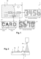
- FIG. 1 is illustrated a support body in card format according to the prior art exemplified here in the form of a bank chip card.
- the map serves as an observation test to highlight the problems to be solved and to allow the beginning of a solution to be glimpsed. It conventionally comprises a card body 1 personalized graphically and with a zone 2 on the left, presenting a tactile surface effect on the card body, said effect being obtained by depositing varnish by screen printing or material jet 6. On the right, there is a zone 3 whose surface does not include deliberately varnish on the surface.
- the test (or observation) card 1 presents 4 embossing characters such as a bank card number or other information which extends over the two zones 2 and 3.
- FIG 2 To the figure 2 is schematically illustrated the conventional varnishing step of the prior art 6a on a card 1 of the type of the figure 1 .
- the card 1 may conventionally comprise, according to the prior art, embossed zones 4 (hollows 7 and corresponding bumps 4) as well as zones comprising on the surface of added material 8 (hologram, marking) deposited by transfer, in particular by thermal transfer to the using a heat transfer film 9 (not shown in this figure but identical or similar to the film of the figure 2 ).
- the varnish jet 6a is respectively deposited on the card and respectively forms a layer 6b, 6c on the flat main surface of the card and on the embossing zones 4; Then the material 8 (eg a hologram, marked information) is hot transferred onto the layer of varnish 6b.
- the material 8 eg a hologram, marked information
- the methods of manufacturing a support body in card format with graphic personalization having a more or less smooth, rough, mirror or matte surface finish effect on said support body, respectively according to the prior art and according to the invention, include in common step 100 or (100i) which consists of supplying a support body 1 having a layer of material configured to allow marking by punching or lamination,
- the support body 1 is a chip card body obtained by lamination with a surface layer of plastic material such as ABS, PE, PET or PC.
- the body can also be obtained by injection and comprise a single layer. It can however be a card body without chip of different formats or surfaces or thickness.
- steps 100i, 105, 130i differs by a step 105 insofar as steps 100i and 130i are identical to steps 100, 130 of the prior art (illustrated in figure 4 ).
- step 105 said “layer of material configured to allow marking by punching” is exposed on the main external face
- the invention provides for obtaining said surface finishing effect by a marking step while being free of a varnish deposit step.
- the implementation of such a surface marking 105 is obtained by punching the surface or the outer layer of the card body.
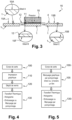
- the punching can be carried out in the preferred example with an installation 16 illustrated in picture 3 .
- the installation comprises punching means materialized here by a punch 10.
- the punch is configured with actuating means to exert a striking force or pressure (preferably hot) on a striking face.
- the striking face has a pattern in relief (here a hollow 11) relative to the main surface of the punch.
- the punching or marking 105 is carried out according to one embodiment using a punch 10 ( fig.3 ) preferably comprising a pattern 11 in relief on its striking surface intended to press or strike against the movie.
- relief 11 can be formed directly on film 12 rather than on punch 10.
- a punch with a flat striking head in particular can apply pressure on the support body, via the film 12, and form the corresponding relief 11 of the film on the surface of the support body by deformation (or stamping) of the main surface of the card body.
- the installation 16 shows a routing of the card in a position under a punch P with a relief 11 on the striking surface;
- the card is stamped using the punch 10 to mark the relief
- the marking is carried out by punching using the above punch through a film 12 or a ribbon interposed between the punch 10 and said main surface.
- the film in the example is a transparent film in PET material with a surface condition for a matte finish on the card. PET is preferred for temperature resistance, with the card being PVC or at least having a PVC outer layer.
- the invention has an installation 16 ( fig. 3 ) for graphical personalization of a smart card body with a surface touch effect on the card body.
- the installation may include means for conveying the card body to punching means 10.
- the card bodies have on the main surface a layer of material whose hardness allows marking by punching.
- the installation is a machine from the Kurz MM 7000 company.
- the film 12 is placed directly between the punch 10 and the card body 1.
- the film 12 is a PET polymer film of the Kurz company. It can be 12 ⁇ m thick. In mirror effect, the film has the glandzend reference 93324 and in matt effect, the film has the MAT reference 93325.
- the film or ribbon 12 may have at least the width of the card or may have at least the width corresponding to the relief pattern to be punched or the width of the punch.
- the film may be a film of a higher hardness than that of the surface layer of the card body.
- the film can be a metallic film.
- the film may preferably have a higher softening temperature than that of the surface layer of the card body.
- the film is in the form of a continuous ribbon and unwinds continuously between the punch and the card driven by a motor between two pulleys or drive rollers (or the unwinding of the film).
- the continuous tape 12 can be moved, at each punching or after a predetermined series of punchings, from one punching position to the next to present a new surface of unpunched tape.
- the installation can use a stepper motor (not shown).
- the film or tape may have a matte or mirror surface.
- a matte or mirrored surface effect is produced on the board due to the roughness or smoothness residing on the surface of the film.
- the film 12 has a rough surface state on its underside 15 F for a matte effect equivalent to matte-effect varnish.
- the card conveyed at the start of the route before punching has (for example) a smooth surface 15A (Detail A, fig. 3 ) or a clean PET surface.
- the card undergoes the pressure (preferably hot) of the punch through the film 12.
- the relief pattern 11 appearing on its striking face is reproduced through the film 12 on the external face of the card body.
- the punch may have a personalization pattern in relief and/or in hollow relative to a general surface of the punch.
- the pattern can take on expanses, diverse and varied forms. For example, gridlines, circles, symbols, logos, alphanumeric characters, etc. can be formed in relief on the striking face 11 of the punch.
- the patterns 11 on the punch can be of a higher dimensional level than that appearing on the surface of the film (for example, the relief (height, width can be 10 to 1000 times greater).
- the material of the polymer film or tape can be chosen from polyethylene terephthalate (PET), polycarbonate (PC), etc.
- the marking or punching is preferably carried out hot, for example between 100 and 250°C.
- the punching film or tape may itself have a relief formed elsewhere.
- the relief can be of a material identical to or distinct from that of the film or tape.
- the relief can be formed by additive or subtractive method.
- a relief pattern can be formed by 3D printing on the film or ribbon.
- the advantage is to be able to change the patterns to be punched or stamped on the card very easily by varying them all along a ribbon according to the graphic personalization needs.
- metal or plastic relief patterns (whose graphics are to be transposed onto the surface of the card) can be fixed to the ribbon, in particular by gluing.
- the method of the invention makes it possible to obtain a support body, in card format, with graphic personalization having a more or less smooth, rough, mirror or matte surface finish effect on said support body.
- the support body has a layer of material configured to allow marking by punching or lamination.
- the layer of material is exposed on the outer main face and has a surface finishing effect with relief patterns marked or formed in the material of said layer while being free of varnish.
- the outer layer of material may or may not be of the polymer type (metal, wood, etc.) and forms a finished main outer surface of the support body.
- the outer layer located at the level of the main surface of the card, may present on its outer face relief patterns formed in the thickness of the outer layer of material (the one located most outside of the card body) .
- the process of the invention can carry out several punches with different films and different punches.
- graphics to be reproduced on a support are on a first film and are reproduced using a punch with a flat punch head (without a raised pattern), then at another station, the process uses a second film presenting a 15F micro surface relief (or surface condition) for a tactile surface effect (matte or mirror) which is reproduced on the support using a punch with an equally flat striking head.
- the latter can be formed by embossing directly on the support or by inkjet directly on the card body.
- the film 12 can include both patterns to impart a matte surface finish and other patterns to impart a mirror finish on the support body 1. This gives the support body graphic personalization patterns visible by contrast of the different surface finish effects (matt or mirror) of the different patterns. Indeed, on their own, different surface finishes on different predetermined areas, can constitute a graphic personalization of the support body.
Description
L'invention concerne un procédé de fabrication d'un corps de support présentant un effet de surface.The invention relates to a method for producing a support body having a surface effect.
Il concerne particulièrement la fabrication de supports personnalisés graphiquement, et présentant un effet de surface, tel que mat ou miroir, et indiqué par la suite par « effet tactile » du fait qu'une différence d'effet (ou de traitement de surface), se détecte au toucher, sur le corps de support.It particularly relates to the manufacture of graphically personalized supports, and having a surface effect, such as matt or mirror, and subsequently indicated by "tactile effect" because a difference in effect (or surface treatment), can be detected by touch, on the support body.
L'invention concerne principalement des supports appartenant au domaine des cartes à puce (identité, bancaire, fidélité, accès...) et comportant des matériaux divers tels que du bois, du métal et/ou du plastique, du polymère naturel ou synthétique. Elle pourrait cependant concerner d'autres produits ou laminés notamment au format carte à puce bancaire standardisé ou non, avec ou sans puce électronique, des passeports, des feuilles laminées, des tickets radiofréquences (RFID).The invention mainly relates to supports belonging to the field of smart cards (identity, banking, loyalty, access, etc.) and comprising various materials such as wood, metal and/or plastic, natural or synthetic polymer. It could, however, relate to other products or laminates, in particular in the format of a standardized bank chip card or not, with or without an electronic chip, passports, laminated sheets, radiofrequency tickets (RFID).
Les cartes à puce peuvent avoir ou non une fonction radiofréquence et être du type à contacts et/ou sans-contact.Smart cards may or may not have a radio frequency function and be of the contact and/or contactless type.
L'invention vise plus particulièrement des cartes bancaires, crédit, débit, des cartes à capteur biométrique, des cartes à afficheur, des cartes bancaires embossées, et/ou avec logo de sécurité, hologramme, etc.The invention relates more particularly to bank cards, credit cards, debit cards, cards with a biometric sensor, cards with a display, embossed bank cards, and/or with a security logo, hologram, etc.
On sait obtenir des effets tactiles (mat ou miroir) sur la carte à puce par une méthode de sérigraphie au cours du processus de fabrication des cartes à puce.It is known to obtain tactile effects (matte or mirror) on the chip card by a screen printing method during the chip card manufacturing process.
Par définition pour l'ensemble du présent document, l'effet tactile, comme son nom l'indique, concerne le sens du toucher. Dès l'instant où un traitement de surface d'une carte permet d'obtenir une différence au toucher entre différentes textures (lisse, rugueux, veines de bois, toucher soft...) de carte, on traduit cette différence par un effet tactile présent sur la carte ou conféré à la carte par ledit traitement.By definition throughout this document, the tactile effect, as its name suggests, relates to the sense of touch. As soon as a surface treatment of a card makes it possible to obtain a difference to the touch between different textures (smooth, rough, wood grain, soft touch, etc.) of the card, this difference is translated by a tactile effect. present on the card or conferred on the card by said processing.
L'effet tactile est apporté par un dépôt d'une couche de vernis sur le dessus de produit final donnant une finition mat ou miroir en fonction du vernis utilisé.The tactile effect is provided by depositing a layer of varnish on top of the final product giving a matte or mirror finish depending on the varnish used.
Dans certains pays présentant des conditions climatiques élevées (température et humidité) ; Lors d'empilements de cartes à puce bancaires après fabrication, les inventeurs ont constaté un problème de migration d'éléments du panneau de signature disposé au verso de la carte bancaires, vers un vernis tactile (mat ou brillant) disposé sur la face avant des cartes.In some countries with high climatic conditions (temperature and humidity); When stacking bank smart cards after manufacture, the inventors observed a problem of migration of elements from the signature panel placed on the back of the bank card, to a tactile varnish (matt or glossy) placed on the front face of the maps.
Afin d'éviter ce problème, on peut utiliser des séparateurs (ou feuilles) entre les cartes, mais cela ajoute les étapes d'ajout et de retrait des séparateurs..In order to avoid this problem, one can use separators (or sheets) between the cards, but this adds the steps of adding and removing the separators.
Un autre problème technique réside dans la compatibilité du vernis tactile avec tous les processus (ou technique) de personnalisation utilisés : via laser, embossage (causant des fissures au sommet des zones embossées), transfert thermique (non compatibilité avec vernis tactile), estampage à chaud d'hologramme...Another technical problem lies in the compatibility of the tactile varnish with all the personalization processes (or techniques) used: via laser, embossing (causing cracks at the top of the embossed areas), thermal transfer (not compatible with tactile varnish), stamping with hot hologram...
Un marquage d'information de personnalisation par transfert thermique sur un corps de carte n'adhère pas bien quand ce dernier présente une couche de vernis en surface.A personalization information marking by thermal transfer on a card body does not adhere well when the latter has a layer of varnish on the surface.
De même les hologrammes, notamment en aluminium, déposés par transfert thermique n'adhérent pas bien en raison de la couche de vernis en surface.Similarly, holograms, in particular in aluminium, deposited by thermal transfer do not adhere well because of the layer of varnish on the surface.
Concernant l'embossage de caractères de personnalisation, il se produit des fissures au sommet des caractères embossés au niveau du vernis qui peuvent se propager dans les couches sous-jacentes du corps de carte.Regarding the embossing of personalization characters, there are cracks at the top of the embossed characters at the level of the varnish which can propagate into the underlying layers of the card body.
Une solution imaginée par les inventeurs est d'utiliser des plaques de métal avec surface gravées et/ou plus ou moins lisses (ou rugueuses) pour estamper à chaud des cartes et obtenir un état de surface très similaire à un effet tactile (mat ou brillant) d'un vernis ou présentant des éléments de personnalisation sur les surfaces externes des cartes. Toutefois, ce procédé impliquerait de disposer énormément de plaques gravées excessivement onéreuses pour une production à l'échelle industrielle.A solution imagined by the inventors is to use metal plates with an engraved and/or more or less smooth (or rough) surface to hot stamp cards and obtain a surface state very similar to a tactile effect (matte or shiny ) with a varnish or with personalization elements on the external surfaces of the cards. However, this method would involve having a lot of etched plates that are excessively expensive for production on an industrial scale.
En outre, il est nécessaire d'effectuer un bon positionnement des plaques gravées par rapport à l'impression offset (plaques avec picots de registration (ou de positionnement) qui permettent de positionner les feuilles par rapport à la gravure). Cette solution des inventeurs parait complexe, très onéreuse et de ce fait, plus adapté à des petites séries que des grandes séries industrielles.In addition, it is necessary to correctly position the engraved plates in relation to the offset printing (plates with registration (or positioning) pins which allow the sheets to be positioned in relation to the engraving). This solution of the inventors seems complex, very expensive and therefore more suitable for small series than large industrial series.
On connaît des films polymères de la société Kurz généralement utilisés pour supporter des matériaux de transfert thermique (métallisation, hologrammes...) afin de les transférer thermiquement et physiquement sur la carte (par estampage à chaud).Polymer films from the company Kurz are known, generally used to support thermal transfer materials (metallization, holograms, etc.) in order to transfer them thermally and physically onto the card (by hot stamping).
Ce type de film de la société Kurz semble être utilisé uniquement comme film-support pour véhiculer des matériaux ou autre élément (hologramme...) à transférer physiquement du film-support donneur vers un support receveur. Le film opère donc comme film-support de matériau de transfert à chaud, toujours associé au matériau ou à un élément à transférer physiquement et entièrement du film-support donneur à un autre support receveur de l'élément.This type of film from the Kurz company seems to be used only as a support film to convey materials or other element (hologram, etc.) to be physically transferred from the donor support film to a recipient support. The film therefore operates as a support film for heat transfer material, always associated with the material or with a element to be physically and entirely transferred from the donor support film to another receiver support for the element.
Le document
Le document
Le document
L'invention vise à résoudre les inconvénients précités.The invention aims to solve the aforementioned drawbacks.
L'invention a pour objectif un procédé de fabrication de support flexible au format carte (au sens large et de toutes dimensions) incluant une ou plusieurs étape(s) de personnalisation graphique) et présentant un effet de surface tactile qui ne présente pas les problèmes ci-dessus.The objective of the invention is a process for manufacturing a flexible support in card format (in the broad sense and of all dimensions) including one or more step(s) of graphic personalization) and having a tactile surface effect which does not present the problems above.
L'invention vise un procédé qui soit de préférence économique industriellement (à grande échelle de production).The invention relates to a method which is preferably industrially economical (on a large production scale).
Elle vise préférentiellement la fabrication et personnalisation des cartes à puce notamment bancaires (crédit, débit) ou passeports électroniques.It preferentially targets the manufacture and personalization of smart cards, in particular bank cards (credit, debit) or electronic passports.
L'invention propose un procédé de fabrication selon la revendication 1.The invention provides a method of manufacture according to
Ainsi, l'invention s'affranchit des inconvénients ci-dessus en supprimant le vernis (après maintes observations et considérations des inventeurs) et en obtenant un effet équivalent à celui du vernis, en mettant en œuvre une étape de finition par une technique de marquage de surface.Thus, the invention overcomes the above drawbacks by eliminating the varnish (after many observations and considerations by the inventors) and by obtaining an effect equivalent to that of the varnish, by implementing a finishing step by a marking technique of surface.
Les inventeurs ont en effet analysé la situation et déduit que le vernis était la cause des effets indésirables, visés ci-dessus, sur la carte.The inventors have in fact analyzed the situation and deduced that the varnish was the cause of the undesirable effects, referred to above, on the card.
La suppression du vernis (ainsi que ses avantages d'effet tactile), n'est rendue possible que grâce à une manière de personnalisation graphique pouvant procurer un rendu similaire et ce à un coût réduit et à des cadences industrielles.The elimination of the varnish (as well as its advantages of tactile effect), is made possible only thanks to a way of graphic personalization being able to get a similar rendering and this at a reduced cost and at industrial rates.
Pour des raisons de cadences industrielles et de coût, la personnalisation ou l'obtention de l'effet de surface de finition est réalisée par l'intermédiaire d'un poinçonnage de la surface de la carte à travers un film.For reasons of industrial rates and cost, the personalization or the obtaining of the surface finish effect is carried out by punching the surface of the card through a film.
Selon un mode préféré, un graphisme ou motif graphique selon un premier niveau d'échelle dit macroscopique est reproduit sur le poinçon tandis qu'un graphisme ou motif graphique à un second niveau d'échelle dit microscopique est reproduit sur le film. Le rapport entre les deux niveaux d'échelle premier et second susvisés peut être par exemple d'un facteur 10, 100, 1000 ou plus. Un motif ou relief sur le poinçon peut être plus prononcé ou plus large que celui réalisé sur le film ou inversement.According to a preferred mode, a graphic design or graphic pattern according to a first so-called macroscopic scale level is reproduced on the punch while a graphic design or graphic pattern at a second so-called microscopic scale level is reproduced on the film. The ratio between the two aforementioned first and second scale levels can for example be a factor of 10, 100, 1000 or more. A pattern or relief on the punch can be more pronounced or larger than that made on the film or vice versa.
Un effet de finition similaire au vernis mat ou miroir est obtenu par le recours à un film ayant en surface un état de surface avec plus ou moins d'aspérités ou d'irrégularités ou de lissage, permettant d'obtenir un effet similaire mat ou miroir.A finishing effect similar to matt or mirror varnish is obtained by using a film having a surface finish with more or less asperities or irregularities or smoothing, making it possible to obtain a similar matt or mirror effect. .
Selon d'autres caractéristiques :
- La couche est en matière polymère ;
- le film polymère est un ruban continu ;
- Le ruban continu est déplacé pas à pas d'un poinçonnage au suivant pour présenter une nouvelle surface de ruban non poinçonnée à chaque poinçonnage ou après une série prédéterminée de poinçonnage ;
- Le film ou ruban présente une surface mat ou miroir ;
- Le poinçon présente un motif de personnalisation en relief et/ou en creux par rapport à une surface générale du poinçon ;
- Le film ou ruban est un film polymère ;
- La matière du film ou ruban polymère est choisi parmi le polyéthylène téréphtalate (PET), le polycarbonate (PC
- Le marquage peut s'effectuer à chaud, par exemple entre 100 et 250°C ;
- La personnalisation graphique comprend un dépôt d'hologramme et/ou un embossage et/ou un marquage par transfert thermique et/ou personnalisation laser et/ou dépose de pavé de signature ;
- Le film comporte un motif graphique en relief et/ou un état de surface à effet mat ou miroir.
- The layer is made of polymer material;
- the polymer film is a continuous tape;
- The continuous tape is moved step by step from one punching to the next to present a new unpunched tape surface at each punching or after a predetermined series of punchings;
- The film or ribbon has a matte or mirror surface;
- The punch has a personalization pattern in relief and/or recessed relative to a general surface of the punch;
- The film or ribbon is a polymer film;
- The material of the film or polymer tape is chosen from polyethylene terephthalate (PET), polycarbonate (PC
- The marking can be carried out hot, for example between 100 and 250° C.;
- Graphic personalization includes hologram deposition and/or embossing and/or thermal transfer marking and/or laser personalization and/or signature pad deposition;
- The film has a graphic pattern in relief and/or a surface condition with a matte or mirror effect.
De préférence, la couche de matière est de préférence en matière polymère.Preferably, the layer of material is preferably made of polymer material.
-
La
figure 1 illustre une carte de test basée sur une carte à puce de l'art antérieur dont une zone 3 est exempte de vernis ;Therefigure 1 illustrates a test card based on a chip card of the prior art, anarea 3 of which is free of varnish; -
La
figure 2 illustre schématiquement le procédé d'obtention d'une carte à puce à effet mat ou miroir selon l'art antérieur ;Therefigure 2 schematically illustrates the process for obtaining a chip card with a matte or mirror effect according to the prior art; -
La
figure 3 illustre une installation pour la mise en œuvre du procédé de l'invention selon un mode de mise en œuvre préféré (avec recours à un film 12 intermédiaire) ;Therepicture 3 -
La
figure 4 illustre des étapes du procédé actuel de fabrication d'une carte à effet tactile (miroir ou mat);Therefigure 4 illustrates steps in the current process for making a tactile card (mirror or matte); -
La
figure 5 illustre des étapes du procédé de l'invention conforme au mode préféré de mise en oeuvre.Therefigure 5 illustrates steps of the method of the invention in accordance with the preferred mode of implementation.
A la
On peut constater visuellement que les caractères « 5678 » référencés 4 de la zone avec vernis présentent avec le temps des dégradations du vernis (fissures, craquelures (C1, C2) ainsi que des dégradations de la matière du corps de carte située dessous. De même pour les caractères « CARD » situées dans la zone 2 avec vernis, les caractères présentent des craquelures C3.It can be seen visually that the "5678" characters referenced 4 in the area with varnish show deterioration of the varnish over time (cracks, cracks (C1, C2) as well as deterioration of the material of the card body located underneath. Similarly for the "CARD" characters located in
A contrario, les caractères « 3456 » dans la zone 3 (sans vernis) ne présentent pas de telles dégradations physiques dans la matière et mécaniques sous l'embossage.Conversely, the "3456" characters in zone 3 (without varnish) do not show such physical degradation in the material and mechanical damage under the embossing.
Cette carte test réalisée par les inventeurs met en avant notamment les effets ou comportement du vernis.This test card produced by the inventors highlights in particular the effects or behavior of the varnish.
A la
La carte 1 peut comporter classiquement selon l'art antérieur des zones embossées 4 (creux 7 et bosses correspondantes 4) ainsi que des zones comportant en surface de la matière ajoutée 8 (hologramme, marquage) déposée par transfert notamment par transfert thermique à l'aide d'un film de transfert à chaud 9 (non représenté sur cette figure mais identique ou similaire au film de la
Selon l'art antérieur, le jet de vernis 6a est respectivement déposé sur la carte et forme respectivement une couche 6b, 6c sur la surface principale plane de la carte et sur les zones d'embossage 4 ; Puis la matière 8 (exemple un hologramme, une information marquée) est transférée à chaud sur la couche de vernis 6b.According to the prior art, the
A la
Pour permettre une comparaison de l'invention avec l'art antérieur, nous décrivons au préalable à la
Les procédés de fabrication d'un corps de support au format carte avec une personnalisation graphique présentant un effet de finition de surface plus ou moins lisse, rugueux, miroir ou mat sur ledit corps de support, respectivement selon l'art antérieur et selon l'invention, comprennent en commun l'étape 100 ou (100i) qui consiste en la fourniture d'un corps de support 1 présentant une couche de matière configurée pour permettre un marquage par poinçonnage ou lamination,The methods of manufacturing a support body in card format with graphic personalization having a more or less smooth, rough, mirror or matte surface finish effect on said support body, respectively according to the prior art and according to the invention, include in
Dans l'exemple, le corps support 1 est un corps de carte à puce obtenu par lamination avec une couche de matière plastique en surface telle que de l'ABS, du PE, PET ou PC. Le corps peut être aussi obtenu par injection et comprendre une seule couche. Il peut toutefois être un corps de carte sans puce de différents formats ou surfaces ou d'épaisseur.In the example, the
Le cas échéant, le corps peut comporter en surface une couche métallique (Aluminium, argent, platine, acier, or ou alliage).
- A l'étape 110 (
fig. 4 ), l'art antérieur met en oeuvre une étape d'impression graphique (par technique sérigraphique, jet d'encre, offset...) sur le corpssupport 1 ou ladite couche externe; - A
l'étape 120, l'art antérieur met en oeuvre une étape de pulvérisation 6a ou de dépôt d'une couche de vernis à la surface du corps support (ici corps de carte 1 - voir lazone 2 de lafigure.1 ) ;
- A
l'étape 130 finale, l'art antérieur met en oeuvre une ou plusieurs étape(s) d'embossage et/ou de marquage par poinçonnage pour créer un relief de surface, ou de marquage par transfert thermique avec dépôt ou transfert de matière, tel un hologramme ou une information de personnalisation quelconque.
- At step 110 (
fig. 4 ), the prior art implements a step of graphic printing (by screen printing, inkjet, offset, etc.) on thesupport body 1 or said outer layer; - At
step 120, the prior art implements astep 6a of spraying or depositing a layer of varnish on the surface of the support body (here card body 1 - seezone 2 of thefigure 1 );
- At the
final step 130, the prior art implements one or more step(s) of embossing and/or marking by punching to create a surface relief, or marking by thermal transfer with deposition or transfer of material , such as a hologram or any personalization information.
Au contraire, le procédé de l'invention (illustré
A l'étape 105, ladite « couche de matière configurée pour permettre un marquage par poinçonnage » est exposée en face principale externe ;At
En outre l'invention prévoit d'obtenir ledit effet de finition de surface par une étape de marquage tout en étant exempt d'une étape de dépôt de vernis.Furthermore, the invention provides for obtaining said surface finishing effect by a marking step while being free of a varnish deposit step.
La mise en oeuvre d'un tel marquage de surface 105 est obtenu par poinçonnage de la surface ou de la couche externe du corps de carte. Le poinçonnage peut s'effectuer dans l'exemple préféré avec une installation 16 illustrée à la
L'installation comprend des moyens de poinçonnage matérialisés ici par un poinçon 10. Le poinçon est configuré avec des moyens d'actionnement pour exercer une force de frappe ou de pression (de préférence à chaud) sur une face de frappe. La face de frappe présente un motif en relief (ici un creux 11) par rapport à la surface principale du poinçon.The installation comprises punching means materialized here by a
Le poinçonnage ou marquage 105 s'effectue selon un mode de réalisation à l'aide d'un poinçon 10 (
Alternativement (selon le mode préféré avec film intermédiaire 12), le relief 11 peut être formé directement sur le film 12 plutôt que sur le poinçon 10. Puis, un poinçon à tête de frappe plate notamment (sans relief 11), peut appliquer une pression sur le corps support, via le film 12, et former le relief 11 correspondant du film à la surface du corps-support par déformation (ou emboutissage) de la surface principale du corps de carte.Alternatively (according to the preferred mode with intermediate film 12),
L'installation 16 montre un acheminement de la carte dans une position sous un poinçon P avec un relief 11 en surface de frappe ; La carte est frappée à l'aide du poinçon 10 pour marquer le reliefThe
Selon l'invention, le marquage s'effectue par poinçonnage à l'aide du poinçon ci-dessus à travers un film 12 ou un ruban interposé entre le poinçon 10 et ladite surface principale. Le film dans l'exemple est un film transparent en matière PET avec un état de surface pour une finition mate sur la carte. Le PET est préféré pour résister à la température, la carte étant en PVC ou du moins ayant une couche externe en PVC.According to the invention, the marking is carried out by punching using the above punch through a
Pour cela, l'invention dispose d'une installation 16 (
Les corps de carte présentent en surface principale une couche de matière dont la dureté permet un marquage par poinçonnage.The card bodies have on the main surface a layer of material whose hardness allows marking by punching.
L'installation comprend des moyens de poinçonnage 10, 11 ou de marquage de la surface de la carte. Ces moyens comprennent un poinçon 10 avec une face de frappe et un motif en relief 11 sur sa surface de frappe ; Un plateau (ou enclume) pour supporter la carte et contre réagir à la pression du poinçon n'est pas représentée.
L'installation 16 comprend des moyens d'acheminement (ou d'insertion) pour interposer (ou insérer)un film 12 entre le poinçon 10 et lasurface 15A de la carte (surface visible sur le détail Afig. 3 ). Pour cela, l'installation peut prévoir des rouleaux dévidoirs et de rembobinage (non représentés) pour dévider et pourrembobiner un film 12 en ruban et des dépileurs empileurs (non représentés) de corps de carte.- L'installation comprend des moyens pour assurer ledit marquage, par poinçonnage à
travers le film 12 interposé entre le poinçon 10 et ladite surface principale 15A.
- The
installation 16 comprises routing (or insertion) means for interposing (or inserting) afilm 12 between thepunch 10 and thesurface 15A of the card (surface visible on detail Afig. 3 ). For this, the installation can provide unwinding and rewinding rollers (not shown) for unwinding and rewinding afilm 12 in ribbon and card body unstackers (not shown). - The installation comprises means for ensuring said marking, by punching through the
film 12 interposed between thepunch 10 and the saidmain surface 15A.
Dans l'exemple, l'installation est une machine de la société Kurz MM 7000. Le film 12 est placé directement entre le poinçon 10 et le corps de carte 1. Dans l'exemple également, le film 12 est un film polymère PET de la société Kurz. Il peut être d'une épaisseur de 12 um. En effet miroir, le film a la référence glandzend 93324 et en effet mat, le film a la référence MAT 93325.In the example, the installation is a machine from the Kurz MM 7000 company. The
Le film ou ruban 12 peut avoir au moins la largeur de la carte ou peut avoir au moins la largeur correspondant au motif en relief à poinçonner ou la largeur du poinçon. De préférence, le film peut être un film d'une dureté supérieure à celle de la couche de surface du corps de carte. Le film peut être un film métallique.The film or
De préférence, en cas de poinçonnage à chaud, le film peut présenter de préférence une température de ramollissement supérieure à celle de la couche de surface du corps de carte.Preferably, in the event of hot punching, the film may preferably have a higher softening temperature than that of the surface layer of the card body.
De préférence, le film (ou ruban) est sous forme d'un ruban continu et se déroule en continu entre le poinçon et la carte entraîné par un moteur entre deux poulies ou rouleaux d'entrainement (ou de déroulé du film).Preferably, the film (or ribbon) is in the form of a continuous ribbon and unwinds continuously between the punch and the card driven by a motor between two pulleys or drive rollers (or the unwinding of the film).
Le ruban continu 12 être déplacé, à chaque poinçonnage ou après une série prédéterminée de poinçonnage, d'une position de poinçonnage à la suivante pour présenter une nouvelle surface de ruban non poinçonnée. Pour cela, l'installation peut utiliser un moteur pas à pas (non représenté).The
Selon une caractéristique, le film ou ruban peut présenter une surface mate ou miroir. Un effet de surface mat ou miroir est produit sur la carte du fait de la rugosité ou du lissage résidant à la surface du film. Ainsi, on peut obtenir un effet similaire à celui d'un vernis.According to one characteristic, the film or tape may have a matte or mirror surface. A matte or mirrored surface effect is produced on the board due to the roughness or smoothness residing on the surface of the film. Thus, one can obtain an effect similar to that of a varnish.
A la
La carte acheminée en début de parcours avant poinçonnage présente (par exemple) une surface lisse 15A (Détail A,
Au poste de poinçonnage, la carte subit la pression (de préférence à chaud) du poinçon à travers le film 12.At the punching station, the card undergoes the pressure (preferably hot) of the punch through the
Le motif en relief 11 figurant sur sa face de frappe est reproduit à travers le film 12 sur la face externe du corps de carte.The
De même, l'état de surface (ou aspérités) 15F (détail B) figurant à la surface du film 12 est reproduit à la surface du corps de carte sous forme d'un état de surface correspondant 15B (Détail C).Similarly, the surface condition (or asperities) 15F (detail B) appearing on the surface of the
Selon une caractéristique, le poinçon peut présenter un motif de personnalisation en relief et/ou en creux par rapport à une surface générale du poinçon. Le motif peut prendre des étendues, des formes diverses et variées. Par exemple, un quadrillage, des cercle, des symboles, des logos, des caractères alphanumériques, etc. peuvent être formés en relief sur la face de frappe 11 du poinçon. Les motifs 11 sur le poinçon peuvent être d'un niveau dimensionnel plus important que celui figurant à la surface du film (par exemple, le relief (hauteur, largeur peut être 10 à 1000 fois plus important).According to one characteristic, the punch may have a personalization pattern in relief and/or in hollow relative to a general surface of the punch. The pattern can take on expanses, diverse and varied forms. For example, gridlines, circles, symbols, logos, alphanumeric characters, etc. can be formed in relief on the
La matière du film ou du ruban polymère peut être choisi parmi le polyéthylène téréphtalate (PET), le polycarbonate (PC), etc.The material of the polymer film or tape can be chosen from polyethylene terephthalate (PET), polycarbonate (PC), etc.
Le marquage ou poinçonnage s'effectue de préférence à chaud par exemple entre 100 à 250°C.The marking or punching is preferably carried out hot, for example between 100 and 250°C.
Alternativement, le film ou ruban de poinçonnage peut présenter luimême un relief formé par ailleurs. Le relief peut être d'une matière identique ou distincte de celle du film ou ruban.Alternatively, the punching film or tape may itself have a relief formed elsewhere. The relief can be of a material identical to or distinct from that of the film or tape.
Le relief peut être formé par méthode additive ou soustractive. Par exemple, un motif en relief peut être formé par imprimante 3D sur le film ou ruban.The relief can be formed by additive or subtractive method. For example, a relief pattern can be formed by 3D printing on the film or ribbon.
L'avantage est de pouvoir changer les motifs à poinçonner ou estampiller sur la carte très facilement en les faisant varier tout le long d'un ruban selon les besoins de personnalisation graphique.The advantage is to be able to change the patterns to be punched or stamped on the card very easily by varying them all along a ribbon according to the graphic personalization needs.
Alternativement, des motifs en relief métalliques ou plastiques (dont le graphisme est à transposer sur la surface de la carte) peuvent être fixés sur le ruban notamment par collage.Alternatively, metal or plastic relief patterns (whose graphics are to be transposed onto the surface of the card) can be fixed to the ribbon, in particular by gluing.
Ainsi, le procédé de l'invention permet d'obtenir un corps de support, au format carte, avec une personnalisation graphique présentant un effet de finition de surface plus ou moins lisse, rugueux, miroir ou mat sur ledit corps de support.Thus, the method of the invention makes it possible to obtain a support body, in card format, with graphic personalization having a more or less smooth, rough, mirror or matte surface finish effect on said support body.
Le corps de support présente une couche de matière configurée pour permettre un marquage par poinçonnage ou lamination.The support body has a layer of material configured to allow marking by punching or lamination.
Selon une caractéristique, la couche de matière est exposée en face principale externe et présente un effet de finition de surface avec des motifs en relief marqués ou formés dans la matière de ladite couche tout en étant exempt de vernis.According to one characteristic, the layer of material is exposed on the outer main face and has a surface finishing effect with relief patterns marked or formed in the material of said layer while being free of varnish.
La couche de matière externe peut être de type polymère ou non (métal, bois..) et forme une surface principale externe finie du corps de support.The outer layer of material may or may not be of the polymer type (metal, wood, etc.) and forms a finished main outer surface of the support body.
La couche externe, située au niveau de la surface principale de la carte, peut présenter sur sa face externe des motifs en relief formés dans l'épaisseur de la couche externe de matière (celle située le plus à l'extérieur du corps de carte).The outer layer, located at the level of the main surface of the card, may present on its outer face relief patterns formed in the thickness of the outer layer of material (the one located most outside of the card body) .
Le cas échéant, le procédé de l'invention peut réaliser plusieurs poinçonnages avec des films différents et des poinçons différents. Par exemple, des graphiques à reproduire sur un support sont sur un premier film et sont reproduit à l'aide d'un poinçon à tête de frappe plat (sans motif en relief), puis à un autre poste, le procédé utilise un second film présentant un micro relief de surface 15F (ou état de surface) pour un effet de surface tactile (mat ou miroir) qui est reproduit sur le support à l'aide d'un poinçon à tête de frappe également plat.If necessary, the process of the invention can carry out several punches with different films and different punches. For example, graphics to be reproduced on a support are on a first film and are reproduced using a punch with a flat punch head (without a raised pattern), then at another station, the process uses a second film presenting a 15F micro surface relief (or surface condition) for a tactile surface effect (matte or mirror) which is reproduced on the support using a punch with an equally flat striking head.
Par la suite s'il est nécessaire de reproduire un numéro bancaire, ce dernier peut être formé par embossage directement sur le support ou par jet d'encre directement sur le corps de carte.Subsequently, if it is necessary to reproduce a bank number, the latter can be formed by embossing directly on the support or by inkjet directly on the card body.
Selon une variante de mise en oeuvre, le film 12 peut comporter à la fois des motifs pour conférer une finition de surface mat et d'autres motifs pour conférer une finition miroir sur le corps de support 1. On obtient ainsi sur le corps de support des motifs de personnalisation graphique visibles par contraste des différents effets de finition de surface (mats ou miroirs) des différents motifs. En effet, à elles seules, différentes finitions de surface sur des zones prédéterminées différentes, peuvent constituer une personnalisation graphique du corps de support.According to a variant implementation, the
Claims (13)
- Method for producing a support body (1), in card format, with a graphic personalization (15B, 8, 4) and having, on said support body, a surface finishing effect that is smooth, rough, mirror or mat to a greater or lesser extent,said method comprising the step of providing a support body having a layer of material (1) designed to allow marking by punching, so that said layer of material (1) is exposed on the outer main face (15A) and said surface finishing effect (15B) is equivalent to that of a varnish and is obtained by a marking step while being free of a varnish application step,characterized in that said marking is carried out by punching through a film (12) interposed between the punch (10) and said outer main surface (15A).
- Method according to the preceding claim, characterized in that the film (12) is in the form of a continuous tape.
- Method according to the preceding claim, characterized in that the continuous tape (12) is moved step by step from one punch strike to the next in order to provide a new non-punched tape surface with each punch strike or after a predetermined series of punch strikes.
- Method according to any of claims 1 to 3, characterized in that the film or tape (12) has a mat or mirror surface (15F).
- Method according to any of claims 1 to 4, characterized in that the punch (10) has a personalization pattern (11) that is raised and/or recessed relative to a general surface of the punch.
- Method according to any of claims 1 to 5, characterized in that the film or tape is a polymer or metal material.
- Method according to the preceding claim, characterized in that the material of the polymer film or tape is selected from polyethylene terephthalate (PET) and polycarbonate (PC).
- Method according to any of the preceding claims, characterized in that the marking or punching is carried out hot between 100 to 250°C.
- Method according to the preceding claim, characterized in that said graphic personalization comprises hologram application and/or embossing (7, 6c) and/or thermal transfer marking.
- Method according to any of claims 1 to 9, characterized in that the film comprises a raised graphic pattern and/or a surface finish with a mat or mirror effect.
- Method according to any of claims 1 to 10, characterized in that a plurality of punch strikes are performed using different films and different punches.
- Method according to any of claims 1 to 11, characterized in that said layer of material is made of polymer or metal material.
- Method according to any of claims 1 to 12, wherein the support body forms a smart bank card body.
Applications Claiming Priority (2)
| Application Number | Priority Date | Filing Date | Title |
|---|---|---|---|
| EP18306165.4A EP3620306A1 (en) | 2018-09-04 | 2018-09-04 | Method for producing a chip support having a surface effect |
| PCT/EP2019/073199 WO2020048885A1 (en) | 2018-09-04 | 2019-08-30 | Method for producing a chip support with a surface effect |
Publications (3)
| Publication Number | Publication Date |
|---|---|
| EP3847035A1 EP3847035A1 (en) | 2021-07-14 |
| EP3847035C0 EP3847035C0 (en) | 2023-07-19 |
| EP3847035B1 true EP3847035B1 (en) | 2023-07-19 |
Family
ID=63528678
Family Applications (2)
| Application Number | Title | Priority Date | Filing Date |
|---|---|---|---|
| EP18306165.4A Withdrawn EP3620306A1 (en) | 2018-09-04 | 2018-09-04 | Method for producing a chip support having a surface effect |
| EP19758996.3A Active EP3847035B1 (en) | 2018-09-04 | 2019-08-30 | Method for producing a chip support having a surface effect |
Family Applications Before (1)
| Application Number | Title | Priority Date | Filing Date |
|---|---|---|---|
| EP18306165.4A Withdrawn EP3620306A1 (en) | 2018-09-04 | 2018-09-04 | Method for producing a chip support having a surface effect |
Country Status (4)
| Country | Link |
|---|---|
| US (1) | US11562193B2 (en) |
| EP (2) | EP3620306A1 (en) |
| CN (1) | CN113242797A (en) |
| WO (1) | WO2020048885A1 (en) |
Families Citing this family (1)
| Publication number | Priority date | Publication date | Assignee | Title |
|---|---|---|---|---|
| US11410012B2 (en) * | 2019-08-01 | 2022-08-09 | Global Card Systems Company Ltd. | Method of manufacturing RFID access card from novel materials |
Family Cites Families (8)
| Publication number | Priority date | Publication date | Assignee | Title |
|---|---|---|---|---|
| BE792488A (en) * | 1971-12-08 | 1973-03-30 | Dainippon Printing Co Ltd | IDENTIFICATION CARDS AND METHOD FOR MANUFACTURING SUCH CARDS |
| US4325196A (en) * | 1977-12-16 | 1982-04-20 | G.A.O. Gesellschaft Fur Automation Und Organisation Mbh | Multilayer identification cards with relief-like surface |
| DE59508233D1 (en) * | 1994-11-18 | 2000-05-31 | Giesecke & Devrient Gmbh | METHOD FOR PRODUCING A DATA CARRIER |
| JP2003191419A (en) * | 2001-12-28 | 2003-07-08 | Mitsubishi Polyester Film Copp | Polyester film for ic card |
| CN1286665C (en) * | 2003-11-28 | 2006-11-29 | 汕头市东田转印有限公司 | Process for producing transfer printing films having a dull surface and a bright surface, and product made thereby |
| JP4142086B1 (en) | 2007-09-20 | 2008-08-27 | 日本カラリング株式会社 | Card oversheet |
| GB201203183D0 (en) * | 2012-02-24 | 2012-04-11 | Qinetiq Ltd | Optical multilayer |
| EP3007404A1 (en) | 2014-10-10 | 2016-04-13 | Gemalto Sa | Remote personalization of secure elements cooperating with telecommunication terminals |
-
2018
- 2018-09-04 EP EP18306165.4A patent/EP3620306A1/en not_active Withdrawn
-
2019
- 2019-08-30 EP EP19758996.3A patent/EP3847035B1/en active Active
- 2019-08-30 CN CN201980065625.7A patent/CN113242797A/en active Pending
- 2019-08-30 WO PCT/EP2019/073199 patent/WO2020048885A1/en unknown
- 2019-08-30 US US17/273,515 patent/US11562193B2/en active Active
Also Published As
| Publication number | Publication date |
|---|---|
| CN113242797A (en) | 2021-08-10 |
| EP3847035A1 (en) | 2021-07-14 |
| WO2020048885A1 (en) | 2020-03-12 |
| EP3847035C0 (en) | 2023-07-19 |
| EP3620306A1 (en) | 2020-03-11 |
| US20210201103A1 (en) | 2021-07-01 |
| US11562193B2 (en) | 2023-01-24 |
Similar Documents
| Publication | Publication Date | Title |
|---|---|---|
| EP1448392B1 (en) | Method for making an article comprising a sheet and at least an element directly mounted thereon | |
| EP2132684B1 (en) | Method for producing electronic cards including at least one printed pattern | |
| PT1467871E (en) | Steel gravure method for the production of a security document, steel gravure plate and intermediate product for the same and method for production thereof | |
| EP3847035B1 (en) | Method for producing a chip support having a surface effect | |
| WO2019115299A1 (en) | Method for customising/marking a smart card | |
| CA2448887C (en) | Method and apparatus for producing a portable data carrier | |
| JP5685874B2 (en) | Personal authentication medium | |
| EP1689595B1 (en) | Method for producing a security document and a corresponding document | |
| FR2972135A1 (en) | HOT AND PRESSURE TRANSFER MACHINE OF A PROTECTIVE LAYER OF A SUBSTRATE | |
| JP5708109B2 (en) | Card and manufacturing method thereof | |
| EP2452825B1 (en) | Method for making an imprint on an article | |
| EP2572895B1 (en) | Imprint with two graphic elements | |
| EP3072086B1 (en) | Security document and method of manufacture thereof | |
| WO2012126888A1 (en) | Process for printing a card body with a pattern printed in metallic ink and associated printed card | |
| US20130309447A1 (en) | Lamination plate assembly | |
| TW202045361A (en) | Multilayer article and process for producing a multilayer article | |
| FR3041563B1 (en) | METHOD FOR MANUFACTURING A LAMINATED POLYMER CARD HAVING A VISUAL EFFECT OF TRANSPARENCY |
Legal Events
| Date | Code | Title | Description |
|---|---|---|---|
| STAA | Information on the status of an ep patent application or granted ep patent |
Free format text: STATUS: UNKNOWN |
|
| STAA | Information on the status of an ep patent application or granted ep patent |
Free format text: STATUS: THE INTERNATIONAL PUBLICATION HAS BEEN MADE |
|
| PUAI | Public reference made under article 153(3) epc to a published international application that has entered the european phase |
Free format text: ORIGINAL CODE: 0009012 |
|
| STAA | Information on the status of an ep patent application or granted ep patent |
Free format text: STATUS: REQUEST FOR EXAMINATION WAS MADE |
|
| 17P | Request for examination filed |
Effective date: 20210406 |
|
| AK | Designated contracting states |
Kind code of ref document: A1 Designated state(s): AL AT BE BG CH CY CZ DE DK EE ES FI FR GB GR HR HU IE IS IT LI LT LU LV MC MK MT NL NO PL PT RO RS SE SI SK SM TR |
|
| DAV | Request for validation of the european patent (deleted) | ||
| DAX | Request for extension of the european patent (deleted) | ||
| RAP1 | Party data changed (applicant data changed or rights of an application transferred) |
Owner name: THALES DIS FRANCE SAS |
|
| STAA | Information on the status of an ep patent application or granted ep patent |
Free format text: STATUS: EXAMINATION IS IN PROGRESS |
|
| 17Q | First examination report despatched |
Effective date: 20220502 |
|
| GRAP | Despatch of communication of intention to grant a patent |
Free format text: ORIGINAL CODE: EPIDOSNIGR1 |
|
| STAA | Information on the status of an ep patent application or granted ep patent |
Free format text: STATUS: GRANT OF PATENT IS INTENDED |
|
| INTG | Intention to grant announced |
Effective date: 20230203 |
|
| GRAS | Grant fee paid |
Free format text: ORIGINAL CODE: EPIDOSNIGR3 |
|
| GRAA | (expected) grant |
Free format text: ORIGINAL CODE: 0009210 |
|
| STAA | Information on the status of an ep patent application or granted ep patent |
Free format text: STATUS: THE PATENT HAS BEEN GRANTED |
|
| AK | Designated contracting states |
Kind code of ref document: B1 Designated state(s): AL AT BE BG CH CY CZ DE DK EE ES FI FR GB GR HR HU IE IS IT LI LT LU LV MC MK MT NL NO PL PT RO RS SE SI SK SM TR |
|
| REG | Reference to a national code |
Ref country code: GB Ref legal event code: FG4D Free format text: NOT ENGLISH |
|
| REG | Reference to a national code |
Ref country code: CH Ref legal event code: EP |
|
| REG | Reference to a national code |
Ref country code: DE Ref legal event code: R096 Ref document number: 602019033089 Country of ref document: DE |
|
| REG | Reference to a national code |
Ref country code: IE Ref legal event code: FG4D Free format text: LANGUAGE OF EP DOCUMENT: FRENCH |
|
| U01 | Request for unitary effect filed |
Effective date: 20230810 |
|
| U07 | Unitary effect registered |
Designated state(s): AT BE BG DE DK EE FI FR IT LT LU LV MT NL PT SE SI Effective date: 20230816 |
|
| U20 | Renewal fee paid [unitary effect] |
Year of fee payment: 5 Effective date: 20230914 |
|
| REG | Reference to a national code |
Ref country code: LT Ref legal event code: MG9D |
|
| PG25 | Lapsed in a contracting state [announced via postgrant information from national office to epo] |
Ref country code: GR Free format text: LAPSE BECAUSE OF FAILURE TO SUBMIT A TRANSLATION OF THE DESCRIPTION OR TO PAY THE FEE WITHIN THE PRESCRIBED TIME-LIMIT Effective date: 20231020 |
|
| PG25 | Lapsed in a contracting state [announced via postgrant information from national office to epo] |
Ref country code: IS Free format text: LAPSE BECAUSE OF FAILURE TO SUBMIT A TRANSLATION OF THE DESCRIPTION OR TO PAY THE FEE WITHIN THE PRESCRIBED TIME-LIMIT Effective date: 20231119 |
|
| PG25 | Lapsed in a contracting state [announced via postgrant information from national office to epo] |
Ref country code: RS Free format text: LAPSE BECAUSE OF FAILURE TO SUBMIT A TRANSLATION OF THE DESCRIPTION OR TO PAY THE FEE WITHIN THE PRESCRIBED TIME-LIMIT Effective date: 20230719 Ref country code: NO Free format text: LAPSE BECAUSE OF FAILURE TO SUBMIT A TRANSLATION OF THE DESCRIPTION OR TO PAY THE FEE WITHIN THE PRESCRIBED TIME-LIMIT Effective date: 20231019 Ref country code: IS Free format text: LAPSE BECAUSE OF FAILURE TO SUBMIT A TRANSLATION OF THE DESCRIPTION OR TO PAY THE FEE WITHIN THE PRESCRIBED TIME-LIMIT Effective date: 20231119 Ref country code: HR Free format text: LAPSE BECAUSE OF FAILURE TO SUBMIT A TRANSLATION OF THE DESCRIPTION OR TO PAY THE FEE WITHIN THE PRESCRIBED TIME-LIMIT Effective date: 20230719 Ref country code: GR Free format text: LAPSE BECAUSE OF FAILURE TO SUBMIT A TRANSLATION OF THE DESCRIPTION OR TO PAY THE FEE WITHIN THE PRESCRIBED TIME-LIMIT Effective date: 20231020 |
|
| PG25 | Lapsed in a contracting state [announced via postgrant information from national office to epo] |
Ref country code: PL Free format text: LAPSE BECAUSE OF FAILURE TO SUBMIT A TRANSLATION OF THE DESCRIPTION OR TO PAY THE FEE WITHIN THE PRESCRIBED TIME-LIMIT Effective date: 20230719 |
|
| REG | Reference to a national code |
Ref country code: CH Ref legal event code: PL |