EP3847006B1 - Carter en materiau composite avec raidisseur integre - Google Patents
Carter en materiau composite avec raidisseur integre Download PDFInfo
- Publication number
- EP3847006B1 EP3847006B1 EP19783584.6A EP19783584A EP3847006B1 EP 3847006 B1 EP3847006 B1 EP 3847006B1 EP 19783584 A EP19783584 A EP 19783584A EP 3847006 B1 EP3847006 B1 EP 3847006B1
- Authority
- EP
- European Patent Office
- Prior art keywords
- casing
- stiffening element
- last turn
- layers
- fiber texture
- Prior art date
- Legal status (The legal status is an assumption and is not a legal conclusion. Google has not performed a legal analysis and makes no representation as to the accuracy of the status listed.)
- Active
Links
- 239000002131 composite material Substances 0.000 title claims description 29
- 239000003351 stiffener Substances 0.000 title description 8
- 238000004804 winding Methods 0.000 claims description 32
- 239000000835 fiber Substances 0.000 claims description 31
- 239000011159 matrix material Substances 0.000 claims description 25
- 230000002787 reinforcement Effects 0.000 claims description 22
- 238000009941 weaving Methods 0.000 claims description 17
- 238000004519 manufacturing process Methods 0.000 claims description 14
- 238000000034 method Methods 0.000 claims description 10
- 238000000280 densification Methods 0.000 claims description 7
- 210000003850 cellular structure Anatomy 0.000 claims 2
- 239000010410 layer Substances 0.000 description 38
- 229920005989 resin Polymers 0.000 description 17
- 239000011347 resin Substances 0.000 description 17
- 238000011144 upstream manufacturing Methods 0.000 description 9
- 230000005284 excitation Effects 0.000 description 8
- 230000014759 maintenance of location Effects 0.000 description 8
- 239000000919 ceramic Substances 0.000 description 6
- 239000007788 liquid Substances 0.000 description 6
- 239000002243 precursor Substances 0.000 description 6
- 239000000243 solution Substances 0.000 description 6
- OKTJSMMVPCPJKN-UHFFFAOYSA-N Carbon Chemical compound [C] OKTJSMMVPCPJKN-UHFFFAOYSA-N 0.000 description 5
- 229910052799 carbon Inorganic materials 0.000 description 5
- 238000010438 heat treatment Methods 0.000 description 5
- 239000000463 material Substances 0.000 description 5
- 238000009745 resin transfer moulding Methods 0.000 description 5
- 230000010354 integration Effects 0.000 description 4
- 230000015572 biosynthetic process Effects 0.000 description 3
- 238000004364 calculation method Methods 0.000 description 3
- 239000011248 coating agent Substances 0.000 description 3
- 238000000576 coating method Methods 0.000 description 3
- 239000003822 epoxy resin Substances 0.000 description 3
- 238000002347 injection Methods 0.000 description 3
- 239000007924 injection Substances 0.000 description 3
- 229920000647 polyepoxide Polymers 0.000 description 3
- 229920000642 polymer Polymers 0.000 description 3
- 238000006116 polymerization reaction Methods 0.000 description 3
- 230000008569 process Effects 0.000 description 3
- KWGRBVOPPLSCSI-WPRPVWTQSA-N (-)-ephedrine Chemical compound CN[C@@H](C)[C@H](O)C1=CC=CC=C1 KWGRBVOPPLSCSI-WPRPVWTQSA-N 0.000 description 2
- 238000004026 adhesive bonding Methods 0.000 description 2
- 239000004760 aramid Substances 0.000 description 2
- 229920003235 aromatic polyamide Polymers 0.000 description 2
- 230000006835 compression Effects 0.000 description 2
- 238000007906 compression Methods 0.000 description 2
- 239000011521 glass Substances 0.000 description 2
- 238000005470 impregnation Methods 0.000 description 2
- 229920003257 polycarbosilane Polymers 0.000 description 2
- 229920001709 polysilazane Polymers 0.000 description 2
- 230000000717 retained effect Effects 0.000 description 2
- HBMJWWWQQXIZIP-UHFFFAOYSA-N silicon carbide Chemical compound [Si+]#[C-] HBMJWWWQQXIZIP-UHFFFAOYSA-N 0.000 description 2
- 229910010271 silicon carbide Inorganic materials 0.000 description 2
- 239000002904 solvent Substances 0.000 description 2
- 210000003462 vein Anatomy 0.000 description 2
- XQUPVDVFXZDTLT-UHFFFAOYSA-N 1-[4-[[4-(2,5-dioxopyrrol-1-yl)phenyl]methyl]phenyl]pyrrole-2,5-dione Chemical compound O=C1C=CC(=O)N1C(C=C1)=CC=C1CC1=CC=C(N2C(C=CC2=O)=O)C=C1 XQUPVDVFXZDTLT-UHFFFAOYSA-N 0.000 description 1
- 229920000049 Carbon (fiber) Polymers 0.000 description 1
- 239000004593 Epoxy Substances 0.000 description 1
- 229920000784 Nomex Polymers 0.000 description 1
- 239000004642 Polyimide Substances 0.000 description 1
- 239000004917 carbon fiber Substances 0.000 description 1
- 239000007833 carbon precursor Substances 0.000 description 1
- 238000005119 centrifugation Methods 0.000 description 1
- 239000012700 ceramic precursor Substances 0.000 description 1
- 239000011247 coating layer Substances 0.000 description 1
- 239000000571 coke Substances 0.000 description 1
- 238000002485 combustion reaction Methods 0.000 description 1
- 238000004132 cross linking Methods 0.000 description 1
- 230000000694 effects Effects 0.000 description 1
- 235000021183 entrée Nutrition 0.000 description 1
- 239000004744 fabric Substances 0.000 description 1
- 239000006260 foam Substances 0.000 description 1
- -1 for example Chemical compound 0.000 description 1
- 239000012634 fragment Substances 0.000 description 1
- LNEPOXFFQSENCJ-UHFFFAOYSA-N haloperidol Chemical compound C1CC(O)(C=2C=CC(Cl)=CC=2)CCN1CCCC(=O)C1=CC=C(F)C=C1 LNEPOXFFQSENCJ-UHFFFAOYSA-N 0.000 description 1
- 239000012705 liquid precursor Substances 0.000 description 1
- 238000003754 machining Methods 0.000 description 1
- 239000007769 metal material Substances 0.000 description 1
- 239000011325 microbead Substances 0.000 description 1
- 239000000203 mixture Substances 0.000 description 1
- 239000004763 nomex Substances 0.000 description 1
- 239000002245 particle Substances 0.000 description 1
- 230000000149 penetrating effect Effects 0.000 description 1
- 239000005011 phenolic resin Substances 0.000 description 1
- 229920001568 phenolic resin Polymers 0.000 description 1
- 229920003192 poly(bis maleimide) Polymers 0.000 description 1
- 229920001721 polyimide Polymers 0.000 description 1
- 238000000197 pyrolysis Methods 0.000 description 1
- 230000009467 reduction Effects 0.000 description 1
- 238000010008 shearing Methods 0.000 description 1
- 238000004088 simulation Methods 0.000 description 1
- 239000000126 substance Substances 0.000 description 1
- 230000000930 thermomechanical effect Effects 0.000 description 1
- 229920001187 thermosetting polymer Polymers 0.000 description 1
- 238000001721 transfer moulding Methods 0.000 description 1
- 230000009466 transformation Effects 0.000 description 1
Images


Classifications
-
- B—PERFORMING OPERATIONS; TRANSPORTING
- B29—WORKING OF PLASTICS; WORKING OF SUBSTANCES IN A PLASTIC STATE IN GENERAL
- B29C—SHAPING OR JOINING OF PLASTICS; SHAPING OF MATERIAL IN A PLASTIC STATE, NOT OTHERWISE PROVIDED FOR; AFTER-TREATMENT OF THE SHAPED PRODUCTS, e.g. REPAIRING
- B29C70/00—Shaping composites, i.e. plastics material comprising reinforcements, fillers or preformed parts, e.g. inserts
- B29C70/04—Shaping composites, i.e. plastics material comprising reinforcements, fillers or preformed parts, e.g. inserts comprising reinforcements only, e.g. self-reinforcing plastics
- B29C70/06—Fibrous reinforcements only
- B29C70/10—Fibrous reinforcements only characterised by the structure of fibrous reinforcements, e.g. hollow fibres
- B29C70/16—Fibrous reinforcements only characterised by the structure of fibrous reinforcements, e.g. hollow fibres using fibres of substantial or continuous length
- B29C70/24—Fibrous reinforcements only characterised by the structure of fibrous reinforcements, e.g. hollow fibres using fibres of substantial or continuous length oriented in at least three directions forming a three dimensional structure
-
- F—MECHANICAL ENGINEERING; LIGHTING; HEATING; WEAPONS; BLASTING
- F01—MACHINES OR ENGINES IN GENERAL; ENGINE PLANTS IN GENERAL; STEAM ENGINES
- F01D—NON-POSITIVE DISPLACEMENT MACHINES OR ENGINES, e.g. STEAM TURBINES
- F01D25/00—Component parts, details, or accessories, not provided for in, or of interest apart from, other groups
- F01D25/24—Casings; Casing parts, e.g. diaphragms, casing fastenings
-
- B—PERFORMING OPERATIONS; TRANSPORTING
- B29—WORKING OF PLASTICS; WORKING OF SUBSTANCES IN A PLASTIC STATE IN GENERAL
- B29C—SHAPING OR JOINING OF PLASTICS; SHAPING OF MATERIAL IN A PLASTIC STATE, NOT OTHERWISE PROVIDED FOR; AFTER-TREATMENT OF THE SHAPED PRODUCTS, e.g. REPAIRING
- B29C70/00—Shaping composites, i.e. plastics material comprising reinforcements, fillers or preformed parts, e.g. inserts
- B29C70/04—Shaping composites, i.e. plastics material comprising reinforcements, fillers or preformed parts, e.g. inserts comprising reinforcements only, e.g. self-reinforcing plastics
- B29C70/06—Fibrous reinforcements only
- B29C70/10—Fibrous reinforcements only characterised by the structure of fibrous reinforcements, e.g. hollow fibres
- B29C70/16—Fibrous reinforcements only characterised by the structure of fibrous reinforcements, e.g. hollow fibres using fibres of substantial or continuous length
- B29C70/22—Fibrous reinforcements only characterised by the structure of fibrous reinforcements, e.g. hollow fibres using fibres of substantial or continuous length oriented in at least two directions forming a two dimensional structure
- B29C70/222—Fibrous reinforcements only characterised by the structure of fibrous reinforcements, e.g. hollow fibres using fibres of substantial or continuous length oriented in at least two directions forming a two dimensional structure the structure being shaped to form a three dimensional configuration
-
- B—PERFORMING OPERATIONS; TRANSPORTING
- B29—WORKING OF PLASTICS; WORKING OF SUBSTANCES IN A PLASTIC STATE IN GENERAL
- B29C—SHAPING OR JOINING OF PLASTICS; SHAPING OF MATERIAL IN A PLASTIC STATE, NOT OTHERWISE PROVIDED FOR; AFTER-TREATMENT OF THE SHAPED PRODUCTS, e.g. REPAIRING
- B29C70/00—Shaping composites, i.e. plastics material comprising reinforcements, fillers or preformed parts, e.g. inserts
- B29C70/04—Shaping composites, i.e. plastics material comprising reinforcements, fillers or preformed parts, e.g. inserts comprising reinforcements only, e.g. self-reinforcing plastics
- B29C70/28—Shaping operations therefor
- B29C70/30—Shaping by lay-up, i.e. applying fibres, tape or broadsheet on a mould, former or core; Shaping by spray-up, i.e. spraying of fibres on a mould, former or core
- B29C70/32—Shaping by lay-up, i.e. applying fibres, tape or broadsheet on a mould, former or core; Shaping by spray-up, i.e. spraying of fibres on a mould, former or core on a rotating mould, former or core
-
- B—PERFORMING OPERATIONS; TRANSPORTING
- B29—WORKING OF PLASTICS; WORKING OF SUBSTANCES IN A PLASTIC STATE IN GENERAL
- B29C—SHAPING OR JOINING OF PLASTICS; SHAPING OF MATERIAL IN A PLASTIC STATE, NOT OTHERWISE PROVIDED FOR; AFTER-TREATMENT OF THE SHAPED PRODUCTS, e.g. REPAIRING
- B29C70/00—Shaping composites, i.e. plastics material comprising reinforcements, fillers or preformed parts, e.g. inserts
- B29C70/68—Shaping composites, i.e. plastics material comprising reinforcements, fillers or preformed parts, e.g. inserts by incorporating or moulding on preformed parts, e.g. inserts or layers, e.g. foam blocks
- B29C70/86—Incorporated in coherent impregnated reinforcing layers, e.g. by winding
- B29C70/865—Incorporated in coherent impregnated reinforcing layers, e.g. by winding completely encapsulated
-
- B—PERFORMING OPERATIONS; TRANSPORTING
- B29—WORKING OF PLASTICS; WORKING OF SUBSTANCES IN A PLASTIC STATE IN GENERAL
- B29B—PREPARATION OR PRETREATMENT OF THE MATERIAL TO BE SHAPED; MAKING GRANULES OR PREFORMS; RECOVERY OF PLASTICS OR OTHER CONSTITUENTS OF WASTE MATERIAL CONTAINING PLASTICS
- B29B11/00—Making preforms
- B29B11/14—Making preforms characterised by structure or composition
- B29B11/16—Making preforms characterised by structure or composition comprising fillers or reinforcement
-
- B—PERFORMING OPERATIONS; TRANSPORTING
- B29—WORKING OF PLASTICS; WORKING OF SUBSTANCES IN A PLASTIC STATE IN GENERAL
- B29L—INDEXING SCHEME ASSOCIATED WITH SUBCLASS B29C, RELATING TO PARTICULAR ARTICLES
- B29L2031/00—Other particular articles
- B29L2031/748—Machines or parts thereof not otherwise provided for
- B29L2031/7504—Turbines
-
- F—MECHANICAL ENGINEERING; LIGHTING; HEATING; WEAPONS; BLASTING
- F01—MACHINES OR ENGINES IN GENERAL; ENGINE PLANTS IN GENERAL; STEAM ENGINES
- F01D—NON-POSITIVE DISPLACEMENT MACHINES OR ENGINES, e.g. STEAM TURBINES
- F01D25/00—Component parts, details, or accessories, not provided for in, or of interest apart from, other groups
- F01D25/24—Casings; Casing parts, e.g. diaphragms, casing fastenings
- F01D25/26—Double casings; Measures against temperature strain in casings
-
- F—MECHANICAL ENGINEERING; LIGHTING; HEATING; WEAPONS; BLASTING
- F01—MACHINES OR ENGINES IN GENERAL; ENGINE PLANTS IN GENERAL; STEAM ENGINES
- F01D—NON-POSITIVE DISPLACEMENT MACHINES OR ENGINES, e.g. STEAM TURBINES
- F01D25/00—Component parts, details, or accessories, not provided for in, or of interest apart from, other groups
- F01D25/28—Supporting or mounting arrangements, e.g. for turbine casing
-
- F—MECHANICAL ENGINEERING; LIGHTING; HEATING; WEAPONS; BLASTING
- F01—MACHINES OR ENGINES IN GENERAL; ENGINE PLANTS IN GENERAL; STEAM ENGINES
- F01D—NON-POSITIVE DISPLACEMENT MACHINES OR ENGINES, e.g. STEAM TURBINES
- F01D5/00—Blades; Blade-carrying members; Heating, heat-insulating, cooling or antivibration means on the blades or the members
- F01D5/12—Blades
- F01D5/14—Form or construction
- F01D5/141—Shape, i.e. outer, aerodynamic form
-
- F—MECHANICAL ENGINEERING; LIGHTING; HEATING; WEAPONS; BLASTING
- F01—MACHINES OR ENGINES IN GENERAL; ENGINE PLANTS IN GENERAL; STEAM ENGINES
- F01D—NON-POSITIVE DISPLACEMENT MACHINES OR ENGINES, e.g. STEAM TURBINES
- F01D5/00—Blades; Blade-carrying members; Heating, heat-insulating, cooling or antivibration means on the blades or the members
- F01D5/12—Blades
- F01D5/28—Selecting particular materials; Particular measures relating thereto; Measures against erosion or corrosion
- F01D5/282—Selecting composite materials, e.g. blades with reinforcing filaments
-
- F—MECHANICAL ENGINEERING; LIGHTING; HEATING; WEAPONS; BLASTING
- F05—INDEXING SCHEMES RELATING TO ENGINES OR PUMPS IN VARIOUS SUBCLASSES OF CLASSES F01-F04
- F05D—INDEXING SCHEME FOR ASPECTS RELATING TO NON-POSITIVE-DISPLACEMENT MACHINES OR ENGINES, GAS-TURBINES OR JET-PROPULSION PLANTS
- F05D2220/00—Application
- F05D2220/30—Application in turbines
- F05D2220/36—Application in turbines specially adapted for the fan of turbofan engines
-
- F—MECHANICAL ENGINEERING; LIGHTING; HEATING; WEAPONS; BLASTING
- F05—INDEXING SCHEMES RELATING TO ENGINES OR PUMPS IN VARIOUS SUBCLASSES OF CLASSES F01-F04
- F05D—INDEXING SCHEME FOR ASPECTS RELATING TO NON-POSITIVE-DISPLACEMENT MACHINES OR ENGINES, GAS-TURBINES OR JET-PROPULSION PLANTS
- F05D2230/00—Manufacture
- F05D2230/20—Manufacture essentially without removing material
- F05D2230/21—Manufacture essentially without removing material by casting
-
- F—MECHANICAL ENGINEERING; LIGHTING; HEATING; WEAPONS; BLASTING
- F05—INDEXING SCHEMES RELATING TO ENGINES OR PUMPS IN VARIOUS SUBCLASSES OF CLASSES F01-F04
- F05D—INDEXING SCHEME FOR ASPECTS RELATING TO NON-POSITIVE-DISPLACEMENT MACHINES OR ENGINES, GAS-TURBINES OR JET-PROPULSION PLANTS
- F05D2240/00—Components
- F05D2240/10—Stators
- F05D2240/14—Casings or housings protecting or supporting assemblies within
-
- F—MECHANICAL ENGINEERING; LIGHTING; HEATING; WEAPONS; BLASTING
- F05—INDEXING SCHEMES RELATING TO ENGINES OR PUMPS IN VARIOUS SUBCLASSES OF CLASSES F01-F04
- F05D—INDEXING SCHEME FOR ASPECTS RELATING TO NON-POSITIVE-DISPLACEMENT MACHINES OR ENGINES, GAS-TURBINES OR JET-PROPULSION PLANTS
- F05D2250/00—Geometry
- F05D2250/20—Three-dimensional
- F05D2250/28—Three-dimensional patterned
- F05D2250/283—Three-dimensional patterned honeycomb
-
- F—MECHANICAL ENGINEERING; LIGHTING; HEATING; WEAPONS; BLASTING
- F05—INDEXING SCHEMES RELATING TO ENGINES OR PUMPS IN VARIOUS SUBCLASSES OF CLASSES F01-F04
- F05D—INDEXING SCHEME FOR ASPECTS RELATING TO NON-POSITIVE-DISPLACEMENT MACHINES OR ENGINES, GAS-TURBINES OR JET-PROPULSION PLANTS
- F05D2250/00—Geometry
- F05D2250/70—Shape
- F05D2250/75—Shape given by its similarity to a letter, e.g. T-shaped
-
- F—MECHANICAL ENGINEERING; LIGHTING; HEATING; WEAPONS; BLASTING
- F05—INDEXING SCHEMES RELATING TO ENGINES OR PUMPS IN VARIOUS SUBCLASSES OF CLASSES F01-F04
- F05D—INDEXING SCHEME FOR ASPECTS RELATING TO NON-POSITIVE-DISPLACEMENT MACHINES OR ENGINES, GAS-TURBINES OR JET-PROPULSION PLANTS
- F05D2300/00—Materials; Properties thereof
- F05D2300/60—Properties or characteristics given to material by treatment or manufacturing
- F05D2300/601—Fabrics
- F05D2300/6012—Woven fabrics
-
- F—MECHANICAL ENGINEERING; LIGHTING; HEATING; WEAPONS; BLASTING
- F05—INDEXING SCHEMES RELATING TO ENGINES OR PUMPS IN VARIOUS SUBCLASSES OF CLASSES F01-F04
- F05D—INDEXING SCHEME FOR ASPECTS RELATING TO NON-POSITIVE-DISPLACEMENT MACHINES OR ENGINES, GAS-TURBINES OR JET-PROPULSION PLANTS
- F05D2300/00—Materials; Properties thereof
- F05D2300/60—Properties or characteristics given to material by treatment or manufacturing
- F05D2300/603—Composites; e.g. fibre-reinforced
- F05D2300/6031—Functionally graded composites
-
- F—MECHANICAL ENGINEERING; LIGHTING; HEATING; WEAPONS; BLASTING
- F05—INDEXING SCHEMES RELATING TO ENGINES OR PUMPS IN VARIOUS SUBCLASSES OF CLASSES F01-F04
- F05D—INDEXING SCHEME FOR ASPECTS RELATING TO NON-POSITIVE-DISPLACEMENT MACHINES OR ENGINES, GAS-TURBINES OR JET-PROPULSION PLANTS
- F05D2300/00—Materials; Properties thereof
- F05D2300/60—Properties or characteristics given to material by treatment or manufacturing
- F05D2300/603—Composites; e.g. fibre-reinforced
- F05D2300/6034—Orientation of fibres, weaving, ply angle
-
- Y—GENERAL TAGGING OF NEW TECHNOLOGICAL DEVELOPMENTS; GENERAL TAGGING OF CROSS-SECTIONAL TECHNOLOGIES SPANNING OVER SEVERAL SECTIONS OF THE IPC; TECHNICAL SUBJECTS COVERED BY FORMER USPC CROSS-REFERENCE ART COLLECTIONS [XRACs] AND DIGESTS
- Y02—TECHNOLOGIES OR APPLICATIONS FOR MITIGATION OR ADAPTATION AGAINST CLIMATE CHANGE
- Y02T—CLIMATE CHANGE MITIGATION TECHNOLOGIES RELATED TO TRANSPORTATION
- Y02T50/00—Aeronautics or air transport
- Y02T50/60—Efficient propulsion technologies, e.g. for aircraft
Definitions
- the invention relates to gas turbine casings, and more particularly, but not exclusively, to gas turbine fan casings for aero engines.
- the manufacture of a casing made of composite material begins with the production of a fibrous texture in the form of a strip, the fibrous texture being produced by three-dimensional weaving between a plurality of layers of warp threads and a plurality of layers of weft threads.
- the fibrous texture thus obtained is wound over several turns on a mold or tool having the shape of the casing to be produced and held between the mold and segments forming the counter-mold so as to obtain a fibrous preform.
- the tool carrying the fibrous preform is closed by counter-molds then transported to an oven or oven in which the densification of the preform by a matrix is carried out, the matrix possibly being obtained in particular by injection and polymerization of a resin in the fiber preform.
- the manufacture of a fan casing made of composite material with an organic matrix is described in particular in the documents FR 3 045 456 and US 8,322,971 .
- the structural zones present between the flanges and the housing retention zone are the only ones that can be thinned.
- their thinning leads to a drop in mechanical strength in the structure of the casing which can be problematic in particular with regard to the dynamic behavior of the casing.
- the fan blades create a dynamic stress (rotating pressure-depression pockets) which excites the fan casing.
- the fan casing must have a minimum stiffness so as not to respond to vibratory excitations harmful to the engine, as in the case for example of a crossing with the wakes of the blades of the fan, the casing then entering into resonance when one of its natural frequencies crosses an excitation harmonic produced by the wake of the blades, which can lead to the ruin of the casing structure.
- a solution notably disclosed in the document WO 2016/146924 , consists in providing the casing made of composite material with added stiffeners.
- this solution is complicated to implement, in particular as regards the fixing of the stiffeners which must be as reliable as possible.
- the object of the invention is to provide a gas turbine casing made of composite material, the stiffness of which can be increased without the disadvantages of the solutions of the prior art.
- the casing made of composite material is given greater stiffness while simplifying and making the casing manufacturing.
- the technical solution consisting in adding one or more stiffening elements to the surface of the casing generates additional operations after the actual manufacture of the composite material casing.
- fixing the stiffener element(s) to the surface of the casing requires the use of fixing means, for example gluing and/or bolted connection, which can increase the overall mass of the casing and whose reliability must be ensured for avoid the detachment of the stiffening element(s) present on the surface of the casing.
- the holding in position of each stiffening element is ensured very reliably because the latter is covered and retained by the last winding turn.
- the mass of the casing is significantly lightened at the level of the zone concerned, and this without loss of rigidity thanks to the presence of the stiffening element.
- each stiffening element comprises two side walls protruding from the outer surface of the penultimate turn of the fibrous texture, each side wall forming an angle of between 50° and 85° with the axis of the housing.
- the stiffening element is made from a honeycomb structure.
- the honeycomb structure is advantageous because it has a low mass while having good resistance to compression in the radial direction of the housing.
- the invention also proposes a gas turbine fan casing made of composite material with a fibrous reinforcement according to claim 4, comprising a plurality of superimposed turns of a fibrous texture in the form of a strip having a three-dimensional weave between a plurality of layers of warp threads and a plurality of layers of weft threads, said fibrous reinforcement being densified by a matrix, at least one stiffening element being interposed between the penultimate round and the last round of the fibrous texture, the element stiffener protruding from the outer surface of the penultimate turn of the fibrous texture and extending over the entire circumference of said penultimate turn, the stiffening element having an omega-type shape in axial section, characterized in that at least of the warp yarns of the plurality of layers of warp yarns in the last turn of the fibrous texture present at the level of a zone covering the said at least one stiffening element have a size or a count less than the size or title of the warp yarns of the plurality of
- each stiffening element comprises two side walls projecting on the outer surface of the penultimate turn of the fibrous texture, each side wall forming an angle of between 50° and 85° with the axis of the housing.
- the stiffening element is made from a honeycomb structure.
- Another subject of the invention is an aeronautical gas turbine engine having a fan casing according to the invention.
- the invention applies generally to any casing made of composite material with an organic matrix for a gas turbine.
- Such an engine as shown very schematically by the figure 1 comprises, from upstream to downstream in the direction of the gas flow, a fan 1 arranged at the inlet of the engine, a compressor 2, a combustion chamber 3, a high-pressure turbine 4 and a low turbine pressure 5.
- the engine is housed inside a casing comprising several parts corresponding to different elements of the engine.
- the fan 1 is surrounded by a fan casing 100 having a shape of revolution.
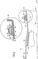
- the figure 2 shows a fan casing profile 100 made of composite material as it can be obtained by a method according to the invention.
- the inner surface 101 of the casing defines the air inlet vein. It may be provided with an abradable coating layer 102 in line with the trajectory of the tips of the blades of the fan, a blade 13 being partially shown very schematically.
- the abradable coating is therefore arranged over only part of the length (in the axial direction) of the casing.
- An acoustic treatment coating (not shown) can also be placed on the internal surface 101, in particular upstream of the abradable coating 102.
- the casing 100 can be provided with external flanges 104, 105 at its upstream and downstream ends in order to allow its assembly and its connection with other elements. Between its upstream and downstream ends, the casing 100 has a variable thickness, a portion of extra thickness 110 of the casing having a greater thickness than the structural parts 120 and 130.
- the extra thickness portion 110 extends on either side of the location of the fan, upstream and downstream, in order to form a retention zone or shield capable of retaining debris, particles or objects ingested at the inlet of the engine, or coming from the damage of the fan blades, and projected radially by rotation of the fan, to prevent them from crossing the casing and damaging other parts of the aircraft.
- the casing 100 is made of composite material with fibrous reinforcement densified by a matrix.
- the reinforcement is made of fibers, for example carbon, glass, aramid or ceramic
- the matrix is made of polymer, for example epoxy, bismaleimide or polyimide, carbon or ceramic.
- the fibrous reinforcement is formed by winding on a mandrel a fibrous texture produced by three-dimensional weaving with varying thickness, the mandrel having a profile corresponding to that of the casing to be produced.
- the fiber reinforcement constitutes a complete tubular fiber preform of the casing 100 forming a single piece with reinforcement parts corresponding to the flanges 104, 105.
- the fibrous reinforcement of the casing 100 consists of a plurality of superimposed layers of a fibrous texture in the form of a strip having a three-dimensional or multilayer weave, each layer corresponding to a winding turn of the fibrous texture.
- the fibrous reinforcement of the casing 100 consists of four superimposed layers or turns 141 to 144 of a fibrous texture 140, the layers or turns 141, 142, 143 and 144 corresponding respectively to the first, second, third and fourth winding turns of the fibrous texture 140 (on the figure 2 layers 141 to 144 are densified by a matrix).
- a stiffening element 150 is interposed between the penultimate turn and the last winding turn, here between the layer 143 and the layer 144.
- the element 150 having a width l 150 less than the width l 140 of the fibrous texture 140 and delimiting the retention zone of the casing 100.
- the stiffening element 150 protrudes from the outer surface 143a of the penultimate turn corresponding to the layer 143 of the fibrous texture 140, the stiffening element being covered by the fourth and last winding turn corresponding to the layer 144 of the fibrous texture 140.
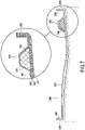
- the stiffening element 150 extends over a length L 150 corresponding to the circumference of the penultimate winding turn, i.e. the length of the third layer 143 ( figure 5 ).
- the stiffening element 150 has, in axial section, an omega or ⁇ type shape.
- the term “omega-type” shape is understood here to mean any element having a section having an omega or ⁇ shape.
- a stiffening element is directly integrated into the structure of the casing during its manufacture, the stiffening element being covered by the last turn of winding and, consequently, isolated from the external environment.
- fixing the stiffener element(s) to the surface of the casing requires the use of fixing means, for example gluing and/or bolted connection, which can increase the overall mass of the casing and whose reliability must be ensured for avoid the detachment of the stiffening element(s) present on the surface of the casing.
- fixing means for example gluing and/or bolted connection, which can increase the overall mass of the casing and whose reliability must be ensured for avoid the detachment of the stiffening element(s) present on the surface of the casing.
- each stiffener element is held in position very reliably because it is covered and retained by the last winding turn.
- the stiffening element can take different forms, such as for example a continuous strip or a plurality of segments added end to end as the winding progresses.
- the stiffening element has an omega-type shape in axial section.
- the integration of a distinct stiffening element between layers of fibrous texture makes it possible to obtain very steep slopes with respect to the axis X 100 of the casing 100.
- the angles ⁇ 151 and ⁇ 152 formed respectively between the side walls 151 and 152 of the stiffening element 150 and the axis X 100 of the casing 100 are preferably between 50° and 85°. These angles are defined in particular according to the stiffness which it is desired to impart to the casing and the manufacturing possibilities.
- the dimensioning (height, width, etc.) and the geometry of each stiffening element are defined according to the casing stiffening requirements (natural frequency).
- honeycomb structure made of a composite material chemically compatible with the resin of the matrix may in particular be a Nomex ® honeycomb from Hexcel ® .
- the stiffening element preferably has rounded edges, such as the edges 153 and 154 of the stiffening element 150, so as not to damage the fibrous texture by shearing the yarns or strands thereof for example.
- the edges or sharp corners present on each stiffening element can be machined in order to give them a rounded or soft shape.
- a fibrous texture 140 is produced in a known manner by weaving using a jacquard-type loom 10 on which a bundle of warp yarns or strands 20 has been placed in a plurality of layers, the warp yarns being bonded by weft threads or strands 30.
- the fibrous texture is produced by three-dimensional weaving.
- three-dimensional weaving or “3D weaving” is meant here a mode of weaving by which at least some of the weft yarns bind warp yarns over several layers of warp yarns or vice versa.
- An example of three-dimensional weaving is the so-called “interlock” weave.
- interlock weaving we mean here a weave of weaving in which each layer of warp threads binds several layers of weft threads with all the threads of the same column of warp having the same movement in the plane of the weave.
- Other known types of multilayer weaving may be used, such as in particular those described in the document WO 2006/136755 .
- the fibrous texture 140 has the form of a strip which extends lengthwise in a direction X corresponding to the running direction of the warp yarns or strands 20 and in width or transversely in a Y direction corresponding to the direction of the yarns or strands frame 30.
- the fibrous structure may in particular be woven from yarns of carbon fibers, ceramic fibers such as silicon carbide, glass, or even aramid.
- a fibrous preform is formed by winding on a mandrel 200 in a winding direction SR of the fibrous texture 140 produced by three-dimensional weaving, the mandrel having a profile corresponding to that of the casing to be produced.
- the fibrous preform constitutes a complete tubular fibrous reinforcement of the casing 100 forming a single piece with a portion of extra thickness corresponding to the retention zone of the casing.
- the mandrel 200 has an outer surface 201 whose profile corresponds to the inner surface of the casing to be produced. By its winding on the mandrel 200, the fibrous texture 140 matches the profile of the latter.
- the mandrel 200 also comprises two flanges 220 and 230 to form parts of the fibrous preform corresponding to the flanges 104 and 105 of the casing 100.
- a stiffening element 150 is inserted into the winding so as to be interposed between the penultimate turn and the last turn of the fibrous texture. as shown on the figure 5 .
- the stiffening element is positioned above the third layer 143 of the texture 140 so as to be covered by the last layer 144 of the fibrous texture 140.
- the figure 7 shows a sectional view of the fiber preform 300 obtained after winding the fiber texture 140 into several layers on the mandrel 200 and interposition of the stiffening element 150 between the penultimate layer and the last layer.
- the number of layers or turns depends on the desired thickness and the thickness of the fibrous texture. It is at least equal to 2.
- the preform 300 comprises 4 layers 141 to 144 of fibrous texture 140 and a stiffening element 150 interposed between the layers 143 and 144 corresponding respectively to the penultimate turn and the last turn of the winding.
- a fibrous preform 300 is obtained with a stiffening portion 350 formed by interposing the stiffening element between the layers 143 and 144.
- the fibrous preform 300 also comprises a portion of extra thickness 310 intended to form the zone or retention shield 110 of the casing , the gradual increase/decrease in thickness is obtained by adding/removing one or more layers of warp and weft yarns as described in particular in the document EP 1 961 923 .
- the fibrous preform 300 here again comprises end portions 320, 330 corresponding to the flanges 104, 105 of the casing.
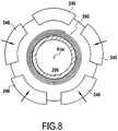
- the fibrous preform 300 is then densified with a matrix.
- the densification of the fibrous preform consists in filling the porosity of the preform, in all or part of the volume thereof, with the material constituting the matrix.
- the matrix can be obtained in a manner known per se using the liquid process.
- the liquid method consists in impregnating the preform with a liquid composition containing an organic precursor of the material of the matrix.
- the organic precursor usually comes in the form of a polymer, such as a resin, optionally diluted in a solvent.
- the fibrous preform is placed in a sealable mold with a housing having the shape of the final molded part.
- the fiber preform 300 is here placed between a plurality of sectors 240 forming the counter-mold and the mandrel 200 forming the support, these elements having respectively the outer shape and the inner shape of the casing to be produced.
- the liquid matrix precursor for example a resin, is injected into the entire housing to impregnate the entire fibrous part of the preform.
- the airy material is preferably impermeable to the resin so as not to weigh down the final part.
- the resin comprises closed cells or microbeads.
- the walls of the structure are impermeable to the resin.
- the transformation of the precursor into an organic matrix is carried out by heat treatment, generally by heating the mould, after removal of any solvent and crosslinking of the polymer, the preform still being maintained in the mold having a shape corresponding to that of the part to be made.
- the organic matrix can in particular be obtained from epoxy resins, such as, for example, the high-performance epoxy resin sold, or from liquid precursors of carbon or ceramic matrices.
- the heat treatment consists in pyrolyzing the organic precursor to transform the organic matrix into a carbon or ceramic matrix depending on the precursor used and the pyrolysis conditions.
- liquid carbon precursors can be resins with a relatively high coke content, such as phenolic resins
- liquid ceramic precursors, in particular of SiC can be resins of the polycarbosilane (PCS) type. or polytitanocarbosilane (PTCS) or polysilazane (PSZ).
- PCS polycarbosilane
- PTCS polytitanocarbosilane
- PSZ polysilazane
- the densification of the fiber preform can be carried out by the well-known process of transfer molding called RTM (“Resin Transfer Moulding”).
- RTM Resin Transfer Moulding
- the fiber preform is placed in a mold having the shape of the casing to be produced.
- a thermosetting resin is injected into the internal space delimited between the mandrel 200 and the counter-molds 240.
- a pressure gradient is generally established in this internal space between the place where the resin is injected and the evacuation orifices of this last in order to control and optimize the impregnation of the preform by the resin.
- the resin used can be, for example, an epoxy resin.
- Resins suitable for RTM processes are well known. They preferably have a low viscosity to facilitate their injection into the fibers. The choice of the temperature class and/or the chemical nature of the resin is determined according to the thermomechanical stresses to which the part must be subjected. Once the resin has been injected into the entire reinforcement, it is polymerized by heat treatment in accordance with the RTM process.
- the part After injection and polymerization, the part is demolded. In the end, the part is trimmed to remove the excess resin and the chamfers are machined to obtain the housing 100 illustrated in figure 1 and 2 .
- the casing 100 comprises a single stiffening element 150 present between the extra thickness portion 110 and the downstream flange 105.
- the casing according to the invention may comprise a stiffening element present between the upstream flange 104 and the extra thickness portion 110.
- the casing according to the invention may comprise a first stiffening element present between the upstream flange 104 and the extra thickness portion 110 and a second stiffening element present between the extra thickness portion 110 and the downstream flange 105.
- the stiffening element or elements integrated into the fibrous reinforcement of the casing it is possible to reduce the size or the title of the yarns or warp strands in the last layer or last turn of the fibrous texture at least at the level of the zone located above the stiffening element or elements, that is to say the part of the last turn of the fibrous texture covering the stiffening element or elements.
- the warp yarns or strands present in the fourth and last layer 144 of the fibrous texture 140 at the level of a zone Z R have a size or a count less than the size or the count of the warp yarns of the plurality of layers of warp threads present in the other turns of the fibrous texture.
- variable titer namely yarns or strands formed from a separable assembly of unitary yarns each having a determined titer such as those described in particular in the document EP 2 791 406 .
- the size or the count of the warp threads can be reduced when they enter the last round of winding by removing one or more individual threads from the variable count threads at the level of the zone concerned.
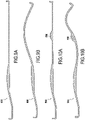
- the figures 9A and 9B show a fan casing made of composite material 400 according to the prior art, that is to say without integration of a stiffening element in the fiber reinforcement of the casing.
- the figure 9A represents the crankcase 400 at rest while the Figure 9B shows the deformation of the casing 400 simulated by calculation during an excitation of the latter by dynamic stressing of the fan blades in operation.
- the fan casing 400 has a mass M 400 and a natural frequency F 400 .
- the figures 10A and 10B show a fan casing made of composite material 500 according to the invention, that is to say with integration of a stiffening element 550 in the fiber reinforcement of the casing.
- the figure 10A represents the crankcase 500 at rest while the figure 10B shows the deformation of the casing 500 simulated by calculation during an excitation of the latter by dynamic stressing of the fan blades in operation.
- the fan casing 500 has a mass Msoo less than the mass M 400 of the casing 400 thanks to the integration of the stiffening element 550 which makes it possible to thin the casing in the area integrating the stiffener 550, for example by reducing the size or count of the warp threads in this zone and using a honeycomb structure for the stiffening element as described previously.
- the deformation simulation calculation shows that the casing 500 has a natural frequency F 500 which is greater than the natural frequency F 400 of the casing 400 according to the prior art. Consequently, by integrating at least one stiffening element in the fibrous reinforcement of the casing in accordance with the present invention, it is possible to reduce the overall mass of the casing made of composite material while increasing the natural frequency of the latter, which demonstrates the increase in stiffness provided by the stiffening element.
Landscapes
- Engineering & Computer Science (AREA)
- Mechanical Engineering (AREA)
- Chemical & Material Sciences (AREA)
- Composite Materials (AREA)
- Textile Engineering (AREA)
- General Engineering & Computer Science (AREA)
- Woven Fabrics (AREA)
- Moulding By Coating Moulds (AREA)
Applications Claiming Priority (2)
| Application Number | Priority Date | Filing Date | Title |
|---|---|---|---|
| FR1857963A FR3085299B1 (fr) | 2018-09-05 | 2018-09-05 | Carter en materiau composite avec raidisseur integre |
| PCT/FR2019/052031 WO2020049254A1 (fr) | 2018-09-05 | 2019-09-03 | Carter en materiau composite avec raidisseur integre |
Publications (2)
| Publication Number | Publication Date |
|---|---|
| EP3847006A1 EP3847006A1 (fr) | 2021-07-14 |
| EP3847006B1 true EP3847006B1 (fr) | 2022-08-24 |
Family
ID=65201285
Family Applications (1)
| Application Number | Title | Priority Date | Filing Date |
|---|---|---|---|
| EP19783584.6A Active EP3847006B1 (fr) | 2018-09-05 | 2019-09-03 | Carter en materiau composite avec raidisseur integre |
Country Status (5)
| Country | Link |
|---|---|
| US (1) | US11891910B2 (zh) |
| EP (1) | EP3847006B1 (zh) |
| CN (1) | CN112739530B (zh) |
| FR (1) | FR3085299B1 (zh) |
| WO (1) | WO2020049254A1 (zh) |
Families Citing this family (1)
| Publication number | Priority date | Publication date | Assignee | Title |
|---|---|---|---|---|
| FR3120878B1 (fr) * | 2021-03-17 | 2023-03-31 | Safran | Procédé de fabrication d’une pièce de turbomachine en matériau composite comportant une zone de rigidification |
Family Cites Families (19)
| Publication number | Priority date | Publication date | Assignee | Title |
|---|---|---|---|---|
| FR2887601B1 (fr) | 2005-06-24 | 2007-10-05 | Snecma Moteurs Sa | Piece mecanique et procede de fabrication d'une telle piece |
| US8475895B2 (en) * | 2006-11-21 | 2013-07-02 | General Electric Company | Articles comprising composite structures having mounting flanges |
| FR2913053B1 (fr) | 2007-02-23 | 2009-05-22 | Snecma Sa | Procede de fabrication d'un carter de turbine a gaz en materiau composite et carter ainsi obtenu |
| US8757958B2 (en) * | 2009-08-31 | 2014-06-24 | United Technologies Corporation | Composite fan containment case |
| EP2524134B1 (en) * | 2010-01-14 | 2014-05-07 | Neptco, Inc. | Wind turbine rotor blade components and methods of making same |
| US8499450B2 (en) * | 2010-01-26 | 2013-08-06 | United Technologies Corporation | Three-dimensionally woven composite blade with spanwise weft yarns |
| FR2966508B1 (fr) * | 2010-10-22 | 2015-04-03 | Snecma | Carter de soufflante de moteur aeronautique en materiau composite et procede pour sa fabrication |
| FR2975735A1 (fr) * | 2011-05-27 | 2012-11-30 | Snecma | Carter de soufflante de turbomachine et procede pour sa fabrication |
| FR2977827B1 (fr) * | 2011-07-13 | 2015-03-13 | Snecma | Procede de fabrication d'un carter de soufflante de turbomachine muni de revetements abradable et acoustique |
| FR2983428B1 (fr) * | 2011-12-01 | 2014-01-17 | Snecma Propulsion Solide | Procede de fabrication d'une aube de turbomachine en materiau composite a plates-formes integrees |
| EP2791406B1 (fr) | 2011-12-14 | 2016-10-12 | SNECMA Services | Structure fibreuse avec fils a titre variable |
| FR3031469B1 (fr) * | 2015-01-14 | 2017-09-22 | Snecma | Carter en materiau composite a matrice organique auto-raidi |
| FR3033839B1 (fr) | 2015-03-16 | 2018-09-28 | Safran Aircraft Engines | Ensemble pour turbomachine d'aeronef comprenant un carter de soufflante equipe d'un revetement acoustique integrant un raidisseur de carter de soufflante |
| FR3035675B1 (fr) * | 2015-04-29 | 2017-05-12 | Snecma | Aube munie de plateformes comportant des inserts |
| WO2017109403A1 (fr) * | 2015-12-22 | 2017-06-29 | Safran Aircraft Engines | Carter allégé en matériau composite et son procédé de fabrication |
| FR3045448B1 (fr) * | 2015-12-22 | 2018-01-26 | Safran Aircraft Engines | Carter allege en materiau composite et son procede de fabrication |
| FR3045456B1 (fr) * | 2015-12-22 | 2020-10-23 | Snecma | Carter allege en materiau composite et son procede de fabrication |
| FR3074088B1 (fr) * | 2017-11-30 | 2021-02-12 | Safran Aircraft Engines | Carter en materiau composite renforce et son procede de fabrication |
| US11078839B2 (en) * | 2018-01-22 | 2021-08-03 | Rolls-Royce Corporation | Composite nosecone |
-
2018
- 2018-09-05 FR FR1857963A patent/FR3085299B1/fr active Active
-
2019
- 2019-09-03 WO PCT/FR2019/052031 patent/WO2020049254A1/fr unknown
- 2019-09-03 CN CN201980058760.9A patent/CN112739530B/zh active Active
- 2019-09-03 US US17/273,528 patent/US11891910B2/en active Active
- 2019-09-03 EP EP19783584.6A patent/EP3847006B1/fr active Active
Also Published As
| Publication number | Publication date |
|---|---|
| US11891910B2 (en) | 2024-02-06 |
| EP3847006A1 (fr) | 2021-07-14 |
| WO2020049254A1 (fr) | 2020-03-12 |
| FR3085299A1 (fr) | 2020-03-06 |
| FR3085299B1 (fr) | 2021-04-16 |
| US20210340881A1 (en) | 2021-11-04 |
| CN112739530A (zh) | 2021-04-30 |
| CN112739530B (zh) | 2022-09-23 |
Similar Documents
| Publication | Publication Date | Title |
|---|---|---|
| EP3183111B1 (fr) | Carter en materiau composite a matrice organique et son procede de fabrication | |
| EP3393764B1 (fr) | Carter allégé en matériau composite et son procédé de fabrication | |
| EP1961923B1 (fr) | Procédé de fabrication d'un carter de turbine à gaz en matériau composite et carter ainsi obtenu. | |
| EP3827119B1 (fr) | Texture fibreuse pour carter en matériau composite à résistance à l'impact améliorée | |
| WO2013007937A2 (fr) | Procede de fabrication d'un carter de soufflante de turbomachine muni de revetement acoustique. | |
| EP3927529B1 (fr) | Reparation ou reprise de fabrication d'une piece en materiau composite a renfort fibreux tisse tridimensionnel | |
| FR3074088A1 (fr) | Carter en materiau composite renforce et son procede de fabrication | |
| EP3676431B1 (fr) | Texture fibreuse tissee pour la formation d'une preforme de carter | |
| EP3453847B1 (fr) | Carter en matériau composite à géométrie raidissante | |
| FR3045448A1 (fr) | Carter allege en materiau composite et son procede de fabrication | |
| WO2020178500A1 (fr) | Reparation ou reprise de fabrication d' une piece en materiau composite | |
| FR3059044A1 (fr) | Carter de soufflante de turbomachine aeronautique | |
| FR3045456A1 (fr) | Carter allege en materiau composite et son procede de fabrication | |
| EP3847006B1 (fr) | Carter en materiau composite avec raidisseur integre | |
| EP3827118B1 (fr) | Texture fibreuse pour carter en matériau composite à résistance au cisaillement ameliorée | |
| FR3066715A1 (fr) | Texture fibreuse destinee a la fabrication d'un carter de moteur aeronautique | |
| EP3917762B1 (fr) | Carter en matériau composite avec variation locale d'épaisseur | |
| FR3141637A1 (fr) | Texture fibreuse pour carter en matériau composite auto-raidi | |
| WO2023194692A1 (fr) | Pièce de révolution en matériau composite a capacité de rétention améliorée | |
| WO2024100357A1 (fr) | Texture fibreuse pour carter en materiau composite aux brides renforcees. |
Legal Events
| Date | Code | Title | Description |
|---|---|---|---|
| STAA | Information on the status of an ep patent application or granted ep patent |
Free format text: STATUS: UNKNOWN |
|
| STAA | Information on the status of an ep patent application or granted ep patent |
Free format text: STATUS: THE INTERNATIONAL PUBLICATION HAS BEEN MADE |
|
| PUAI | Public reference made under article 153(3) epc to a published international application that has entered the european phase |
Free format text: ORIGINAL CODE: 0009012 |
|
| STAA | Information on the status of an ep patent application or granted ep patent |
Free format text: STATUS: REQUEST FOR EXAMINATION WAS MADE |
|
| 17P | Request for examination filed |
Effective date: 20210331 |
|
| AK | Designated contracting states |
Kind code of ref document: A1 Designated state(s): AL AT BE BG CH CY CZ DE DK EE ES FI FR GB GR HR HU IE IS IT LI LT LU LV MC MK MT NL NO PL PT RO RS SE SI SK SM TR |
|
| DAV | Request for validation of the european patent (deleted) | ||
| DAX | Request for extension of the european patent (deleted) | ||
| GRAP | Despatch of communication of intention to grant a patent |
Free format text: ORIGINAL CODE: EPIDOSNIGR1 |
|
| STAA | Information on the status of an ep patent application or granted ep patent |
Free format text: STATUS: GRANT OF PATENT IS INTENDED |
|
| RIC1 | Information provided on ipc code assigned before grant |
Ipc: B29C 70/86 20060101ALI20220319BHEP Ipc: B29L 31/00 20060101ALI20220319BHEP Ipc: B29C 70/32 20060101ALI20220319BHEP Ipc: F01D 25/24 20060101ALI20220319BHEP Ipc: B29C 70/24 20060101AFI20220319BHEP |
|
| INTG | Intention to grant announced |
Effective date: 20220420 |
|
| GRAS | Grant fee paid |
Free format text: ORIGINAL CODE: EPIDOSNIGR3 |
|
| GRAA | (expected) grant |
Free format text: ORIGINAL CODE: 0009210 |
|
| STAA | Information on the status of an ep patent application or granted ep patent |
Free format text: STATUS: THE PATENT HAS BEEN GRANTED |
|
| AK | Designated contracting states |
Kind code of ref document: B1 Designated state(s): AL AT BE BG CH CY CZ DE DK EE ES FI FR GB GR HR HU IE IS IT LI LT LU LV MC MK MT NL NO PL PT RO RS SE SI SK SM TR |
|
| REG | Reference to a national code |
Ref country code: CH Ref legal event code: EP |
|
| REG | Reference to a national code |
Ref country code: IE Ref legal event code: FG4D Free format text: LANGUAGE OF EP DOCUMENT: FRENCH |
|
| REG | Reference to a national code |
Ref country code: AT Ref legal event code: REF Ref document number: 1513358 Country of ref document: AT Kind code of ref document: T Effective date: 20220915 Ref country code: DE Ref legal event code: R096 Ref document number: 602019018739 Country of ref document: DE |
|
| REG | Reference to a national code |
Ref country code: LT Ref legal event code: MG9D |
|
| REG | Reference to a national code |
Ref country code: NL Ref legal event code: MP Effective date: 20220824 |
|
| PG25 | Lapsed in a contracting state [announced via postgrant information from national office to epo] |
Ref country code: SE Free format text: LAPSE BECAUSE OF FAILURE TO SUBMIT A TRANSLATION OF THE DESCRIPTION OR TO PAY THE FEE WITHIN THE PRESCRIBED TIME-LIMIT Effective date: 20220824 Ref country code: RS Free format text: LAPSE BECAUSE OF FAILURE TO SUBMIT A TRANSLATION OF THE DESCRIPTION OR TO PAY THE FEE WITHIN THE PRESCRIBED TIME-LIMIT Effective date: 20220824 Ref country code: PT Free format text: LAPSE BECAUSE OF FAILURE TO SUBMIT A TRANSLATION OF THE DESCRIPTION OR TO PAY THE FEE WITHIN THE PRESCRIBED TIME-LIMIT Effective date: 20221226 Ref country code: NO Free format text: LAPSE BECAUSE OF FAILURE TO SUBMIT A TRANSLATION OF THE DESCRIPTION OR TO PAY THE FEE WITHIN THE PRESCRIBED TIME-LIMIT Effective date: 20221124 Ref country code: NL Free format text: LAPSE BECAUSE OF FAILURE TO SUBMIT A TRANSLATION OF THE DESCRIPTION OR TO PAY THE FEE WITHIN THE PRESCRIBED TIME-LIMIT Effective date: 20220824 Ref country code: LV Free format text: LAPSE BECAUSE OF FAILURE TO SUBMIT A TRANSLATION OF THE DESCRIPTION OR TO PAY THE FEE WITHIN THE PRESCRIBED TIME-LIMIT Effective date: 20220824 Ref country code: LT Free format text: LAPSE BECAUSE OF FAILURE TO SUBMIT A TRANSLATION OF THE DESCRIPTION OR TO PAY THE FEE WITHIN THE PRESCRIBED TIME-LIMIT Effective date: 20220824 Ref country code: FI Free format text: LAPSE BECAUSE OF FAILURE TO SUBMIT A TRANSLATION OF THE DESCRIPTION OR TO PAY THE FEE WITHIN THE PRESCRIBED TIME-LIMIT Effective date: 20220824 |
|
| REG | Reference to a national code |
Ref country code: AT Ref legal event code: MK05 Ref document number: 1513358 Country of ref document: AT Kind code of ref document: T Effective date: 20220824 |
|
| PG25 | Lapsed in a contracting state [announced via postgrant information from national office to epo] |
Ref country code: PL Free format text: LAPSE BECAUSE OF FAILURE TO SUBMIT A TRANSLATION OF THE DESCRIPTION OR TO PAY THE FEE WITHIN THE PRESCRIBED TIME-LIMIT Effective date: 20220824 Ref country code: IS Free format text: LAPSE BECAUSE OF FAILURE TO SUBMIT A TRANSLATION OF THE DESCRIPTION OR TO PAY THE FEE WITHIN THE PRESCRIBED TIME-LIMIT Effective date: 20221224 Ref country code: HR Free format text: LAPSE BECAUSE OF FAILURE TO SUBMIT A TRANSLATION OF THE DESCRIPTION OR TO PAY THE FEE WITHIN THE PRESCRIBED TIME-LIMIT Effective date: 20220824 Ref country code: GR Free format text: LAPSE BECAUSE OF FAILURE TO SUBMIT A TRANSLATION OF THE DESCRIPTION OR TO PAY THE FEE WITHIN THE PRESCRIBED TIME-LIMIT Effective date: 20221125 |
|
| PG25 | Lapsed in a contracting state [announced via postgrant information from national office to epo] |
Ref country code: SM Free format text: LAPSE BECAUSE OF FAILURE TO SUBMIT A TRANSLATION OF THE DESCRIPTION OR TO PAY THE FEE WITHIN THE PRESCRIBED TIME-LIMIT Effective date: 20220824 Ref country code: RO Free format text: LAPSE BECAUSE OF FAILURE TO SUBMIT A TRANSLATION OF THE DESCRIPTION OR TO PAY THE FEE WITHIN THE PRESCRIBED TIME-LIMIT Effective date: 20220824 Ref country code: ES Free format text: LAPSE BECAUSE OF FAILURE TO SUBMIT A TRANSLATION OF THE DESCRIPTION OR TO PAY THE FEE WITHIN THE PRESCRIBED TIME-LIMIT Effective date: 20220824 Ref country code: DK Free format text: LAPSE BECAUSE OF FAILURE TO SUBMIT A TRANSLATION OF THE DESCRIPTION OR TO PAY THE FEE WITHIN THE PRESCRIBED TIME-LIMIT Effective date: 20220824 Ref country code: CZ Free format text: LAPSE BECAUSE OF FAILURE TO SUBMIT A TRANSLATION OF THE DESCRIPTION OR TO PAY THE FEE WITHIN THE PRESCRIBED TIME-LIMIT Effective date: 20220824 Ref country code: AT Free format text: LAPSE BECAUSE OF FAILURE TO SUBMIT A TRANSLATION OF THE DESCRIPTION OR TO PAY THE FEE WITHIN THE PRESCRIBED TIME-LIMIT Effective date: 20220824 |
|
| REG | Reference to a national code |
Ref country code: CH Ref legal event code: PL |
|
| REG | Reference to a national code |
Ref country code: DE Ref legal event code: R097 Ref document number: 602019018739 Country of ref document: DE Ref country code: BE Ref legal event code: MM Effective date: 20220930 |
|
| PG25 | Lapsed in a contracting state [announced via postgrant information from national office to epo] |
Ref country code: SK Free format text: LAPSE BECAUSE OF FAILURE TO SUBMIT A TRANSLATION OF THE DESCRIPTION OR TO PAY THE FEE WITHIN THE PRESCRIBED TIME-LIMIT Effective date: 20220824 Ref country code: MC Free format text: LAPSE BECAUSE OF FAILURE TO SUBMIT A TRANSLATION OF THE DESCRIPTION OR TO PAY THE FEE WITHIN THE PRESCRIBED TIME-LIMIT Effective date: 20220824 Ref country code: EE Free format text: LAPSE BECAUSE OF FAILURE TO SUBMIT A TRANSLATION OF THE DESCRIPTION OR TO PAY THE FEE WITHIN THE PRESCRIBED TIME-LIMIT Effective date: 20220824 |
|
| PG25 | Lapsed in a contracting state [announced via postgrant information from national office to epo] |
Ref country code: LU Free format text: LAPSE BECAUSE OF NON-PAYMENT OF DUE FEES Effective date: 20220903 Ref country code: AL Free format text: LAPSE BECAUSE OF FAILURE TO SUBMIT A TRANSLATION OF THE DESCRIPTION OR TO PAY THE FEE WITHIN THE PRESCRIBED TIME-LIMIT Effective date: 20220824 |
|
| PLBE | No opposition filed within time limit |
Free format text: ORIGINAL CODE: 0009261 |
|
| STAA | Information on the status of an ep patent application or granted ep patent |
Free format text: STATUS: NO OPPOSITION FILED WITHIN TIME LIMIT |
|
| PG25 | Lapsed in a contracting state [announced via postgrant information from national office to epo] |
Ref country code: LI Free format text: LAPSE BECAUSE OF NON-PAYMENT OF DUE FEES Effective date: 20220930 Ref country code: IE Free format text: LAPSE BECAUSE OF NON-PAYMENT OF DUE FEES Effective date: 20220903 Ref country code: CH Free format text: LAPSE BECAUSE OF NON-PAYMENT OF DUE FEES Effective date: 20220930 |
|
| 26N | No opposition filed |
Effective date: 20230525 |
|
| PG25 | Lapsed in a contracting state [announced via postgrant information from national office to epo] |
Ref country code: SI Free format text: LAPSE BECAUSE OF FAILURE TO SUBMIT A TRANSLATION OF THE DESCRIPTION OR TO PAY THE FEE WITHIN THE PRESCRIBED TIME-LIMIT Effective date: 20220824 |
|
| PG25 | Lapsed in a contracting state [announced via postgrant information from national office to epo] |
Ref country code: BE Free format text: LAPSE BECAUSE OF NON-PAYMENT OF DUE FEES Effective date: 20220930 |
|
| PGFP | Annual fee paid to national office [announced via postgrant information from national office to epo] |
Ref country code: GB Payment date: 20230823 Year of fee payment: 5 |
|
| PGFP | Annual fee paid to national office [announced via postgrant information from national office to epo] |
Ref country code: FR Payment date: 20230822 Year of fee payment: 5 Ref country code: DE Payment date: 20230822 Year of fee payment: 5 |
|
| PG25 | Lapsed in a contracting state [announced via postgrant information from national office to epo] |
Ref country code: CY Free format text: LAPSE BECAUSE OF FAILURE TO SUBMIT A TRANSLATION OF THE DESCRIPTION OR TO PAY THE FEE WITHIN THE PRESCRIBED TIME-LIMIT Effective date: 20220824 |