EP3846709B1 - Prüfsystem für elektrochirurgischen generator - Google Patents
Prüfsystem für elektrochirurgischen generator Download PDFInfo
- Publication number
- EP3846709B1 EP3846709B1 EP19772930.4A EP19772930A EP3846709B1 EP 3846709 B1 EP3846709 B1 EP 3846709B1 EP 19772930 A EP19772930 A EP 19772930A EP 3846709 B1 EP3846709 B1 EP 3846709B1
- Authority
- EP
- European Patent Office
- Prior art keywords
- generator
- electrosurgical
- self
- verification
- verification system
- Prior art date
- Legal status (The legal status is an assumption and is not a legal conclusion. Google has not performed a legal analysis and makes no representation as to the accuracy of the status listed.)
- Active
Links
Images




Classifications
-
- A—HUMAN NECESSITIES
- A61—MEDICAL OR VETERINARY SCIENCE; HYGIENE
- A61B—DIAGNOSIS; SURGERY; IDENTIFICATION
- A61B18/00—Surgical instruments, devices or methods for transferring non-mechanical forms of energy to or from the body
- A61B18/04—Surgical instruments, devices or methods for transferring non-mechanical forms of energy to or from the body by heating
- A61B18/12—Surgical instruments, devices or methods for transferring non-mechanical forms of energy to or from the body by heating by passing a current through the tissue to be heated, e.g. high-frequency current
- A61B18/1206—Generators therefor
-
- A—HUMAN NECESSITIES
- A61—MEDICAL OR VETERINARY SCIENCE; HYGIENE
- A61B—DIAGNOSIS; SURGERY; IDENTIFICATION
- A61B18/00—Surgical instruments, devices or methods for transferring non-mechanical forms of energy to or from the body
- A61B18/04—Surgical instruments, devices or methods for transferring non-mechanical forms of energy to or from the body by heating
- A61B18/12—Surgical instruments, devices or methods for transferring non-mechanical forms of energy to or from the body by heating by passing a current through the tissue to be heated, e.g. high-frequency current
- A61B18/1206—Generators therefor
- A61B18/1233—Generators therefor with circuits for assuring patient safety
-
- A—HUMAN NECESSITIES
- A61—MEDICAL OR VETERINARY SCIENCE; HYGIENE
- A61B—DIAGNOSIS; SURGERY; IDENTIFICATION
- A61B18/00—Surgical instruments, devices or methods for transferring non-mechanical forms of energy to or from the body
- A61B18/04—Surgical instruments, devices or methods for transferring non-mechanical forms of energy to or from the body by heating
- A61B18/12—Surgical instruments, devices or methods for transferring non-mechanical forms of energy to or from the body by heating by passing a current through the tissue to be heated, e.g. high-frequency current
- A61B18/14—Probes or electrodes therefor
- A61B18/1442—Probes having pivoting end effectors, e.g. forceps
-
- A—HUMAN NECESSITIES
- A61—MEDICAL OR VETERINARY SCIENCE; HYGIENE
- A61B—DIAGNOSIS; SURGERY; IDENTIFICATION
- A61B18/00—Surgical instruments, devices or methods for transferring non-mechanical forms of energy to or from the body
- A61B2018/00571—Surgical instruments, devices or methods for transferring non-mechanical forms of energy to or from the body for achieving a particular surgical effect
- A61B2018/00601—Cutting
-
- A—HUMAN NECESSITIES
- A61—MEDICAL OR VETERINARY SCIENCE; HYGIENE
- A61B—DIAGNOSIS; SURGERY; IDENTIFICATION
- A61B18/00—Surgical instruments, devices or methods for transferring non-mechanical forms of energy to or from the body
- A61B2018/00571—Surgical instruments, devices or methods for transferring non-mechanical forms of energy to or from the body for achieving a particular surgical effect
- A61B2018/0063—Sealing
-
- A—HUMAN NECESSITIES
- A61—MEDICAL OR VETERINARY SCIENCE; HYGIENE
- A61B—DIAGNOSIS; SURGERY; IDENTIFICATION
- A61B18/00—Surgical instruments, devices or methods for transferring non-mechanical forms of energy to or from the body
- A61B2018/00636—Sensing and controlling the application of energy
- A61B2018/00898—Alarms or notifications created in response to an abnormal condition
-
- A—HUMAN NECESSITIES
- A61—MEDICAL OR VETERINARY SCIENCE; HYGIENE
- A61B—DIAGNOSIS; SURGERY; IDENTIFICATION
- A61B18/00—Surgical instruments, devices or methods for transferring non-mechanical forms of energy to or from the body
- A61B18/04—Surgical instruments, devices or methods for transferring non-mechanical forms of energy to or from the body by heating
- A61B18/12—Surgical instruments, devices or methods for transferring non-mechanical forms of energy to or from the body by heating by passing a current through the tissue to be heated, e.g. high-frequency current
- A61B18/1206—Generators therefor
- A61B2018/1246—Generators therefor characterised by the output polarity
- A61B2018/1253—Generators therefor characterised by the output polarity monopolar
-
- A—HUMAN NECESSITIES
- A61—MEDICAL OR VETERINARY SCIENCE; HYGIENE
- A61B—DIAGNOSIS; SURGERY; IDENTIFICATION
- A61B18/00—Surgical instruments, devices or methods for transferring non-mechanical forms of energy to or from the body
- A61B18/04—Surgical instruments, devices or methods for transferring non-mechanical forms of energy to or from the body by heating
- A61B18/12—Surgical instruments, devices or methods for transferring non-mechanical forms of energy to or from the body by heating by passing a current through the tissue to be heated, e.g. high-frequency current
- A61B18/1206—Generators therefor
- A61B2018/1246—Generators therefor characterised by the output polarity
- A61B2018/126—Generators therefor characterised by the output polarity bipolar
-
- A—HUMAN NECESSITIES
- A61—MEDICAL OR VETERINARY SCIENCE; HYGIENE
- A61B—DIAGNOSIS; SURGERY; IDENTIFICATION
- A61B18/00—Surgical instruments, devices or methods for transferring non-mechanical forms of energy to or from the body
- A61B18/04—Surgical instruments, devices or methods for transferring non-mechanical forms of energy to or from the body by heating
- A61B18/12—Surgical instruments, devices or methods for transferring non-mechanical forms of energy to or from the body by heating by passing a current through the tissue to be heated, e.g. high-frequency current
- A61B18/14—Probes or electrodes therefor
- A61B18/1442—Probes having pivoting end effectors, e.g. forceps
- A61B2018/1452—Probes having pivoting end effectors, e.g. forceps including means for cutting
- A61B2018/1455—Probes having pivoting end effectors, e.g. forceps including means for cutting having a moving blade for cutting tissue grasped by the jaws
-
- A—HUMAN NECESSITIES
- A61—MEDICAL OR VETERINARY SCIENCE; HYGIENE
- A61B—DIAGNOSIS; SURGERY; IDENTIFICATION
- A61B2560/00—Constructional details of operational features of apparatus; Accessories for medical measuring apparatus
- A61B2560/02—Operational features
- A61B2560/0266—Operational features for monitoring or limiting apparatus function
- A61B2560/0276—Determining malfunction
Definitions
- the present disclosure is directed to electrosurgical generator systems having output verification of electrosurgical generators configured to supply radiofrequency (RF) energy.
- RF radiofrequency
- Electrosurgical devices or instruments have become available that use radiofrequency (RF) energy to perform certain surgical tasks such as coagulate, fuse, or cut tissue.
- RF radiofrequency
- Such electrosurgical instruments typically fall within two classifications: monopolar and bipolar.
- monopolar instruments electrical energy is supplied to one or more electrodes on the instrument with high current density while a separate return electrode is electrically coupled to a patient and is often designed to minimize current density.
- Bipolar electrosurgical instruments which operate without separate return electrodes, can deliver electrical signals to a focused tissue area with reduced risks.
- an electrosurgical system as recited in claim 1 for sealing, fusing and/or cutting tissue.
- This disclosure relates in general to electrosurgical systems. It specifically relates to a new generation of electrosurgical generators capable of initiating and performing an auto-verification and self-verification system test of the generators.
- verification of the generator's output is often required to ensure the RF being outputted from the generator is as intended. This verification can be performed periodically, e.g., every twelve months or two years and often by a user interactive or manual system or process.
- the system or process may also require the connection of various external devices to the generator. These external devices may include a verification adapter, external loads, e.g., 10-500 Ohm loads with decreasing power ratings and increasing voltage ratings, and/or measuring devices, e.g., oscilloscope, differential voltage probe and current probe.
- the user must then connect the appropriate adapter, loads and/or measuring devices and perform specified tests requiring adjustments to the generator, external devices and/or measuring devices and connections thereto. Additionally, appropriate monitoring and recording the test results are required along with understanding errors and physically removing a faulty generator from use. Also, to perform the generator's output verification, the generator must be taken out of circulation and not be used in a surgical procedure, and often times not performed at a surgical site such as, for example, hospitals, due to lack of experience, personnel or equipment.
- Embodiments of the present invention are directed to systems for enhancing surgical outcomes by providing generators having accurate RF energy generation, measurement, calibration and/or selftesting system.
- the present invention allows detection of failure, thereby reducing troubleshooting and surgical operational time while avoiding other potential surgical difficulties. This is achieved through implementation of an automated self-verification process after a predetermined amount of time after power start-up of the electrosurgical generator.
- the electrosurgical generators of electrosurgical systems include a plurality of switchable impedance loads for performing the self-verification process.
- the internal impedance load with multiple configurations are utilized to verify the voltage, current, power, and/or phase measurements of the generator.
- these improvements may include, but not limited to, elimination for connecting external devices to the generator, thereby removing the risk of using unavailable or unreliable test equipment, and/or unavailable or inexperienced personnel.
- the need for taking the generator out of circulation for performing the generator's output verification is completely eliminated.
- electrosurgical system according to various embodiments of the present invention is explained in detail with sections individually describing: the electrosurgical generator, the electrosurgical instrument and the control system and method used for performing the automated self-verification system test of the generator.
- an electrosurgical system having an electrosurgical generator that controls the delivery of electrosurgical or radiofrequency (RF) energy, adjusts the RF energy and in various embodiments measures and monitors electrical properties, e.g., phase, current, voltage and/or power, of the supplied RF energy to a connectable electrosurgical instrument to ensure optimal sealing, fusing and/or cutting of tissues or vessels.
- the generator may include a feedback system that determines such electrical properties and through a microcontroller regulates and/or controls an RF amplifier that generates the required RF energy to provide the optimal RF output for sealing, fusing and/or cutting tissue/vessels under dynamic conditions, such as for example, varying loads, procedural or operational conditions.
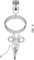
- the electrosurgical system may include an electrosurgical generator 10 and a removably connectable electrosurgical tool or instrument 20.
- the electrosurgical hand device or instrument 20 can be electrically coupled to the generator 10 via a cabled connection with a device key or connector 21 extending from the instrument 20 to a device connector or access port 12 on the generator 10.
- the electrosurgical instrument 20 may include audio, tactile and/or visual indicators to apprise a user of a particular or predetermined status of the instrument 20 such as, for example, a start and/or end of a fusion operation.
- a manual controller such as a hand or foot switch can be connectable to the generator 10 and/or instrument 20 to allow predetermined selective control of the instrument such as to commence a fusion operation.
- the generator 10 further includes a user-accessible power-on switch or button 18 that when activated powers the generator 10 and activates or initiates a self-verification system test of the generator.
- the display 14 can be a touch screen display thus integrating data display and user interface functionalities.
- the electrosurgical generator 10 of the present invention is configured to output radiofrequency (RF) energy through the connectable electrosurgical instrument or hand device 20 to seal, fuse and/or cut tissue or vessels via one or more electrodes.
- the electrosurgical generator 10, according to the embodiments of the present invention is configured to generate up to 300V, 8A, and 375VA of RF energy and it is also configured to determine a phase angle or difference between RF output voltage and RF output current of the generator during activation or supply of RF energy. In this way, the electrosurgical generator 10 regulates voltage, current and/or power and monitors RF energy output (e.g., voltage, current, power and/or phase). In one embodiment, the generator 10 may stop, terminate or otherwise disrupt RF energy output under predetermined conditions.
- RF radiofrequency
- these predetermined conditions may be any of the following conditions: when a device switch is deasserted (e.g., fuse button released), a time value is met, and/or active phase angle and/or change of phase is greater than or equal to a phase and/or change of phase stop value indicating end of an operation such as fusion or cutting of tissue.
- a device switch is deasserted (e.g., fuse button released)
- a time value is met
- active phase angle and/or change of phase is greater than or equal to a phase and/or change of phase stop value indicating end of an operation such as fusion or cutting of tissue.
- the electrosurgical instrument 20, may include an elongate shaft 26 having a proximal end coupled to or from which an actuator 24 extends and a distal end coupled to or from which jaws 22 extend. A longitudinal axis extending from the proximal end to the distal end of the elongate shaft 26.
- the actuator 24 may include a movable handle 23 which is pivotably coupled to a stationary handle or housing 28. The movable handle 23 is coupled to the stationary handle or housing 28 through a central or main floating pivot.
- the movable handle 23 is manipulated by a user, e.g., a surgeon, to actuate the jaws 22 at the distal end of the elongate shaft 26, and thereby, selectively opening and closing the jaws 22.
- a switch or button 29 is activated by the surgeon to seal, fuse and/or cut the tissue/vessels between the jaws 22.
- associated circuitry or contacts are connected to connect appropriate electrodes of the jaws with associated connections of the generator 10 to supply RF energy to tissue grasped between the jaws 22 or otherwise in contact with the one or more electrodes of the jaws.
- the electrosurgical instrument 20 further includes a mechanical or electrical cutting blade that can be coupled to a blade actuator such as a blade lever or trigger 25 of the stationary handle or housing 28.
- the cutting blade is actuated by the blade trigger 25 to divide or cut the tissue between the jaws 22.
- a blade slider is connected to the blade trigger 25 and a protrusion extends from a proximal portion of the blade slider into an opening in one end of the blade trigger connecting the components together.
- the other end of the blade trigger is exposed and accessible by the user with the blade trigger 25 being pivotable about a trigger pivot at or near the midpoint of the blade trigger.
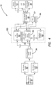
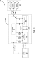
- the electrosurgical generator 10 may include a power entry module 31, e.g., an AC main input, coupled to a power supply module, e.g., two 48V DC power supplies 32, 33.
- the power supply module converts the AC voltage from the AC main input to a DC voltage and via a house keeping power supply 34 provides power to various circuitry of the generator 10 and in particular supplies power to an RF amplifier 40 that generates or outputs the RF energy.
- the RF amplifier 40 may include a combined Buck and H-Bridge circuitry to convert a DC voltage input into an RF output and in another embodiment into a variable amplitude 350kHz sine wave.
- the DC voltage input is a 96V DC input that is generated by the two 48V DC power supplies 32, 33 coupled in series.
- One of the 48V DC power supply 32, 33 is configured to generate low voltage rails and in particular supply standby voltage to power on the generator 10.
- the feedback system 60 measures the RF output and, after processing the measured data, digitally feeds the RF output's real and imaginary components to the primary microcontroller 50.
- the primary microcontroller 50 may include a primary field programmable gate array (FPGA) and a processor.
- the processor of the microcontroller 50 may include an advanced reduced instruction set machine (ARM) processor.
- the primary FPGA processes the received data from the feedback system 60 and adjusts the output of the RF amplifier 40 to meet a desired regulation target.
- the feedback system 60 comprises of analog input, digital processing and digital output.
- the verification system 60 may include a main channel 601 and a redundant channel 602.
- the main channel 601 and redundant channel 602 in various embodiments may include separate but identical components. Additionally, the main and redundant channels 601 and 602 follow separate but identical electrical paths and in one embodiment are both connected to the RF amplifier 40 and the RF output.
- the feedback system 60 further includes a verification channel 603 which in various embodiments is separate but similar to the main channel 601 and redundant channel 602.
- the verification channel 603 may include components that are separate from the other channels but are similar.
- the verification channel 603 may include the same components as the main and redundant channels 601 and 602, but the components in the verification channel 603 have higher ratings, e.g., higher resolution and/or lower drift, and are often more costly.
- the verification channel 603 may include the same components as the main and redundant channels 601 and 602. However, in various embodiments, the verification channel 603 is only used in the operation of or by the self-verification test system.
- the components of the verification channel 603 are used less often and thus may remain more accurate, e.g., have less drift, than the components of the main and/or redundant channels 601 and 602 that are constantly used throughout the generator's operations.
- the verification channel 603 follows a separate but identical electrical path as the main and redundant channels 601 and 602 and in one embodiment is connected to the RF amplifier 40 and the RF output.
- the channels 601, 602 and/or 603 in accordance with various embodiments comprises circuitry including active and/or passive components and electrical pathways connected thereto arranged to transmit and/or measure the RF energy supplied from the RF amplifier to the microcontroller and/or as directed by the microcontroller.
- one or more or all the channels includes and/or are connected to one or more measurement circuitry comprising sensors, detectors, comparators, resistors, memory and/or the like and/or any combination thereof configured to measure, calculate and/or record such measurements of electrical properties (e.g., current, voltage, power, and/or phase) of the RF energy directed across the one or more or all the channels.
- the electrosurgical generator 10 logs all RF output data onto an internal memory device, e.g., a secure digital (SD) or non-volatile memory card.
- the memory device is configured to be read through an interface port 35, e.g., a universal serial bus (USB) port, on the electrosurgical generator 10 (best shown in FIG. 4 ).
- the generator 10 is configured to copy the data from the internal memory device to a connectable portable storage device, e.g., a USB flash drive, through the interface port of the generator.
- the electrosurgical generator 10 is configured to alert the surgeon when the vessel has reached a completed procedure state, e.g., a completed seal state, or if an error or fault condition has occurred.
- the electrosurgical generator 10 in various embodiments may include visual, tactile and/or audible outputs to provide such alerts or other indicators or information to the surgeon as dictated by the surgical procedure, device script or health or operational information regarding the device 20 and/or generator 10.
- the generator 10 via a front panel interface 38 alerts the surgeon through the LCD display 14, which is integrated into a front panel of the generator, and in various embodiments provides specific audible alarm or informational tones through a speaker 36 also integrated into the front panel of the generator.
- the electrosurgical generator 10 in various embodiments further includes the user-accessible power-on switch or button 18 that is accessible by a surgeon to activate or turn on the generator 10.
- the power-on switch 18 is on a front panel of the generator.
- the generator 10 once the generator 10 is activated by the activation of the power-on switch 18, the generator 10 initiates or activates a power on self-verification system test. During the self-verification system test, in various embodiments, the generator 10 verifies regulation of the RF output in one or more RF modes and/or one or more RF resolution settings.
- the RF regulation modes include voltage, current and power regulation modes and the RF resolution settings include low, normal and high voltage settings.
- one or more impedance load 82 may be implemented within the RF amplifier 40 of the control system 100.
- the control system 100 from the electrosurgical generator 10 may include one or more impedance loads 82 which are internal and/or integrated within the generator 10. It should be understood that the impedance loads 82 are not user-accessible and in various embodiments they are only used for the purpose of performing the self-verification system test of the generator 10.
- the one or more impedance loads 82 may be resistive, capacitive, inductive, and any combination thereof.
- the self- verification system test process utilizes the impedance loads 82 to verify the voltage, current, power, and/or phase measurements of the generator 10.
- the impedance loads 82 are attached or integrated into the RF amplifier 40. In other embodiments, various configuration of the impedance loads 82 may be selected via one or more relays or switches 81. In one embodiment, the impedance loads 82 are in a parallel configuration. In another embodiment, the impedance loads 82 are in series, parallel or a combination thereof to provide different load configuration or values for other self-verification settings or testing.
- each process step may have specific regulation values and impedance loads configuration.
- the RF amplifier 40 After setting the regulation values and activating the verification relays 81, the RF amplifier 40 generates the RF output and supplies the RF output to the internal impedance loads 82 implemented within the RF amplifier 40 as directed by the self-verification system test. Accordingly, the control system 100 regulates the RF output to the set value and the feedback system 60 measures various electrical characteristics of RF output from the main channel 601, redundant channel 602 and verification channel 603 and feeds digitally the measured results to the microcontroller 50 for further processing.
- the primary microcontroller 50 compares the measured data or readings of the main and redundant channels 601 and 602 to the verification channel 603 and accordingly initiates or halts the supply of RF energy.
- Test Voltage Mode Regulation Unit Regulation Value Load 1 High Voltage ⁇ 200V Open 2 Normal Voltage ⁇ 80V Open 3 Normal Voltage ⁇ 60V Open 4 Normal Voltage ⁇ 60V Resistor & Capacitor 5 Normal Current ⁇ 1A Resistor & Capacitor 6 Normal Power ⁇ 80W Resistor & Capacitor 7 Normal Voltage ⁇ 40V Resistor 8 Normal Current ⁇ 1A Resistor 9 Normal Power ⁇ 80W Resistor 10 Low Passive - Limited N/A Resistor
- the measurements of all the feedback system channels 601, 602 and 603 must match each other and/or be within a certain tolerance and/or match a target RF set point. More specifically, the main channel 601, redundant channel 602, and verification channel 603 have to be within a certain tolerance of a nominal value based on the internal load impedance configuration and target RF set point to prevent false positives if all readings of three channels are identical but offset. For example, if all the feedback system channels 601, 602 and 603 read or measure 20 volts from the RF output on a 60 volt test, the test will fail or not pass even though the channels identified identical voltage measurements.
- initial verification channel offsets are calculated at the factory level after an electrosurgical generator 10 passes top level calibration and verification in the production process.
- the initial offset values are calculated by comparing the main and redundant channel readings to that of verification channel and offsetting them to the verification values. As a result, this sets the main, redundant, and verification channel readings to identical values.
- the primary microcontroller 50 in various embodiments, utilizing the ARM processor, applies these initial offsets internally for each verification test or process.
- a self-verification system test failure will display on the generator's LCD 14 and/or the generator 10 will not function such that no RF energy will be supplied to a connected electrosurgical instrument 20.
- the generator's power can be cycled off and on and the self-verification system test will initiate again and, in various embodiments, after a predetermined number of failures in a particular sequence, e.g., two verification failures in a row, the electrosurgical generator 10 will fault or enter into a nonfunctional state and will require service before being able to operate, e.g., be able to supply RF energy to a connected electrosurgical instrument 20.
- the electrosurgical generator 10 is configured to notify the surgeon of a potential generator issue, prior to any use of a connected electrosurgical instrument 20 or any supply of RF energy to the tissue or vessel through the electrosurgical instrument 20.
- the electrosurgical generator 10 is thus configured to detect failures on startup or a predetermined schedule which reduces troubleshooting and surgical operational time and avoids other potential surgical difficulties.
- the verification channel 603 has components of lower drift and higher resolution (higher quality and lower PPM/°C). As such, the low thermal coefficients, which can dictate the drifts of the components, ensures that the verification channel 603 is more resistant to change over time and temperature. Additionally, components, such as shunt resistors, of the verification system channels 601, 602 and 603 may drift in value over time due to heat generated by the RF output. This drift can skew measurement values. However, since the components, e.g., the impedance loads, of the verification channel 603 are not utilized during normal RF output operations, the verification channel 603 is more resistant to drift.
- the verification channel 603 uses the normal RF output path, which is then redirected using relays 81 to self-verification resistors and capacitors, e.g., impedance loads 82, inside the electrosurgical generator 10 instead of the normal RF output path to a connected electrosurgical hand device 20.
- high power loads e.g., resistors, inductors or capacitors
- high power resistors are provided and in other embodiments there are chassis mounted and placed in the airflow path of the generator to enhance heat dissipation.
- the impedance loads of the verification channel 603 are included or integrated on the same circuit board as the other channels 601 and 602 of the feedback system 60 that reduces the overall footprint of the electrosurgical generator 10 or the feedback system 60. In other embodiments, the impedance loads of the verification channel 603 are included or integrated on the different circuit board thereby reducing any affect to surrounding components due to heat generated by the impedance loads. In various embodiments, the impedance loads are varied, e.g., different value components, e.g., resistors, or different components, e.g., inductors used instead of capacitors for phase measurements, to enhance additional variations in the regulation modes being verified. In addition, the impedance loads may be in series, parallel or any combination thereof to provide various load configuration or values.
- the verification channel measurement circuit is positioned in series with the RF output circuit enhancing accuracy of the measurements and easing tracking or recording of such measurements.
- the verification channel measurement circuit is separated, e.g., via a relay, from the RF output circuit and thus can enhance the resistant of the verification channel measurement circuit due to reduced operation time or the effects of heat due to supply of RF energy.
- step 202 the algorithm powers on the electrosurgical generator 10 as a starting point.
- step 204 a determination is made, at step 204, as to whether the previous self-verification system test has failed. If failure of the previous self-verification system test is detected, processing flows from block 204 to block 206 where the processing waits for a predetermined period of time (cooldown period) or power-on threshold, e.g., one minute, prior to initiating the self-verification system test at block 210. If failure of the previous self-verification system test is not detected, processing goes from block 204 to block 208 where another determination is made as to whether the predetermined period of time or power-on threshold has elapsed after the electrosurgical generator 10 is started.
- a predetermined period of time or power-on threshold e.g., one minute
- processing flows from block 208 to block 210 to initiate the self-verification system test. If the power-on threshold is not reached in block 208, processing goes to block 206 to wait for the predetrmined period of time (cooldown period) or power-on threshold to pass. The processing then goes to block 210 for initiating the self-verification system test.
- the electrosurgical generator 10 is verified using various processing tests. After completion of the self-verification system test, processing continues to block 212 where a determination is made as to whether a failure of the electrosurgical generator 10 has been detected during the self-verification process. If a failure is not detected, processing flows from block 212 to block 214 where the electrosurgical generator 10 is configured to supply RF energy to a connected electrosurgical hand device 20. In this embodiment, the electrosurgical generator 10 may provide a display or other indication that an electrosurgical device 20 can be connected to the generator 10 or the device already connected to the generator 10 is ready for surgical use.
- device authentication and/or verification is also performed by the electrosurgical generator 10, prior to and/or after the generator 10 is verified by the self-verification system, before the connected electrosurgical instrument 20 is ready for surgical use.
- the processing determines that the electrosurgical generator 10 has no failure if one or more or all of the verification processes or tests are passed successfully.
- processing goes from block 212 to block 216 where another determination is made as to whether a failure threshold has been reached.
- the failure threshold determines if the self-verification system has failed consecutively a predetermined number of times, e.g., twice or more in a row. If the failure threshold is reached, processing flows from block 216 to block 218 where an error is generated causing the generator 10 to be inoperable. In this embodiment, the inoperative state of the generator 10 requires that the electrosurgical generator 10 to be serviced. In accordance with various embodiments of the present invention, the electrosurgical generator 10 notifies the user or surgeon, of the generator's error via an audible, tactile and/or visual indicator.
- the processing then goes back to block 202 for restarting the electrosurgical generator 10 in which the processing can again attempt to verify the generator 10. This process continues until a failure of the electrosurgical generator 10 is not detected or the failure threshold is reached or exceeded.
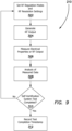
- FIG. 9 a flow diagram of an embodiment of process 210 for performing self-verification system test is shown.
- Self-verification process steps for various RF regulation modes and RF resolution settings are typically recorded or stored into a memory of the electrosurgical generator 10 of the present invention.
- each process step may have specific regulation values and impedance loads configuration.
- Exemplary self-verification processes were provided further above in Table I.
- the depicted portion of the process begins in blocks 302 where the algorithm sets the RF regulation modes and RF resolution settings. As such, the processing sets the voltage mode, activates appropriate relays 81 for obtaining specific load configuration and sets the regulation value.
- the processing then goes to block 304 for generating RF output and providing RF energy to the verification system loads.
- the RF amplifier 40 generates the RF output and supplies the RF output to internal loads 82 within the amplifier as directed by the self-verification system.
- the control system 100 in accordance with various embodiments of the present invention, regulates the RF output to the set value as directed by the self-verification system and the feedback system 60 measures voltage, current, power, and/or phase from the main, redundant and verification channels 601, 602, and 603.
- the feedback system 60 communicates the measured data and/or real and imaginary components thereof for the channels 601, 602, and 603 to the primary microcontroller 50 for further processing.
- the primary microcontroller 50 in various embodiments compares the data or readings of the main and redundant channels 601 and 602 to the verification channel 603 and if the main and redundant readings are less than a predefined tolerance or difference, e.g., 5%, the self-verification process step or test is passed or verified. Otherwise, the verification process step or test fails.
- a predefined tolerance or difference e.g., 5%
- the self-verification process step or test is passed or verified. Otherwise, the verification process step or test fails.
- the results are recorded or stored into a memory of the electrosurgical generator 10 and/or the device key 21 of the electrosurgical instrument 20.
- the self-verification system test activates at a predetermined condition, such as on power-on, device connection and/or script or device activation, and/or along a predetermined schedule, e.g., at each predetermined conditions and/or a selected interval.
- a separate button, switch or the like is provided on the generator, a connectable device and/or adapter utilized to activate the self-verification test.
- the electrosurgical generator 10, is configured to operate in one or more specific voltage modes.
- the voltage modes are low, medium and high and in various embodiments the voltage mode adjusts or effects the feedback system 60.
- Voltage mode determines gain settings on the ADCs (Digital to Analog Convertors) used in the feedback system 60 and in various embodiments, high voltage is a maximum 300V gain settings, medium voltage is a maximum 150V gain settings, and low voltage is a maximum 10V gain settings. By having different gain settings for the different voltage modes, the resolution of the measurement of the feedback system 60 is increased.
- the RF amplifier may include an autotransformer directly connected to a primary transformer of the RF amplifer to supply high voltage mode.
- the RF output may reach up to 300V and 4A.
- the RF amplifier 40 may operate in the normal voltage mode, RF output limited to 150V and 8A, and in the low voltage mode or passive mode which is limited to 10V and 100mA.
- the self-verification system test varies the voltage modes to test or ensure the different gain settings are accurate across the main, redundant and verification channels 601, 602, and 603 of the feedback system 60.
- different regulation modes of voltage, current and power are also included with the various voltage modes which are utilized and tested in the self-verification system test.
- the measurements and calculations provided by the main and redundant channel 601 and 602 are compared to the measurements and calculations of the verification channel 603. If the channels 601, 602, and 603 all match and in various embodiments within a set tolerance, then the self-verification system test according to the embodiments of the present invention clears or allows the electrosurgical generator 10 to continue and thus allow RF output to a connected electrosurgical device 20.
- the main, redundant and verification channels 601, 602, and 603 in various embodiments must also be within a set tolerance compared to a nominal regulation value to also allow the verification system to clear the generator for operation.
- the low voltage mode is only used for passive measurement and does not set a constant voltage, current, or power. In various embodiments, it also does not utilize the verification channel 603 and thus RF output is provided in low voltage. In this embodiment, voltage and current are measured, the resistance is calculated and some or all of the measurements and calculations are compared to predefined values and/or within a predefined tolerance to further clear or allow the electrosurgical generator 10 for further operations.
- the self-verification system determines or checks the drift of the sense devices such as, for example, resistors, capacitors or inductors of the main and redundant channels 601 and 602 which are used to measure or calculate electrical properties of the RF output. If the drift of these components is minimal or within a predefined range and/or the unit can regulate to set values appropriately, then the RF output of the electrosurgical generator 10 is determined to have no failure by the self-verification system test and the self-verification process allows the generator 10 for further operational or surgical use.
- the sense devices such as, for example, resistors, capacitors or inductors of the main and redundant channels 601 and 602 which are used to measure or calculate electrical properties of the RF output.
- FIG. 10 illustrates a flow diagram of an example method for performing a self-verification system test of an electrosurgical generator 10.
- This process or system test verifies that the electrosurgical generator 10 can output RF energy at a set value, and that the feedback system 60 is accurately measuring this RF output across all channels 601, 602 and 603.
- RF output is first generated and thus provided to the self-verification system.
- the generator when the generator is powered on, e.g., the power button 18 on the front panel of the generator 10 is pressed, the generator 10 initiates the self-verification system process. This will cause the RF output to be supplied or be directed to an internal load rather than through a connected electrosurgical device 20. As shown in FIG.
- the self-verification process bypasses or switches off relays 1 and 2 that would direct the RF output or the electrosurgical energy to a connected electrosurgical device, e.g., fusion device 20.
- a connected electrosurgical device e.g., fusion device 20.
- an electrosurgical device does not need to be connected to the electrosurgical generator 10 for the self-verification system to operate or to its processes to proceed. Accordingly, the processing switches toward the internal loads as directed by the self-verification system.
- relays 6-8 are switched on/off in various sequences to provide the associated internal load configuration as needed.
- relays 6 and 7 may be activated or used simultaneously and in parallel to assist in dissipating power and/or heat.
- relay 8 in various embodiments is switched on or used to include phase variations as desired.
- relays 4 and 5 of the exemplary embodiment are used to switch in a high voltage transformer.
- Relay 3 in various embodiments, is used or activated to provide the return path or complete the circuit for the self-verification system.
- the self-verification system may include a plurality of relays and loads including, for example, resistors, capacitors, inductors and various combinations thereof and as such other relays, loads and combinations thereof are not shown for ease of readability.
- the self-verification system may include a timer to ensure that the self-verification system test is not activated or initiated needlessly or is activated as intended. As such, if the electrosurgical generator 10 is quickly powered on and off, e.g., in less than a second, the self-verification system does not activate and in various embodiments prevents potential thermal damage to the load such as, for example, resistors.
- the timer is configured to start at or near power-on time and reaches or passes a predefined threshold to cause or initiate activation of the self-verification system.
Landscapes
- Health & Medical Sciences (AREA)
- Surgery (AREA)
- Engineering & Computer Science (AREA)
- Life Sciences & Earth Sciences (AREA)
- Biomedical Technology (AREA)
- Otolaryngology (AREA)
- Nuclear Medicine, Radiotherapy & Molecular Imaging (AREA)
- Plasma & Fusion (AREA)
- Physics & Mathematics (AREA)
- Heart & Thoracic Surgery (AREA)
- Medical Informatics (AREA)
- Molecular Biology (AREA)
- Animal Behavior & Ethology (AREA)
- General Health & Medical Sciences (AREA)
- Public Health (AREA)
- Veterinary Medicine (AREA)
- Surgical Instruments (AREA)
Claims (15)
- Elektrochirurgisches System zur Durchführung chirurgischer Eingriffe, umfassend:
einen elektrochirurgischen Generator (10), der dazu eingerichtet ist, bei Aktivierung des Generators einen Selbstverifizierungssystemtest durchzuführen, wobei der Generator umfasst:einen Prozessor (50), der konfiguriert ist zum:Bewirken eines Initiierens des Selbstverifizierungssystemtests;Bewirken eines Zuführens von HF-Energie zu einer verbundenen elektrochirurgischen Handvorrichtung (20, 20'), wenn ein Ausfall des Generators nicht erfasst wird; undBewirken eines Erzeugens eines Systemfehlers, wenn der Ausfall des Generators erfasst wird und eine Ausfallschwelle erreicht ist; undeine Vielzahl von schaltbaren Impedanzlasten (81, 82), die zur Verwendung während des Selbstverifizierungssystemtests konfiguriert ist,dadurch gekennzeichnet, dassder Prozessor weiterhin dazu konfiguriert ist, das Initiieren des Selbstverifizierungssystemtests nach Bestimmen, dass ein vorbestimmter Zeitraum nach dem Starten des Generators verstrichen ist, zu bewirken; undwobei der Selbstverifizierungssystemtest einen Verifizierungsalgorithmus umfasst, der verifiziert, dass die zugeführte HF-Energie zu der Vielzahl von schaltbaren Impedanzlasten über eine Vielzahl von HF-Auflösungseinstellungen und eine Vielzahl von HF-Regelungsmodi geleitet wird, wobei die Vielzahl von schaltbaren Impedanzlasten (81, 82) für jede der Vielzahlen von HF-Auflösungseinstellungen und HF-Regelungsmodi auf eine spezifische Lastkonfiguration eingestellt ist. - Elektrochirurgisches System nach Anspruch 1, wobei der Prozessor (50) weiterhin dazu konfiguriert ist, ein Neustarten des Generators zu bewirken, um den Selbstverifizierungssystemtest erneut zu initiieren, wenn der Ausfall des Generators erfasst wird und die Ausfallschwelle nicht erreicht ist.
- Elektrochirurgisches System nach Anspruch 1, wobei die Ausfallschwelle eine Anzahl von aufeinanderfolgenden Malen umfasst, wobei der Selbstverifizierungssystemtest den Ausfall des Generators erfasst.
- Elektrochirurgisches System nach Anspruch 1, wobei der Prozessor (50) dazu konfiguriert ist, bei Aktivierung des Generators zu bestimmen, ob ein Fehlschlag des vorherigen Selbstverifizierungssystemtests aufgetreten ist.
- Elektrochirurgisches System nach Anspruch 4, wobei, wenn der Fehlschlag des vorherigen Selbstverifizierungssystemtests erfasst wird, der Prozessor (50) bewirkt, dass der Generator für eine Abkühlphase wartet.
- Elektrochirurgisches System nach Anspruch 4, wobei, wenn der Fehlschlag des vorherigen Selbstverifizierungssystemtests nicht erfasst wird, der Prozessor (50) weiterhin bestimmt, ob eine Einschaltschwellenzeit nach dem Starten des Generators und vor dem Initiieren des Selbstverifizierungssystemtests verstrichen ist.
- Elektrochirurgisches System nach Anspruch 1, wobei die Vielzahl von HF-Auflösungseinstellungen eine von einer Niederspannungseinstellung, einer Mittelspannungseinstellung oder einer Hochspannungseinstellung umfasst; wobei die Niederspannungseinstellung eine Ausgangs-HF-Energie von bis zu 10 V oder 100 mA aufweist, die Mittelspannungseinstellung eine Ausgangs-HF-Energie von bis zu 150 V oder 8 A aufweist und die Hochspannungseinstellung eine Ausgangs-HF-Energie von bis zu 300 V oder 4 A aufweist.
- Elektrochirurgisches System nach Anspruch 7, wobei eine Vielzahl von HF-Regelungssollwerten und eine Vielzahl von spezifischen Lastkonfigurationen für jede HF-Auflösungseinstellung vorliegen und wobei die Vielzahl von HF-Regelungsmodi für jede der Vielzahlen von HF-Regelungseinstellungen und spezifischen Lastkonfigurationen einen von einem Spannungsregelungsmodus, einem Stromregelungsmodus oder einem Leistungsregelungsmodus umfasst.
- Elektrochirurgisches System nach Anspruch 1, wobei der Prozessor (50) weiterhin dazu konfiguriert ist, eine Aktivierung der spezifischen Lastkonfiguration der Vielzahl von schaltbaren Impedanzlasten zu bewirken und den HF-Ausgang des Generators auf einen vorbestimmten Sollwert für jede der Vielzahlen von HF-Regelungsmodi und HF-Auflösungseinstellungen zu regeln.
- Elektrochirurgisches System nach Anspruch 1, wobei der Generator (10) weiterhin ein Rückmeldesystem (60) umfasst, das zum Messen elektrischer Eigenschaften eines HF-Ausgangs über eine Vielzahl von Kanälen konfiguriert ist.
- Elektrochirurgisches System nach Anspruch 10, wobei der Prozessor das Zuführen von HF-Energie zu der verbundenen elektrochirurgischen Handvorrichtung (20, 20') zulässt, wenn alle Messwerte der Vielzahl von Kanälen miteinander übereinstimmen und/oder innerhalb einer bestimmten Toleranz über die Vielzahlen von HF-Regelungsmodi und HF-Auflösungseinstellungen liegen.
- Elektrochirurgisches System nach Anspruch 10 oder 11, wobei das Rückmeldesystem (60) einen Analogeingang, eine digitale Verarbeitung und einen Digitalausgang umfasst.
- Elektrochirurgisches System nach Anspruch 1, wobei die Vielzahl von schaltbaren Impedanzlasten (81, 82) internal zu dem oder in den Generator integriert sind und nur dazu verwendet werden, den Selbstverifizierungssystemtest bei Aktivierung des Generators durchzuführen.
- Elektrochirurgisches System nach Anspruch 1, wobei die Vielzahl von schaltbaren Impedanzlasten mindestens ein oder mehrere Relais (81) umfasst, um eine selektive Verbindung zwischen einer Vielzahl von Widerständen, Kondensatoren oder Induktoren zu vermitteln; wobei der Prozessor (50) in dem mindestens einen oder den mehreren Relais (81) schaltet, um die spezifische Lastkonfiguration für jede der Vielzahlen von HF-Auflösungseinstellungen und HF-Regelungsmodi zu aktivieren.
- Elektrochirurgisches System nach Anspruch 1, wobei der Ausfall des Generators erfasst wird, wenn ein oder mehrere oder alle Selbstverifizierungsprozessschritte über die Vielzahlen von HF-Auflösungseinstellungen und HF-Regelungsmodi fehlschlagen.
Priority Applications (1)
| Application Number | Priority Date | Filing Date | Title |
|---|---|---|---|
| EP24207068.8A EP4470492A3 (de) | 2018-09-05 | 2019-09-05 | System zur verifikation elektrochirurgischer generatoren |
Applications Claiming Priority (2)
| Application Number | Priority Date | Filing Date | Title |
|---|---|---|---|
| US201862727176P | 2018-09-05 | 2018-09-05 | |
| PCT/US2019/049768 WO2020051343A1 (en) | 2018-09-05 | 2019-09-05 | Electrosurgical generator verification system |
Related Child Applications (2)
| Application Number | Title | Priority Date | Filing Date |
|---|---|---|---|
| EP24207068.8A Division EP4470492A3 (de) | 2018-09-05 | 2019-09-05 | System zur verifikation elektrochirurgischer generatoren |
| EP24207068.8A Division-Into EP4470492A3 (de) | 2018-09-05 | 2019-09-05 | System zur verifikation elektrochirurgischer generatoren |
Publications (2)
| Publication Number | Publication Date |
|---|---|
| EP3846709A1 EP3846709A1 (de) | 2021-07-14 |
| EP3846709B1 true EP3846709B1 (de) | 2024-12-18 |
Family
ID=67998740
Family Applications (2)
| Application Number | Title | Priority Date | Filing Date |
|---|---|---|---|
| EP19772930.4A Active EP3846709B1 (de) | 2018-09-05 | 2019-09-05 | Prüfsystem für elektrochirurgischen generator |
| EP24207068.8A Pending EP4470492A3 (de) | 2018-09-05 | 2019-09-05 | System zur verifikation elektrochirurgischer generatoren |
Family Applications After (1)
| Application Number | Title | Priority Date | Filing Date |
|---|---|---|---|
| EP24207068.8A Pending EP4470492A3 (de) | 2018-09-05 | 2019-09-05 | System zur verifikation elektrochirurgischer generatoren |
Country Status (7)
| Country | Link |
|---|---|
| EP (2) | EP3846709B1 (de) |
| JP (3) | JP7372314B2 (de) |
| KR (1) | KR102956908B1 (de) |
| AU (2) | AU2019336199B2 (de) |
| CA (1) | CA3111782A1 (de) |
| ES (1) | ES3006612T3 (de) |
| WO (1) | WO2020051343A1 (de) |
Families Citing this family (1)
| Publication number | Priority date | Publication date | Assignee | Title |
|---|---|---|---|---|
| EP3846709B1 (de) * | 2018-09-05 | 2024-12-18 | Applied Medical Resources Corporation | Prüfsystem für elektrochirurgischen generator |
Family Cites Families (15)
| Publication number | Priority date | Publication date | Assignee | Title |
|---|---|---|---|---|
| JPS61141355A (ja) * | 1984-12-14 | 1986-06-28 | オリンパス光学工業株式会社 | 高周波焼灼装置 |
| EP0285962B1 (de) * | 1987-04-10 | 1993-02-17 | Siemens Aktiengesellschaft | Überwachungsschaltung für ein HF-Chirurgiegerät |
| US5484400A (en) * | 1992-08-12 | 1996-01-16 | Vidamed, Inc. | Dual channel RF delivery system |
| GB9911956D0 (en) * | 1999-05-21 | 1999-07-21 | Gyrus Medical Ltd | Electrosurgery system and method |
| WO2004083797A2 (en) * | 2003-03-14 | 2004-09-30 | Thermosurgery Technologies, Inc. | Hyperthermia treatment system |
| US8685016B2 (en) * | 2006-01-24 | 2014-04-01 | Covidien Ag | System and method for tissue sealing |
| US8845630B2 (en) * | 2007-06-15 | 2014-09-30 | Syneron Medical Ltd | Devices and methods for percutaneous energy delivery |
| US9375247B2 (en) * | 2011-03-16 | 2016-06-28 | Covidien Lp | System and method for electrosurgical generator power measurement |
| US9037447B2 (en) | 2012-01-27 | 2015-05-19 | Covidien Lp | Systems and methods for phase predictive impedance loss model calibration and compensation |
| US9192425B2 (en) * | 2012-06-26 | 2015-11-24 | Covidien Lp | System and method for testing electrosurgical generators |
| US9895186B2 (en) * | 2013-03-11 | 2018-02-20 | Covidien | Systems and methods for detecting abnormalities within a circuit of an electrosurgical generator |
| AU2015258819B2 (en) * | 2014-05-16 | 2019-12-12 | Applied Medical Resources Corporation | Electrosurgical system |
| US10085801B2 (en) * | 2014-08-25 | 2018-10-02 | Covidien Lp | Systems and methods for using a digital controller to adjust one or more operations of a microwave generator |
| EP3846709B1 (de) * | 2018-09-05 | 2024-12-18 | Applied Medical Resources Corporation | Prüfsystem für elektrochirurgischen generator |
| EP3846717B1 (de) * | 2018-09-05 | 2024-12-18 | Applied Medical Resources Corporation | Steuerungssystem für elektrochirurgischen generator |
-
2019
- 2019-09-05 EP EP19772930.4A patent/EP3846709B1/de active Active
- 2019-09-05 AU AU2019336199A patent/AU2019336199B2/en active Active
- 2019-09-05 ES ES19772930T patent/ES3006612T3/es active Active
- 2019-09-05 KR KR1020217009830A patent/KR102956908B1/ko active Active
- 2019-09-05 EP EP24207068.8A patent/EP4470492A3/de active Pending
- 2019-09-05 WO PCT/US2019/049768 patent/WO2020051343A1/en not_active Ceased
- 2019-09-05 CA CA3111782A patent/CA3111782A1/en active Pending
- 2019-09-05 JP JP2021512215A patent/JP7372314B2/ja active Active
-
2023
- 2023-10-19 JP JP2023180149A patent/JP7591633B2/ja active Active
-
2024
- 2024-11-18 JP JP2024200584A patent/JP2025032134A/ja active Pending
-
2025
- 2025-07-22 AU AU2025206417A patent/AU2025206417A1/en active Pending
Also Published As
| Publication number | Publication date |
|---|---|
| EP4470492A2 (de) | 2024-12-04 |
| EP4470492A3 (de) | 2025-02-26 |
| WO2020051343A1 (en) | 2020-03-12 |
| JP2024010028A (ja) | 2024-01-23 |
| JP7372314B2 (ja) | 2023-10-31 |
| JP7591633B2 (ja) | 2024-11-28 |
| ES3006612T3 (en) | 2025-03-18 |
| AU2019336199B2 (en) | 2025-04-24 |
| JP2022500104A (ja) | 2022-01-04 |
| CA3111782A1 (en) | 2020-03-12 |
| EP3846709A1 (de) | 2021-07-14 |
| AU2019336199A1 (en) | 2021-03-25 |
| AU2025206417A1 (en) | 2025-08-07 |
| JP2025032134A (ja) | 2025-03-11 |
| KR20210057753A (ko) | 2021-05-21 |
| KR102956908B1 (ko) | 2026-04-24 |
Similar Documents
| Publication | Publication Date | Title |
|---|---|---|
| US20230346454A1 (en) | Electrosurgical system | |
| US12551262B2 (en) | Electrosurgical generator control system | |
| US8653994B2 (en) | System and method for detection of ADC errors | |
| EP3991678B1 (de) | Elektrochirurgische instrumente und verbindungen dafür | |
| JP7591633B2 (ja) | 電気手術発生器検証システム | |
| US20200069357A1 (en) | Electrosurgical generator verification system | |
| KR20260069747A (ko) | 전기수술용 발전기 검증 시스템 |
Legal Events
| Date | Code | Title | Description |
|---|---|---|---|
| STAA | Information on the status of an ep patent application or granted ep patent |
Free format text: STATUS: UNKNOWN |
|
| STAA | Information on the status of an ep patent application or granted ep patent |
Free format text: STATUS: THE INTERNATIONAL PUBLICATION HAS BEEN MADE |
|
| PUAI | Public reference made under article 153(3) epc to a published international application that has entered the european phase |
Free format text: ORIGINAL CODE: 0009012 |
|
| STAA | Information on the status of an ep patent application or granted ep patent |
Free format text: STATUS: REQUEST FOR EXAMINATION WAS MADE |
|
| 17P | Request for examination filed |
Effective date: 20210208 |
|
| AK | Designated contracting states |
Kind code of ref document: A1 Designated state(s): AL AT BE BG CH CY CZ DE DK EE ES FI FR GB GR HR HU IE IS IT LI LT LU LV MC MK MT NL NO PL PT RO RS SE SI SK SM TR |
|
| DAV | Request for validation of the european patent (deleted) | ||
| DAX | Request for extension of the european patent (deleted) | ||
| STAA | Information on the status of an ep patent application or granted ep patent |
Free format text: STATUS: EXAMINATION IS IN PROGRESS |
|
| 17Q | First examination report despatched |
Effective date: 20230605 |
|
| GRAP | Despatch of communication of intention to grant a patent |
Free format text: ORIGINAL CODE: EPIDOSNIGR1 |
|
| STAA | Information on the status of an ep patent application or granted ep patent |
Free format text: STATUS: GRANT OF PATENT IS INTENDED |
|
| INTG | Intention to grant announced |
Effective date: 20240710 |
|
| GRAS | Grant fee paid |
Free format text: ORIGINAL CODE: EPIDOSNIGR3 |
|
| GRAA | (expected) grant |
Free format text: ORIGINAL CODE: 0009210 |
|
| STAA | Information on the status of an ep patent application or granted ep patent |
Free format text: STATUS: THE PATENT HAS BEEN GRANTED |
|
| P01 | Opt-out of the competence of the unified patent court (upc) registered |
Free format text: CASE NUMBER: APP_56417/2024 Effective date: 20241016 |
|
| RIN1 | Information on inventor provided before grant (corrected) |
Inventor name: GORIN, IGOR Inventor name: SOTO, ANDREW Inventor name: ADL, SEAN |
|
| AK | Designated contracting states |
Kind code of ref document: B1 Designated state(s): AL AT BE BG CH CY CZ DE DK EE ES FI FR GB GR HR HU IE IS IT LI LT LU LV MC MK MT NL NO PL PT RO RS SE SI SK SM TR |
|
| REG | Reference to a national code |
Ref country code: CH Ref legal event code: EP |
|
| REG | Reference to a national code |
Ref country code: DE Ref legal event code: R096 Ref document number: 602019063700 Country of ref document: DE |
|
| REG | Reference to a national code |
Ref country code: IE Ref legal event code: FG4D |
|
| REG | Reference to a national code |
Ref country code: NL Ref legal event code: FP |
|
| REG | Reference to a national code |
Ref country code: ES Ref legal event code: FG2A Ref document number: 3006612 Country of ref document: ES Kind code of ref document: T3 Effective date: 20250318 |
|
| REG | Reference to a national code |
Ref country code: LT Ref legal event code: MG9D |
|
| PG25 | Lapsed in a contracting state [announced via postgrant information from national office to epo] |
Ref country code: HR Free format text: LAPSE BECAUSE OF FAILURE TO SUBMIT A TRANSLATION OF THE DESCRIPTION OR TO PAY THE FEE WITHIN THE PRESCRIBED TIME-LIMIT Effective date: 20241218 |
|
| PG25 | Lapsed in a contracting state [announced via postgrant information from national office to epo] |
Ref country code: FI Free format text: LAPSE BECAUSE OF FAILURE TO SUBMIT A TRANSLATION OF THE DESCRIPTION OR TO PAY THE FEE WITHIN THE PRESCRIBED TIME-LIMIT Effective date: 20241218 |
|
| PG25 | Lapsed in a contracting state [announced via postgrant information from national office to epo] |
Ref country code: BG Free format text: LAPSE BECAUSE OF FAILURE TO SUBMIT A TRANSLATION OF THE DESCRIPTION OR TO PAY THE FEE WITHIN THE PRESCRIBED TIME-LIMIT Effective date: 20241218 |
|
| PG25 | Lapsed in a contracting state [announced via postgrant information from national office to epo] |
Ref country code: NO Free format text: LAPSE BECAUSE OF FAILURE TO SUBMIT A TRANSLATION OF THE DESCRIPTION OR TO PAY THE FEE WITHIN THE PRESCRIBED TIME-LIMIT Effective date: 20250318 |
|
| PG25 | Lapsed in a contracting state [announced via postgrant information from national office to epo] |
Ref country code: LV Free format text: LAPSE BECAUSE OF FAILURE TO SUBMIT A TRANSLATION OF THE DESCRIPTION OR TO PAY THE FEE WITHIN THE PRESCRIBED TIME-LIMIT Effective date: 20241218 Ref country code: GR Free format text: LAPSE BECAUSE OF FAILURE TO SUBMIT A TRANSLATION OF THE DESCRIPTION OR TO PAY THE FEE WITHIN THE PRESCRIBED TIME-LIMIT Effective date: 20250319 |
|
| PG25 | Lapsed in a contracting state [announced via postgrant information from national office to epo] |
Ref country code: RS Free format text: LAPSE BECAUSE OF FAILURE TO SUBMIT A TRANSLATION OF THE DESCRIPTION OR TO PAY THE FEE WITHIN THE PRESCRIBED TIME-LIMIT Effective date: 20250318 |
|
| REG | Reference to a national code |
Ref country code: AT Ref legal event code: MK05 Ref document number: 1751585 Country of ref document: AT Kind code of ref document: T Effective date: 20241218 |
|
| PG25 | Lapsed in a contracting state [announced via postgrant information from national office to epo] |
Ref country code: SM Free format text: LAPSE BECAUSE OF FAILURE TO SUBMIT A TRANSLATION OF THE DESCRIPTION OR TO PAY THE FEE WITHIN THE PRESCRIBED TIME-LIMIT Effective date: 20241218 |
|
| PG25 | Lapsed in a contracting state [announced via postgrant information from national office to epo] |
Ref country code: PL Free format text: LAPSE BECAUSE OF FAILURE TO SUBMIT A TRANSLATION OF THE DESCRIPTION OR TO PAY THE FEE WITHIN THE PRESCRIBED TIME-LIMIT Effective date: 20241218 |
|
| PG25 | Lapsed in a contracting state [announced via postgrant information from national office to epo] |
Ref country code: IS Free format text: LAPSE BECAUSE OF FAILURE TO SUBMIT A TRANSLATION OF THE DESCRIPTION OR TO PAY THE FEE WITHIN THE PRESCRIBED TIME-LIMIT Effective date: 20250418 |
|
| PG25 | Lapsed in a contracting state [announced via postgrant information from national office to epo] |
Ref country code: PT Free format text: LAPSE BECAUSE OF FAILURE TO SUBMIT A TRANSLATION OF THE DESCRIPTION OR TO PAY THE FEE WITHIN THE PRESCRIBED TIME-LIMIT Effective date: 20250421 |
|
| PG25 | Lapsed in a contracting state [announced via postgrant information from national office to epo] |
Ref country code: EE Free format text: LAPSE BECAUSE OF FAILURE TO SUBMIT A TRANSLATION OF THE DESCRIPTION OR TO PAY THE FEE WITHIN THE PRESCRIBED TIME-LIMIT Effective date: 20241218 |
|
| PG25 | Lapsed in a contracting state [announced via postgrant information from national office to epo] |
Ref country code: RO Free format text: LAPSE BECAUSE OF FAILURE TO SUBMIT A TRANSLATION OF THE DESCRIPTION OR TO PAY THE FEE WITHIN THE PRESCRIBED TIME-LIMIT Effective date: 20241218 Ref country code: AT Free format text: LAPSE BECAUSE OF FAILURE TO SUBMIT A TRANSLATION OF THE DESCRIPTION OR TO PAY THE FEE WITHIN THE PRESCRIBED TIME-LIMIT Effective date: 20241218 |
|
| PG25 | Lapsed in a contracting state [announced via postgrant information from national office to epo] |
Ref country code: SK Free format text: LAPSE BECAUSE OF FAILURE TO SUBMIT A TRANSLATION OF THE DESCRIPTION OR TO PAY THE FEE WITHIN THE PRESCRIBED TIME-LIMIT Effective date: 20241218 |
|
| PG25 | Lapsed in a contracting state [announced via postgrant information from national office to epo] |
Ref country code: CZ Free format text: LAPSE BECAUSE OF FAILURE TO SUBMIT A TRANSLATION OF THE DESCRIPTION OR TO PAY THE FEE WITHIN THE PRESCRIBED TIME-LIMIT Effective date: 20241218 |
|
| PG25 | Lapsed in a contracting state [announced via postgrant information from national office to epo] |
Ref country code: SE Free format text: LAPSE BECAUSE OF FAILURE TO SUBMIT A TRANSLATION OF THE DESCRIPTION OR TO PAY THE FEE WITHIN THE PRESCRIBED TIME-LIMIT Effective date: 20241218 |
|
| REG | Reference to a national code |
Ref country code: DE Ref legal event code: R097 Ref document number: 602019063700 Country of ref document: DE |
|
| PG25 | Lapsed in a contracting state [announced via postgrant information from national office to epo] |
Ref country code: DK Free format text: LAPSE BECAUSE OF FAILURE TO SUBMIT A TRANSLATION OF THE DESCRIPTION OR TO PAY THE FEE WITHIN THE PRESCRIBED TIME-LIMIT Effective date: 20241218 |
|
| PGFP | Annual fee paid to national office [announced via postgrant information from national office to epo] |
Ref country code: DE Payment date: 20250929 Year of fee payment: 7 |
|
| PGFP | Annual fee paid to national office [announced via postgrant information from national office to epo] |
Ref country code: NL Payment date: 20250926 Year of fee payment: 7 Ref country code: IT Payment date: 20250919 Year of fee payment: 7 |
|
| PGFP | Annual fee paid to national office [announced via postgrant information from national office to epo] |
Ref country code: GB Payment date: 20250929 Year of fee payment: 7 |
|
| PGFP | Annual fee paid to national office [announced via postgrant information from national office to epo] |
Ref country code: FR Payment date: 20250925 Year of fee payment: 7 |
|
| PGFP | Annual fee paid to national office [announced via postgrant information from national office to epo] |
Ref country code: IE Payment date: 20250929 Year of fee payment: 7 |
|
| PLBE | No opposition filed within time limit |
Free format text: ORIGINAL CODE: 0009261 |
|
| STAA | Information on the status of an ep patent application or granted ep patent |
Free format text: STATUS: NO OPPOSITION FILED WITHIN TIME LIMIT |
|
| REG | Reference to a national code |
Ref country code: CH Ref legal event code: L10 Free format text: ST27 STATUS EVENT CODE: U-0-0-L10-L00 (AS PROVIDED BY THE NATIONAL OFFICE) Effective date: 20251029 |
|
| 26N | No opposition filed |
Effective date: 20250919 |
|
| PGFP | Annual fee paid to national office [announced via postgrant information from national office to epo] |
Ref country code: ES Payment date: 20251001 Year of fee payment: 7 |
|
| REG | Reference to a national code |
Ref country code: CH Ref legal event code: H13 Free format text: ST27 STATUS EVENT CODE: U-0-0-H10-H13 (AS PROVIDED BY THE NATIONAL OFFICE) Effective date: 20260504 |