EP3846376A1 - Specific jump patterns for repeated transmission and reception of data - Google Patents
Specific jump patterns for repeated transmission and reception of data Download PDFInfo
- Publication number
- EP3846376A1 EP3846376A1 EP21158768.8A EP21158768A EP3846376A1 EP 3846376 A1 EP3846376 A1 EP 3846376A1 EP 21158768 A EP21158768 A EP 21158768A EP 3846376 A1 EP3846376 A1 EP 3846376A1
- Authority
- EP
- European Patent Office
- Prior art keywords
- pattern
- jump
- time
- data
- hop
- Prior art date
- Legal status (The legal status is an assumption and is not a legal conclusion. Google has not performed a legal analysis and makes no representation as to the accuracy of the status listed.)
- Granted
Links
- 230000005540 biological transmission Effects 0.000 title claims abstract description 154
- 238000000034 method Methods 0.000 claims description 87
- 235000008694 Humulus lupulus Nutrition 0.000 claims description 20
- 238000004590 computer program Methods 0.000 claims description 13
- 239000000969 carrier Substances 0.000 claims description 8
- 238000005311 autocorrelation function Methods 0.000 description 25
- 238000005314 correlation function Methods 0.000 description 23
- 238000010586 diagram Methods 0.000 description 20
- 238000013461 design Methods 0.000 description 16
- 239000011159 matrix material Substances 0.000 description 15
- 238000004364 calculation method Methods 0.000 description 7
- 238000004891 communication Methods 0.000 description 7
- 230000003252 repetitive effect Effects 0.000 description 6
- 230000008569 process Effects 0.000 description 5
- 238000003860 storage Methods 0.000 description 5
- 230000002123 temporal effect Effects 0.000 description 5
- 238000001514 detection method Methods 0.000 description 4
- 238000013507 mapping Methods 0.000 description 4
- 230000006399 behavior Effects 0.000 description 3
- 238000012938 design process Methods 0.000 description 3
- 230000002349 favourable effect Effects 0.000 description 3
- 230000006870 function Effects 0.000 description 3
- 238000005457 optimization Methods 0.000 description 3
- 238000000342 Monte Carlo simulation Methods 0.000 description 2
- 238000013459 approach Methods 0.000 description 2
- 230000001174 ascending effect Effects 0.000 description 2
- 230000008901 benefit Effects 0.000 description 2
- 230000008859 change Effects 0.000 description 2
- 230000036039 immunity Effects 0.000 description 2
- 239000010453 quartz Substances 0.000 description 2
- VYPSYNLAJGMNEJ-UHFFFAOYSA-N silicon dioxide Inorganic materials O=[Si]=O VYPSYNLAJGMNEJ-UHFFFAOYSA-N 0.000 description 2
- 238000001228 spectrum Methods 0.000 description 2
- 238000012360 testing method Methods 0.000 description 2
- 230000002457 bidirectional effect Effects 0.000 description 1
- 230000015572 biosynthetic process Effects 0.000 description 1
- 238000012937 correction Methods 0.000 description 1
- 239000013078 crystal Substances 0.000 description 1
- 230000007423 decrease Effects 0.000 description 1
- 230000001419 dependent effect Effects 0.000 description 1
- 238000011161 development Methods 0.000 description 1
- 230000018109 developmental process Effects 0.000 description 1
- 230000000694 effects Effects 0.000 description 1
- 238000005516 engineering process Methods 0.000 description 1
- 238000003306 harvesting Methods 0.000 description 1
- 238000010438 heat treatment Methods 0.000 description 1
- 238000012986 modification Methods 0.000 description 1
- 230000004048 modification Effects 0.000 description 1
- 230000003287 optical effect Effects 0.000 description 1
- 238000012545 processing Methods 0.000 description 1
- 238000011084 recovery Methods 0.000 description 1
- 238000005070 sampling Methods 0.000 description 1
- 238000000926 separation method Methods 0.000 description 1
- 230000002459 sustained effect Effects 0.000 description 1
Images


Classifications
-
- H—ELECTRICITY
- H04—ELECTRIC COMMUNICATION TECHNIQUE
- H04L—TRANSMISSION OF DIGITAL INFORMATION, e.g. TELEGRAPHIC COMMUNICATION
- H04L5/00—Arrangements affording multiple use of the transmission path
- H04L5/0001—Arrangements for dividing the transmission path
- H04L5/0003—Two-dimensional division
- H04L5/0005—Time-frequency
- H04L5/0007—Time-frequency the frequencies being orthogonal, e.g. OFDM(A), DMT
- H04L5/0012—Hopping in multicarrier systems
-
- H—ELECTRICITY
- H04—ELECTRIC COMMUNICATION TECHNIQUE
- H04B—TRANSMISSION
- H04B1/00—Details of transmission systems, not covered by a single one of groups H04B3/00 - H04B13/00; Details of transmission systems not characterised by the medium used for transmission
- H04B1/69—Spread spectrum techniques
- H04B1/713—Spread spectrum techniques using frequency hopping
- H04B1/7136—Arrangements for generation of hop frequencies, e.g. using a bank of frequency sources, using continuous tuning or using a transform
-
- H—ELECTRICITY
- H04—ELECTRIC COMMUNICATION TECHNIQUE
- H04B—TRANSMISSION
- H04B1/00—Details of transmission systems, not covered by a single one of groups H04B3/00 - H04B13/00; Details of transmission systems not characterised by the medium used for transmission
- H04B1/69—Spread spectrum techniques
- H04B1/713—Spread spectrum techniques using frequency hopping
- H04B1/7143—Arrangements for generation of hop patterns
-
- H—ELECTRICITY
- H04—ELECTRIC COMMUNICATION TECHNIQUE
- H04B—TRANSMISSION
- H04B1/00—Details of transmission systems, not covered by a single one of groups H04B3/00 - H04B13/00; Details of transmission systems not characterised by the medium used for transmission
- H04B1/69—Spread spectrum techniques
- H04B1/713—Spread spectrum techniques using frequency hopping
- H04B1/715—Interference-related aspects
-
- H—ELECTRICITY
- H04—ELECTRIC COMMUNICATION TECHNIQUE
- H04B—TRANSMISSION
- H04B1/00—Details of transmission systems, not covered by a single one of groups H04B3/00 - H04B13/00; Details of transmission systems not characterised by the medium used for transmission
- H04B1/69—Spread spectrum techniques
- H04B1/713—Spread spectrum techniques using frequency hopping
- H04B1/7156—Arrangements for sequence synchronisation
-
- H—ELECTRICITY
- H04—ELECTRIC COMMUNICATION TECHNIQUE
- H04L—TRANSMISSION OF DIGITAL INFORMATION, e.g. TELEGRAPHIC COMMUNICATION
- H04L5/00—Arrangements affording multiple use of the transmission path
- H04L5/003—Arrangements for allocating sub-channels of the transmission path
- H04L5/0044—Arrangements for allocating sub-channels of the transmission path allocation of payload
Definitions
- Exemplary embodiments relate to a data transmitter and a method for operating the same. Further exemplary embodiments relate to a data receiver and a method for operating the same. Further exemplary embodiments relate to the generation of specific jump patterns for repeated transmission of data. Further exemplary embodiments relate to repeated transmission and reception of data using specific jump patterns. Some exemplary embodiments relate to an optimization process for generating hopping patterns for use in interleaved repetitions.
- telegram splitting process (telegram splitting process) is known, according to which a telegram (or data packet) is divided into a plurality of sub-data packets, which are transmitted using a jump pattern in time and optionally in frequency.
- a data transmission arrangement which has an energy harvesting element as an energy source.
- the data transmission arrangement is designed to send data using the telegram splitting method, with a partial packet due to be sent being either sent, temporarily stored and sent later, or discarded, depending on an amount of electrical energy that can be provided by the energy supply device.
- the telegram splitting process uses certain time-frequency hopping patterns to transmit data over the radio channel. In order to be able to decode a data packet successfully, it is necessary that the jump pattern that was used for sending is known at the receiver. To ensure this, global time and frequency hopping patterns are defined for telegram splitting networks that are known to all participants.
- the transmission is less immune to interference if the same time and / or frequency hopping pattern is used for data transmission by several nodes. If two nodes start a transmission with the same jump pattern within a short time window (e.g. the duration of a sub-data packet), then all sub-data packets of the telegram overlap and in the worst case delete each other.
- a short time window e.g. the duration of a sub-data packet
- the US 2016/044729 A1 relates to the generation of transmission patterns for D2D communication, such as Voice OverIP (VoIP).
- VoIP Voice OverIP
- the codec With VoIP, the codec generates a VoIP data packet every 20ms, which is sent out a total of 5 times within the 20ms (first transmission + 4 repeat transmissions).
- the pamphlet US 2005/0176371 A1 refers to the transmission of data in a short range communication system.
- a time frequency code (TFC) is used in document D1 to transmit the data.
- TFC time frequency code
- individual OFDM symbols are transmitted in directly consecutive time slots in different frequency bands.
- the present invention is therefore based on the object of creating a concept which increases the transmission security when several nodes use a time and / or frequency hopping pattern for the data transmission.
- Embodiments provide a data transmitter which is designed to transmit data in a first mode repeatedly using a first jump pattern and a second jump pattern, the data transmitter being designed to transmit data in a second mode once using a third jump pattern, the jump pattern of the first mode and the second mode are different.
- the data receiver can be designed to recognize a repeated transmission of data using the first jump pattern and / or the second jump pattern, and to recognize a simple transmission of data using the third jump pattern.
- the data receiver can be designed to detect one of the two jump patterns (e.g. the first jump pattern) in a receive data stream in order to receive the data transmitted with the one jump pattern Jump pattern) in the received data stream using the already detected jump pattern (e.g. first jump pattern) in order to receive the data transmitted with the other jump pattern (e.g. second jump pattern).
- the data transmitted with the first jump pattern and the data transmitted with the second jump pattern are the same due to the repetition.
- the first jump pattern and the second jump pattern can be selected from a first set of jump patterns, while the third jump pattern can be selected from a second set of jump patterns.
- the first set of jump patterns and the second set of jump patterns can be different.
- the data transmitter or the data receiver can select the first jump pattern and the second jump pattern from the first class of jump patterns for the transmission of data in the first mode, while a further data transmitter for the transmission of data in the second mode can select a jump pattern from the second class can choose from jump patterns. Since the first class of jump patterns and the second class of jump patterns are different, it can be ensured that even with a simultaneous or at least temporally overlapping transmission of data through the Data transmitter and the other data transmitter, the probability of a collision can be kept as low as possible.
- the first jump pattern and the second jump pattern in order to establish a connection between the data transmitter and the data receiver, can be selected from a third set of jump patterns in the second mode as well.
- the third set of jump patterns can be a subset of the first set of jump patterns or the second set of jump patterns, or can differ from these.
- the first hop pattern and the second hop pattern can be shifted to one another in at least one of the frequency and the time, so that the first hop pattern and the second hop pattern are at least partially nested in one another.
- both the first jump pattern and the second jump pattern can have jumps that are distributed in time and / or frequency so that the jumps of a jump pattern are spaced from one another in time and / or frequency, the first jump pattern and the second jump pattern can be shifted relative to one another in terms of time and / or frequency such that at least some of the jumps of the second jump pattern are arranged between at least some of the jumps of the first jump pattern.
- the jumps of the first jump pattern and the jumps of the second jump pattern can be arranged alternately in time.
- the first jump pattern and the second jump pattern can be different.
- jumps in the first jump pattern and jumps in the second jump pattern can be distributed differently in terms of time and / or frequency.
- two consecutive jumps (e.g. first jump and second jump) of the first jump pattern can have a different time interval and / or frequency interval than two consecutive jumps (e.g. first jump and second jump) of the second jump pattern.
- the second hopping pattern can be a version of the first hopping pattern that is shifted in frequency and / or time.
- the first hopping pattern and the second hopping pattern can be the same and only shifted in time and / or frequency.
- jumps in the first jump pattern and jumps in the second jump pattern can have the same relative time interval and frequency interval.
- the data transmitter can be designed to transmit the first hopping pattern and the second hopping pattern in only partially overlapping or different frequency bands.
- the data transmitter can be designed to send the first hopping pattern or the second hopping pattern randomly in one of at least two different frequency bands, and to transmit the other hopping pattern in the other frequency band.
- the data transmitter can be designed to determine a time offset and / or a frequency offset between the first hopping pattern and the second hopping pattern as a function of an operating parameter of the data transmitter.
- the data receiver can either know the operating parameters of the data transmitter or the data receiver is designed to determine the operating parameters, e.g. to estimate them or to calculate them by means of a hypothesis test.
- the operating parameter of the data transmitter can be an intrinsic parameter of the data transmitter itself, such as addressing information, identification information, a quartz tolerance, a frequency offset or available transmission energy.
- the operating parameter of the data transmitter 100 can be a parameter assigned to the data transmitter 100, such as an assigned frequency offset, an assigned time offset, a radio cell, a geographical position, a system time or a priority of the data transmitter or of the data to be sent by the data transmitter.
- the operating parameter of the data transmitter 100 can be at least a part of user data or error protection data.
- the operating parameter of the data transmitter 100 can be a random frequency offset or a random time offset.
- the method includes a step of sending data in a first mode repeatedly using a first jump pattern and a second jump pattern.
- the method further comprises a step of sending data in a second mode once below Use of a third jump pattern, the jump patterns of the first mode and the second mode being different.
- the method includes a step of receiving data in a first mode repeatedly using a first hop pattern and a second hop pattern.
- the method further comprises a step of receiving data in a second mode once using a third jump pattern, the jump patterns of the first mode and the second mode being different.
- the method further comprises a step of selecting the jump pattern from the plurality of jump patterns for the first set of jump patterns, the autocorrelation functions of which have predetermined autocorrelation properties in order to obtain jump patterns with predetermined autocorrelation properties for the first set of jump patterns, and selecting the jump patterns from the plurality of Jump patterns for the second set of jump patterns, the autocorrelation functions of which have predetermined autocorrelation properties, in order to obtain jump patterns with predetermined autocorrelation properties for the second set of jump patterns.
- a time interval between the jumps in the jump patterns for the second set of jump patterns can be at least as great as a temporal length of one of the jumps in the jump patterns for the first set of jump patterns.
- the time intervals between the jumps in the jump patterns within a predetermined jump pattern length can be equidistant with a deviation of ⁇ 20%.
- the method can include a step of mapping the plurality of jump patterns for the first set of jump patterns into a two-dimensional time and frequency allocation matrix, with the calculation of the applied thereon Autocorrelation functions and the mapping of the plurality of jump patterns for the second set of jump patterns in each case a two-dimensional time and frequency allocation matrix with applied calculation of the autocorrelation functions.
- the step of mapping the plurality of hopping patterns for the first set of hopping patterns and / or mapping the plurality of hopping patterns for the second set of hopping patterns can take place in each case taking into account any influences from neighboring frequency positions (adjacent channel interference).
- the autocorrelation functions can be two-dimensional autocorrelation functions.
- those jump patterns when selecting the jump patterns for the first set of jump patterns, those jump patterns can meet the specified autocorrelation properties whose secondary autocorrelation function maxima do not exceed a specified maximum first amplitude threshold value, and when the jump patterns for the second set of jump patterns are selected, those jump patterns meet the specified autocorrelation properties whose autocorrelation function secondary maxima do not exceed a predetermined maximum second amplitude threshold value.
- the first amplitude threshold value can be equal to the second amplitude threshold value.
- the first amplitude threshold value can be equal to a number of jumps that form a repetitive and in time and / or frequency shifted sub-jump pattern of the respective jump patterns for the first set of jump patterns
- the second amplitude threshold value equal to a number of jumps which form a repetitive and in time and / or frequency shifted sub-jump pattern of the respective jump patterns for the second set of jump patterns.
- those jump patterns when selecting the jump pattern for the first set of jump patterns, can meet the specified autocorrelation properties, the partial sum of which is formed from a specified number of largest amplitude values of the respective autocorrelation function, is smaller than a specified first threshold value, and when selecting the jump pattern for the second set of jump patterns those jump patterns meet the specified autocorrelation properties whose Partial sum formed over a predetermined number of largest amplitude values of the respective autocorrelation function is smaller than a predetermined second threshold value.
- the first threshold value can be selected such that at least two jump patterns for the first set of jump patterns meet the specified autocorrelation properties
- the second threshold value is selected such that at least two jump patterns for the second set of jump patterns meet the specified autocorrelation properties, or wherein the first threshold value and / or the second threshold value can be selected as a function of respective boundary parameters.
- the method can furthermore have a step of calculating cross-correlation functions between the jump patterns with predetermined autocorrelation properties for the first set of jump patterns and of cross-correlation functions between the jump patterns with predetermined autocorrelation properties for the second set of jump patterns.
- the method can have a step of selecting the jump patterns from the jump patterns with predetermined autocorrelation properties for the first set of jump patterns, the cross-correlation functions of which have predetermined cross-correlation properties, in order to obtain jump patterns with predetermined autocorrelation properties and predetermined cross-correlation properties for the first set of jump patterns, and the jump pattern the jump patterns with predetermined autocorrelation properties for the second set of jump patterns, the cross-correlation functions of which have predetermined cross-correlation properties in order to obtain jump patterns with predetermined autocorrelation properties and predetermined cross-correlation properties for the second set of jump patterns.
- cross-correlation functions between the jump patterns for the first set of jump patterns and the second jump patterns can be calculated, with only those jump patterns for the first set of jump patterns and / or the second set of jump patterns being selected when selecting the jump patterns whose cross-correlation functions between the jump patterns for the first set of jump patterns and the second set of jump patterns also have predetermined cross-correlation properties.
- the cross-correlation functions can be two-dimensional cross-correlation functions.
- those jump patterns when selecting the jump patterns from the jump patterns with predetermined autocorrelation properties for the first set of jump patterns, those jump patterns can meet the predetermined cross-correlation properties, the partial sums of which are formed from a predetermined number of largest amplitude values of the respective cross-correlation function and are smallest, and when the jump patterns are selected from the jump patterns with predetermined autocorrelation properties for the second set of jump patterns those jump patterns meet the predetermined cross-correlation properties, the partial sums of which are the smallest, formed over a predetermined number of largest amplitude values of the respective cross-correlation function.
- the jump patterns in the random generation of the plurality of jump patterns for the first set of jump patterns and the second set of jump patterns, can be generated such that the jumps of the respective jump patterns lie within a predetermined frequency band.
- the hopping pattern can be a combination of the time hopping pattern and the frequency hopping pattern, the time hopping pattern and the frequency hopping pattern in the respective table having the same line number.
- a data packet can be sent divided into a plurality of sub-data packets in accordance with the jump pattern, so that one sub-data packet of the plurality of sub-data packets is sent in each jump of the jump pattern.
- the hopping pattern can be a combination of the time hopping pattern and the frequency hopping pattern, the time hopping pattern and the frequency hopping pattern in the respective table having the same line number.
- a data packet can be received divided into a plurality of sub-data packets in accordance with the jump pattern, so that one sub-data packet of the plurality of sub-data packets is received in each jump of the jump pattern.
- Fig. 1 shows a schematic block diagram of a system with a data transmitter 100 and a data receiver 110, according to an embodiment of the present invention.
- the data transmitter 100 is designed to transmit data 120 using a jump pattern.
- the data receiver 110 is designed to receive data 120 from the data transmitter 100 using a jump pattern.
- the hop pattern 140 may have a plurality of hops 142 which are distributed in time and / or frequency.
- the data transmitter 100 can be designed to transmit data 120 in accordance with the hopping pattern 140, distributed in time and / or frequency.
- the data receiver 110 can be designed to receive data 120 received, which are sent distributed according to the hopping pattern 140 in the time and / or frequency.
- the data transmitter 100 can have a transmission device (or transmission module, or transmitter) 102 which is designed to transmit the data 120.
- the transmission device 102 can be connected to an antenna 104 of the data transmitter 100.
- the data transmitter 100 can furthermore have a receiving device (or receiving module, or receiver) 106 which is designed to receive data.
- the receiving device 106 can be connected to the antenna 104 or a further (separate) antenna of the data transmitter 100.
- the data transmitter 100 can also have a combined transceiver.
- the data receiver 110 can have a receiving device (or receiving module, or receiver) 116, which is designed to receive data 120.
- the receiving device 116 can be connected to an antenna 114 of the data receiver 110.
- the data receiver 110 can have a transmission device (or transmission module, or transmitter) 112 which is designed to transmit data.
- the transmitting device 112 can be connected to the antenna 114 or a further (separate) antenna of the data receiver 110.
- the data receiver 110 can also have a combined transceiver.
- the data transmitter 100 can be a sensor node, while the data receiver 110 can be a base station.
- a communication system comprises at least one data receiver 110 (base station) and a plurality of data transmitters (sensor nodes, such as heating meters).
- the data transmitter 100 is a base station
- the data receiver 110 is a sensor node.
- both the data transmitter 100 and the data receiver 110 to be sensor nodes.
- both the data transmitter 100 and the data receiver 110 to be base stations.
- the data transmitter 100 and the data receiver 110 can optionally be designed to send or receive data 120 using the telegram splitting method.
- a telegram or data packet 120 is divided into a plurality of sub-data packets (or partial data packets, or partial packets) 142 and the sub-data packets 142 are distributed over time and / or frequency distributed by data transmitter 100 in accordance with jump pattern 140 transmitted to the data receiver 110, the data receiver 110 returning the sub-data packets merges (or combines) to obtain the data packet 120.
- Each of the sub-data packets 142 contains only part of the data packet 120.
- the data packet 120 can also be channel-coded, so that not all sub-data packets 142 but only a portion of the sub-data packets 142 are required for error-free decoding of the data packet 120.
- the time distribution of the plurality of sub-data packets 142 can, as already mentioned, take place in accordance with a time and / or frequency hopping pattern.
- a time jump pattern can specify a sequence of transmission times or transmission time intervals with which the sub-data packets are sent. For example, a first sub-data packet can be sent at a first transmission time (or in a first transmission time slot) and a second sub-data packet at a second transmission time (or in a second transmission time slot), the first transmission time and the second transmission time being different.
- the time jump pattern can define (or specify, or specify) the first transmission time and the second transmission time.
- the time jump pattern can indicate the first transmission time and a time interval between the first transmission time and the second transmission time.
- the time jump pattern can also only indicate the time interval between the first point in time and the second transmission point in time. There may be pauses in transmission between the sub-data packets in which no transmission takes place.
- the sub-data packets can also overlap (overlap) in time.
- a frequency hopping pattern can specify a sequence of transmission frequencies or transmission frequency hops with which the sub-data packets are sent. For example, a first sub-data packet can be sent with a first transmission frequency (or in a first frequency channel) and a second sub-data packet with a second transmission frequency (or in a second frequency channel), the first transmission frequency and the second transmission frequency being different.
- the frequency hopping pattern can define (or specify, or specify) the first transmission frequency and the second transmission frequency.
- the frequency hopping pattern can indicate the first transmission frequency and a frequency spacing (transmission frequency hopping) between the first transmission frequency and the second transmission frequency.
- the frequency hopping pattern can also only specify the frequency spacing (transmission frequency hopping) between the first transmission frequency and the second transmission frequency.
- the plurality of sub-data packets 142 can also be transmitted from the data transmitter 100 to the data receiver 110, both in terms of time and frequency become.
- the distribution of the plurality of sub-data packets in terms of time and frequency can take place in accordance with a time and frequency hopping pattern.
- a time and frequency hopping pattern can be the combination of a time hopping pattern and a frequency hopping pattern, i.e. a sequence of transmission times or transmission time intervals with which the sub-data packets are transmitted, transmission times (or transmission time intervals) being assigned transmission frequencies (or transmission frequency hops).
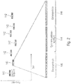
- Fig. 2 shows in a diagram an occupancy of the transmission channel during the transmission of a plurality of sub-data packets 142 according to a time and frequency hopping pattern.
- the ordinate describes the frequency and the abscissa describes the time.
- a synchronization sequence 144 can also be divided between the plurality of sub-data packets 142, so that the plurality of sub-data packets 142 in addition to data (data symbols in Fig. 2 ) 146 each part of the synchronization sequence (synchronization symbols in Fig. 2 ) 144 included.
- the data transmitter 100 shown can be expanded by a repeat transmission mode in which the data transmitter 100 transmits the data 120 using a first jump pattern and repeatedly (ie again) using a second jump pattern.
- the data transmitter 100 can be operated both in the repeated transmission mode and in a single transmission mode, ie as described above. Of course, the data transmitter 100 can also be operated in both modes.
- the data receiver 110 shown can be expanded by a repeat transmission mode in which the data receiver 110 receives the data 120 using a first jump pattern and repeatedly (ie again) using a second jump pattern.
- the data receiver 110 can be used both in the retransmission mode and in a single transmission mode, ie as described above, operated. Of course, the data receiver 110 can also be operated in both modes.
- the repetitive transmission mode is primarily discussed, with reference being made to the above description for the single transmission mode. It should also be noted that the above-described aspects of the single transmission mode are also applicable to the repetitive transmission mode.
- Fig. 3 shows a schematic block diagram of a system with a data transmitter 100 and a data receiver 110, according to an embodiment of the present invention.
- the data receiver 110 is designed to receive data 120 repeatedly in a first mode using a first jump pattern 140_1 and a second jump pattern 140_2. Furthermore, the data receiver 110 is designed to receive data 120 in a second mode simply (ie once or not repeatedly) using a third jump pattern 142 (cf. Fig. 1 ), where the jump patterns of the first mode and the second mode are different.
- the data receiver 110 can be designed to recognize a repeated transmission of data based on the first jump pattern 140_1 and / or the second jump pattern 140_2, and to recognize a simple transmission of data based on the third jump pattern.
- the data receiver can be designed to detect one of the two jump patterns (e.g. the first jump pattern) in a receive data stream in order to receive the data transmitted with the one jump pattern Jump pattern) in the received data stream using the already detected Determine jump pattern (e.g. first jump pattern) in order to receive the data transmitted with the other jump pattern (e.g. second jump pattern).
- one of the two jump patterns e.g. the first jump pattern
- the already detected Determine jump pattern e.g. first jump pattern
- the other jump pattern e.g. second jump pattern
- the detection can, for example, be designed in such a way that it detects almost all jump patterns (e.g. telegrams) up to a specified Es / N0 (e.g. approx. -3dB). Therefore, at lower Es / N0 it cannot be guaranteed that the detection will work for both transmissions. Due to the time and frequency coherence between the two transmissions (first jump pattern and second jump pattern) it is sufficient to detect only one of the two transmissions.
- the data receiver 110 can search for the jump patterns 140_1 and 140_2, in which case it should find at least one of the two jump patterns 140_1 and 140_2. The data receiver 110 can then decode this jump pattern and determine whether it is error-free. If it is not error-free, then the data receiver 110 can search for the other jump pattern, the data receiver 110 not knowing whether the previously found jump pattern was the first or second transmission (the first jump pattern 140_1 or second jump pattern 140_2). Since this was more difficult to find, individual decoding should not help here.
- MRC maximum ratio combining
- the first jump pattern 140_1 and the second jump pattern 140_2 can be selected from a first set of jump patterns, while the third jump pattern can be selected from a second set of jump patterns.
- the first set of jump patterns and the second set of jump patterns can be different.
- the data transmitter 100 can select the first jump pattern 142_1 and the second jump pattern 142_2 from the first class of jump patterns (e.g. from the eight jump patterns listed in section 3.3) for the transmission of data in the first mode, while a further data transmitter for the transmission of data in the second mode can select a jump pattern from the second class of jump patterns (for example from the eight jump patterns listed in section 3.2). Since the first class of jump patterns and the second class of jump patterns are different, it can be ensured that even with a simultaneous or at least temporally overlapping transmission of data by the data transmitter and the further data transmitter, a collision probability can be kept as low as possible.
- the first class of jump patterns e.g. from the eight jump patterns listed in section 3.3
- a further data transmitter for the transmission of data in the second mode can select a jump pattern from the second class of jump patterns (for example from the eight jump patterns listed in section 3.2). Since the first class of jump patterns and the second class of jump patterns are different, it can be ensured that even with a simultaneous or at
- the first jump pattern 140_1 and the second jump pattern 140_2 can be selected from a third set of jump patterns in the second mode as well.
- the third set of jump patterns can be a subset of the first set of jump patterns or the second set of jump patterns, or can differ from these.
- the first jump pattern 140_1 and the second jump pattern 140_2 can be shifted to one another in at least one of the frequency and the time, so that the first jump pattern 142_0 and the second jump pattern 142_0 are at least partially nested in one another.
- both the first jump pattern 140_1 and the second jump pattern 140_2 can have jumps 142 that are distributed in time and / or frequency, so that the jumps 142 of a jump pattern are spaced from one another in time and / or frequency, the first jump pattern 140_1 and the second jump pattern 140_2 can be shifted relative to one another in terms of time and / or frequency such that at least some of the jumps 142 of the second jump pattern 140_2 are arranged between at least some of the jumps 142 of the first jump pattern 140_1.
- the jumps 142 of the first jump pattern 140_1 and the jumps 142 of the second jump pattern 140_1 can be arranged alternately in time.
- the first jump pattern 140_1 and the second jump pattern 140_2 can be different.
- jumps 142 of the first jump pattern 140_1 and jumps 142 of the second jump pattern 140_2 can be distributed differently in terms of time and / or frequency.
- two consecutive jumps (e.g. first jump and second jump) of the first jump pattern 140_1 can have a different time interval and / or frequency interval than two consecutive jumps (e.g. first jump and second jump) of the second jump pattern 140_2.
- the second hop pattern 140_2 can be a version of the first hop pattern 140_1 that is shifted in frequency and / or time.
- the first jump pattern 140_1 and the second hopping pattern 140_2 be the same and only be shifted in time and / or frequency.
- jumps 142 of the first jump pattern 140_1 and jumps 142 of the second jump pattern 140_2 can have the same relative time interval and frequency interval.
- the data transmitter 100 can be designed to transmit the first hopping pattern 140_1 and the second hopping pattern 140_2 in only partially overlapping or different frequency bands.
- the data transmitter 100 can be designed to send the first hopping pattern 140_1 or the second hopping pattern 140_2 randomly in one of at least two different frequency bands and to transmit the other hopping pattern in the other frequency band.
- the data transmitter 100 can be designed to determine a time offset and / or a frequency offset between the first jump pattern 140_1 and the second jump pattern 140_2 as a function of an operating parameter of the data transmitter 100.
- the data receiver 110 can either know the operating parameters of the data transmitter 100, or the data receiver 110 is designed to determine the operating parameters, for example to estimate them or to calculate them by means of a hypothesis test.
- the data receiver 110 can be designed to try out all possible time offsets until the correct time offset is found.
- the data receiver 110 can be designed to try out all possible frequency offsets until the correct frequency offset is found.
- the operating parameter of the data transmitter 100 can be an intrinsic parameter of the data transmitter itself, such as addressing information, identification information, a quartz tolerance, a frequency offset or available transmission energy.
- the operating parameter of the data transmitter 100 can be a parameter assigned to the data transmitter 100, such as an assigned frequency offset, an assigned time offset, a radio cell, a geographical position, a system time or a priority of the data transmitter or the data.
- the operating parameter of the data transmitter 100 can be at least a part of user data or error protection data.
- the operating parameter of the data transmitter 100 can be a random frequency offset or a random time offset.
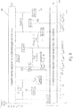
- FIG. 3 shows a flow diagram of a method 160 for sending data, according to an embodiment.
- the method 160 includes a step 162 of sending data in a first mode repeatedly using a first jump pattern and a second jump pattern.
- the method 160 further comprises a step 164 of sending data in a second mode once using a third jump pattern, the jump patterns of the first mode and the second mode being different.
- FIG. 3 shows a flow diagram of a method 170 for receiving data, according to an embodiment.
- the method 170 includes a step 172 of receiving data in a first mode repeatedly using a first hop pattern and a second hop pattern.
- the method 170 further comprises a step 174 of receiving data in a second mode once using a third jump pattern, the jump patterns of the first mode and the second mode being different.
- a method for generating jump patterns are described in more detail. Shows in detail Fig. 6 thereby a method for generating jump patterns for a simple (ie one time) transmission of data by means of a jump pattern while Fig. 7 shows a method for generating jump patterns for repeated transmission of data by means of two jump patterns.
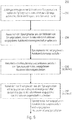
- FIG. 2 shows a flow diagram of a method 200 for generating a set of jump patterns, according to an exemplary embodiment.
- the method 200 comprises a step 202 of randomly generating a plurality of hopping patterns, the hopping patterns having at least two hops which are distributed in frequency and time.
- the method 200 further comprises a step 204 of selecting the jump patterns from the plurality of jump patterns, the autocorrelation functions of which have predetermined autocorrelation properties, in order to obtain jump patterns with predetermined autocorrelation properties.
- those jump patterns can meet the predefined autocorrelation properties, the autocorrelation function secondary maxima of which do not exceed a predefined minimum amplitude threshold value.
- the amplitude threshold value can, for example, be equal to a number of hops in a cluster be a plurality of clusters into which the hop pattern is divided.
- a cluster can, for example, be a number of hops that have the same time and / or frequency spacing from one another.
- those jump patterns can meet the predefined autocorrelation properties, the partial sum of which, formed over a predefined number of largest amplitude values of the respective autocorrelation function, is smaller than a predefined threshold value.
- the threshold value can be selected in such a way that at least two jump patterns (or a predefined number of jump patterns) meet the predefined autocorrelation properties.
- the method 200 can furthermore have a step 206 of calculating cross-correlation functions between the jump patterns with predetermined autocorrelation properties. Furthermore, the method 200 can have a step 208 of selecting the jump patterns from the jump patterns with predetermined autocorrelation properties, the cross-correlation functions of which have predetermined cross-correlation properties, in order to obtain jump patterns with predetermined autocorrelation properties and predetermined cross-correlation properties.
- those jump patterns can meet the predetermined cross-correlation properties, the partial sums of which are the smallest, formed over a predetermined number of largest amplitude values of the respective cross-correlation function.
- FIG. 10 shows a flow diagram of a method 210 for generating a first set of jump patterns and a second set of jump patterns.
- the method 210 comprises a step 212 of randomly generating a plurality of hopping patterns for the first set of hopping patterns and a plurality of hopping patterns for the second set of hopping patterns, the hopping patterns having at least two hops which are distributed in frequency and time, wherein the jump patterns for the first set of jump patterns and the jump patterns for the second set of jump patterns are different.
- the method 210 further comprises a step 214 of selecting the jump patterns from the plurality of jump patterns for the first set of jump patterns, the autocorrelation functions of which have predetermined autocorrelation properties in order to obtain jump patterns with predetermined autocorrelation properties for the first set of jump patterns, and selecting the jump patterns from the Multiple jump patterns for the second set of jump patterns, their autocorrelation functions have predetermined autocorrelation properties in order to obtain jump patterns with predetermined autocorrelation properties for the second set of jump patterns.
- a time interval between the jumps in the jump patterns for the second set of jump patterns can be at least as great as a temporal length of one of the jumps in the jump patterns for the first set of jump patterns.
- the shortest time interval between two sub-data packets can be maximized. This would be (T_Frame - N ⁇ T_Burst) / (N-1), i.e. an equidistant temporal distribution of the bursts (within the clusters and between the clusters). Since this regularity is of course not optimal for the design process, a slight jitter can be inserted.
- those jump patterns can meet the predefined autocorrelation properties, the autocorrelation function secondary maxima of which do not exceed a predefined minimum amplitude threshold value.
- the amplitude threshold value can, for example, be equal to a number of hops in a cluster of a plurality of clusters into which the jump pattern is divided.
- a cluster can, for example, be a number of hops that have the same time and / or frequency spacing from one another.
- those jump patterns can meet the predefined autocorrelation properties, the partial sum of which, formed over a predefined number of largest amplitude values of the respective autocorrelation function, is smaller than a predefined threshold value.
- the threshold value can be selected in such a way that at least two jump patterns (or a predefined number of jump patterns) meet the predefined autocorrelation properties.
- the method 210 can furthermore have a step 216 of calculating cross-correlation functions between the jump patterns with predetermined autocorrelation properties for the first set of jump patterns and of cross-correlation functions between the jump patterns with predetermined autocorrelation properties for the second set of jump patterns.
- the method can have a step 218 of selecting the jump patterns from the jump patterns with predetermined autocorrelation properties for the first set of jump patterns, the cross-correlation functions of which have predetermined cross-correlation properties, to jump patterns with predetermined Obtain autocorrelation properties and predetermined cross-correlation properties for the first set of jump patterns, and the jump pattern from the jump patterns with predetermined autocorrelation properties for the second set of jump patterns whose cross-correlation functions have predetermined cross-correlation properties to jump patterns with predetermined autocorrelation properties and predetermined cross-correlation properties for the second set of receive.
- those jump patterns can meet the predetermined cross-correlation properties, the partial sums of which are the smallest, formed over a predetermined number of largest amplitude values of the respective cross-correlation function.
- Jump patterns that match the in Fig. 6 or Fig. 7 The method shown can be used, for example, in a system for unidirectional or bidirectional data transmission from many sensor nodes to a base station using the so-called “Telegram Splitting Multiple Access (TSMA)" access method.
- TSMA Transmission Splitting Multiple Access
- TSMA Time Division Multiple Access
- the bursts 142 can be distributed according to a real or a pseudo-random principle both over time and over the available frequencies.
- This telegram splitting approach provides a particularly high level of robustness with regard to interference from other sensor nodes, regardless of whether they come from your own or external systems.
- the interference robustness in the own sensor nodes is achieved in particular by distributing the various user signal bursts as evenly as possible over the time range as well as the frequency range.
- This random distribution can be achieved through various measures, such as (1) through unavoidable tolerance deviations of the crystal reference oscillator with regard to the frequency, (2) through the random asynchronous channel access there is any granularity in the time domain, and (3) through different burst arrangements of the different sensor nodes to different jump patterns.
- the sub-data packets can be sent at least twice, staggered in time, e.g. in hopping patterns that are as different as possible and e.g. in as different frequency bands as possible. Since only one transmitter is available in the sensor node for the transmission of the signal, certain restrictions result for the interleaved repetition with regard to the temporal burst arrangement in the jump pattern. The way in which the first and second transmission are interleaved in the case of repetition will be explained in more detail later.
- the diverse redundant signals can be combined on the receiving side, for example, in all possible forms, such as maximum ratio combining (MRC), equal gain combining, scanning / switching combining or selection combining.
- MRC maximum ratio combining
- equal gain combining scanning / switching combining
- selection combining selection combining
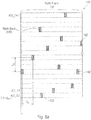
- the individual bursts of a data packet 120 (hereinafter also referred to as a frame), as in FIG Figure 8a shown, both over time and over frequencies.
- FIG. 8a Shows in detail Figure 8a
- a structure of a frame 120 with a TSMA hopping pattern 140 The ordinate describes the frequency or channels (frequency channels) and the abscissa describes the time.
- the start time T 0 of a frame 120 with the total duration T frame is selected at random by the sensor node 100 on the basis of the asynchronous transmission.
- the duration T burst of a burst 142 can vary and is assumed to be constant in the following without restricting general validity, whereas the time intervals t n. (N + 1) , which are the distance between two adjacent burst centers (here the two bursts with the indices n and n + 1), each being random variables, which are all within a predeterminable range T A_mln ⁇ t n, (n + 1) T A_max for n ⁇ ⁇ 1,2, ..., N-1 ⁇ .
- N is the number of bursts 142 within a frame 120.
- the Frequency separation f n. (N + 1) between 2 bursts 142 is a multiple of the carrier spacing B c used in TSMA and is therefore independent of the symbol rate S R used . ( S R ⁇ B C ).
- the relative start frequency of a frame is denoted by fo.
- the number of available frequency channels is given as L and N ⁇ L applies. In this respect, there are usually more or exactly as many frequency channels as are required by the N bursts 142 and, within a frame 120, each of the N bursts 142 is therefore located in a different frequency channel.
- the frequencies used by the N bursts do not have to be contiguous, but can be distributed as desired within the L available frequencies.
- TSMA pattern The arrangement of the N bursts 142 in terms of time and frequency is referred to below as a TSMA pattern (TSMA hop pattern). If this jump pattern is known to the receiver, then the receiver can synchronize with it on the basis of the pilot sequences located in some or each burst 142 and then decode the received data.
- the frequency deviation of the oscillator from its nominal frequency can be taken into account.
- the frequency deviation can be a multiple of the carrier spacing B c . Since this frequency offset can assume both positive and negative values, a security strip 156 of S frequency channel, in which there is no burst (see also FIG Fig. 9 ). In this respect, the degree of freedom for the individual bursts of the hopping pattern is reduced to (L-2 ⁇ S) frequencies, where N (L-2 ⁇ S) still applies.
- the receiver 110 Due to the temporally asynchronous transmission, the receiver 110 does not know when a transmitter 100 is transmitting and which transmitter is transmitting with which hopping pattern is also unknown to the receiver.
- the detection of a signal would involve considerable additional effort if the pattern arrangement, that is to say the grouping of the N bursts 142 within the time range T frame and over the (L-2 ⁇ S) frequencies, were completely random.
- C successive bursts 142 can be combined to form a so-called cluster 148, which are, for example, identical with respect to their time and frequency intervals relative to one another.
- a jump pattern 140 thus consists of N / C clusters 148, each with C bursts 142.
- C can advantageously be selected in such a way that it is an integer divisor of N. So it applies N / C.
- N ⁇ ⁇ k ⁇ Z : k ⁇ N / C. N .
- the duration T burst of a burst 142 is relatively short at the transmission time T frame of the entire frame 120. If the first burst has been sent, it is left 142 a certain minimum time T A_min elapses, this can have certain advantages with regard to the power consumption of the battery-operated sensor nodes (recovery time of the battery after a comparatively energy-intensive transmission process). This minimum distance T A_min should also be complied with as a design specification, if possible within the clusters and between the clusters.
- time and frequency diversity can now optionally be used in the form of nested repetitions when sending the user data.
- the new jump patterns for repeatedly transmitted data can optionally match the jump patterns for single transmitted data, i.e. have the lowest possible cross-correlation.
- the TSMA hopping pattern should a) be robust against external disturbances from other systems (here neither the bandwidth nor the duration of the disturbance is known), as well as b) against internal disturbances System.
- c) it can be made as easy as possible for the recipient to distinguish between programs with and without repetition, especially when using maximum ratio combining.
- Aspects a) and c) are independent of the design process and can be specified in advance. Improved or even maximum immunity to external interference can be achieved, for example, by placing the two frames to be repeated in two different frequency bands (each with their L frequency channels). The greater the frequency spacing (see Figure 8b ), the lower the probability that an external interferer can interfere with both frames at the same time.
- Figure 8b Shows in detail Figure 8b in a diagram, an occupancy of two frequency channels 150_1 and 150_2 during the repeated transmission of data by means of a first jump pattern 140_1 and a second jump pattern 140_2.
- the ordinate describes the frequency and the abscissa describes the time.
- Figure 8b shows an interleaved frame transmission with repetition using two different frequency bands.
- the receiver can, for example, use the jump pattern to differentiate between transmissions with and without repetition if different jump patterns are used for both types of transmission.
- the jump patterns shown in section 3.2 can be used and for transmissions with repetition, for example, the jump patterns shown in section 3.3 can be used.
- a different (new) jump pattern can be used for the first transmission in repeat mode than for the second transmission. It has been shown, however, that with appropriate measures described below, the use of a single jump pattern is sufficient for all transmissions in the repetition mode. In addition, this measure also makes it easier for the receiver to jointly recognize the individual bursts with the same pattern in the repetition mode.
- the jump patterns to be used for the case of repetition also have (somewhat) different time intervals between the bursts in the cluster, then the average number of hits can be reduced again.
- the following examines the immunity to interference of transmitters that each use the same jump pattern in repeat mode. If two transmitters with identical jump patterns were to be used at the same point in time T 0 (see Figure 8b ) start in the same frequency band, then without any countermeasures there would be a complete superposition of all 2N bursts in both frames of the repeat mode. Such a situation can be prevented almost entirely by varying the parameters.
- a variety can be achieved through the introduction of a variable, multi-stage time offset T W (see Figure 2), or the random start of the first burst in one of the two frequency bands A or B.
- a random positive or negative frequency offset (for example in multiples of the carrier spacing B C ) can also be applied to the TSMA pattern.
- Fig. 9 shows a schematic view of a structure of a TSMA hopping pattern 142.
- the ordinate describes the frequency in frequency channels and the abscissa describes the time.
- Fig. 9 shows a structure of the TSMA hopping pattern 142 with cluster arrangement and frequency occupancy.
- the 3 bursts in the 8 clusters can each have the same frequency spacing relative to one another, at least 8 additional frequency bands can be reserved, leaving a maximum of 28 frequency bands for the base allocation of the 3 bursts. For example, any relative assignment with 3 different frequency bands can be made.
- the largest possible frequency deviation for adjacent bursts as is the case, for example, with the base assignments (1,28,14) or (1,24,12), proves to be advantageous with regard to the later optimizations.
- the assignment of the individual clusters to one another can also take place at random.
- the message is broken down into many small bursts 142 in accordance with the jump pattern 140, both in time and in frequency direction.
- the bursts 142 are smeared both over time and over the available frequency spectrum. If all sensor nodes 100 have the same jump pattern, then with increasing number of participants it happens more and more often that bursts of different participants overlap in time (in the worst case completely) and thus interfere with one another. The more bursts 142 are disturbed by bursts from other users within a frame 120, the greater the probability that the receiver-side error correction will fail and transmission errors will occur.
- Embodiments create a set of hopping patterns which ideally minimize the packet error rate (frame or packet error rate, FER, PER) of the radio transmission system. This is done on the assumption that all radio subscribers use the same set of jump patterns. While only a finite (albeit usually relatively large) number of permutations is possible with regard to the arrangement of the radio frequencies in a hopping pattern through the introduction of discrete radio channels, the temporal arrangement of the bursts 142 due to a continuous time axis leads to an extremely large number of permutation possibilities, ie Jump patterns. This means that a "full search" over all possible jump patterns is almost impossible.
- packet error rate frame or packet error rate, FER, PER
- the method on which the invention is based is therefore based on a Monte Carlo approach, which uses suitable design criteria to select a set with the best properties in terms of an expected minimum error rate from a very large number of (pseudo) randomly generated jump patterns.
- the number of jump patterns in this set is P selection .
- a metric is required which ideally has a strictly monotonous relationship with the expected packet error rate, the minimization of which therefore ideally minimizes the packet error rate.
- the two-dimensional (2D) autocorrelated or cross-correlated of the jump pattern can be considered as a design criterion.
- the frequency index f in the AKF extends from -2S to + 2S.
- the time index t runs from -T frame to T frame , in steps of T frame / T A.
- the AKF dimension of ⁇ x, x is therefore (4S + 1) x (2M + 1).
- the influence of adjacent channel interference can also be taken into account in the time and frequency information matrix X. This is important when the reception filters in the receiver 110 do not have any particular sharpness (selectivity) with regard to adjacent channel interference.
- a metrics vector m Met ⁇ co-channel, 1st adjacent channel, 2nd adjacent channel, ... ⁇ can be introduced, which inserts the corresponding information into the X matrix.
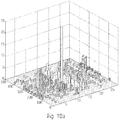
- Figure 10a and 10b show two ACF examples.
- the lower this threshold the fewer bursts are disturbed in a frame and the probability of a transmission error decreases.
- Figure 10b shows a less favorable jump pattern in which the threshold value is, for example, clearly exceeded in some places. This increases the likelihood of transmission errors.
- P optimal candidates of the jump patterns can be generated whose AKF secondary maxima do not exceed a predetermined minimum amplitude threshold value N threshold ⁇ C ( C is the cluster size).
- N threshold ⁇ C C is the cluster size.
- the generation of candidates for the jump patterns takes place within the framework of a Monte Carlo simulation, in which jump patterns with random time and frequency patterns (within the framework of the boundary conditions mentioned, see above) are generated. If threshold > C applies to the threshold value N , the number of values that exceed the value C should be as small as possible.
- the (4S + 1) x (2M + 1) elements of the 2D autocorrelated ⁇ x, x can be sorted in ascending order in a vector V Sort. Since the total over all AKF elements for all jump patterns is always approximately constant and most AKF elements have values of 0, 1 or C (complete cluster collision), only the values greater than C, if any, are of interest. In this respect, it is sufficient assumes that only the last v AKF elements of V Sort , i.e. V Sort (end- v AKF + 1: end) are considered.
- the first design step can be repeated with a new set of parameters.
- the first design step the finding of P 1 optimal candidates of a set of jump pattern patterns, takes place completely independently of the finding of P 2 optimal candidates of another pattern set.
- all parameter specifications for the patterns clusters, frequency patterns, time intervals, etc.
- the design parameters N threshold , V sort , number of rows and columns of the 2D AKF ⁇ x, x , etc.
- 2D-KKF 2D cross-correlation matrices
- the time index of ⁇ x, y runs unchanged in steps of T frame / T A from - T frame to T frame.
- the KKF frequency index f generally extends from - (S x + S y ) to + (S x + S y ), since the two jump patterns under consideration can have different deviations in their frequency error behavior (oscillator frequency deviations).
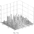
- Figure 11a and 11b again show two 2D KKF examples, a favorable case ( Figure 11a ) and an unfavorable case ( Figure 11b ).
- the different candidate sets (P 1 Optimal and P 2 Optimal ) are processed one after the other and a square matrix O vKKF of Dimension (( P 1 Optimal + P 2 Optimal ) x ( P 1 Optimal + P 2 Optimal )), which contains all cross-correlation sequences ⁇ x, y of all possible combinations.
- the aim is to search for the P selection of different jump patterns 142 which among one another have the most favorable 2D KKF properties, since these correlate with a comparatively low maximum number of colliding bursts in a frame.
- the properties of ((P selection -1) ⁇ P selection ) / 2 different 2D KKF can be evaluated using the stored sums SUM KKF in the matrix O vKKF .
- Those P selection of different jump patterns whose total sum over the (( P selection -1) ⁇ P selection ) / 2 different partial sums SUM KKF from O vKKF results in a minimum yields the optimal P selection jump patterns.
- P selection jump pattern can always be selected randomly from the P optimal jump patterns
- FIG. 12 Shows in detail Fig. 12 a flowchart of a method 260 for generating jump patterns, according to an embodiment.
- a first step 262 the method 260 is started.
- n is set equal to one, where n is a run variable.
- a jump pattern can be generated randomly.
- the above-mentioned degrees of freedom with regard to the frequency channel occupancy such as, for example, a frequency channel assignment of the bursts with a basic assignment of the bursts within the cluster and an assignment of the clusters to one another, can be taken into account.
- the above-mentioned degrees of freedom with regard to the time intervals such as, for example, a determination of the time intervals within the cluster and between the clusters, can be taken into account.
- the autocorrelation function of the randomly generated jump pattern can be calculated.
- a 2D AKF calculation ⁇ x, x (f, t) can be carried out.
- the 2D AKF values can be sorted in a vector v Sort.
- a fifth step 270 it can be determined whether the randomly generated jump pattern has the predetermined autocorrelation properties. For example, it can be determined whether the AKF secondary maxima of the jump pattern do not exceed a specified minimum amplitude threshold value N Threshold ⁇ C ( C is the cluster size); in detail, it can be determined whether the sum SUM AKF of these v AKF elements (partial sum) does not exceed the sum threshold of S Sum_AKF_Schwelle of, for example, (v AKF -1) ⁇ C + N.
- the third step is repeated. If the jump pattern has the predetermined autocorrelation properties, then the method is continued.
- a seventh step 274 it can be checked whether an optimal number P optimal of jump patterns is available.
- step 276 it is determined whether a new set of jump patterns should be generated. If so, then the second step 264 is repeated. If not, then the procedure continues. It can also be determined whether a further set of jump patterns should optionally be generated for a different set of parameters, such as a different oscillator offset or a different cluster appearance with changed time intervals or frequency jumps.
- a ninth step 278, the cross-correlation functions between the jump patterns with predetermined autocorrelation properties are calculated.
- n can be set equal to one and GS threshold can be set to a large threshold, such as 10 6 , for example.
- P are newly and randomly 1 Optimal existing first hopping patterns and P 2 selection hopping pattern randomly selected new and 1 selection from the hopping pattern P of the P 2 optimal existing second hopping patterns.
- P 1 optimally different numbers are thrown out in random order
- F 1 randperm (1: P 1 optimal )
- P 2 optimally different numbers are thrown out in random order
- F 2 randperm (1: P 2 optimal ).
- the first P 1 selection can be selected
- Pattern1 selection F (1: P 1 selection )
- the first P 2 selection can be selected
- Pattern2 selection F (1: P 2 selection ).
- the selected jump pattern can be saved.
- jump patterns are described by way of example that were generated with the above-mentioned method.
- a time hopping pattern, a frequency hopping pattern or a combination of a time hopping pattern and the frequency hopping pattern can be used for the individual transmission of data by means of a hopping pattern.
- the time jump pattern can be one of the eight time jump patterns listed in the following table, each with 24 jumps:
- each row is a time jump pattern, each column in the table being a jump of the respective time jump pattern starting from a second jump, so that each time jump pattern has 24 jumps, with each cell in the table having a time interval of a reference point of the respective jump to the same reference point of an immediately following jump in - preferably multiples of - symbol durations.
- the frequency hopping pattern can be one of the eight frequency hopping patterns listed in the following table, each with 24 hops:
- each row is a frequency hopping pattern, with each column in the table being a hop of the respective frequency hopping pattern, with each cell in the table specifying a transmission frequency of the respective hop of the respective frequency hopping pattern in carriers from UCG_C0 to UCG_23.
- the respective time hopping pattern and the respective frequency hopping pattern in the respective table can have the same line number.
- a time hop pattern, a frequency hop pattern or a combination of a time hop pattern and the frequency hop pattern can be used for the repeated transmission of data by means of two hopping patterns (e.g. first hopping pattern and second hopping pattern).
- the time jump pattern can be one of the eight time jump patterns listed in the following table, each with 24 jumps:
- each row is a time jump pattern, with each column in the table being a jump of the respective time jump pattern starting from a second jump, so that each time jump pattern has 24 jumps, with each cell in the table having a time interval from a reference point of the respective jump indicates a same reference point of an immediately following jump in - preferably multiples of - symbol durations.
- the frequency hopping pattern can be one of the eight frequency hopping patterns listed in the following table, each with 24 hops:
- each row is a frequency hopping pattern, with each column in the table being a hop of the respective frequency hopping pattern, with each cell in the table specifying a transmission frequency of the respective hop of the respective frequency hopping pattern in carriers from UCG_C0 to UCG_23.
- the respective time hopping pattern and the respective frequency hopping pattern in the respective table can have the same line number.
- embodiments of the invention can be implemented in hardware or in software.
- the implementation can be carried out using a digital storage medium such as a floppy disk, a DVD, a Blu-ray disk, a CD, a ROM, a PROM, an EPROM, an EEPROM or a FLASH memory, a hard disk or other magnetic memory or optical memory are carried out on the electronically readable control signals are stored, which can interact with a programmable computer system or cooperate in such a way that the respective method is carried out. Therefore, the digital storage medium can be computer readable.
- Some exemplary embodiments according to the invention thus include a data carrier which has electronically readable control signals which are capable of interacting with a programmable computer system in such a way that one of the methods described herein is carried out.
- exemplary embodiments of the present invention can be implemented as a computer program product with a program code, the program code being effective to carry out one of the methods when the computer program product runs on a computer.
- the program code can, for example, also be stored on a machine-readable carrier.
- exemplary embodiments include the computer program for performing one of the methods described herein, the computer program being stored on a machine-readable carrier.
- an exemplary embodiment of the method according to the invention is thus a computer program which has a program code for performing one of the methods described herein when the computer program runs on a computer.
- a further exemplary embodiment of the method according to the invention is thus a data carrier (or a digital storage medium or a computer-readable medium) on which the computer program for performing one of the methods described herein is recorded.
- the data carrier, the digital storage medium or the computer-readable medium are typically tangible and / or non-perishable or non-transitory.
- a further exemplary embodiment of the method according to the invention is thus a data stream or a sequence of signals which represents or represents the computer program for performing one of the methods described herein.
- the data stream or the sequence of signals can, for example, be configured to be transferred via a data communication connection, for example via the Internet.
- Another exemplary embodiment comprises a processing device, for example a computer or a programmable logic component, which is configured or adapted to carry out one of the methods described herein.
- a processing device for example a computer or a programmable logic component, which is configured or adapted to carry out one of the methods described herein.
- Another exemplary embodiment comprises a computer on which the computer program for performing one of the methods described herein is installed.
- a further exemplary embodiment according to the invention comprises a device or a system which is designed to transmit a computer program for performing at least one of the methods described herein to a receiver.
- the transmission can take place electronically or optically, for example.
- the receiver can be, for example, a computer, a mobile device, a storage device or a similar device.
- the device or the system can comprise, for example, a file server for transmitting the computer program to the recipient.
- a programmable logic component for example a field-programmable gate array, an FPGA
- a field-programmable gate array can interact with a microprocessor in order to carry out one of the methods described herein.
- the methods in some exemplary embodiments are implemented by any one Hardware device performed. This can be hardware that can be used universally, such as a computer processor (CPU), or hardware specific to the method, such as an ASIC, for example.
- the devices described herein can be implemented, for example, using a hardware apparatus, or using a computer, or using a combination of a hardware apparatus and a computer.
- the devices described herein, or any components of the devices described herein, can be implemented at least partially in hardware and / or in software (computer program).
- the methods described herein can be implemented using hardware apparatus, or using a computer, or using a combination of hardware apparatus and a computer.
Abstract
Bei Ausführungsbeispielen nutzen Datensender und Datenempfänger in einem ersten Modus für eine wiederholte Übertragung von Daten ein erstes Sprungmuster und ein zweites Sprungmuster und in einem zweiten Modus für die einfache Übertragung von Daten ein drittes Sprungmuster, wobei die Sprungmuster des ersten Modus und des zweiten Modus unterschiedlich sind, so dass eine Kollisionswahrscheinlichkeit bei der gleichzeitigen Übertragung von Daten durch einen weiteren Datensender in einem jeweils anderen Modus verringert und somit die Übertragungssicherheit erhöht werden kann.In exemplary embodiments, data transmitters and data receivers use a first jump pattern and a second jump pattern in a first mode for repeated transmission of data and a third jump pattern in a second mode for simple transmission of data, the jump patterns of the first mode and the second mode being different so that the probability of a collision when data is transmitted simultaneously by a further data transmitter in a different mode can be reduced and the transmission reliability can be increased.
Description
Ausführungsbeispiele beziehen sich auf einen Datensender und ein Verfahren zum Betrieb desselben. Weitere Ausführungsbeispiele beziehen sich auf einen Datenempfänger und ein Verfahren zum Betrieb desselben. Weitere Ausführungsbeispiele beziehen sich auf eine Erzeugung von spezifischen Sprungmustern für eine wiederholte Aussendung von Daten. Weitere Ausführungsbeispiele beziehen sich auf ein wiederholtes Senden und Empfangen von Daten unter Verwendung von spezifischen Sprungmustern. Manche Ausführungsbeispiele beziehen sich auf einen Optimierungsprozess zur Generierung von Sprungmustern (engl. hopping-pattern) zur Verwendung bei verschachtelten Wiederholungen.Exemplary embodiments relate to a data transmitter and a method for operating the same. Further exemplary embodiments relate to a data receiver and a method for operating the same. Further exemplary embodiments relate to the generation of specific jump patterns for repeated transmission of data. Further exemplary embodiments relate to repeated transmission and reception of data using specific jump patterns. Some exemplary embodiments relate to an optimization process for generating hopping patterns for use in interleaved repetitions.
Aus
In der
In der Veröffentlichung [
In der Veröffentlichung [
Das Telegram-Splitting-Verfahren nutzt bestimmte Zeit-Frequenz-Sprungmuster zur Übertragung von Daten über den Funkkanal. Um ein Datenpaket erfolgreich decodieren zu können, ist es notwendig, dass das Sprungmuster, das zum Versenden verwendet wurde, am Empfänger bekannt ist. Um dies zu gewährleisten sind für Telegram-Splitting-Netzwerke globale Zeit- und Frequenzsprungmuster definiert, die allen Teilnehmern bekannt sind.The telegram splitting process uses certain time-frequency hopping patterns to transmit data over the radio channel. In order to be able to decode a data packet successfully, it is necessary that the jump pattern that was used for sending is known at the receiver. To ensure this, global time and frequency hopping patterns are defined for telegram splitting networks that are known to all participants.
Bei der Kommunikation mehrerer Teilnehmer mittels Telegram-Splitting im gleichen Band ergibt sich eine schlechtere Störfestigkeit der Übertragung, wenn das gleiche Zeit und/oder Frequenzsprungmuster für die Datenübertragung von mehreren Knoten genutzt wird. Starten zwei Knoten innerhalb eines kurzen Zeitfensters (z.B. die Dauer eines Sub-Datenpakets) eine Übertragung mit dem gleichen Sprungmuster, so überlagern sich alle Sub-Datenpakete des Telegramms und löschen sich im schlechtesten Fall gegenseitig aus.When several participants communicate by means of telegram splitting in the same band, the transmission is less immune to interference if the same time and / or frequency hopping pattern is used for data transmission by several nodes. If two nodes start a transmission with the same jump pattern within a short time window (e.g. the duration of a sub-data packet), then all sub-data packets of the telegram overlap and in the worst case delete each other.
Die
Die Druckschrift
In der Veröffentlichung [
Der vorliegenden Erfindung liegt somit die Aufgabe zugrunde, ein Konzept zu schaffen, welches die Übertragungssicherheit erhöht, wenn mehrere Knoten ein Zeit- und/oder Frequenzsprungmuster für die Datenübertragung nutzen.The present invention is therefore based on the object of creating a concept which increases the transmission security when several nodes use a time and / or frequency hopping pattern for the data transmission.
Diese Aufgabe wird durch die unabhängigen Patentansprüche gelöst.This problem is solved by the independent patent claims.
Vorteilhafte Weiterbildungen finden sich in den abhängigen Patentansprüchen.Advantageous further developments can be found in the dependent claims.
Ausführungsbeispiele schaffen einen Datensender, der ausgebildet ist, um Daten in einem ersten Modus wiederholt unter Verwendung eines ersten Sprungmusters und eines zweiten Sprungmusters auszusenden, wobei der Datensender ausgebildet ist, um Daten in einem zweiten Modus einmal unter Verwendung eines dritten Sprungmusters auszusenden, wobei die Sprungmuster des ersten Modus und des zweiten Modus unterschiedlich sind.Embodiments provide a data transmitter which is designed to transmit data in a first mode repeatedly using a first jump pattern and a second jump pattern, the data transmitter being designed to transmit data in a second mode once using a third jump pattern, the jump pattern of the first mode and the second mode are different.
Weitere Ausführungsbeispiele schaffen einen Datenempfänger, der ausgebildet ist, um in einem ersten Modus Daten unter Verwendung eines ersten Sprungmusters und eines zweiten Sprungmusters wiederholt zu empfangen, wobei der Datenempfänger ausgebildet ist, um in einem zweiten Modus Daten unter Verwendung eines dritten Sprungmusters einmal zu empfangen, wobei die Sprungmuster des ersten Modus und des zweiten Modus unterschiedlich sind.Further exemplary embodiments provide a data receiver which is designed to repeatedly receive data in a first mode using a first jump pattern and a second jump pattern, the data receiver being designed to receive data once in a second mode using a third jump pattern, wherein the jump patterns of the first mode and the second mode are different.
Bei Ausführungsbeispielen nutzen Datensender und Datenempfänger in einem ersten Modus (=Wiederholungsaussendungsmodus) für eine wiederholte Übertragung von Daten ein erstes Sprungmuster und ein zweites Sprungmuster und in einem zweiten Modus (=Einzelaussendungsmodus) für die einfache Übertragung von Daten ein drittes Sprungmuster, wobei die Sprungmuster des ersten Modus und des zweiten Modus unterschiedlich sind. Hierdurch kann eine Kollisionswahrscheinlichkeit bei der gleichzeitigen Übertragung von Daten durch einen weiteren Datensender in einem anderen Modus verringert werden und somit die Übertragungssicherheit erhöht werden.In exemplary embodiments, data transmitters and data receivers use a first jump pattern and a second jump pattern in a first mode (= repeat transmission mode) for repeated transmission of data and a third jump pattern in a second mode (= single transmission mode) for simple transmission of data, with the jump pattern of the first mode and second mode are different. This can reduce the likelihood of a collision during the simultaneous transmission of data by a further data transmitter in a different mode and thus increase the transmission reliability.
Bei Ausführungsbeispielen kann der Datenempfänger ausgebildet sein, um eine wiederholte Übertragung von Daten anhand des ersten Sprungmusters und/oder des zweiten Sprungmusters zu erkennen, und um eine einfache Übertragung von Daten anhand des dritten Sprungmusters zu erkennen.In embodiments, the data receiver can be designed to recognize a repeated transmission of data using the first jump pattern and / or the second jump pattern, and to recognize a simple transmission of data using the third jump pattern.
Bei Ausführungsbeispielen kann der Datenempfänger ausgebildet sein, um eines der zwei Sprungmuster (z.B. das erste Sprungmuster) in einem Empfangsdatenstrom zu detektieren, um die mit dem einem Sprungmuster übertragenen Daten zu empfangen, wobei der Datenempfänger ausgebildet sein kann, um das andere Sprungmuster (z.B. zweites Sprungmuster) in dem Empfangsdatenstrom unter Verwendung des bereits detektierten Sprungmusters (z.B. erstes Sprungmuster) zu ermitteln, um die mit dem anderen Sprungmuster (z.B. zweites Sprungmuster) übertragenen Daten zu empfangen. Die mit dem ersten Sprungmuster übertragenen Daten und die mit dem zweiten Sprungmuster übertragenen Daten sind durch die Wiederholung gleich.In exemplary embodiments, the data receiver can be designed to detect one of the two jump patterns (e.g. the first jump pattern) in a receive data stream in order to receive the data transmitted with the one jump pattern Jump pattern) in the received data stream using the already detected jump pattern (e.g. first jump pattern) in order to receive the data transmitted with the other jump pattern (e.g. second jump pattern). The data transmitted with the first jump pattern and the data transmitted with the second jump pattern are the same due to the repetition.
Bei Ausführungsbeispielen können das erste Sprungmuster und das zweite Sprungmuster aus einem ersten Satz von Sprungmustern ausgewählt werden, während das dritte Sprungmuster aus einem zweiten Satz von Sprungmustern ausgewählt werden kann. Der erste Satz von Sprungmustern und der zweite Satz von Sprungmustern können unterschiedlich sein.In exemplary embodiments, the first jump pattern and the second jump pattern can be selected from a first set of jump patterns, while the third jump pattern can be selected from a second set of jump patterns. The first set of jump patterns and the second set of jump patterns can be different.
Beispielsweise kann der Datensender oder der Datenempfänger für die Übertragung von Daten in dem ersten Modus das erste Sprungmuster und das zweite Sprungmuster aus der ersten Klasse von Sprungmustern auswählen, während ein weiterer Datensender für die Übertragung von Daten in dem zweiten Modus ein Sprungmuster aus der zweiten Klasse von Sprungmustern auswählen kann. Da die erste Klasse von Sprungmustern und die zweite Klasse von Sprungmustern unterschiedlich sind, kann sichergestellt werden, dass selbst bei einer zeitgleichen oder zumindest zeitlich überlappenden Übertragung von Daten durch den Datensender und den weiteren Datensender die Kollisionswahrscheinlichkeit so gering wie möglich gehalten werden kann.For example, the data transmitter or the data receiver can select the first jump pattern and the second jump pattern from the first class of jump patterns for the transmission of data in the first mode, while a further data transmitter for the transmission of data in the second mode can select a jump pattern from the second class can choose from jump patterns. Since the first class of jump patterns and the second class of jump patterns are different, it can be ensured that even with a simultaneous or at least temporally overlapping transmission of data through the Data transmitter and the other data transmitter, the probability of a collision can be kept as low as possible.
Bei Ausführungsbeispielen kann, zum Aufbau einer Verbindung zwischen Datensender und Datenempfänger, sowohl im ersten Modus das erste Sprungmuster und das zweite Sprungmuster also auch im zweiten Modus das dritte Sprungmuster aus einem dritten Satz von Sprungmustern ausgewählt werden. Der dritte Satz von Sprungmustern kann eine Untermenge des ersten Satzes von Sprungmustern oder des zweiten Satzes von Sprungmustern sein, oder sich von diesen unterscheiden.In exemplary embodiments, in order to establish a connection between the data transmitter and the data receiver, the first jump pattern and the second jump pattern can be selected from a third set of jump patterns in the second mode as well. The third set of jump patterns can be a subset of the first set of jump patterns or the second set of jump patterns, or can differ from these.
Bei Ausführungsbeispielen können das erste Sprungmuster und das zweite Sprungmuster in zumindest einem aus der Frequenz und der Zeit zueinander verschoben sein, so dass das erste Sprungmuster und das zweite Sprungmuster zumindest teilweise ineinander verschachtelt sind.In exemplary embodiments, the first hop pattern and the second hop pattern can be shifted to one another in at least one of the frequency and the time, so that the first hop pattern and the second hop pattern are at least partially nested in one another.
Beispielsweise können sowohl das erste Sprungmuster als auch das zweite Sprungmuster Sprünge aufweisen, die in der Zeit und/oder Frequenz verteilt sind, so dass die Sprünge eines Sprungmusters in der Zeit und/oder Frequenz voneinander beabstandet sind, wobei das erste Sprungmuster und das zweite Sprungmuster in der Zeit und/oder Frequenz so zueinander verschoben sein können, dass zumindest ein Teil der Sprünge des zweiten Sprungmusters zwischen zumindest einem Teil der Sprünge des ersten Sprungmusters angeordnet sind. Zum Beispiel können die Sprünge des ersten Sprungmusters und die Sprünge des zweiten Sprungmusters in der Zeit abwechselnd angeordnet sein.For example, both the first jump pattern and the second jump pattern can have jumps that are distributed in time and / or frequency so that the jumps of a jump pattern are spaced from one another in time and / or frequency, the first jump pattern and the second jump pattern can be shifted relative to one another in terms of time and / or frequency such that at least some of the jumps of the second jump pattern are arranged between at least some of the jumps of the first jump pattern. For example, the jumps of the first jump pattern and the jumps of the second jump pattern can be arranged alternately in time.
Bei Ausführungsbeispielen können das erste Sprungmuster und das zweite Sprungmuster unterschiedlich sein. Beispielsweise können Sprünge des ersten Sprungmusters und Sprünge des zweiten Sprungmusters unterschiedlich in der Zeit und/oder Frequenz verteilt sein. Zum Beispiel können zwei aufeinander folgende Sprünge (z.B. erster Sprung und zweiter Sprung) des ersten Sprungmusters einen anderen Zeitabstand und/oder Frequenzabstand aufweisen als zwei aufeinander folgende Sprünge (z.B. erster Sprung und zweiter Sprung) des zweiten Sprungmusters.In exemplary embodiments, the first jump pattern and the second jump pattern can be different. For example, jumps in the first jump pattern and jumps in the second jump pattern can be distributed differently in terms of time and / or frequency. For example, two consecutive jumps (e.g. first jump and second jump) of the first jump pattern can have a different time interval and / or frequency interval than two consecutive jumps (e.g. first jump and second jump) of the second jump pattern.
Bei Ausführungsbeispielen kann das zweite Sprungmuster eine in der Frequenz und/oder Zeit verschobene Version des ersten Sprungmusters sein. Beispielsweise können das erste Sprungmuster und das zweite Sprungmuster gleich sein und nur in der Zeit und/oder Frequenz verschoben sein. Zum Beispiel können Sprünge des ersten Sprungmusters und Sprünge des zweiten Sprungmusters den gleichen relativen Zeitabstand und Frequenzabstand aufweisen. Bei Ausführungsbeispielen kann der Datensender ausgebildet sein, um das erste Sprungmuster und das zweite Sprungmuster in nur teilweise überlappenden oder unterschiedlichen Frequenzbändern auszusenden.In exemplary embodiments, the second hopping pattern can be a version of the first hopping pattern that is shifted in frequency and / or time. For example, the first hopping pattern and the second hopping pattern can be the same and only shifted in time and / or frequency. For example, jumps in the first jump pattern and jumps in the second jump pattern can have the same relative time interval and frequency interval. In exemplary embodiments, the data transmitter can be designed to transmit the first hopping pattern and the second hopping pattern in only partially overlapping or different frequency bands.
Bei Ausführungsbeispielen kann der Datensender ausgebildet sein, um das erste Sprungmuster oder das zweite Sprungmuster zufällig in einem von zumindest zwei unterschiedlichen Frequenzbändern zu senden, und um das andere Sprungmuster in dem anderen Frequenzband zu senden.In embodiments, the data transmitter can be designed to send the first hopping pattern or the second hopping pattern randomly in one of at least two different frequency bands, and to transmit the other hopping pattern in the other frequency band.
Bei Ausführungsbeispielen kann der Datensender ausgebildet sein, um einen Zeitoffset und/oder einen Frequenzoffset zwischen dem ersten Sprungmuster und dem zweiten Sprungmuster in Abhängigkeit von einem Betriebsparameter des Datensenders zu ermitteln. In diesem Fall kann dem Datenempfänger der Betriebsparameter des Datensenders entweder bekannt sein oder aber der Datenempfänger ist ausgebildet, um den Betriebsparameter zu ermitteln, z.B. zu schätzen oder mittels eines Hypothesentests zu berechnen.In embodiments, the data transmitter can be designed to determine a time offset and / or a frequency offset between the first hopping pattern and the second hopping pattern as a function of an operating parameter of the data transmitter. In this case, the data receiver can either know the operating parameters of the data transmitter or the data receiver is designed to determine the operating parameters, e.g. to estimate them or to calculate them by means of a hypothesis test.
Beispielsweise kann der Betriebsparameter des Datensenders ein immanenter Parameter des Datensenders selbst sein, wie z.B. eine Adressierungsinformation, eine Identifizierungsinformation, eine Quarztoleranz, ein Frequenzversatz oder eine verfügbare Sendeenergie.For example, the operating parameter of the data transmitter can be an intrinsic parameter of the data transmitter itself, such as addressing information, identification information, a quartz tolerance, a frequency offset or available transmission energy.
Beispielsweise kann der Betriebsparameter des Datensenders 100 ein dem Datensender 100 zugewiesener Parameter sein, wie z.B. ein zugewiesener Frequenzoffset, ein zugewiesener Zeitoffset, eine Funkzelle, eine geografische Position, eine Systemzeit oder eine Priorität des Datensenders oder der von dem Datensender zu sendenden Daten ist.For example, the operating parameter of the
Beispielsweise kann der Betriebsparameter des Datensenders 100 zumindest ein Teil von Nutzerdaten oder Fehlerschutzdaten sein.For example, the operating parameter of the
Beispielsweise kann der Betriebsparameter des Datensenders 100 ein zufälliger Frequenzoffset oder ein zufälliger Zeitoffset ist.For example, the operating parameter of the
Weitere Ausführungsbeispiele schaffen ein Verfahren zum Senden von Daten. Das Verfahren umfasst einen Schritt des Sendens von Daten in einem ersten Modus wiederholt unter Verwendung eines ersten Sprungmusters und eines zweiten Sprungmusters. Ferner umfasst das Verfahren einen Schritt des Sendens von Daten in einem zweiten Modus einmal unter Verwendung eines dritten Sprungmusters, wobei die Sprungmuster des ersten Modus und des zweiten Modus unterschiedlich sind.Further exemplary embodiments create a method for sending data. The method includes a step of sending data in a first mode repeatedly using a first jump pattern and a second jump pattern. The method further comprises a step of sending data in a second mode once below Use of a third jump pattern, the jump patterns of the first mode and the second mode being different.
Weitere Ausführungsbeispiele schaffen ein Verfahren zum Empfangen von Daten, gemäß einem Ausführungsbeispiel. Das Verfahren umfasst einen Schritt des Empfangens von Daten in einem ersten Modus wiederholt unter Verwendung eines ersten Sprungmusters und eines zweiten Sprungmusters. Ferner umfasst das Verfahren einen Schritt des Empfangens von Daten in einem zweiten Modus einmal unter Verwendung eines dritten Sprungmusters, wobei die Sprungmuster des ersten Modus und des zweiten Modus unterschiedlich sind.Further exemplary embodiments create a method for receiving data, according to an exemplary embodiment. The method includes a step of receiving data in a first mode repeatedly using a first hop pattern and a second hop pattern. The method further comprises a step of receiving data in a second mode once using a third jump pattern, the jump patterns of the first mode and the second mode being different.
Weitere Ausführungsbeispiele schaffen ein Verfahren zum Erzeugen eines ersten Satzes von Sprungmustern und eines zweiten Satzes von Sprungmustern. Das Verfahren umfasst einen Schritt des zufälligen Erzeugens einer Mehrzahl von Sprungmustern für den ersten Satz von Sprungmustern und einer Mehrzahl von Sprungmustern für den zweiten Satz von Sprungmustern, wobei die Sprungmuster zumindest zwei Sprünge aufweisen, die in der Frequenz und Zeit verteilt sind, wobei die Sprungmuster für den ersten Satz von Sprungmustern und die Sprungmuster für den zweiten Satz von Sprungmustern unterschiedlich sind. Ferner umfasst das Verfahren einen Schritt des Auswählens der Sprungmuster aus der Mehrzahl von Sprungmustern für den ersten Satz von Sprungmustern, deren Autokorrelationsfunktionen vorgegebene Autokorrelationseigenschaften aufweisen, um für den ersten Satz von Sprungmustern Sprungmuster mit vorgegebenen Autokorrelationseigenschaften zu erhalten, und Auswählen der Sprungmuster aus der Mehrzahl von Sprungmustern für den zweiten Satz von Sprungmustern, deren Autokorrelationsfunktionen vorgegebene Autokorrelationseigenschaften aufweisen, um für den zweiten Satz von Sprungmustern Sprungmuster mit vorgegebenen Autokorrelationseigenschaften zu erhalten.Further exemplary embodiments provide a method for generating a first set of jump patterns and a second set of jump patterns. The method comprises a step of randomly generating a plurality of jump patterns for the first set of jump patterns and a plurality of jump patterns for the second set of jump patterns, the jump patterns having at least two hops which are distributed in frequency and time, the jump patterns for the first set of jump patterns and the jump patterns for the second set of jump patterns are different. The method further comprises a step of selecting the jump pattern from the plurality of jump patterns for the first set of jump patterns, the autocorrelation functions of which have predetermined autocorrelation properties in order to obtain jump patterns with predetermined autocorrelation properties for the first set of jump patterns, and selecting the jump patterns from the plurality of Jump patterns for the second set of jump patterns, the autocorrelation functions of which have predetermined autocorrelation properties, in order to obtain jump patterns with predetermined autocorrelation properties for the second set of jump patterns.
Bei Ausführungsbeispielen kann ein zeitlicher Abstand der Sprünge der Sprungmuster für den zweiten Satz von Sprungmustern mindestens so groß sein wie eine zeitliche Länge eines der Sprünge der Sprungmuster für den ersten Satz von Sprungmustern.In exemplary embodiments, a time interval between the jumps in the jump patterns for the second set of jump patterns can be at least as great as a temporal length of one of the jumps in the jump patterns for the first set of jump patterns.
Bei Ausführungsbeispielen können zeitliche Abstände zwischen den Sprüngen der Sprungmuster innerhalb einer vorgegebenen Sprungmusterlänge mit einer Abweichung von ±20% äquidistant sein.In exemplary embodiments, the time intervals between the jumps in the jump patterns within a predetermined jump pattern length can be equidistant with a deviation of ± 20%.
Bei Ausführungsbeispielen kann das Verfahren einen Schritt des Abbildens der Mehrzahl von Sprungmustern für den ersten Satz von Sprungmustern in jeweils eine zweidimensionale Zeit- und Frequenzbelegungs-Matrix mit darauf angewandter Berechnung der Autokorrelationsfunktionen und des Abbildens der Mehrzahl von Sprungmustern für den zweiten Satz von Sprungmustern in jeweils eine zweidimensionale Zeit- und Frequenzbelegungs-Matrix mit darauf angewandter Berechnung der Autokorrelationsfunktionen aufweisen.In exemplary embodiments, the method can include a step of mapping the plurality of jump patterns for the first set of jump patterns into a two-dimensional time and frequency allocation matrix, with the calculation of the applied thereon Autocorrelation functions and the mapping of the plurality of jump patterns for the second set of jump patterns in each case a two-dimensional time and frequency allocation matrix with applied calculation of the autocorrelation functions.
Bei Ausführungsbeispielen kann der Schritt des Abbildens der Mehrzahl von Sprungmustern für den ersten Satz von Sprungmustern und/oder des Abbildens der Mehrzahl von Sprungmustern für den zweiten Satz von Sprungmustern jeweils unter Berücksichtigung eventuell auftretender Einflüsse von benachbarten Frequenzlagen (Nachbarkanalstörung) erfolgen.In exemplary embodiments, the step of mapping the plurality of hopping patterns for the first set of hopping patterns and / or mapping the plurality of hopping patterns for the second set of hopping patterns can take place in each case taking into account any influences from neighboring frequency positions (adjacent channel interference).
Bei Ausführungsbeispielen können die Autokorrelationsfunktionen zweidimensionale Autokorrelationsfunktionen sein.In exemplary embodiments, the autocorrelation functions can be two-dimensional autocorrelation functions.
Bei Ausführungsbeispielen können beim Auswählen der Sprungmuster für den ersten Satz von Sprungmustern diejenigen Sprungmuster die vorgegebenen Autokorrelationseigenschaften erfüllen, deren Autokorrelationsfunktions-Nebenmaxima einen vorgegebenen maximalen ersten Amplitudenschwellwert nicht überschreiten, und wobei beim Auswählen der Sprungmuster für den zweiten Satz von Sprungmustern diejenigen Sprungmuster die vorgegebenen Autokorrelationseigenschaften erfüllen, deren Autokorrelationsfunktions-Nebenmaxima einen vorgegebenen maximalen zweiten Amplitudenschwellwert nicht überschreiten.In embodiments, when selecting the jump patterns for the first set of jump patterns, those jump patterns can meet the specified autocorrelation properties whose secondary autocorrelation function maxima do not exceed a specified maximum first amplitude threshold value, and when the jump patterns for the second set of jump patterns are selected, those jump patterns meet the specified autocorrelation properties whose autocorrelation function secondary maxima do not exceed a predetermined maximum second amplitude threshold value.
Bei Ausführungsbeispielen kann der erste Amplitudenschwellwert gleich dem zweiten Amplitudenschwellwert sein.In embodiments, the first amplitude threshold value can be equal to the second amplitude threshold value.
Bei Ausführungsbeispielen kann der erste Amplitudenschwellwert gleich einer Anzahl von Sprüngen sein, die ein sich wiederholendes und in der Zeit und/oder Frequenz verschobenes Sub-Sprungmuster der jeweiligen Sprungmuster für den ersten Satz von Sprungmustern bilden, und wobei der zweiten Amplitudenschwellwert gleich einer Anzahl von Sprüngen ist, die ein sich wiederholendes und in der Zeit und/oder Frequenz verschobenes Sub-Sprungmuster der jeweiligen Sprungmuster für den zweiten Satz von Sprungmustern bilden.In exemplary embodiments, the first amplitude threshold value can be equal to a number of jumps that form a repetitive and in time and / or frequency shifted sub-jump pattern of the respective jump patterns for the first set of jump patterns, and the second amplitude threshold value equal to a number of jumps which form a repetitive and in time and / or frequency shifted sub-jump pattern of the respective jump patterns for the second set of jump patterns.
Bei Ausführungsbeispielen können beim Auswählen der Sprungmuster für den ersten Satz von Sprungmustern diejenigen Sprungmuster die vorgegebenen Autokorrelationseigenschaften erfüllen, deren Teilsumme über eine vorgegebene Anzahl von größten Amplitudenwerten der jeweiligen Autokorrelationsfunktion gebildet, kleiner als ein vorgegebener erster Schwellwert sind, und wobei beim Auswählen der Sprungmuster für den zweiten Satz von Sprungmustern diejenigen Sprungmuster die vorgegebenen Autokorrelationseigenschaften erfüllen, deren Teilsumme über eine vorgegebene Anzahl von größten Amplitudenwerten der jeweiligen Autokorrelationsfunktion gebildet, kleiner als ein vorgegebener zweiter Schwellwert ist.In embodiments, when selecting the jump pattern for the first set of jump patterns, those jump patterns can meet the specified autocorrelation properties, the partial sum of which is formed from a specified number of largest amplitude values of the respective autocorrelation function, is smaller than a specified first threshold value, and when selecting the jump pattern for the second set of jump patterns those jump patterns meet the specified autocorrelation properties whose Partial sum formed over a predetermined number of largest amplitude values of the respective autocorrelation function is smaller than a predetermined second threshold value.
Bei Ausführungsbeispielen kann der erste Schwellwert so gewählt sein, dass zumindest zwei Sprungmuster für den ersten Satz von Sprungmustern die vorgegebenen Autokorrelationseigenschaften erfüllen, und wobei der zweite Schwellwert so gewählt ist, dass zumindest zwei Sprungmuster für den zweiten Satz von Sprungmustern die vorgegebenen Autokorrelationseigenschaften erfüllen, oder wobei der erste Schwellwert und/oder der zweite Schwellwert in Abhängigkeit von jeweiligen Randparametern gewählt sein können.In exemplary embodiments, the first threshold value can be selected such that at least two jump patterns for the first set of jump patterns meet the specified autocorrelation properties, and the second threshold value is selected such that at least two jump patterns for the second set of jump patterns meet the specified autocorrelation properties, or wherein the first threshold value and / or the second threshold value can be selected as a function of respective boundary parameters.
Bei Ausführungsbeispielen kann das Verfahren ferner einen Schritt des Berechnens von Kreuzkorrelationsfunktionen zwischen den Sprungmustern mit vorgegebenen Autokorrelationseigenschaften für den ersten Satz von Sprungmustern und von Kreuzkorrelationsfunktionen zwischen den Sprungmustern mit vorgegebenen Autokorrelationseigenschaften für den zweiten Satz von Sprungmustern aufweisen. Ferner kann das Verfahren einen Schritt des Auswählens der Sprungmuster aus den Sprungmustern mit vorgegebenen Autokorrelationseigenschaften für den ersten Satz von Sprungmustern, deren Kreuzkorrelationsfunktionen vorgegebene Kreuzkorrelationseigenschaften aufweisen, um Sprungmuster mit vorgegebenen Autokorrelationseigenschaften und vorgegebenen Kreuzkorrelationseigenschaften für den ersten Satz von Sprungmustern zu erhalten, und der Sprungmuster aus den Sprungmustern mit vorgegebenen Autokorrelationseigenschaften für den zweiten Satz von Sprungmustern, deren Kreuzkorrelationsfunktionen vorgegebene Kreuzkorrelationseigenschaften aufweisen, um Sprungmuster mit vorgegebenen Autokorrelationseigenschaften und vorgegebenen Kreuzkorrelationseigenschaften für den zweiten Satz von Sprungmustern zu erhalten.In exemplary embodiments, the method can furthermore have a step of calculating cross-correlation functions between the jump patterns with predetermined autocorrelation properties for the first set of jump patterns and of cross-correlation functions between the jump patterns with predetermined autocorrelation properties for the second set of jump patterns. Furthermore, the method can have a step of selecting the jump patterns from the jump patterns with predetermined autocorrelation properties for the first set of jump patterns, the cross-correlation functions of which have predetermined cross-correlation properties, in order to obtain jump patterns with predetermined autocorrelation properties and predetermined cross-correlation properties for the first set of jump patterns, and the jump pattern the jump patterns with predetermined autocorrelation properties for the second set of jump patterns, the cross-correlation functions of which have predetermined cross-correlation properties in order to obtain jump patterns with predetermined autocorrelation properties and predetermined cross-correlation properties for the second set of jump patterns.
Bei Ausführungsbeispielen können bei dem Berechnen von Kreuzkorrelationsfunktionen auch Kreuzkorrelationsfunktionen zwischen den Sprungmustern für den ersten Satz von Sprungmustern und den zweiten Sprungmustern berechnet werden, wobei bei dem Auswählen der Sprungmuster nur diejenigen Sprungmuster für den ersten Satz von Sprungmustern und/oder den zweiten Satz von Sprungmustern ausgewählt werden können, deren Kreuzkorrelationsfunktionen zwischen den Sprungmustern für den ersten Satz von Sprungmustern und den zweiten Satz von Sprungmustern ebenfalls vorgegebene Kreuzkorrelationseigenschaften aufweisen.In embodiments, when calculating cross-correlation functions, cross-correlation functions between the jump patterns for the first set of jump patterns and the second jump patterns can be calculated, with only those jump patterns for the first set of jump patterns and / or the second set of jump patterns being selected when selecting the jump patterns whose cross-correlation functions between the jump patterns for the first set of jump patterns and the second set of jump patterns also have predetermined cross-correlation properties.
Bei Ausführungsbeispielen können die Kreuzkorrelationsfunktionen zweidimensionale Kreuzkorrelationsfunktionen sein.In embodiments, the cross-correlation functions can be two-dimensional cross-correlation functions.
Bei Ausführungsbeispielen können beim Auswählen der Sprungmuster aus den Sprungmustern mit vorgegebenen Autokorrelationseigenschaften für den ersten Satz von Sprungmustern diejenigen Sprungmuster die vorgegebenen Kreuzkorrelationseigenschaften erfüllen, deren Teilsummen über eine vorgegebene Anzahl von größten Amplitudenwerten der jeweiligen Kreuzkorrelationsfunktion gebildet, am kleinsten sind, und wobei beim Auswählen der Sprungmuster aus den Sprungmustern mit vorgegebenen Autokorrelationseigenschaften für den zweiten Satz von Sprungmustern diejenigen Sprungmuster die vorgegebenen Kreuzkorrelationseigenschaften erfüllen, deren Teilsummen über eine vorgegebene Anzahl von größten Amplitudenwerten der jeweiligen Kreuzkorrelationsfunktion gebildet, am kleinsten sind.In exemplary embodiments, when selecting the jump patterns from the jump patterns with predetermined autocorrelation properties for the first set of jump patterns, those jump patterns can meet the predetermined cross-correlation properties, the partial sums of which are formed from a predetermined number of largest amplitude values of the respective cross-correlation function and are smallest, and when the jump patterns are selected from the jump patterns with predetermined autocorrelation properties for the second set of jump patterns those jump patterns meet the predetermined cross-correlation properties, the partial sums of which are the smallest, formed over a predetermined number of largest amplitude values of the respective cross-correlation function.
Bei Ausführungsbeispielen können bei dem zufälligen Erzeugen der Mehrzahl von Sprungmustern für den ersten Satz von Sprungmustern und den zweiten Satz von Sprungmustern, die Sprungmuster so erzeugt werden, dass die Sprünge der jeweiligen Sprungmuster innerhalb eines vorgegebenen Frequenzbands liegen.In embodiments, in the random generation of the plurality of jump patterns for the first set of jump patterns and the second set of jump patterns, the jump patterns can be generated such that the jumps of the respective jump patterns lie within a predetermined frequency band.
Weitere Ausführungsbeispiele beziehen sich auf das Senden von Daten unter Verwendung eines ersten Sprungmusters und eines zweiten Sprungmusters, wobei die Daten unter Verwendung des ersten Sprungmusters gesendet werden und wobei die Daten wiederholt unter Verwendung des zweiten Sprungmusters gesendet werden, wobei das erste Sprungmuster und das zweite Sprungmuster jeweils ein Zeitsprungmuster, ein Frequenzsprungmuster oder eine Kombination aus dem Zeitsprungmuster und dem Frequenzsprungmuster ist, wobei das Zeitsprungmuster eines aus den in der folgenden Tabelle genannten acht Zeitsprungmuster mit jeweils 24 Sprüngen ist:


Bei Ausführungsbeispielen kann das Sprungmuster eine Kombination des Zeitsprungmusters und des Frequenzsprungmusters sein, wobei das Zeitsprungmuster und das Frequenzsprungmuster in der jeweiligen Tabelle die gleiche Zeilennummer aufweisen.In exemplary embodiments, the hopping pattern can be a combination of the time hopping pattern and the frequency hopping pattern, the time hopping pattern and the frequency hopping pattern in the respective table having the same line number.
Bei Ausführungsbeispielen kann ein Datenpaket aufgeteilt in eine Mehrzahl von Sub-Datenpakete entsprechend des Sprungmusters gesendet werden, so dass in jedem Sprung des Sprungmusters ein Sub-Datenpaket der Mehrzahl von Sub-Datenpakete gesendet wird.In exemplary embodiments, a data packet can be sent divided into a plurality of sub-data packets in accordance with the jump pattern, so that one sub-data packet of the plurality of sub-data packets is sent in each jump of the jump pattern.
Weitere Ausführungsbeispiele beziehen sich auf das Empfangen von Daten unter Verwendung eines ersten Zeitsprungmusters und eines zweiten Zeitsprungmusters, wobei die Daten unter Verwendung des ersten Sprungmusters empfangen werden und wobei die Daten wiederholt unter Verwendung des zweiten Sprungmusters empfangen werden, wobei das erste Sprungmuster und das zweite Sprungmuster jeweils ein Zeitsprungmuster, ein Frequenzsprungmuster oder eine Kombination aus dem Zeitsprungmuster und dem Frequenzsprungmuster ist, wobei das Zeitsprungmuster eines aus den in der folgenden Tabelle genannten acht Zeitsprungmuster mit jeweils 24 Sprüngen ist:


wobei das Frequenzsprungmuster eines aus den in der folgenden Tabelle genannten acht Frequenzsprungmustern mit jeweils 24 Sprüngen ist:

where the frequency hopping pattern is one of the eight frequency hopping patterns listed in the following table, each with 24 hops:
Bei Ausführungsbeispielen kann das Sprungmuster eine Kombination des Zeitsprungmusters und des Frequenzsprungmusters sein, wobei das Zeitsprungmuster und das Frequenzsprungmuster in der jeweiligen Tabelle die gleiche Zeilennummer aufweisen.In exemplary embodiments, the hopping pattern can be a combination of the time hopping pattern and the frequency hopping pattern, the time hopping pattern and the frequency hopping pattern in the respective table having the same line number.
Bei Ausführungsbeispielen kann ein Datenpaket aufgeteilt in eine Mehrzahl von Sub-Datenpakete entsprechend des Sprungmusters empfangen wird, so dass in jedem Sprung des Sprungmusters ein Sub-Datenpaket der Mehrzahl von Sub-Datenpakete empfangen wird.In exemplary embodiments, a data packet can be received divided into a plurality of sub-data packets in accordance with the jump pattern, so that one sub-data packet of the plurality of sub-data packets is received in each jump of the jump pattern.
Ausführungsbeispiele der vorliegenden Erfindung werden bezugnehmend auf die beiliegenden Figuren näher beschrieben. Es zeigen:
- Fig. 1
- ein schematisches Blockschaltbild eines Systems mit einem Datensender und einem Datenempfänger, gemäß einem Ausführungsbeispiel der vorliegenden Erfindung;
- Fig. 2
- in einem Diagramm eine Belegung des Übertragungskanals bei der Übertragung einer Mehrzahl von Sub-Datenpaketen entsprechend einem Zeit- und Frequenzsprungmuster;
- Fig. 3
- ein schematisches Blockschaltbild eines Systems mit einem Datensender und einem Datenempfänger, gemäß einem Ausführungsbeispiel der vorliegenden Erfindung;
- Fig. 4
- ein Flussdiagramm eines Verfahrens zum Senden von Daten, gemäß einem Ausführungsbeispiel;
- Fig. 5
- ein Flussdiagramm eines Verfahrens zum Empfangen von Daten, gemäß einem Ausführungsbeispiel;
- Fig. 6
- ein Flussdiagramm eines Verfahrens zum Erzeugen eines Satzes von Sprungmustern, gemäß einem Ausführungsbeispiel;
- Fig. 7
- ein Flussdiagramm eines Verfahrens zum Erzeugen von zwei Sätzen von Sprungmustern, gemäß einem Ausführungsbeispiel;
- Fig. 8a
- in einem Diagramm einen Aufbau eines Frames mit einem TSMA Sprungmuster;
- Fig. 8b
- in einem Diagramm eine Belegung von zwei Frequenzkanälen und bei der wiederholten Übertragung von Daten mittels eines ersten Sprungmusters und eines zweiten Sprungmusters;
- Fig. 9
- in einem Diagramm eine schematische Ansicht eines Aufbaus eines TSMA-Sprungmusters;
- Fig. 10a
- in einem Diagramm Haupt- und Nebenmaxima einer Autokorrelationsfunktion eines Sprungmusters, welches vorgegebene Autokorrelationseigenschaften aufweist, aufgetragen über die Frequenz und die Zeit;
- Fig. 10b
- in einem Diagramm Haupt- und Nebenmaxima einer Autokorrelationsfunktion eines Sprungmusters, welches vorgegebene Autokorrelationseigenschaften nicht aufweist, aufgetragen über die Frequenz und die Zeit;
- Fig. 11a
- in einem Diagramm Haupt- und Nebenmaxima einer Kreuzkorrelationsfunktion zweier Sprungmuster, welche vorgegebene Kreuzkorrelationseigenschaften aufweisen, aufgetragen über die Frequenz und die Zeit;
- Fig. 11b
- in einem Diagramm Haupt- und Nebenmaxima einer Kreuzkorrelationsfunktion zweier Sprungmuster, welche vorgegebene Kreuzkorrelationseigenschaften nicht aufweisen, aufgetragen über die Frequenz und die Zeit; und
- Fig. 12
- ein
Flussdiagramm eines Verfahrens 260 zur Erzeugung von Sprungmustern, gemäß einem Ausführungsbeispiel.
- Fig. 1
- a schematic block diagram of a system with a data transmitter and a data receiver, according to an embodiment of the present invention;
- Fig. 2
- in a diagram, an occupancy of the transmission channel during the transmission of a plurality of sub-data packets according to a time and frequency hopping pattern;
- Fig. 3
- a schematic block diagram of a system with a data transmitter and a data receiver, according to an embodiment of the present invention;
- Fig. 4
- a flowchart of a method for sending data, according to an embodiment;
- Fig. 5
- a flowchart of a method for receiving data, according to an embodiment;
- Fig. 6
- a flowchart of a method for generating a set of jump patterns, according to an embodiment;
- Fig. 7
- a flowchart of a method for generating two sets of jump patterns, according to an embodiment;
- Figure 8a
- a diagram of a structure of a frame with a TSMA hopping pattern;
- Figure 8b
- in a diagram an occupancy of two frequency channels and with the repeated transmission of data by means of a first hopping pattern and a second hopping pattern;
- Fig. 9
- is a diagram showing a schematic view of a structure of a TSMA hop pattern;
- Figure 10a
- in a diagram main and secondary maxima of an autocorrelation function of a jump pattern, which has predetermined autocorrelation properties, plotted against the frequency and the time;
- Figure 10b
- in a diagram main and secondary maxima of an autocorrelation function of a jump pattern, which does not have predetermined autocorrelation properties, plotted against the frequency and the time;
- Figure 11a
- in a diagram, main and secondary maxima of a cross-correlation function of two jump patterns which have predetermined cross-correlation properties, plotted over frequency and time;
- Figure 11b
- in a diagram main and secondary maxima of a cross-correlation function of two jump patterns which do not have predetermined cross-correlation properties, plotted over frequency and time; and
- Fig. 12
- a flowchart of a
method 260 for generating jump patterns, according to an embodiment.
In der nachfolgenden Beschreibung der Ausführungsbeispiele der vorliegenden Erfindung werden in den Figuren gleiche oder gleichwirkende Elemente mit dem gleichen Bezugszeichen versehen, so dass deren Beschreibung untereinander austauschbar ist.In the following description of the exemplary embodiments of the present invention, elements that are the same or have the same effect are provided with the same reference symbols in the figures, so that their descriptions can be interchanged with one another.
Der Datensender 100 ist ausgebildet, um Daten 120 unter Verwendung eines Sprungmusters zu senden.The
Der Datenempfänger 110 ist ausgebildet, um Daten 120 von dem Datensender 100 unter Verwendung eines Sprungmusters zu empfangen.The
Wie in
Bei Ausführungsbeispielen kann der Datensender 100 ausgebildet sein, um Daten 120 entsprechend des Sprungmusters 140 in der Zeit und/oder Frequenz verteilt zu senden. Dementsprechend kann der Datenempfänger 110 ausgebildet sein, um Daten 120 zu empfangen, die entsprechend des Sprungmusters 140 in der Zeit und/oder Frequenz verteilt gesendet werden.In exemplary embodiments, the
Wie in
Der Datenempfänger 110 kann eine Empfangseinrichtung (oder Empfangsmodul, oder Receiver) 116 aufweisen, die ausgebildet ist, um Daten 120 zu empfangen. Die Empfangseinrichtung 116 kann mit einer Antenne 114 des Datenempfängers 110 verbunden sein. Ferner kann der Datenempfänger 110 eine Sendeeinrichtung (oder Sendemodul, oder Transmitter) 112 aufweisen, die ausgebildet ist, um Daten zu senden. Die Sendeeinrichtung 112 kann mit der Antenne 114 oder einer weiteren (separaten) Antenne des Datenempfängers 110 verbunden sein. Der Datenempfänger 110 kann auch eine kombinierte Sendeempfangseinrichtung (Transceiver) aufweisen.The
Bei Ausführungsbeispielen kann der Datensender 100 ein Sensorknoten sein, während der Datenempfänger 110 eine Basisstation sein kann. Typischerweise umfasst ein Kommunikationssystem zumindest einen Datenempfänger 110 (Basisstation) und eine Vielzahl von Datensendern (Sensorknoten, wie z.B. Heizungszähler). Natürlich ist es auch möglich, dass der Datensender 100 eine Basisstation ist, während der Datenempfänger 110 ein Sensorknoten ist. Ferner ist es möglich, dass sowohl der Datensender 100 als auch der Datenempfänger 110 Sensorknoten sind. Des Weiteren ist es möglich, dass sowohl der Datensender 100 als auch der Datenempfänger 110 Basisstationen sind.In embodiments, the
Der Datensender 100 und der Datenempfänger 110 können optional ausgebildet sein, um Daten 120 unter Verwendung des Telegram-Splitting-Verfahrens (dt. Telegrammaufteilungsverfahrens) zu senden bzw. zu empfangen. Hierbei wird ein Telegramm bzw. Datenpaket 120 in eine Mehrzahl von Sub-Datenpakete (oder Teildatenpakte, oder Teilpakete) 142 aufgeteilt und die Sub-Datenpakete 142 entsprechend des Sprungmusters 140 in der Zeit verteilt und/oder in der Frequenz verteilt von dem Datensender 100 zu dem Datenempfänger 110 übertragen, wobei der Datenempfänger 110 die Sub-Datenpakete wieder zusammenfügt (oder kombiniert), um das Datenpaket 120 zu erhalten. Jedes der Sub-Datenpakete 142 enthält dabei nur einen Teil des Datenpakets 120. Das Datenpaket 120 kann ferner kanalcodiert sein, so dass zum fehlerfreien Decodieren des Datenpakets 120 nicht alle Sub-Datenpakete 142 sondern nur ein Teil der Sub-Datenpakete 142 erforderlich ist.The
Die zeitliche Verteilung der Mehrzahl von Sub-Datenpaketen 142 kann, wie bereits erwähnt, entsprechend eines Zeit- und/oder Frequenzsprungmusters erfolgen.The time distribution of the plurality of
Ein Zeitsprungmuster kann eine Abfolge von Sendezeitpunkten oder Sendezeitabständen angeben, mit denen die Sub-Datenpakete gesendet werden. Beispielsweise kann ein erstes Sub-Datenpaket zu einem ersten Sendezeitpunkt (oder in einem ersten Sendezeitschlitz) und ein zweites Sub-Datenpaket zu einem zweiten Sendezeitpunkt (oder in einem zweiten Sendezeitschlitz) gesendet werden, wobei der erste Sendezeitpunkt und der zweite Sendezeitpunkt unterschiedlich sind. Das Zeitsprungmuster kann dabei den ersten Sendezeitpunkt und den zweiten Sendezeitpunkt definieren (oder vorgeben, oder angeben). Alternativ kann das Zeitsprungmuster den ersten Sendezeitpunkt und einen zeitlichen Abstand zwischen dem ersten Sendezeitpunkt und dem zweiten Sendezeitpunkt angeben. Natürlich kann das Zeitsprungmuster auch nur den zeitlichen Abstand zwischen dem ersten Zeitpunkt und dem zweiten Sendezeitpunkt angeben. Zwischen den Sub-Datenpaketen können Sendepausen vorhanden sein in denen nicht gesendet wird. Die Sub-Datenpakete können sich auch zeitlich überlappen (überschneiden).A time jump pattern can specify a sequence of transmission times or transmission time intervals with which the sub-data packets are sent. For example, a first sub-data packet can be sent at a first transmission time (or in a first transmission time slot) and a second sub-data packet at a second transmission time (or in a second transmission time slot), the first transmission time and the second transmission time being different. The time jump pattern can define (or specify, or specify) the first transmission time and the second transmission time. Alternatively, the time jump pattern can indicate the first transmission time and a time interval between the first transmission time and the second transmission time. Of course, the time jump pattern can also only indicate the time interval between the first point in time and the second transmission point in time. There may be pauses in transmission between the sub-data packets in which no transmission takes place. The sub-data packets can also overlap (overlap) in time.
Ein Frequenzsprungmuster kann eine Abfolge von Sendefrequenzen oder Sendefrequenzsprüngen angeben, mit denen die Sub-Datenpakete gesendet werden. Beispielsweise kann ein erstes Sub-Datenpaket mit einer ersten Sendefrequenz (oder in einem ersten Frequenzkanal) und ein zweites Sub-Datenpaket mit einer zweiten Sendefrequenz (oder in einem zweiten Frequenzkanal) gesendet werden, wobei die erste Sendefrequenz und die zweite Sendefrequenz unterschiedlich sind. Das Frequenzsprungmuster kann dabei die erste Sendefrequenz und die zweite Sendefrequenz definieren (oder vorgeben, oder angeben). Alternativ kann das Frequenzsprungmuster die erste Sendefrequenz und einen Frequenzabstand (Sendefrequenzsprung) zwischen der ersten Sendefrequenz und der zweiten Sendefrequenz angeben. Natürlich kann das Frequenzsprungmuster auch nur den Frequenzabstand (Sendefrequenzsprung) zwischen der ersten Sendefrequenz und der zweiten Sendefrequenz angeben.A frequency hopping pattern can specify a sequence of transmission frequencies or transmission frequency hops with which the sub-data packets are sent. For example, a first sub-data packet can be sent with a first transmission frequency (or in a first frequency channel) and a second sub-data packet with a second transmission frequency (or in a second frequency channel), the first transmission frequency and the second transmission frequency being different. The frequency hopping pattern can define (or specify, or specify) the first transmission frequency and the second transmission frequency. Alternatively, the frequency hopping pattern can indicate the first transmission frequency and a frequency spacing (transmission frequency hopping) between the first transmission frequency and the second transmission frequency. Of course, the frequency hopping pattern can also only specify the frequency spacing (transmission frequency hopping) between the first transmission frequency and the second transmission frequency.
Natürlich können die Mehrzahl von Sub-Datenpakete 142 auch sowohl in der Zeit- als auch in der Frequenz verteilt von dem Datensender 100 zu dem Datenempfänger 110 übertragen werden. Die Verteilung der Mehrzahl von Sub-Datenpakete in der Zeit und in der Frequenz kann entsprechend einem Zeit- und Frequenzsprungmuster erfolgen. Ein Zeit- und Frequenzsprungmuster kann die Kombination aus einem Zeitsprungmuster und einem Frequenzsprungmuster sein, d.h. eine Abfolge von Sendezeitpunkten oder Sendezeitabständen mit denen die Sub-Datenpakete übertragen werden, wobei den Sendezeitpunkten (oder Sendezeitabständen) Sendefrequenzen (oder Sendefrequenzsprünge) zugeordnet sind.Of course, the plurality of
Wie in
Wie in
Der oben beschriebene und beispielsweise in
Genauso kann der oben beschriebene und beispielsweise in
In der nachfolgenden Beschreibung wird primär auf den Wiederholungsaussendungsmodus eingegangen, wobei für den Einzelaussendungsmodus auf die obige Beschreibung verwiesen wird. Ferner sei darauf hingewiesen, dass die oben beschriebenen Aspekte des Einzelaussendungsmodus ebenfalls auf den Wiederholungsaussendungsmodus anwendbar sind.In the following description, the repetitive transmission mode is primarily discussed, with reference being made to the above description for the single transmission mode. It should also be noted that the above-described aspects of the single transmission mode are also applicable to the repetitive transmission mode.
Der Datensender 100 ist ausgebildet, um Daten 120 in einem ersten Modus (=Wiederholungsaussendungsmodus) wiederholt unter Verwendung eines ersten Sprungmusters 140_1 und eines zweiten Sprungmusters 140_2 auszusenden. Ferner ist der Datensender 100 ausgebildet, um Daten 120 in einem zweiten Modus (=Einzelaussendungsmodus) einfach (d.h. einmal bzw. nicht wiederholt) unter Verwendung eines dritten Sprungmusters 142 auszusenden (vgl.
Der Datenempfänger 110 ist ausgebildet, um Daten 120 in einem ersten Modus wiederholt unter Verwendung eines ersten Sprungmusters 140_1 und eines zweiten Sprungmusters 140_2 zu empfangen. Ferner ist der Datenempfänger 110 ausgebildet, um Daten 120 in einem zweiten Modus einfach (d.h. einmal bzw. nicht wiederholt) unter Verwendung eines dritten Sprungmusters 142 zu empfangen (vgl.
Beispielsweise kann der Datenempfänger 110 ausgebildet sein, um eine wiederholte Übertragung von Daten anhand des ersten Sprungmusters 140_1 und/oder des zweiten Sprungmusters 140_2 zu erkennen, und um eine einfache Übertragung von Daten anhand des dritten Sprungmusters zu erkennen.For example, the
Bei Ausführungsbeispielen kann der Datenempfänger ausgebildet sein, um eines der zwei Sprungmuster (z.B. das erste Sprungmuster) in einem Empfangsdatenstrom zu detektieren, um die mit dem einem Sprungmuster übertragenen Daten zu empfangen, wobei der Datenempfänger ausgebildet sein kann, um das andere Sprungmuster (z.B. zweites Sprungmuster) in dem Empfangsdatenstrom unter Verwendung des bereits detektierten Sprungmusters (z.B. erstes Sprungmuster) zu ermitteln, um die mit dem anderen Sprungmuster (z.B. zweites Sprungmuster) übertragenen Daten zu empfangen.In exemplary embodiments, the data receiver can be designed to detect one of the two jump patterns (e.g. the first jump pattern) in a receive data stream in order to receive the data transmitted with the one jump pattern Jump pattern) in the received data stream using the already detected Determine jump pattern (e.g. first jump pattern) in order to receive the data transmitted with the other jump pattern (e.g. second jump pattern).
Beispielsweise hat dies für den Datenempfänger den Vorteil, dass die Detektion und Synchronisation (z.B. Zeit- und Frequenzschätzung) nur einmal durchgeführt werden muss bzw. es ausreicht eines der beiden Sprungmuster zu detektieren. Die Detektion kann beispielsweise so designt werden, dass sie bis zu einem vorgegebenen Es/N0 (z.B. ca. -3dB) nahezu alle Sprungmuster (z.B. Telegramme) detektiert. Daher kann bei niedrigeren Es/N0 nicht garantiert werden, dass die Detektion bei beiden Aussendung anschlägt. Durch die Zeit- und Frequenzkohärenz zwischen den beiden Aussendungen (erstes Sprungmuster und zweites Sprungmuster) genügt es nur eine der beiden Aussendungen zu detektieren.For example, this has the advantage for the data receiver that the detection and synchronization (e.g. time and frequency estimation) only has to be carried out once or it is sufficient to detect one of the two jump patterns. The detection can, for example, be designed in such a way that it detects almost all jump patterns (e.g. telegrams) up to a specified Es / N0 (e.g. approx. -3dB). Therefore, at lower Es / N0 it cannot be guaranteed that the detection will work for both transmissions. Due to the time and frequency coherence between the two transmissions (first jump pattern and second jump pattern) it is sufficient to detect only one of the two transmissions.
Beispielsweise kann der Datenempfänger 110 nach den Sprungmustern 140_1 und 140_2 suchen, wobei er mindestens eins der beiden Sprungmuster 140_1 und 140_2 finden sollte. Dann kann der Datenempfänger 110 dieses Sprungmuster dekodieren und ermitteln ob es fehlerfrei ist. Wenn es nicht fehlerfrei ist, dann kann der Datenempfänger 110 nach dem anderen Sprungmuster suchen, wobei dem Datenempfänger 110 nicht bekannt ist, ob das vorher gefundene Sprungmuster die Erst- oder Zweitaussendung (das erste Sprungmuster 140_1 oder zweite Sprungmusteer 140_2) war. Da dies schwieriger zu finden war, dürfte hier eine Einzeldekodierung nicht weiterhelfen. Insofern MRC (MRC = maximum ratio combining, dt. Maximalverhältniskombinierung): Der Datenempfänger 110 kann von den beiden Aussendungen die LLRs der Daten berechnen und diese aufaddieren (Gewichtung entsprechend den individuellen C/Is), um dann durch den Decoder zu gehen. Hier im Vergleich zur Einzelaussendung erzielen.For example, the
Das erste Sprungmuster 140_1 und das zweite Sprungmuster 140_2 können aus einem ersten Satz von Sprungmustern ausgewählt werden, während das dritte Sprungmuster aus einem zweiten Satz von Sprungmustern ausgewählt werden kann. Der erste Satz von Sprungmustern und der zweite Satz von Sprungmustern können unterschiedlich sein.The first jump pattern 140_1 and the second jump pattern 140_2 can be selected from a first set of jump patterns, while the third jump pattern can be selected from a second set of jump patterns. The first set of jump patterns and the second set of jump patterns can be different.
Beispielsweise kann der Datensender 100 (oder der Datenempfänger 110) für die Übertragung von Daten in dem ersten Modus das erste Sprungmuster 142_1 und das zweite Sprungmuster 142_2 aus der ersten Klasse von Sprungmustern (z.B. aus den acht in Abschnitt 3.3 aufgeführten Sprungmustern) auswählen, während ein weiterer Datensender für die Übertragung von Daten in dem zweiten Modus ein Sprungmuster aus der zweiten Klasse von Sprungmustern (z.B. aus den acht in Abschnitt 3.2 aufgeführten Sprungmustern) auswählen kann. Da die erste Klasse von Sprungmustern und die zweite Klasse von Sprungmustern unterschiedlich sind, kann sichergestellt werden, dass selbst bei einer zeitgleichen oder zumindest zeitlich überlappenden Übertragung von Daten durch den Datensender und den weiteren Datensender eine Kollisionswahrscheinlichkeit so gering wie möglich gehalten werden kann.For example, the data transmitter 100 (or the data receiver 110) can select the first jump pattern 142_1 and the second jump pattern 142_2 from the first class of jump patterns (e.g. from the eight jump patterns listed in section 3.3) for the transmission of data in the first mode, while a further data transmitter for the transmission of data in the second mode can select a jump pattern from the second class of jump patterns (for example from the eight jump patterns listed in section 3.2). Since the first class of jump patterns and the second class of jump patterns are different, it can be ensured that even with a simultaneous or at least temporally overlapping transmission of data by the data transmitter and the further data transmitter, a collision probability can be kept as low as possible.
Zum Aufbau einer Verbindung zwischen Datensender und Datenempfänger kann sowohl im ersten Modus das erste Sprungmuster 140_1 und das zweite Sprungmuster 140_2 also auch im zweiten Modus das dritte Sprungmuster aus einem dritten Satz von Sprungmustern ausgewählt werden. Der dritte Satz von Sprungmustern kann eine Untermenge des ersten Satzes von Sprungmustern oder des zweiten Satzes von Sprungmustern sein, oder sich von diesen unterscheiden.To establish a connection between the data transmitter and the data receiver, the first jump pattern 140_1 and the second jump pattern 140_2 can be selected from a third set of jump patterns in the second mode as well. The third set of jump patterns can be a subset of the first set of jump patterns or the second set of jump patterns, or can differ from these.
Das erste Sprungmuster 140_1 und das zweite Sprungmuster 140_2 können in zumindest einem aus der Frequenz und der Zeit zueinander verschoben sein, so dass das erste Sprungmuster 142_0 und das zweite Sprungmuster 142_0 zumindest teilweise ineinander verschachtelt sind.The first jump pattern 140_1 and the second jump pattern 140_2 can be shifted to one another in at least one of the frequency and the time, so that the first jump pattern 142_0 and the second jump pattern 142_0 are at least partially nested in one another.
Beispielsweise können sowohl das erste Sprungmuster 140_1 als auch das zweite Sprungmuster 140_2 Sprünge 142 aufweisen, die in der Zeit und/oder Frequenz verteilt sind, so dass die Sprünge 142 eines Sprungmusters in der Zeit und/oder Frequenz voneinander beabstandet sind, wobei das erste Sprungmuster 140_1 und das zweite Sprungmuster 140_2 in der Zeit und/oder Frequenz so zueinander verschoben sein können, dass zumindest ein Teil der Sprünge 142 des zweiten Sprungmusters 140_2 zwischen zumindest einem Teil der Sprünge 142 des ersten Sprungmusters 140_1 angeordnet sind. Zum Beispiel können die Sprünge 142 des ersten Sprungmusters 140_1 und die Sprünge 142 des zweiten Sprungmusters 140_1 in der Zeit abwechselnd angeordnet sein.For example, both the first jump pattern 140_1 and the second jump pattern 140_2 can have jumps 142 that are distributed in time and / or frequency, so that the
Das erste Sprungmuster 140_1 und das zweite Sprungmuster 140_2 können unterschiedlich sein. Beispielsweise können Sprünge 142 des ersten Sprungmusters 140_1 und Sprünge 142 des zweiten Sprungmusters 140_2 unterschiedlich in der Zeit und/oder Frequenz verteilt sein. Zum Beispiel können zwei aufeinander folgende Sprünge (z.B. erster Sprung und zweiter Sprung) des ersten Sprungmusters 140_1 einen anderen Zeitabstand und/oder Frequenzabstand aufweisen als zwei aufeinander folgende Sprünge (z.B. erster Sprung und zweiter Sprung) des zweiten Sprungmusters 140_2.The first jump pattern 140_1 and the second jump pattern 140_2 can be different. For example, jumps 142 of the first jump pattern 140_1 and jumps 142 of the second jump pattern 140_2 can be distributed differently in terms of time and / or frequency. For example, two consecutive jumps (e.g. first jump and second jump) of the first jump pattern 140_1 can have a different time interval and / or frequency interval than two consecutive jumps (e.g. first jump and second jump) of the second jump pattern 140_2.
Das zweite Sprungmuster 140_2 kann eine in der Frequenz und/oder Zeit verschobene Version des ersten Sprungmusters 140_1 sein. Beispielsweise können das erste Sprungmuster 140_1 und das zweite Sprungmuster 140_2 gleich sein und nur in der Zeit und/oder Frequenz verschoben sein. Zum Beispiel können Sprünge 142 des ersten Sprungmusters 140_1 und Sprünge 142 des zweiten Sprungmusters 140_2 den gleichen relativen Zeitabstand und Frequenzabstand aufweisen.The second hop pattern 140_2 can be a version of the first hop pattern 140_1 that is shifted in frequency and / or time. For example, the first jump pattern 140_1 and the second hopping pattern 140_2 be the same and only be shifted in time and / or frequency. For example, jumps 142 of the first jump pattern 140_1 and jumps 142 of the second jump pattern 140_2 can have the same relative time interval and frequency interval.
Der Datensender 100 kann ausgebildet sein, um das erste Sprungmuster 140_1 und das zweite Sprungmuster 140_2 in nur teilweise überlappenden oder unterschiedlichen Frequenzbändern auszusenden.The
Ferner kann der Datensender 100 ausgebildet sein, um das erste Sprungmuster 140_1 oder das zweite Sprungmuster 140_2 zufällig in einem von zumindest zwei unterschiedlichen Frequenzbändern zu senden, und um das andere Sprungmuster in dem anderen Frequenzband zu senden.Furthermore, the
Der Datensender 100 kann ausgebildet sein, um einen Zeitoffset und/oder einen Frequenzoffset zwischen dem ersten Sprungmuster 140_1 und dem zweiten Sprungmuster 140_2 in Abhängigkeit von einem Betriebsparameter des Datensenders 100 zu ermitteln. In diesem Fall kann dem Datenempfänger 110 der Betriebsparameter des Datensender 100 entweder bekannt sein oder aber der Datenempfänger 110 ist ausgebildet, um den Betriebsparameter zu ermitteln, z.B. zu schätzen oder mittels eines Hypothesentests zu berechnen. Ferner kann der Datenempfänger 110 ausgebildet sein, um alle möglichen Zeitoffsets durchzuprobieren, bis der korrekte Zeitoffset gefunden ist. Ferner kann der Datenempfänger 110 ausgebildet sein, um alle möglichen Frequenzoffsets durchzuprobieren, bis der korrekte Frequenzoffset gefunden ist.The
Beispielsweise kann der Betriebsparameter des Datensenders 100 ein immanenter Parameter des Datensenders selbst sein, wie z.B. eine Adressierungsinformation, eine Identifizierungsinformation, eine Quarztoleranz, ein Frequenzversatz oder eine verfügbare Sendeenergie ist.For example, the operating parameter of the
Beispielsweise kann der Betriebsparameter des Datensenders 100 ein dem Datensender 100 zugewiesener Parameter sein, wie z.B. ein zugewiesener Frequenzoffset, ein zugewiesener Zeitoffset, eine Funkzelle, eine geografische Position, eine Systemzeit oder eine Priorität des Datensenders oder der Daten ist.For example, the operating parameter of the
Beispielsweise kann der Betriebsparameter des Datensenders 100 zumindest ein Teil von Nutzerdaten oder Fehlerschutzdaten sein.For example, the operating parameter of the
Beispielsweise kann der Betriebsparameter des Datensenders 100 ein zufälliger Frequenzoffset oder ein zufälliger Zeitoffset sein.For example, the operating parameter of the
Im Folgenden werden Ausführungsbeispiele eines Verfahrens zum Erzeugen von Sprungmustern näher beschrieben. Im Detail zeigt
Bei Ausführungsbeispielen können diejenigen Sprungmuster die vorgegebenen Autokorrelationseigenschaften erfüllen, deren Autokorrelationsfunktions-Nebenmaxima einen vorgegebenen minimalen Amplitudenschwellwert nicht überschreiten. Der Amplitudenschwellwert kann beispielsweise gleich einer Anzahl von Sprüngen eines Clusters einer Mehrzahl von Clustern sein, in die das Sprungmuster unterteilt ist. Ein Cluster kann beispielsweise eine Anzahl von Sprüngen sein, die den gleichen Zeit- und/oder Frequenzabstand zueinander aufweisen.In exemplary embodiments, those jump patterns can meet the predefined autocorrelation properties, the autocorrelation function secondary maxima of which do not exceed a predefined minimum amplitude threshold value. The amplitude threshold value can, for example, be equal to a number of hops in a cluster be a plurality of clusters into which the hop pattern is divided. A cluster can, for example, be a number of hops that have the same time and / or frequency spacing from one another.
Bei Ausführungsbeispielen können diejenigen Sprungmuster die vorgegebenen Autokorrelationseigenschaften erfüllen, deren Teilsumme über eine vorgegebene Anzahl von größten Amplitudenwerten der jeweiligen Autokorrelationsfunktion gebildet, kleiner als ein vorgegebener Schwellwert ist. Der Schwellwert kann dabei so gewählt werden, dass zumindest zwei Sprungmuster (oder eine vorgegebene Anzahl von Sprungmustern) die vorgegebenen Autokorrelationseigenschaften erfüllen.In exemplary embodiments, those jump patterns can meet the predefined autocorrelation properties, the partial sum of which, formed over a predefined number of largest amplitude values of the respective autocorrelation function, is smaller than a predefined threshold value. The threshold value can be selected in such a way that at least two jump patterns (or a predefined number of jump patterns) meet the predefined autocorrelation properties.
Wie in
Bei Ausführungsbeispielen können diejenigen Sprungmuster die vorgegebenen Kreuzkorrelationseigenschaften erfüllen, deren Teilsummen über eine vorgegebene Anzahl von größten Amplitudenwerten der jeweiligen Kreuzkorrelationsfunktion gebildet, am kleinsten sind.In exemplary embodiments, those jump patterns can meet the predetermined cross-correlation properties, the partial sums of which are the smallest, formed over a predetermined number of largest amplitude values of the respective cross-correlation function.
Bei Ausführungsbeispielen kann ein zeitlicher Abstand der Sprünge der Sprungmuster für den zweiten Satz von Sprungmustern mindestens so groß sein wie eine zeitliche Länge eines der Sprünge der Sprungmuster für den ersten Satz von Sprungmustern.In exemplary embodiments, a time interval between the jumps in the jump patterns for the second set of jump patterns can be at least as great as a temporal length of one of the jumps in the jump patterns for the first set of jump patterns.
Beispielsweise kann, um möglichst viele Wiederholungen ineinander zu verschachteln können, der kürzeste zeitliche Abstand zwischen zwei Sub-Datenpaketen (oder Bursts) maximiert werden. Dies wäre (T_Frame - N∗T_Burst)/(N-1), also eine äquidistante zeitliche Verteilung der Bursts (innerhalb der Cluster und zwischen den Clustern). Da diese Regularität natürlich für den Design-Prozess nicht optimal ist, kann ein leichter Jitter eingefügt werden.For example, in order to be able to interleave as many repetitions as possible, the shortest time interval between two sub-data packets (or bursts) can be maximized. This would be (T_Frame - N ∗ T_Burst) / (N-1), i.e. an equidistant temporal distribution of the bursts (within the clusters and between the clusters). Since this regularity is of course not optimal for the design process, a slight jitter can be inserted.
Bei Ausführungsbeispielen können diejenigen Sprungmuster die vorgegebenen Autokorrelationseigenschaften erfüllen, deren Autokorrelationsfunktions-Nebenmaxima einen vorgegebenen minimalen Amplitudenschwellwert nicht überschreiten. Der Amplitudenschwellwert kann beispielsweise gleich einer Anzahl von Sprüngen eines Clusters einer Mehrzahl von Clustern sein, in die das Sprungmuster unterteilt ist. Ein Cluster kann beispielsweise eine Anzahl von Sprüngen sein, die den gleichen Zeit- und/oder Frequenzabstand zueinander aufweisen.In exemplary embodiments, those jump patterns can meet the predefined autocorrelation properties, the autocorrelation function secondary maxima of which do not exceed a predefined minimum amplitude threshold value. The amplitude threshold value can, for example, be equal to a number of hops in a cluster of a plurality of clusters into which the jump pattern is divided. A cluster can, for example, be a number of hops that have the same time and / or frequency spacing from one another.
Bei Ausführungsbeispielen können diejenigen Sprungmuster die vorgegebenen Autokorrelationseigenschaften erfüllen, deren Teilsumme über eine vorgegebene Anzahl von größten Amplitudenwerten der jeweiligen Autokorrelationsfunktion gebildet, kleiner als ein vorgegebener Schwellwert ist. Der Schwellwert kann dabei so gewählt werden, dass zumindest zwei Sprungmuster (oder eine vorgegebene Anzahl von Sprungmustern) die vorgegebenen Autokorrelationseigenschaften erfüllen.In exemplary embodiments, those jump patterns can meet the predefined autocorrelation properties, the partial sum of which, formed over a predefined number of largest amplitude values of the respective autocorrelation function, is smaller than a predefined threshold value. The threshold value can be selected in such a way that at least two jump patterns (or a predefined number of jump patterns) meet the predefined autocorrelation properties.
Wie in
Bei Ausführungsbeispielen können diejenigen Sprungmuster die vorgegebenen Kreuzkorrelationseigenschaften erfüllen, deren Teilsummen über eine vorgegebene Anzahl von größten Amplitudenwerten der jeweiligen Kreuzkorrelationsfunktion gebildet, am kleinsten sind.In exemplary embodiments, those jump patterns can meet the predetermined cross-correlation properties, the partial sums of which are the smallest, formed over a predetermined number of largest amplitude values of the respective cross-correlation function.
Sprungmuster, die mit dem in
Bei TSMA wird dabei die Übertragung einer Nachricht in eine Vielzahl kurzer Bursts (= Sprünge, oder Sub-Datenpakete) 142 unterteilt, zwischen denen sich jeweils unterschiedlich lange übertragungsfreie Zeitintervalle befinden. Die Bursts 142 können dabei nach einem echten oder einem Pseudo-Zufallsprinzip sowohl über die Zeit als auch über die zur Verfügung stehenden Frequenzen verteilt werden.In TSMA, the transmission of a message is divided into a large number of short bursts (= jumps or sub-data packets) 142, between which there are non-transmission time intervals of different lengths. The
Dieser Ansatz des Telegram-Splittings liefert dabei eine besonders große Robustheit gegenüber Störungen anderer Sensorknoten, egal ob sie nun aus dem eigenen oder aus fremden Systemen kommen. Die Störrobustheit bei den eigenen Sensorknoten wird insbesondere durch das möglichst gleichmäßige Verteilen der verschiedenen Nutzersignal-Bursts sowohl über den Zeit- wie auch den Frequenzbereich erzielt.This telegram splitting approach provides a particularly high level of robustness with regard to interference from other sensor nodes, regardless of whether they come from your own or external systems. The interference robustness in the own sensor nodes is achieved in particular by distributing the various user signal bursts as evenly as possible over the time range as well as the frequency range.
Diese zufallsähnliche Verteilung kann durch verschiedene Maßnahmen erreicht werden, wie z.B. (1) durch unvermeidbare Toleranzabweichungen des Kristallreferenzoszillators bzgl. der Frequenz, (2) durch den zufälligen asynchronen Kanalzugriff erfolgt eine beliebige Granularität im Zeitbereich, und (3) durch unterschiedliche Burst-Anordnung der verschiedenen Sensorknoten zu verschiedenen Sprungmustern.This random distribution can be achieved through various measures, such as (1) through unavoidable tolerance deviations of the crystal reference oscillator with regard to the frequency, (2) through the random asynchronous channel access there is any granularity in the time domain, and (3) through different burst arrangements of the different sensor nodes to different jump patterns.
Um eine weitere Steigerung der Ausfallwahrscheinlichkeit in der Datenübertragung zu erzielen, kann es beim Senden der Nutzerdaten nun zum Einsatz von Zeit- und Frequenzdiversität kommen. Die Sub-Datenpakete (Bursts) können mindestens zweimal zeitlich versetzt in z.B. möglichst unterschiedlichen Sprungmustern und in z.B. möglichst verschiedenen Frequenzbändern gesendet werden. Da für die Übertragung des Signals nur ein Sender im Sensorknoten zur Verfügung steht, resultieren für die verschachtelte Wiederholung bestimmte Einschränkungen hinsichtlich der zeitlichen Burst-Anordnung im Sprungmuster. Die Art und Weise der Verschachtelung von Erst- und Zweitaussendung im Wiederholungsfall wird an späterer Stelle noch genauer erläutert.In order to achieve a further increase in the probability of failure in data transmission, time and frequency diversity can now be used when sending the user data. The sub-data packets (bursts) can be sent at least twice, staggered in time, e.g. in hopping patterns that are as different as possible and e.g. in as different frequency bands as possible. Since only one transmitter is available in the sensor node for the transmission of the signal, certain restrictions result for the interleaved repetition with regard to the temporal burst arrangement in the jump pattern. The way in which the first and second transmission are interleaved in the case of repetition will be explained in more detail later.
Die diversitär redundanten Signale können empfangsseitig beispielsweise in allen möglichen Formen, wie Maximal-Ratio Combining (MRC), Equal-Gain Combining, Scanning/Switching Combining oder Selection Combining zusammenführt werden. Beim Design solcher diversitär redundanter Sprungmuster gilt es aber auch zu beachten, dass der Kombinierer (engl. combiner) möglichst einfach erkennt, dass eine Wiederholung und keine Erstaussendung gesendet wurde.The diverse redundant signals can be combined on the receiving side, for example, in all possible forms, such as maximum ratio combining (MRC), equal gain combining, scanning / switching combining or selection combining. When designing such diversely redundant jump patterns, however, it is also important to ensure that the combiner recognizes as easily as possible that a repetition and not an initial transmission has been sent.
Der Entwurf und die Optimierung derartiger Sprungmuster (engl. hopping pattern) wird im Folgenden detailliert erläutert.The design and optimization of such hopping patterns is explained in detail below.
Bei dem Übertragungsverfahren TSMA sind die einzelnen Bursts eines Datenpakets 120 (im Folgenden auch als Frame bezeichnet), wie in
Im Detail zeigt
Die Startzeit T0 eines Frames 120 mit der Gesamtdauer TFrame wird vom Sensorknoten 100 aufgrund der asynchronen Übertragung zufällig ausgewählt. Die Zeitdauer TBurst eines Bursts 142 kann variieren, ist im Folgenden ohne Einschränkung der Allgemeingültigkeit als konstant angenommen, wohingegen die Zeitintervalle t n .(n+ 1), welche jeweils den Abstand zweier benachbarter Burst-Mitten (hier der beiden Bursts mit den Indizes n und n+1) kennzeichnen, jeweils Zufallsgrößen sind, die alle innerhalb eines vorgebbaren Bereichs TA_mln ≤ t n,(n+1) ≤ TA_max für n ε {1,2,...,N-1} liegen. N ist die Anzahl der Bursts 142 innerhalb eines Frames 120. Für die zur Übertragung verwendeten Frequenzen wird angenommen, dass diese in Form diskreter Frequenzkanäle vorliegen, welche in einem vorgegebenen Frequenzkanalraster liegen. Die Frequenzseparierung f n.(n+1) zwischen 2 Bursts 142 ist ein Vielfaches des in TSMA verwendeten Trägerabstandes Bc und damit unabhängig von der verwendeten Symbolrate SR. (SR ≤ BC). Die relative Startfrequenz eines Frames sei mit fo bezeichnet.The start time T 0 of a
Die Anzahl der verfügbaren Frequenzkanäle sei mit L vorgegeben und es gelte N ≤ L. Insofern sind üblicherweise mehr oder exakt so viele Frequenzkanäle vorhanden, wie von den N Bursts 142 benötigt werden und innerhalb eines Frames 120 befindet sich damit jeder der N Bursts 142 in einem anderen Frequenzkanal. Die von den N Bursts genutzten Frequenzen müssen nicht zusammenhängend sein, sondern können sich innerhalb der L vorhanden Frequenzen beliebig verteilen.The number of available frequency channels is given as L and N ≤ L applies. In this respect, there are usually more or exactly as many frequency channels as are required by the N bursts 142 and, within a
Die Anordnung der N Bursts 142 in Zeit und Frequenz wird im Folgenden als TSMA-Muster (TSMA-Sprungmuster) bezeichnet. Ist dieses Sprungmuster dem Empfänger bekannt, dann kann dieser sich anhand der in manchen oder jedem Burst 142 befindlichen Pilot-Sequenzen darauf synchronisieren und anschließend die Empfangsdaten dekodieren.The arrangement of the N bursts 142 in terms of time and frequency is referred to below as a TSMA pattern (TSMA hop pattern). If this jump pattern is known to the receiver, then the receiver can synchronize with it on the basis of the pilot sequences located in some or each burst 142 and then decode the received data.
Bezüglich des Designs einer oder mehrerer TSMA-Muster können nachfolgend aufgeführte systembedingte Annahmen und Einschränkungen beachtet werden.With regard to the design of one or more TSMA patterns, the following system-related assumptions and restrictions can be observed.
(1) Die Frequenzabweichung des Oszillators von seiner Nominalfrequenz kann berücksichtigt werden. Ja nach den Systemparametern und Hardwareanforderungen kann die Frequenzabweichung durchaus ein Mehrfaches des Trägerabstandes Bc sein. Da dieser Frequenzoffset sowohl positive als auch negative Werte annehmen kann, kann entsprechend an beiden Rändern des insgesamt zur Nutzung betrachteten Frequenzbereichs ein Sicherheitsstreifen 156 von S Frequenzkanal vorgesehen werden, in denen kein Burst liegt (siehe auch ![]()
![]()
Die oben genannten Punkte 1) bis 3) können als Ausgangspunkt für das Design von Sprungmustern für einfach (= einmal oder nicht wiederholt) ausgesendete Daten (Nutzerdaten) verwendet werden.The points 1) to 3) mentioned above can be used as a starting point for the design of jump patterns for data (user data) that are sent out once (= once or not repeatedly).
Um die Ausfallwahrscheinlichkeit in der Datenübertragung weiter zu steigern, kann es beim Senden der Nutzerdaten nun optional zum Einsatz von Zeit- und Frequenzdiversität in Form von verschachtelten Wiederholungen kommen. Hierbei können die Bursts (=Sprünge oder Sub-Datenpakete) 142 der beiden zu wiederholenden Sprungmuster beispielsweise frameweise wie in
Welche weiteren Anforderungen für die neu zu entwerfenden Sprungmuster noch existieren, wird in den nächsten Punkten beschreiben. Die neuen Sprungmuster für wiederholt ausgesendete Daten können dabei optional mit den Sprungmustern für einfach ausgesendete Daten zusammenpassen, d.h. eine möglichst geringe Kreuzkorrelation haben.The following points describe which other requirements still exist for the new jump patterns to be designed. The new jump patterns for repeatedly transmitted data can optionally match the jump patterns for single transmitted data, i.e. have the lowest possible cross-correlation.
(4) Auswahl des Frequenzsprungmusters. Die TSMA Sprungmuster sollten a) gegenüber externen Störungen aus anderen Systemen (hier ist weder die Bandbreite noch die Zeitdauer der Störung bekannt) robust sein, ebenso wie b) gegenüber Störungen aus dem eigenen System. Optional kann es c) dem Empfänger möglichst einfach gemacht werden, zwischen Sendungen mit und ohne Wiederholung zu unterscheiden, speziell bei Verwendung von Maximal-Ratio Combining. Die Aspekte a) und c) sind unabhängig vom Entwurfsprozess und können vorab festgelegt werden. Eine verbesserte oder sogar maximale Störfestigkeit gegenüber externen Störungen kann beispielsweise dadurch erreicht werden, dass die beiden zu wiederholenden Frames in zwei verschiedene Frequenzbänder (mit ihren jeweils L Frequenzkanälen) gelegt werden. Je größer der Frequenzabstand ist (siehe
Der Empfänger (Datenempfänger) kann beispielsweise anhand des Sprungmusters zwischen Aussendungen mit und ohne Wiederholung unterscheiden, wenn für beide Sendeformen unterschiedliche Sprungmuster verwendet werden. Ohne Einschränkung der Allgemeinheit können für Übertragungen ohne Wiederholung beispielsweise die in Abschnitt 3.2 gezeigten Sprungmuster verwendet werden und für Übertragungen mit Wiederholung können beispielsweise die in Abschnitt 3.3 gezeigten Sprungmuster verwendet werden. Prinzipiell kann bei der ersten Übertragung im Wiederholungs-Modus ein anderes (neues) Sprungmuster verwendet werden wie bei der zweiten Übertragung. Es hat sich aber gezeigt, dass mit entsprechenden, weiter unten beschriebenen Maßnahmen die Verwendung eines einzigen Sprungmusters für alle Aussendungen im Wiederholungs-Modus ausreicht. Zudem erleichtert auch diese Maßnahme dem Empfänger das gemeinsame Erkennen der einzelnen Bursts bei gleichen Pattern im Wiederholungs-Modus.The receiver (data receiver) can, for example, use the jump pattern to differentiate between transmissions with and without repetition if different jump patterns are used for both types of transmission. Without loss of generality, for transmissions without repetition, for example, the jump patterns shown in section 3.2 can be used and for transmissions with repetition, for example, the jump patterns shown in section 3.3 can be used. In principle, a different (new) jump pattern can be used for the first transmission in repeat mode than for the second transmission. It has been shown, however, that with appropriate measures described below, the use of a single jump pattern is sufficient for all transmissions in the repetition mode. In addition, this measure also makes it easier for the receiver to jointly recognize the individual bursts with the same pattern in the repetition mode.
Wie bei der bei Verwendung von gleichen Sprungmustern bei der Erst- und Zweitaussendung im Wiederholungsfall eine verbesserte oder sogar maximale Robustheit gegenüber Störungen aus dem eigenen System erreicht werden kann (Punkt (4b)), wird im Folgenden erläutert. Da gemäß einem Ausführungsbeispiel für die Einzelaussendung jeweils andere Sprungmuster verwenden werden (z.B. die Sprungmuster aus Abschnitt 3.2) als für die Erst- und Zweitaussendung im Wiederholungsfall verwendet werden (z.B. die Sprungmuster aus Abschnitt 3.2), ist eine Vollstörung mit den Sprungmustern im Wiederholungsfall (die Überlappung aller N Bursts eines Frames) nicht möglich. In einem späteren Beispiel wird anhand der Kreuzkorrelierten gezeigt, dass sich im schlimmsten Fall maximal C Bursts (eines Clusters) treffen können. Weisen die für den für den Wiederholungsfall zu verwendenden Sprungmustern zusätzlich noch (etwas) andere Zeitabstände zwischen den Bursts im Cluster auf, so kann die mittlere Trefferanzahl nochmals reduziert werden. Im Folgenden wird die Störfestigkeit von Sendern betrachtet, die im Wiederholmodus jeweils das gleiche Sprungmuster verwenden. Würden zwei Sender mit identischen Sprungmustern zum gleichen Zeitpunkt T0 (siehe
Im Folgenden werden Einschränkungen im Zeitbereichsverhalten beschrieben. Als Zeiteinschränkungen wurden unter Punkt 2) die Unterteilung des Frames in N/C Cluster mit jeweils C Bursts eingeführt, wobei die einzelnen Bursts der Cluster immer gleiche zeitliche Abstände zu ihren benachbarten Bursts aufweisen. Und in Punkt 3) wurde wegen der Stromökonomie noch ein Mindestzeit TA_min zwischen den Bursts eingeführt, die nicht unterschritten werden sollte. Generell kann festgehalten werden, dass je kleiner das für die N Bursts zur Verfügung stehende Frequenzband mit seinen (L-2·S) möglichen belegbaren Frequenzen ist, umso wichtiger ist das Pseudo-Zufallsprinzip der Zeitintervalle t n.(n+1) zwischen den Clustern. Inwieweit dieses Zufallsprinzip aufgrund des in Punkt 4) geforderten variablen, mehrstufigen Zeitoffsets TW (siehe
Unter Berücksichtigung der oben aufgeführten Einschränkungen ergibt sich der in
Im Detail zeigt
Zur besseren Verständlichkeit seien in
Es ergeben sich die im Folgenden beschriebenen Freiheitsgrade bezüglich der Frequenzkanalbelegung. Da die 3 Bursts in den 8 Cluster relativ zueinander jeweils einen gleichen Frequenzabstand haben können, können mindestens 8 weitere Frequenzbänder reserviert werden, womit maximal ein Hub von 28 Frequenzbändern für die Basiszuordnung der 3 Bursts übrigbleibt. Beispielsweise kann eine beliebige relative Zuordnung mit 3 verschiedenen Frequenzbändern erfolgen. Ein möglichst großer Frequenzhub bei benachbarten Bursts wie es beispielsweise bei den Basiszuordnungen (1,28,14) oder (1,24,12) der Fall ist, erweist sich in Bezug auf die späteren Optimierungen als vorteilhaft. Auch die Zuordnung der einzelnen Cluster zueinander kann nach dem Zufallsprinzip erfolgen. Beispielsweise kann bei den Basiszuordnungen (1,28,14) die Reihenfolge der Zahlen {1,2,3,4,5,6,7,8} beliebig miteinander permutiert werden (Matlab-Befehl: randperm(8)) und diese 8 verschiedenen Werte können jeweils mit der Basiszuordnung addiert werden, um die Frequenzzuordnung der Bursts in den 8 Clustern zu erhalten. Bei den Basiszuordnungen (1,24,12) ist sogar eine Permutation von 12 Startwerten (Matlab-Befehl: randperm(12)) möglich und die ersten 8 Werte können erneut mit der entsprechenden Basiszuordnung (1,24,12) addiert werden. Sofern zwei Gruppen von Sprungmustern zu entwerfen sind, beispielsweise zwei Gruppen von 8 Sprungmustern mit und ohne Wiederholung, dann empfiehlt es sich zwei Basisanordnungen mit unterschiedlichem Frequenzhub zu nehmen. Dann können zwischen den Gruppen keine ganzen Cluster kollidieren.This results in the degrees of freedom described below with regard to the frequency channel occupancy. Since the 3 bursts in the 8 clusters can each have the same frequency spacing relative to one another, at least 8 additional frequency bands can be reserved, leaving a maximum of 28 frequency bands for the base allocation of the 3 bursts. For example, any relative assignment with 3 different frequency bands can be made. The largest possible frequency deviation for adjacent bursts, as is the case, for example, with the base assignments (1,28,14) or (1,24,12), proves to be advantageous with regard to the later optimizations. The assignment of the individual clusters to one another can also take place at random. For example, in the case of the basic assignments (1,28,14), the sequence of the numbers {1,2,3,4,5,6,7,8} can be permuted with one another as required (Matlab command: randperm (8)) and this 8 different values can be added to the base allocation to get the frequency allocation of the bursts in the 8 clusters. With the base assignments (1,24,12) even a permutation of 12 starting values (Matlab command: randperm (12)) is possible and the first 8 values can be added again with the corresponding base assignment (1,24,12). If two groups of jump patterns are to be designed, for example two groups of 8 jump patterns with and without repetition, then it is advisable to use two basic arrangements with different frequency deviations. Then no whole clusters can collide between the groups.
Es ergeben sich die im Folgenden beschriebene Freiheitsgrade bezüglich der Zeitintervalle. Hier gilt es sowohl die 2 Zeitintervalle zwischen den 3 Bursts der Cluster festzulegen, wie auch die 7 Zeitabstände zwischen den 8 Clustern. Eine gewisse Mindestzeit TA_min soll dabei nicht unterschritten werden. Eine obere Zeitschranke TA_max ergibt sich durch die Vorgabe der Framedauer TFrame. Die Bestimmung der Zufalls-Zeitintervalle kann ebenfalls durch auswürfeln erfolgen (Matlab-Befehl: ΔT = TA_min + (TA_max -TA_min)·rand(7,1)). Auch hier empfiehlt es sich unterschiedliche Burst-Zeitabstände in den Clustern zu verwenden, falls ein Entwurf von zwei unterschiedlichen Sprungmuster-Gruppen geplant ist. Bei den Zeitabständen zwischen den Clustern kann bei den Wiederholungs-Sprungmustern auch noch überprüft werden inwieweit die Verschiebung durch den mehrstufige Zeitoffset TW zu keinen Burstüberlappungen führt und inwieweit auch noch TA_min zwischen allen verschachtelten Bursts eingehalten wird. Ist dies nicht der Fall, so kann die Zeitskalierung erneut durchgeführt werden. Es sollte auch noch erwähnt werden, dass sich bei obigem Matlab-Befehl mit Gleichsetzung von TA_max =TA_min auch äquidistante Zeitabstände ΔT erzielen lassen.This results in the degrees of freedom described below with regard to the time intervals. Here it is necessary to define the 2 time intervals between the 3 bursts of the clusters as well as the 7 time intervals between the 8 clusters. A certain minimum time T A_min should not be undershot. An upper time limit T A_max results from the specification of the frame duration T Frame. The determination of the random time intervals can also be done by throwing the dice (Matlab command: ΔT = T A_min + (T A_max -T A_min ) · rand (7,1)). Here, too, it is advisable to use different burst time intervals in the clusters if a design of two different groups of jump patterns is planned. With the time intervals between the clusters, it is also possible to check in the repetition jump patterns to what extent the shift due to the multi-level time offset T W does not lead to any burst overlaps and to what extent T A_min is also maintained between all nested bursts. If this is not the case, the time scaling can be carried out again. It should also be mentioned that with the above Matlab command, equidistant time intervals ΔT can also be achieved by equating T A_max = T A_min.
Beim "Telegram Splitting Multiple Access (TSMA)" Zugriffsverfahren wird die Nachricht entsprechend dem Sprungmuster 140 sowohl in Zeit- wie auch in Frequenzrichtung in viele kleine Bursts 142 zerlegt. Durch die asynchrone Übertragung und die unterschiedlichen Frequenzablagen der einzelnen Sensorknoten 100 werden die Bursts 142 sowohl über die Zeit als auch über das zur Verfügung stehende Frequenzspektrum verschmiert. Besitzen alle Sensorknoten 100 das gleiche Sprungmuster, dann kommt es mit steigender Teilnehmerzahl immer öfter dazu, dass sich Bursts unterschiedlicher Teilnehmer zeitlich (im schlimmsten Fall vollständig) überlagern und damit gegenseitig stören. Je mehr Bursts 142 innerhalb eines Frames 120 von Bursts anderer Teilnehmer gestört werden, umso größer wird die Wahrscheinlichkeit, dass die empfängerseitige Fehlerkorrektur versagt und Übertragungsfehler auftreten.In the "Telegram Splitting Multiple Access (TSMA)" access method, the message is broken down into many
Ausführungsbeispiele schaffen einen Satz von Sprungmustern, welche idealerweise die Paketfehlerrate (Frame oder Paket Error Rate, FER, PER) des Funkübertragungssystems minimieren. Dies geschieht unter der Annahme, dass alle Funkteilnehmer denselben Satz von Sprungmustern verwenden. Während hinsichtlich der Anordnung der Funkfrequenzen in einem Sprungmuster durch Einführung von diskreten Funkkanälen nur eine endliche (wenn auch i.d.R. relativ große) Anzahl von Permutationen möglich ist, führt die zeitliche Anordnung der Bursts 142 aufgrund einer kontinuierlichen Zeitachse zu einer extrem großen Anzahl von Permutationsmöglichkeiten, d.h. Sprungmustern. Damit ist eine "Vollsuche" über alle möglichen Sprungmuster fast ausgeschlossen. Das der Erfindung zugrundeliegende Verfahren basiert daher auf einem Monte-Carlo-Ansatz, welcher aus einer sehr großen Zahl von (pseudo-) zufällig erzeugten Sprungmuster durch geeignete Design-Kriterien einen Satz mit den besten Eigenschaften im Sinne einer zu erwartenden, minimalen Fehlerrate auswählt. Die Anzahl der Sprungmuster in diesem Satz beläuft sich auf PAuswahl. Embodiments create a set of hopping patterns which ideally minimize the packet error rate (frame or packet error rate, FER, PER) of the radio transmission system. This is done on the assumption that all radio subscribers use the same set of jump patterns. While only a finite (albeit usually relatively large) number of permutations is possible with regard to the arrangement of the radio frequencies in a hopping pattern through the introduction of discrete radio channels, the temporal arrangement of the
Zur Erstellung geeigneter Sprungmuster 142 wird eine Metrik benötigt, welche idealerweise mit der zu erwartenden Paketfehlerrate in einem streng monotonen Zusammenhang steht, deren Minimierung also idealerweise die Paketfehlerrate minimiert. Bei Ausführungsbeispielen kann als Entwurfskriterium die zweidimensionale (2D-)Autokorrelierte bzw. Kreuzkorrelierte des Sprungmusters betrachtet werden.To create
Die 2D-Autokorrelierte (AKF) Θx,x der Matrix X des Sprungmusters 142, welche die Fläche über die mit Vielfachen von TA abgetastete Zeitdauer TFrame und das belegte Frequenzspektrum mit den L Frequenzbändern aufspannt, lässt sich wie folgt angeben: 
x(l,m) = 0, l < 0 oder l ≥ L oder m < 0 oder m ≥ M The 2D autocorrelated (AKF) Θx, x of the matrix X of the
x (l, m) = 0, l < 0 or l ≥ L or m <0 or m ≥ M
Da sich der Oszillator-Frequenzfehler pro Teilnehmer definitionsgemäß maximal auf eine Abweichung von S Frequenzkanälen belaufen kann, erstreckt sich der Frequenz-Index f in der AKF von -2S bis +2S. Der Zeit-Index t läuft dagegen von -TFrame bis TFrame, in Schritten von TFrame /TA. Die AKF-Dimension von Θx,x ist damit (4S+1) x (2M+1). Since the oscillator frequency error per subscriber can, by definition, amount to a maximum deviation of S frequency channels , the frequency index f in the AKF extends from -2S to + 2S. The time index t , on the other hand, runs from -T frame to T frame , in steps of T frame / T A. The AKF dimension of Θ x, x is therefore (4S + 1) x (2M + 1).
In der Zeit- und Frequenzinformations-Matrix X kann, falls gewünscht, auch der Einfluss von Nachbarkanalstörungen berücksichtigt werden. Dies ist dann wichtig, wenn die Empfangsfilter im Empfänger 110 keine besondere Trennschärfe (Selektivität) hinsichtlich von Nachbarkanalstörungen aufweisen. Dazu kann ein Metrik-Vektor mMet = {Gleichkanal, 1ster Nachbarkanal, 2ter Nachbarkanal, ...} eingeführt werden, der in der Matrix X die entsprechende Information einfügt. Spezifiziert man beispielsweise eine Metrik mit mMet = {1, 0.5, 0.1}, dann werden in X an der Stelle x(l,m), wo wir die Anwesenheit eines Burst unterstellen, eine 1 und an den beiden Positionen der Nachbarfrequenzen x(l-1,m) und x(l+1,m) steht eine 0.5. Entsprechend befindet sich noch weiter außen bei x(l-2,m) und x(l+2,m) der Wert 0.1 für den 2ten Nachbarkanal. Diese Indizierung kann an allen Positionen geschehen, wo sich ein Burst in X befindet.If desired, the influence of adjacent channel interference can also be taken into account in the time and frequency information matrix X. This is important when the reception filters in the
Im Folgenden werden die einzelnen Designschritte detailliert beschrieben.The individual design steps are described in detail below.
In einem ersten Design-Schritt können daher P Optimal Kandidaten der Sprungmuster generiert werden, deren AKF-Nebenmaxima einen vorgegebenen minimalen Amplitudenschwellwert NSchwelle ≥ C (C ist die Cluster-Größe) nicht übersteigen. Die Erzeugung von Kandidaten der Sprungmuster erfolgt im Rahmen einer Monte-Carlo-Simulation, in welcher Sprungmuster mit zufälligen Zeit- und Frequenzmustern (im Rahmen der erwähnten Randbedingungen, siehe oben) generiert werden. Falls für den Schwellwert NSchwelle > C gilt, sollte die Anzahl der Werte, die den Wert C übersteigen, möglichst gering sein.In a first design step, therefore, P optimal candidates of the jump patterns can be generated whose AKF secondary maxima do not exceed a predetermined minimum amplitude threshold value N threshold ≥ C ( C is the cluster size). The generation of candidates for the jump patterns takes place within the framework of a Monte Carlo simulation, in which jump patterns with random time and frequency patterns (within the framework of the boundary conditions mentioned, see above) are generated. If threshold > C applies to the threshold value N , the number of values that exceed the value C should be as small as possible.
Dazu können die (4S+1) x (2M+1) Elemente der 2D-Autokorrelierten Θx,x in aufsteigender Reihenfolge in einem Vektor V Sort sortiert werden. Da die Gesamtsumme über alle AKF-Elemente für alle Sprungmuster immer annähernd konstant ist und die meisten AKF-Elemente Werte von 0, 1 oder C (vollständige Cluster-Kollision) aufweisen, interessieren lediglich, falls vorhanden, die Werte größer C. Insofern reicht es aus, dass lediglich die letzten vAKF Elemente von V Sort ,also V Sort(end- vAKF +1:end) betrachtet werden. Als Kriterium (vorgegebene Autokorrelationseigenschaft) kann daher festgelegt werden, dass die Summe SUMAKF dieser VAKF Elemente möglichst einen Summenschwellwert von SSum_AKF_Schwelle = (vAKF-1)·C+N nicht übersteigt. Findet man hierzu nicht genügend verschiedene Sprungmuster, dann kann der Wert von SSum_AKF_Schwelle schrittweise um 1 erhöht werden, bis eine ausreichende Anzahl P Optimal von Sprungmustern zur Verfügung steht. Speziell wenn mittels des Metrik-Vektor mMet Nachbarkanalstörungen in die Berechnung der 2D-AKF einfließen, dann kann der Summenschwellwert SSum_AKF_Schwelle deutlich ansteigen.For this purpose, the (4S + 1) x (2M + 1) elements of the 2D autocorrelated Θ x, x can be sorted in ascending order in a vector V Sort. Since the total over all AKF elements for all jump patterns is always approximately constant and most AKF elements have values of 0, 1 or C (complete cluster collision), only the values greater than C, if any, are of interest. In this respect, it is sufficient assumes that only the last v AKF elements of V Sort , i.e. V Sort (end- v AKF + 1: end) are considered. As a criterion (predefined autocorrelation property) it can therefore be specified that the sum SUM AKF of these VAKF elements does not exceed, if possible, a sum threshold value of S Sum_AKF_Schwelle = (v AKF -1) · C + N. If not enough different jump patterns are found for this, then the value of S Sum_AKF_Schwelle can be increased step by step by 1 until a sufficient number P Optimal of jump patterns is available. In particular, if adjacent channel interference flows into the calculation of the 2D AKF by means of the metrics vector m Met , then the sum threshold value S Sum_AKF_Schwelle can rise significantly.
Falls unterschiedliche Sätze von Sprungmustern 142 gesucht werden sollen, kann der erste Design-Schritt mit einem neuen Parametersatz wiederholt werden. Beispielsweise kann der Wunsch bestehen, mehrere Sätze von Sprungmustern mit unterschiedlichen Oszillator-Abweichungen zu generieren und gemeinsam zu optimieren. Unterschiedliche Oszillator-Abweichung bewirken verschieden Sicherheitsstreifen S, wodurch sich der Freiheitsgrad der möglichen Burstbelegung verändert. Insofern ändern sich dadurch auch einige Parameter innerhalb der AKF-Berechnung. Oder es soll ein neuer Sprungmuster-Satz erzeugt werden, der mehrfache Wiederholungen unter Verwendung eines mehrstufigen Zeitoffsets TW ermöglicht. Hier ändern sich die Anforderungen an das Zeitverhalten. Ist eine burstweise alternierende Verschachtelung der Sprungmuster vorgesehen, so kann der kürzeste Abstand zwischen zwei ursprünglichen Bursts eines Sprungmusters ermittelt und vorgegeben werden, welcher dann den Zeitoffsets TW festlegt. Der Zeitoffsets TW sollte dabei deutlich größer als die Mindestzeit TA_min gewählt werden.If different sets of
Der erste Design-Schritt, das Auffinden von P1 Optimal Kandidaten eines Satzes von Sprungmustern-Pattern, erfolgt gänzlich unabhängig vom Auffinden von P2 Optimal Kandidaten eines anderen Pattern-Satzes. Insofern können sämtliche Parametervorgaben bei den Pattern (Cluster, Frequenzmuster, Zeitabstände, usw.), wie auch die Designparameter (NSchwelle, V Sort ,Zeilen- und Spaltenanzahl der 2D-AKF Θx,x, usw.) beliebig geändert werden. Erst im zweiten Design-Schritt, der Berechnung der Kreuzkorrelierten, erfolgt eine Zusammenführung aller entworfener Kandidaten.The first design step, the finding of P 1 optimal candidates of a set of jump pattern patterns, takes place completely independently of the finding of P 2 optimal candidates of another pattern set. In this respect, all parameter specifications for the patterns (clusters, frequency patterns, time intervals, etc.), as well as the design parameters ( N threshold , V sort , number of rows and columns of the 2D AKF Θ x, x , etc.) can be changed as required. Only in the second design step, the calculation of the cross-correlated, is all of the designed candidates brought together.
Wenn eine vorgegebene Zahl PAuswahl verschiedener Sprungmuster gesucht wird, dann sollte jedes einzelne Sprungmusterpaar möglichst orthogonal zueinander sein und die einzelnen 2D-Kreuzkorrelationsmatrizen (2D-KKF) 
In einem zweiten Design-Schritt können, ausgehend von den P Optimal vorab ausgewählten Sprungmuster-Kandidaten mit ihren zugehörigen 2D-Autokorrelationsfolgen Θx,x , sämtliche (P Optimal -1) x (P Optimal) möglichen, i.d.R. unterschiedlichen Kreuzkorrelationsfolgen Θx,y berechnet werden. Bei jeder 2D-KKF können dann im Anschluss die Werte von Θx,y erneut in aufsteigender Reihenfolge sortiert (analog dem Prozedere bei der 2D-AKF), die Summe der letzten vKKF Elemente berechnet, also SUMKKF = sum(V Sort(end- vKKF +1:end)) und in einer quadratischen (P Optimal x P Optimal) Matrix OvKKF abgespeichert werden.In a second design step, starting from the P optimally pre-selected jump pattern candidates with their associated 2D autocorrelation sequences Θ x, x , all ( P optimal -1) x ( P optimal ) possible, usually different, cross-correlation sequences Θ x, y be calculated. For each 2D KKF, the values of Θ x, y can then be sorted again in ascending order (analogous to the procedure for 2D AKF), the sum of the last v KKF elements can be calculated, i.e. SUM KKF = sum ( V Sort ( end- v KKF + 1: end)) and in a square ( P optimal x P optimal ) matrix O vKKF .
Wurden im ersten Design-Schritt die 2D-Autokorrelationsfolgen Θx,x von verschiedenen Sätzen von Sprungmustern berechnet, so werden die verschiedenen Kandidatensätze (P1 Optimal und P2 Optimal) der Reihe nach abgearbeitet und es entsteht dann ebenfalls eine quadratischen Matrix OvKKF der Dimension ((P1 Optimal + P2 Optimal) x (P1 Optimal + P2 Optimal)), die sämtliche Kreuzkorrelationsfolgen Θx,y aller möglicher Kombinationen beinhaltet. If the 2D autocorrelation sequences Θ x, x of different sets of jump patterns were calculated in the first design step , the different candidate sets (P 1 Optimal and P 2 Optimal ) are processed one after the other and a square matrix O vKKF of Dimension (( P 1 Optimal + P 2 Optimal ) x ( P 1 Optimal + P 2 Optimal )), which contains all cross-correlation sequences Θ x, y of all possible combinations.
In einem dritten Schritt gilt es die PAuswahl verschiedenen Sprungmuster 142 zu suchen, welche untereinander die günstigsten 2D-KKF-Eigenschaften aufweisen, da diese mit einer vergleichsweise niedrigen maximalen Anzahl kollidierender Bursts in einem Frame korrelieren. Dazu können die Eigenschaften von ((PAuswahl -1)·PAuswahl )/2 verschiedenen 2D-KKF anhand der abgespeicherten Summen SUMKKF in der Matrix OvKKF ausgewertet werden. Diejenigen PAuswahl verschiedener Sprungmuster, deren Gesamtsumme über die ((PAuswahl -1)· PAuswahl)/2 verschiedenen Teilsummen SUMKKF aus OvKKF ein Minimum ergibt, ergibt die optimalen PAuswahl Sprungmuster. Da im Zuge einer umfangreichen Monte-Carlo-Simulation PAuswahl << P Optimal anzustreben ist, existieren entsprechend dem Binomialkoeffizienten "POptimall über P Auswahl" verschiedene Kombinationsmöglichkeiten, ein Umfang, der in der Regel nicht mehr vollständig abzuarbeiten ist. Insofern können immer PAuswahl Sprungmuster neu und zufällig aus den POptimal vorhandenen Sprungmuster ausgewählt werden Matlab-Befehle: F=randperm(1:POptimal ) und PatternAuswahl = F(1:PAuswahl )) und immer jeweils die Gesamtsumme GS aus den verschiedenen Teilsummen SUMKKF berechnet werden. Bei entsprechend großem Stichprobenumfang ergibt sich ein lokales Minimum der Gesamtsumme, welches dann den gewünschten Satz von P Auswahl Sprungmuster liefert.In a third step, the aim is to search for the P selection of
Wurden im ersten Design-Schritt die 2D-Autokorrelationsfolgen Θx,x von verschiedenen Sätzen von Sprungmustern berechnet, so erfolgt eine zufällige, ständig zu permutierende Auswahl von P1 Auswahl aus den P1 Optimal vorhandenen Sprungmustern von Satz 1, sowie eine zufällige, ständig permutierte Auswahl von P2 Auswahl aus den P2 Optimal vorhandenen Sprungmustern von Satz 2. Über diesen Sprungmuster-Satz [P1 Auswahl. P2 Auswahl ] wird dann immer die Gesamtsumme GS aus den verschiedenen Teilsummen SUMKKF berechnet und anschließend der Satz mit dem lokalen Minimum ausgewählt. If the 2D autocorrelation sequences Θ x, x of different sets of jump patterns were calculated in the first design step, then a random, continuously permutating selection of P 1 selection from the P 1 optimally existing jump patterns of
Der vollständige Design-Prozess, wie auch die Freiheitsgrade bei der Festlegung der Sprungmuster ist in
Im Detail zeigt
In einem ersten Schritt 262 wird das Verfahren 260 gestartet.In a
In einem zweiten Schritt 264 wird n gleich eins gesetzt, wobei n eine Laufvariable ist.In a
In einem dritten Schritt 266 kann ein Sprungmuster zufällig erzeugt werden. Hierbei können die oben genannten Freiheitsgrade bezüglich der Frequenzkanalbelegung, wie zum Beispiel eine Frequenzkanalzuordnung der Burts mit Basiszuordnung der Bursts innerhalb des Clusters und eine Zuordnung der Cluster zueinander, berücksichtigt werden. Ferner können die oben genannten Freiheitsgrade bezüglich der Zeitintervalle, wie zum Beispiel eine Bestimmung der Zeitintervalle innerhalb des Clusters und zwischen den Clustern, berücksichtigt werden.In a
In einem vierten Schritt 268 kann die Autokorrelationsfunktion des zufällig erzeugten Sprungmusters berechnet werden. Beispielsweise kann eine 2D-AKF-Berechnung Θx,x(f,t) erfolgen. Ferner können die 2D-AKF-Werte in einem Vektor vSort sortiert werden. Ferner kann eine Teilsumme über eine vorgegebene Anzahl von größten Amplitudenwerten der Autokorrelationsfunktion gebildet werden, SUMAKF = sum(vsort(end-vAKF+1:end)).In a
In einem fünften Schritt 270 kann ermittelt werden, ob das zufällig erzeugte Sprungmuster die vorgegebenen Autokorrelationseigenschaften aufweist. Beispielsweise kann ermittelt werden, ob die AKF-Nebenmaxima des Sprungmusters einen vorgegebenen minimalen Amplitudenschwellwert NSchwelle ≥ C (C ist die Cluster-Größe) nicht übersteigen, im Detail, kann ermittelt werden, ob die Summe SUMAKF dieser v AKF Elemente (Teilsumme) den Summenschwellwert von SSum_AKF_Schwelle von beispielsweise (vAKF-1)·C+N nicht übersteigt.In a
Wenn das Sprungmuster die vorgegebenen Autokorrelationseigenschaften nicht aufweist, dann wird der dritte Schritt wiederholt. Wenn das Sprungmuster die vorgegebenen Autokorrelationseigenschaften aufweist, dann wird das Verfahren fortgesetzt.If the jump pattern does not have the specified autocorrelation properties, then the third step is repeated. If the jump pattern has the predetermined autocorrelation properties, then the method is continued.
In einem sechsten Schritt 272 wird kann das Sprungmuster (mit den vorgegebenen Autokorrelationseigenschaften) und die Matrix X gespeichert werden. Ferner kann der Index n um eins erhöht werden, n = n+1.In a
In einem siebten Schritt 274 kann überprüft werden, ob eine optimale Anzahl POptimal von Sprungmustern zur Verfügung steht.In a
Wenn keine eine optimale Anzahl POplimal von Sprungmustern zur Verfügung steht, dann wird der dritte Schritt 266 wiederholt. Wenn eine optimale Anzahl POptimal von Sprungmustern zur Verfügung steht, dann wird das Verfahren fortgesetzt.If an optimal number P Oplimal of jump patterns is not available, then the
In einem achten Schritt 276 wird ermittelt, ob ein neuer Satz von Sprungmustern erzeugt werden soll. Wenn ja, dann wird der zweite Schritt 264 wiederholt. Wenn nein, dann wird das Verfahren fortgesetzt. Ferner kann ermittelt werden, ob optional ein weiterer Satz von Sprungmustern für einen anderen Parametersatz, wie z.B. einem anderen Oszillatoroffset oder ein anderes Clusteraussehen mit verändertem zeitlichen Abständen bzw. Frequenzsprüngen, erzeugt werden soll.In an
In einem neunten Schritt 278 werden die Kreuzkorrelationsfunktionen zwischen den Sprungmustern mit vorgegebenen Autokorrelationseigenschaften berechnet. Beispielsweise kann eine 2D-KKF-Berechnung Θx,y(f,t) für alle Sprungmuster-Sätze erfolgen, die 2D-KKF-Werte in einem Vektor vSort sortiert werden, die Teilsummen SUMKKF = sum(vSort(end-vKKF+1:end)) berechnet werden, und die Teilsummen SUMKKF in einer Matrix OvKKF gespeichert werden.In a
In einem zehnten Schritt 280 kann n gleich eins und GSSchwelle auf eine große Schwelle, wie zum Beispiel 106 gesetzt werden.In a
In einem elften Schritt 282 werden P1 Auswahl Sprungmuster neu und zufällig aus den P1 Optimal vorhandenen ersten Sprungmustern und P2 Auswahl Sprungmuster neu und zufällig aus den P2 optimal vorhandenen zweiten Sprungmustern ausgewählt. Hierzu werden P1 Optimal verschiedene Zahlen in zufälliger Reihenfolge herausgewürfelt, F1 = randperm(1: P1 Optimal) und P2 Optimal verschiedene Zahlen in zufälliger Reihenfolge herausgewürfelt, F2 = randperm(1: P2 Optimal). Hiervon können die ersten P1 Auswahl davon ausgewählt werden, Pattern1Auswahl = F(1: P1 Auswahl), und die ersten P2 Auswahl davon ausgewählt werden, Pattern2Auswahl = F(1: P2 Auswahl). Anhand des Pattern1Auswahl und Pattern2Auswahl kann dann die Gesamtsumme GS aus den einzelnen Teilsummen SUMKKF, die in der Matrix OvKKF stehen, über PAuswahl = [P1 Auswahl; P2 Auswahl ] berechnet werden.In an eleventh step 282 P are newly and randomly 1 Optimal existing first hopping patterns and P 2 selection hopping pattern randomly selected new and 1 selection from the hopping pattern P of the P 2 optimal existing second hopping patterns. For this purpose, P 1 optimally different numbers are thrown out in random order, F 1 = randperm (1: P 1 optimal ) and P 2 optimally different numbers are thrown out in random order, F 2 = randperm (1: P 2 optimal ). Of these, the first P 1 selection can be selected, Pattern1 selection = F (1: P 1 selection ), and the first P 2 selection can be selected, Pattern2 selection = F (1: P 2 selection ). Using the Pattern1 selection and Pattern2 selection , the total GS from the individual Partial sums SUM KKF , which are in the matrix O vKKF , via P selection = [ P 1 selection ; P 2 selection ] can be calculated.
In einem zwölften Schritt 282 kann ermittelt werden, ob GS ≤ GSSchwelle ist. Wenn GS ≤ GSSchwelle nicht erfüllt ist, dann wird n um eins erhöht, n = n+1, und der elfte Schritt 282 wiederholt. Wenn GS ≤ GSSchwelle ist, dann wird die Schwelle GSSchwelle mit GS überschrieben und das Verfahren fortgesetzt.In a
In einem dreizehnten Schritt 286 kann das ausgewählte Sprungmuster gespeichert werden.In a
In einem vierzehnten Schritt 288 kann ermittelt werden ob, n ≥ Abbruch ist. Wenn n ≥ Abbruch nicht erfüllt ist, dann wird n um eins erhöht, n = n+1, und der elfte Schritt 282 wiederholt. Wenn n ≥ Abbruch erfüllt ist, dann ist das Verfahren beendet.In a
Im Folgenden werden beispielhaft Sprungmuster beschrieben, die mit dem oben genannten Verfahren erzeugt wurden.In the following, jump patterns are described by way of example that were generated with the above-mentioned method.
Bei Ausführungsbeispielen kann für die einzelne Übertagung von Daten mittels eines Sprungmusters ein Zeitsprungmuster, ein Frequenzsprungmuster oder eine Kombination aus einem Zeitsprungmuster und dem Frequenzsprungmuster verwendet werden.In embodiments, a time hopping pattern, a frequency hopping pattern or a combination of a time hopping pattern and the frequency hopping pattern can be used for the individual transmission of data by means of a hopping pattern.
Das Zeitsprungmuster kann eines der in der folgenden Tabelle genannten acht Zeitsprungmuster mit jeweils 24 Sprüngen sein:

In der Tabelle ist jede Zeile ein Zeitsprungmuster, wobei in der Tabelle jede Spalte ein Sprung des jeweiligen Zeitsprungmusters angefangen von einem zweiten Sprung ist, so dass jedes Zeitsprungmuster 24 Sprünge aufweist, wobei in der Tabelle jede Zelle einen zeitlichen Abstand eines Referenzpunkts des jeweiligen Sprungs zu einem gleichen Referenzpunkt eines unmittelbar darauffolgenden Sprungs in - vorzugsweise Vielfachen von - Symboldauern angibt.In the table, each row is a time jump pattern, each column in the table being a jump of the respective time jump pattern starting from a second jump, so that each time jump pattern has 24 jumps, with each cell in the table having a time interval of a reference point of the respective jump to the same reference point of an immediately following jump in - preferably multiples of - symbol durations.
Das Frequenzsprungmuster kann eines aus der in der folgenden Tabelle genannten acht Frequenzsprungmuster mit jeweils 24 Sprüngen sein:

In der Tabelle ist jede Zeile ein Frequenzsprungmuster, wobei in der Tabelle jede Spalte ein Sprung des jeweiligen Frequenzsprungmusters ist, wobei in der Tabelle jede Zelle eine Sendefrequenz des jeweiligen Sprungs des jeweiligen Frequenzsprungmusters in Trägern von UCG_C0 bis UCG_23 angibt.In the table, each row is a frequency hopping pattern, with each column in the table being a hop of the respective frequency hopping pattern, with each cell in the table specifying a transmission frequency of the respective hop of the respective frequency hopping pattern in carriers from UCG_C0 to UCG_23.
Bei einer Kombination des Sprungmusters aus einem Zeitsprungmuster und einem Frequenzsprungmuster, kann das jeweilige Zeitsprungmuster und das jeweilige Frequenzsprungmuster in der jeweiligen Tabelle die gleiche Zeilennummer aufweisen.With a combination of the hopping pattern from a time hopping pattern and a frequency hopping pattern, the respective time hopping pattern and the respective frequency hopping pattern in the respective table can have the same line number.
Bei Ausführungsbeispielen kann für die wiederholte Übertagung von Daten mittels zwei Sprungmustern (z.B. erstes Sprungmuster und zweites Sprungmuster) jeweils ein Zeitsprungmuster, ein Frequenzsprungmuster oder eine Kombination aus einem Zeitsprungmuster und dem Frequenzsprungmuster verwendet werden.In embodiments, a time hop pattern, a frequency hop pattern or a combination of a time hop pattern and the frequency hop pattern can be used for the repeated transmission of data by means of two hopping patterns (e.g. first hopping pattern and second hopping pattern).
Das Zeitsprungmuster kann eines der in der folgenden Tabelle genannten acht Zeitsprungmuster mit jeweils 24 Sprüngen sein:


In der Tabelle ist jede Zeile ein Zeitsprungmuster, wobei in der Tabelle jede Spalte ein Sprung des jeweiligen Zeitsprungmusters angefangen von einem zweiten Sprung ist, so dass jedes Zeitsprungmuster 24 Sprünge aufweist, wobei in der Tabelle jede Zelle einen zeitlichen Abstand eines Referenzpunkts des jeweiligen Sprungs zu einem gleichen Referenzpunkt eines unmittelbar darauffolgenden Sprungs in - vorzugsweise Vielfachen von - Symboldauern angibt.In the table, each row is a time jump pattern, with each column in the table being a jump of the respective time jump pattern starting from a second jump, so that each time jump pattern has 24 jumps, with each cell in the table having a time interval from a reference point of the respective jump indicates a same reference point of an immediately following jump in - preferably multiples of - symbol durations.
Das Frequenzsprungmuster kann eines aus der in der folgenden Tabelle genannten acht Frequenzsprungmuster mit jeweils 24 Sprüngen sein:

In der Tabelle ist jede Zeile ein Frequenzsprungmuster, wobei in der Tabelle jede Spalte ein Sprung des jeweiligen Frequenzsprungmusters ist, wobei in der Tabelle jede Zelle eine Sendefrequenz des jeweiligen Sprungs des jeweiligen Frequenzsprungmusters in Trägern von UCG_C0 bis UCG_23 angibt.In the table, each row is a frequency hopping pattern, with each column in the table being a hop of the respective frequency hopping pattern, with each cell in the table specifying a transmission frequency of the respective hop of the respective frequency hopping pattern in carriers from UCG_C0 to UCG_23.
Bei einer Kombination des Sprungmusters aus einem Zeitsprungmuster und einem Frequenzsprungmuster, kann das jeweilige Zeitsprungmuster und das jeweilige Frequenzsprungmuster in der jeweiligen Tabelle die gleiche Zeilennummer aufweisen.With a combination of the hopping pattern from a time hopping pattern and a frequency hopping pattern, the respective time hopping pattern and the respective frequency hopping pattern in the respective table can have the same line number.
Obwohl manche Aspekte im Zusammenhang mit einer Vorrichtung beschrieben wurden, versteht es sich, dass diese Aspekte auch eine Beschreibung des entsprechenden Verfahrens darstellen, sodass ein Block oder ein Bauelement einer Vorrichtung auch als ein entsprechender Verfahrensschritt oder als ein Merkmal eines Verfahrensschrittes zu verstehen ist. Analog dazu stellen Aspekte, die im Zusammenhang mit einem oder als ein Verfahrensschritt beschrieben wurden, auch eine Beschreibung eines entsprechenden Blocks oder Details oder Merkmals einer entsprechenden Vorrichtung dar. Einige oder alle der Verfahrensschritte können durch einen Hardware-Apparat (oder unter Verwendung eines Hardware-Apparats), wie zum Beispiel einen Mikroprozessor, einen programmierbaren Computer oder eine elektronische Schaltung ausgeführt werden. Bei einigen Ausführungsbeispielen können einige oder mehrere der wichtigsten Verfahrensschritte durch einen solchen Apparat ausgeführt werden.Although some aspects have been described in connection with a device, it goes without saying that these aspects also represent a description of the corresponding method, so that a block or a component of a device is also to be understood as a corresponding method step or as a feature of a method step. Analogously, consider aspects that are related to or as a Method step have been described, also a description of a corresponding block or detail or feature of a corresponding device. Some or all of the method steps can be carried out by a hardware device (or using a hardware device), such as for example a microprocessor, a programmable computer or an electronic circuit can be executed. In some embodiments, some or more of the most important process steps can be performed by such an apparatus.
Je nach bestimmten Implementierungsanforderungen können Ausführungsbeispiele der Erfindung in Hardware oder in Software implementiert sein. Die Implementierung kann unter Verwendung eines digitalen Speichermediums, beispielsweise einer Floppy-Disk, einer DVD, einer Blu-ray Disc, einer CD, eines ROM, eines PROM, eines EPROM, eines EEPROM oder eines FLASH-Speichers, einer Festplatte oder eines anderen magnetischen oder optischen Speichers durchgeführt werden, auf dem elektronisch lesbare Steuersignale gespeichert sind, die mit einem programmierbaren Computersystem derart zusammenwirken können oder zusammenwirken, dass das jeweilige Verfahren durchgeführt wird. Deshalb kann das digitale Speichermedium computerlesbar sein.Depending on the specific implementation requirements, embodiments of the invention can be implemented in hardware or in software. The implementation can be carried out using a digital storage medium such as a floppy disk, a DVD, a Blu-ray disk, a CD, a ROM, a PROM, an EPROM, an EEPROM or a FLASH memory, a hard disk or other magnetic memory or optical memory are carried out on the electronically readable control signals are stored, which can interact with a programmable computer system or cooperate in such a way that the respective method is carried out. Therefore, the digital storage medium can be computer readable.
Manche Ausführungsbeispiele gemäß der Erfindung umfassen also einen Datenträger, der elektronisch lesbare Steuersignale aufweist, die in der Lage sind, mit einem programmierbaren Computersystem derart zusammenzuwirken, dass eines der hierin beschriebenen Verfahren durchgeführt wird.Some exemplary embodiments according to the invention thus include a data carrier which has electronically readable control signals which are capable of interacting with a programmable computer system in such a way that one of the methods described herein is carried out.
Allgemein können Ausführungsbeispiele der vorliegenden Erfindung als Computerprogrammprodukt mit einem Programmcode implementiert sein, wobei der Programmcode dahingehend wirksam ist, eines der Verfahren durchzuführen, wenn das Computerprogrammprodukt auf einem Computer abläuft.In general, exemplary embodiments of the present invention can be implemented as a computer program product with a program code, the program code being effective to carry out one of the methods when the computer program product runs on a computer.
Der Programmcode kann beispielsweise auch auf einem maschinenlesbaren Träger gespeichert sein.The program code can, for example, also be stored on a machine-readable carrier.
Andere Ausführungsbeispiele umfassen das Computerprogramm zum Durchführen eines der hierin beschriebenen Verfahren, wobei das Computerprogramm auf einem maschinenlesbaren Träger gespeichert ist.Other exemplary embodiments include the computer program for performing one of the methods described herein, the computer program being stored on a machine-readable carrier.
Mit anderen Worten ist ein Ausführungsbeispiel des erfindungsgemäßen Verfahrens somit ein Computerprogramm, das einen Programmcode zum Durchführen eines der hierin beschriebenen Verfahren aufweist, wenn das Computerprogramm auf einem Computer abläuft.In other words, an exemplary embodiment of the method according to the invention is thus a computer program which has a program code for performing one of the methods described herein when the computer program runs on a computer.
Ein weiteres Ausführungsbeispiel der erfindungsgemäßen Verfahren ist somit ein Datenträger (oder ein digitales Speichermedium oder ein computerlesbares Medium), auf dem das Computerprogramm zum Durchführen eines der hierin beschriebenen Verfahren aufgezeichnet ist. Der Datenträger, das digitale Speichermedium oder das computerlesbare Medium sind typischerweise gegenständlich und/oder nichtvergänglich bzw. nichtvorübergehend.A further exemplary embodiment of the method according to the invention is thus a data carrier (or a digital storage medium or a computer-readable medium) on which the computer program for performing one of the methods described herein is recorded. The data carrier, the digital storage medium or the computer-readable medium are typically tangible and / or non-perishable or non-transitory.
Ein weiteres Ausführungsbeispiel des erfindungsgemäßen Verfahrens ist somit ein Datenstrom oder eine Sequenz von Signalen, der bzw. die das Computerprogramm zum Durchführen eines der hierin beschriebenen Verfahren darstellt bzw. darstellen. Der Datenstrom oder die Sequenz von Signalen kann bzw. können beispielsweise dahin gehend konfiguriert sein, über eine Datenkommunikationsverbindung, beispielsweise über das Internet, transferiert zu werden.A further exemplary embodiment of the method according to the invention is thus a data stream or a sequence of signals which represents or represents the computer program for performing one of the methods described herein. The data stream or the sequence of signals can, for example, be configured to be transferred via a data communication connection, for example via the Internet.
Ein weiteres Ausführungsbeispiel umfasst eine Verarbeitungseinrichtung, beispielsweise einen Computer oder ein programmierbares Logikbauelement, die dahin gehend konfiguriert oder angepasst ist, eines der hierin beschriebenen Verfahren durchzuführen.Another exemplary embodiment comprises a processing device, for example a computer or a programmable logic component, which is configured or adapted to carry out one of the methods described herein.
Ein weiteres Ausführungsbeispiel umfasst einen Computer, auf dem das Computerprogramm zum Durchführen eines der hierin beschriebenen Verfahren installiert ist.Another exemplary embodiment comprises a computer on which the computer program for performing one of the methods described herein is installed.
Ein weiteres Ausführungsbeispiel gemäß der Erfindung umfasst eine Vorrichtung oder ein System, die bzw. das ausgelegt ist, um ein Computerprogramm zur Durchführung zumindest eines der hierin beschriebenen Verfahren zu einem Empfänger zu übertragen. Die Übertragung kann beispielsweise elektronisch oder optisch erfolgen. Der Empfänger kann beispielsweise ein Computer, ein Mobilgerät, ein Speichergerät oder eine ähnliche Vorrichtung sein. Die Vorrichtung oder das System kann beispielsweise einen Datei-Server zur Übertragung des Computerprogramms zu dem Empfänger umfassen.A further exemplary embodiment according to the invention comprises a device or a system which is designed to transmit a computer program for performing at least one of the methods described herein to a receiver. The transmission can take place electronically or optically, for example. The receiver can be, for example, a computer, a mobile device, a storage device or a similar device. The device or the system can comprise, for example, a file server for transmitting the computer program to the recipient.
Bei manchen Ausführungsbeispielen kann ein programmierbares Logikbauelement (beispielsweise ein feldprogrammierbares Gatterarray, ein FPGA) dazu verwendet werden, manche oder alle Funktionalitäten der hierin beschriebenen Verfahren durchzuführen. Bei manchen Ausführungsbeispielen kann ein feldprogrammierbares Gatterarray mit einem Mikroprozessor zusammenwirken, um eines der hierin beschriebenen Verfahren durchzuführen. Allgemein werden die Verfahren bei einigen Ausführungsbeispielen seitens einer beliebigen Hardwarevorrichtung durchgeführt. Diese kann eine universell einsetzbare Hardware wie ein Computerprozessor (CPU) sein oder für das Verfahren spezifische Hardware, wie beispielsweise ein ASIC.In some exemplary embodiments, a programmable logic component (for example a field-programmable gate array, an FPGA) can be used to carry out some or all of the functionalities of the methods described herein. In some exemplary embodiments, a field-programmable gate array can interact with a microprocessor in order to carry out one of the methods described herein. In general, the methods in some exemplary embodiments are implemented by any one Hardware device performed. This can be hardware that can be used universally, such as a computer processor (CPU), or hardware specific to the method, such as an ASIC, for example.
Die hierin beschriebenen Vorrichtungen können beispielsweise unter Verwendung eines Hardware-Apparats, oder unter Verwendung eines Computers, oder unter Verwendung einer Kombination eines Hardware-Apparats und eines Computers implementiert werden.The devices described herein can be implemented, for example, using a hardware apparatus, or using a computer, or using a combination of a hardware apparatus and a computer.
Die hierin beschriebenen Vorrichtungen, oder jedwede Komponenten der hierin beschriebenen Vorrichtungen können zumindest teilweise in Hardware und/oder in Software (Computerprogramm) implementiert sein.The devices described herein, or any components of the devices described herein, can be implemented at least partially in hardware and / or in software (computer program).
Die hierin beschriebenen Verfahren können beispielsweise unter Verwendung eines Hardware-Apparats, oder unter Verwendung eines Computers, oder unter Verwendung einer Kombination eines Hardware-Apparats und eines Computers implementiert werden.For example, the methods described herein can be implemented using hardware apparatus, or using a computer, or using a combination of hardware apparatus and a computer.
Die hierin beschriebenen Verfahren, oder jedwede Komponenten der hierin beschriebenen Verfahren können zumindest teilweise durch Hardware und/oder durch Software ausgeführt werden.The methods described herein, or any components of the methods described herein, can be carried out at least in part by hardware and / or by software.
Die oben beschriebenen Ausführungsbeispiele stellen lediglich eine Veranschaulichung der Prinzipien der vorliegenden Erfindung dar. Es versteht sich, dass Modifikationen und Variationen der hierin beschriebenen Anordnungen und Einzelheiten anderen Fachleuten einleuchten werden. Deshalb ist beabsichtigt, dass die Erfindung lediglich durch den Schutzumfang der nachstehenden Patentansprüche und nicht durch die spezifischen Einzelheiten, die anhand der Beschreibung und der Erläuterung der Ausführungsbeispiele hierin präsentiert wurden, beschränkt sei.The embodiments described above are merely illustrative of the principles of the present invention. It is to be understood that modifications and variations of the arrangements and details described herein will be apparent to other skilled persons. It is therefore intended that the invention be limited only by the scope of protection of the following patent claims and not by the specific details presented herein with reference to the description and explanation of the exemplary embodiments.
- BcBc
- Frequenzträgerabstand, entspricht der Distanz zweier benachbarter FrequenzkanäleFrequency carrier spacing, corresponds to the distance between two adjacent frequency channels
- BSBS
- Base-StationBase station
- CC.
- Anzahl der Bursts die ein Cluster bildenNumber of bursts that form a cluster
- FrameFrame
- Datenpaket, aus N Bursts bestehendData packet, consisting of N bursts
- LL.
- Anzahl der zur Verfügung stehender FrequenzbänderNumber of available frequency bands
- MRCMRC
- Maximal-Ratio CombiningMaximum ratio combining
- NN
- Anzahl der Bursts aus denen ein Frame bestehtNumber of bursts that make up a frame
- NSchwelleNthreshold
- Amplitudenschwellwert bei der AKF-KandidatenerzeugungAmplitude threshold value in the generation of AKF candidates
- PAuswahlP selection
- Anzahl der bzgl. 2D-AKF und KKF-Eigenschaften optimierenden Hopping-PatternNumber of hopping patterns that optimize the 2D AKF and KKF properties
- SS.
- Anzahl der Frequenzbänder die aufgrund von Oszillator-Frequenzfehler als Sicherheitsstreifen keine Bursts beinhalten dürfenNumber of frequency bands that are not allowed to contain bursts as safety strips due to oscillator frequency errors
- SRSR
- verwendete Symbolrateused symbol rate
- T0T0
- Startzeitpunkt eines FramesStart time of a frame
- TATA
- Abtastrate der ZeitachseSampling rate of the time axis
- TBurstTBurst
- Zeitdauer eines BurstsDuration of a burst
- TFrameTFrame
- Zeitdauer eines FramesDuration of a frame
- TSMATSMA
- Telegram Splitting Multiple AccessTelegram Splitting Multiple Access
- TSMA patternTSMA pattern
- Hopping Pattern eines Frames im Zeit- und FrequenzbereichHopping pattern of a frame in the time and frequency domain
- XX
- Matrix mit Zeit- und Frequenzinformation der Hopping-PatternMatrix with time and frequency information of the hopping pattern
- Θx,xΘx, x
- 2D-Autokorrelationsfunktion (2D-AKF)2D autocorrelation function (2D-AKF)
- Θx,yΘx, y
- 2D-Kreuzkorrelationsfunktion (2D-KKF)2D cross correlation function (2D KKF)
Claims (10)
wobei die Daten unter Verwendung des ersten Sprungmusters gesendet werden und wobei die Daten wiederholt unter Verwendung des zweiten Sprungmusters gesendet werden;
wobei das erste Sprungmuster und das zweite Sprungmuster jeweils ein Zeitsprungmuster, ein Frequenzsprungmuster oder eine Kombination aus dem Zeitsprungmuster und dem Frequenzsprungmuster ist;
wobei das Zeitsprungmuster eines aus den in der folgenden Tabelle genannten acht Zeitsprungmuster mit jeweils 24 Sprüngen ist:

wobei das Frequenzsprungmuster eines aus den in der folgenden Tabelle genannten acht Frequenzsprungmustern mit jeweils 24 Sprüngen ist:


wherein the data is transmitted using the first hop pattern and wherein the data is repeatedly transmitted using the second hop pattern;
wherein the first hop pattern and the second hop pattern are each a time hop pattern, a frequency hop pattern, or a combination of the time hop pattern and the frequency hop pattern;
where the time jump pattern is one of the eight time jump patterns listed in the following table, each with 24 jumps:
where the frequency hopping pattern is one of the eight frequency hopping patterns listed in the following table, each with 24 hops:
wobei die Daten unter Verwendung des ersten Sprungmusters empfangen werden und wobei die Daten wiederholt unter Verwendung des zweiten Sprungmusters empfangen werden;
wobei das erste Sprungmuster und das zweite Sprungmuster jeweils ein Zeitsprungmuster, ein Frequenzsprungmuster oder eine Kombination aus dem Zeitsprungmuster und dem Frequenzsprungmuster ist;
wobei das Zeitsprungmuster eines aus den in der folgenden Tabelle genannten acht Zeitsprungmuster mit jeweils 24 Sprüngen ist:

wobei das Frequenzsprungmuster eines aus den in der folgenden Tabelle genannten acht Frequenzsprungmustern mit jeweils 24 Sprüngen ist:

wherein the data is received using the first jump pattern and wherein the data is received repeatedly using the second jump pattern;
wherein the first hop pattern and the second hop pattern are each a time hop pattern, a frequency hop pattern, or a combination of the time hop pattern and the frequency hop pattern;
where the time jump pattern is one of the eight time jump patterns listed in the following table, each with 24 jumps:
where the frequency hopping pattern is one of the eight frequency hopping patterns listed in the following table, each with 24 hops:
wobei der Datensender (100) ausgebildet ist, um Daten unter Verwendung eines ersten Sprungmusters und eines zweiten Sprungmusters zu senden;
wobei die Daten unter Verwendung des ersten Sprungmusters gesendet werden und wobei die Daten wiederholt unter Verwendung des zweiten Sprungmusters gesendet werden;
wobei das erste Sprungmuster und das zweite Sprungmuster jeweils ein Zeitsprungmuster, ein Frequenzsprungmuster oder eine Kombination aus dem Zeitsprungmuster und dem Frequenzsprungmuster ist;
wobei das Zeitsprungmuster eines aus den in der folgenden Tabelle genannten acht Zeitsprungmuster mit jeweils 24 Sprüngen ist:
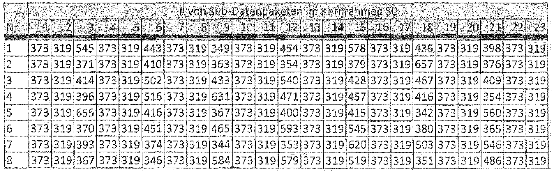
wobei das Frequenzsprungmuster eines aus den in der folgenden Tabelle genannten acht Frequenzsprungmustern mit jeweils 24 Sprüngen ist:

wherein the data transmitter (100) is configured to transmit data using a first hop pattern and a second hop pattern;
wherein the data is transmitted using the first hop pattern and wherein the data is repeatedly transmitted using the second hop pattern;
wherein the first hop pattern and the second hop pattern are each a time hop pattern, a frequency hop pattern, or a combination of the time hop pattern and the frequency hop pattern;
where the time jump pattern is one of the eight time jump patterns listed in the following table, each with 24 jumps:
where the frequency hopping pattern is one of the eight frequency hopping patterns listed in the following table, each with 24 hops:
wobei der Datenempfänger (110) ausgebildet ist, um Daten unter Verwendung eines ersten Sprungmusters und eines zweiten Sprungmusters zu empfangen;
wobei die Daten unter Verwendung des ersten Sprungmusters empfangen werden und wobei die Daten wiederholt unter Verwendung des zweiten Sprungmusters empfangen werden;
wobei das erste Sprungmuster und das zweite Sprungmuster jeweils ein Zeitsprungmuster, ein Frequenzsprungmuster oder eine Kombination aus dem Zeitsprungmuster und dem Frequenzsprungmuster ist;
wobei das Zeitsprungmuster eines aus den in der folgenden Tabelle genannten acht Zeitsprungmuster mit jeweils 24 Sprüngen ist:


wobei das Frequenzsprungmuster eines aus den in der folgenden Tabelle genannten acht Frequenzsprungmustern mit jeweils 24 Sprüngen ist:

wherein the data receiver (110) is configured to receive data using a first hop pattern and a second hop pattern;
wherein the data is received using the first jump pattern and wherein the data is received repeatedly using the second jump pattern;
wherein the first hop pattern and the second hop pattern are each a time hop pattern, a frequency hop pattern, or a combination of the time hop pattern and the frequency hop pattern;
where the time jump pattern is one of the eight time jump patterns listed in the following table, each with 24 jumps:
where the frequency hopping pattern is one of the eight frequency hopping patterns listed in the following table, each with 24 hops:
Applications Claiming Priority (3)
| Application Number | Priority Date | Filing Date | Title |
|---|---|---|---|
| DE102017211375.8A DE102017211375B3 (en) | 2017-07-04 | 2017-07-04 | Specific hopping patterns for repeatedly transmitting and receiving data and methods for generating the same |
| PCT/EP2018/067891 WO2019007933A1 (en) | 2017-07-04 | 2018-07-03 | Specific hopping pattern for repeatedly sending and receiving data and method for producing the same |
| EP18737241.2A EP3649758B1 (en) | 2017-07-04 | 2018-07-03 | Specific hopping pattern for repeatedly sending and receiving data |
Related Parent Applications (2)
| Application Number | Title | Priority Date | Filing Date |
|---|---|---|---|
| EP18737241.2A Division EP3649758B1 (en) | 2017-07-04 | 2018-07-03 | Specific hopping pattern for repeatedly sending and receiving data |
| EP18737241.2A Division-Into EP3649758B1 (en) | 2017-07-04 | 2018-07-03 | Specific hopping pattern for repeatedly sending and receiving data |
Publications (2)
| Publication Number | Publication Date |
|---|---|
| EP3846376A1 true EP3846376A1 (en) | 2021-07-07 |
| EP3846376B1 EP3846376B1 (en) | 2024-03-27 |
Family
ID=62816564
Family Applications (2)
| Application Number | Title | Priority Date | Filing Date |
|---|---|---|---|
| EP18737241.2A Active EP3649758B1 (en) | 2017-07-04 | 2018-07-03 | Specific hopping pattern for repeatedly sending and receiving data |
| EP21158768.8A Active EP3846376B1 (en) | 2017-07-04 | 2018-07-03 | Specific jump patterns for repeated transmission and reception of data |
Family Applications Before (1)
| Application Number | Title | Priority Date | Filing Date |
|---|---|---|---|
| EP18737241.2A Active EP3649758B1 (en) | 2017-07-04 | 2018-07-03 | Specific hopping pattern for repeatedly sending and receiving data |
Country Status (10)
| Country | Link |
|---|---|
| US (1) | US11258477B2 (en) |
| EP (2) | EP3649758B1 (en) |
| JP (1) | JP7043122B2 (en) |
| KR (1) | KR102385139B1 (en) |
| CN (1) | CN111034109B (en) |
| CA (1) | CA3068729A1 (en) |
| DE (1) | DE102017211375B3 (en) |
| MX (1) | MX2019015363A (en) |
| RU (1) | RU2742208C1 (en) |
| WO (1) | WO2019007933A1 (en) |
Families Citing this family (13)
| Publication number | Priority date | Publication date | Assignee | Title |
|---|---|---|---|---|
| DE102016010432B4 (en) * | 2016-08-27 | 2023-01-05 | Diehl Metering Systems Gmbh | Method for selecting the frequency channels of a communication system |
| DE102017206236A1 (en) * | 2017-04-11 | 2018-10-11 | Fraunhofer-Gesellschaft zur Förderung der angewandten Forschung e.V. | SPECIFIC HOPPING PATTERN FOR TELEGRAM SPLITTING |
| DE102017220061A1 (en) * | 2017-11-10 | 2019-05-16 | Fraunhofer-Gesellschaft zur Förderung der angewandten Forschung e.V. | Data transmitter and data receiver with low latency for the telegram splitting transmission method |
| RU2675256C1 (en) * | 2018-03-01 | 2018-12-18 | Общество с ограниченной ответственностью "РадиоТех" | Method of wireless communication between subscribers and basic stations |
| DE102018222859A1 (en) * | 2018-12-21 | 2020-06-25 | Fraunhofer-Gesellschaft zur Förderung der angewandten Forschung e.V. | Use of cyclically shifted basic patterns to optimize detection rates |
| EP3927047A4 (en) * | 2019-02-14 | 2022-11-30 | Ntt Docomo, Inc. | User terminal |
| WO2021029666A1 (en) * | 2019-08-12 | 2021-02-18 | 엘지전자 주식회사 | Technique for identifying transmission mode of ngv ppdu in wireless communication system |
| DE102019212704A1 (en) | 2019-08-23 | 2021-02-25 | Fraunhofer-Gesellschaft zur Förderung der angewandten Forschung e.V. | UNIPOLAR BINARY SEQUENCES WITH GOOD PERIODIC CORRELATION BEHAVIOR |
| DE102019213052A1 (en) | 2019-08-29 | 2021-03-04 | Fraunhofer-Gesellschaft zur Förderung der angewandten Forschung e.V. | Detection of signals from radio participants in a synchronized system |
| DE102019216347A1 (en) | 2019-10-23 | 2021-04-29 | Fraunhofer-Gesellschaft zur Förderung der angewandten Forschung e.V. | Unipolar binary sequences with improved non-periodic correlation behavior for unsynchronized TSMA systems |
| US11601177B2 (en) * | 2020-01-09 | 2023-03-07 | Qualcomm Incorporated | Channel state information (CSI) reporting for frequency hopping in unlicensed frequency bands |
| CN112671432B (en) * | 2020-12-29 | 2022-05-10 | 电子科技大学 | Frame design and timing synchronization method for short burst communication high-speed frequency hopping |
| CN117796089A (en) * | 2021-08-05 | 2024-03-29 | 华为技术有限公司 | Frequency hopping in NOMA |
Citations (4)
| Publication number | Priority date | Publication date | Assignee | Title |
|---|---|---|---|---|
| US20050176371A1 (en) | 2004-02-09 | 2005-08-11 | Arto Palin | Synchronization of time-frequency codes |
| DE102011082098B4 (en) | 2011-09-02 | 2014-04-10 | Fraunhofer-Gesellschaft zur Förderung der angewandten Forschung e.V. | Battery operated stationary sensor arrangement with unidirectional data transmission |
| WO2015128385A1 (en) | 2014-02-26 | 2015-09-03 | Fraunhofer-Gesellschaft zur Förderung der angewandten Forschung e.V. | Data transmission arrangement, data receiver, and method for the operation thereof |
| US20160044729A1 (en) | 2014-08-06 | 2016-02-11 | Interdigital Patent Holdings, Inc. | Methods and apparatus for determining device-to-device transmission patterns |
Family Cites Families (26)
| Publication number | Priority date | Publication date | Assignee | Title |
|---|---|---|---|---|
| US5907545A (en) * | 1996-01-16 | 1999-05-25 | Canon Kk | Wireless communication apparatus and method |
| US6212221B1 (en) | 1997-03-14 | 2001-04-03 | Brother Kogyo Kabushiki Kaisha | Communication apparatus |
| US6549784B1 (en) * | 1998-12-28 | 2003-04-15 | At&T Corp. | Method and apparatus for implementing measurement based dynamic frequency hopping in wireless communication systems |
| US6970495B1 (en) * | 2000-02-09 | 2005-11-29 | Texas Instruments Incorporated | Adjustment of slave frequency hopping pattern to improve channel measurement opportunities in wireless communications |
| DE10211235B4 (en) * | 2002-03-13 | 2010-11-11 | Abb Research Ltd. | Method for generating a frequency hopping frequency sequence |
| CN103297204B (en) * | 2004-04-02 | 2017-03-01 | 苹果公司 | Space Time Transmit Diversity system and method for OFDM application |
| WO2008013339A1 (en) * | 2006-07-26 | 2008-01-31 | Electronics And Telecommunications Research Institute | Cell search method in ofdm cellular system, frame transmission method thereof, and forward link frame structure thereof |
| EP2015465A3 (en) * | 2007-07-11 | 2014-07-09 | Abb Ag | Method for producing frequency hopping sequences |
| US8140102B2 (en) | 2007-08-14 | 2012-03-20 | Motorola Mobility, Inc. | Method and apparatus for transmit power calibration in a frequency division multiplexed wireless system |
| US7876843B2 (en) * | 2007-09-27 | 2011-01-25 | Infineon Technologies Ag | Method for data transmission and communication system |
| JP4661887B2 (en) * | 2008-03-05 | 2011-03-30 | ソニー株式会社 | Wireless communication apparatus, wireless communication system, wireless communication method, and program |
| US8121097B2 (en) * | 2008-11-04 | 2012-02-21 | Qualcomm Incorporated | Transmission with hopping for peer-peer communication |
| CN102365827A (en) * | 2009-02-02 | 2012-02-29 | 株式会社Ntt都科摩 | Base station apparatus and method in mobile communication system |
| PT2496005T (en) * | 2009-10-30 | 2018-10-19 | Sun Patent Trust | Wireless communication apparatus and reference signal generating method |
| US9276710B2 (en) * | 2009-12-21 | 2016-03-01 | Qualcomm Incorporated | Method and apparatus for resource allocation with carrier extension |
| MX2013003420A (en) * | 2010-10-01 | 2013-05-20 | Research In Motion Ltd | Frequency-hopping method for lte aperiodic sounding reference signals. |
| KR102128076B1 (en) * | 2013-12-20 | 2020-06-30 | 삼성전자주식회사 | Method of transmitting a signal, and device operating the same |
| WO2015182949A1 (en) * | 2014-05-27 | 2015-12-03 | 엘지전자 주식회사 | Data transmission method and apparatus by device to device terminal in wireless communication system |
| JP6731002B2 (en) * | 2015-06-03 | 2020-07-29 | 華為技術有限公司Huawei Technologies Co.,Ltd. | Frequency domain resource configuration method and apparatus |
| US10305646B2 (en) * | 2016-01-22 | 2019-05-28 | Space Systems/Loral LLC | Protected overlay of assigned frequency channels |
| JP6788732B2 (en) * | 2016-08-08 | 2020-11-25 | 華為技術有限公司Huawei Technologies Co.,Ltd. | Device-to-device communication method and terminal device |
| DE102016220882A1 (en) | 2016-10-24 | 2018-04-26 | Fraunhofer-Gesellschaft zur Förderung der angewandten Forschung e.V. | Optimized hopping patterns for different sensor nodes and variable data lengths based on the telegram splitting transmission method |
| DE102016220883A1 (en) | 2016-10-24 | 2018-04-26 | Fraunhofer-Gesellschaft zur Förderung der angewandten Forschung e.V. | Optimized combination of preamble and data fields for sensor networks with low power consumption based on the telegram splitting method |
| US11323966B2 (en) * | 2016-10-28 | 2022-05-03 | Qualcomm Incorporated | Uplink transmission techniques in low latency wireless communication systems |
| US10284343B2 (en) * | 2016-11-04 | 2019-05-07 | Qualcomm Incorporated | Frequency hopping for multicast service transmissions for narrowband devices |
| DE102017206236A1 (en) | 2017-04-11 | 2018-10-11 | Fraunhofer-Gesellschaft zur Förderung der angewandten Forschung e.V. | SPECIFIC HOPPING PATTERN FOR TELEGRAM SPLITTING |
-
2017
- 2017-07-04 DE DE102017211375.8A patent/DE102017211375B3/en active Active
-
2018
- 2018-07-03 EP EP18737241.2A patent/EP3649758B1/en active Active
- 2018-07-03 CN CN201880054147.5A patent/CN111034109B/en active Active
- 2018-07-03 EP EP21158768.8A patent/EP3846376B1/en active Active
- 2018-07-03 KR KR1020207003303A patent/KR102385139B1/en active IP Right Grant
- 2018-07-03 WO PCT/EP2018/067891 patent/WO2019007933A1/en active Search and Examination
- 2018-07-03 MX MX2019015363A patent/MX2019015363A/en unknown
- 2018-07-03 RU RU2020104699A patent/RU2742208C1/en active
- 2018-07-03 JP JP2019572512A patent/JP7043122B2/en active Active
- 2018-07-03 CA CA3068729A patent/CA3068729A1/en active Granted
-
2019
- 2019-12-18 US US16/719,906 patent/US11258477B2/en active Active
Patent Citations (4)
| Publication number | Priority date | Publication date | Assignee | Title |
|---|---|---|---|---|
| US20050176371A1 (en) | 2004-02-09 | 2005-08-11 | Arto Palin | Synchronization of time-frequency codes |
| DE102011082098B4 (en) | 2011-09-02 | 2014-04-10 | Fraunhofer-Gesellschaft zur Förderung der angewandten Forschung e.V. | Battery operated stationary sensor arrangement with unidirectional data transmission |
| WO2015128385A1 (en) | 2014-02-26 | 2015-09-03 | Fraunhofer-Gesellschaft zur Förderung der angewandten Forschung e.V. | Data transmission arrangement, data receiver, and method for the operation thereof |
| US20160044729A1 (en) | 2014-08-06 | 2016-02-11 | Interdigital Patent Holdings, Inc. | Methods and apparatus for determining device-to-device transmission patterns |
Non-Patent Citations (4)
| Title |
|---|
| ALEX E LAM ET AL., TIME-HOPPING AND FREQUENCY-HOPPING MULTIPLE-ACCESS PACKET COMMUNICATIONS |
| ALEX W LAM ET AL: "Time-Hopping and Frequency-Hopping Multiple-Access Packet Communications", IEEE TRANSACTIONS ON COMMUNICATIONS, IEEE SERVICE CENTER, PISCATAWAY, NJ. USA, vol. 38, no. 6, 1 June 1990 (1990-06-01), pages 875 - 888, XP002671768, ISSN: 0090-6778, DOI: 10.1109/26.57480 * |
| G. KILIANH. PETKOVR. PSIUKH. LIESKEF. BEERJ. ROBERTA. HEUBERGER: "Improved coverage for low-power telemetry systems using telegram splitting", PROCEEDINGS OF 2013 EUROPEAN CONFERENCE ON SMART OBJECTS, SYSTEMS AND TECHNOLOGIES (SMARTSYSTECH, 2013 |
| G. KILIANM. BREILINGH. H. PETKOVH. LIESKEF. BEERJ. ROBERTA. HEUBERGER: "Increasing Transmission Reliability for Telemetry Systems Using Telegram Splitting", IEEE TRANSACTIONS ON COMMUNICATIONS, vol. 63, no. 3, March 2015 (2015-03-01), pages 949 - 961 |
Also Published As
| Publication number | Publication date |
|---|---|
| RU2742208C1 (en) | 2021-02-03 |
| US11258477B2 (en) | 2022-02-22 |
| CN111034109B (en) | 2022-10-04 |
| EP3649758A1 (en) | 2020-05-13 |
| CA3068729A1 (en) | 2019-01-10 |
| EP3846376B1 (en) | 2024-03-27 |
| US20200177233A1 (en) | 2020-06-04 |
| CN111034109A (en) | 2020-04-17 |
| WO2019007933A9 (en) | 2020-02-06 |
| KR102385139B1 (en) | 2022-04-12 |
| JP2020526129A (en) | 2020-08-27 |
| MX2019015363A (en) | 2021-11-18 |
| EP3649758B1 (en) | 2021-09-01 |
| WO2019007933A1 (en) | 2019-01-10 |
| JP7043122B2 (en) | 2022-03-29 |
| KR20200019251A (en) | 2020-02-21 |
| DE102017211375B3 (en) | 2018-12-13 |
Similar Documents
| Publication | Publication Date | Title |
|---|---|---|
| EP3649758B1 (en) | Specific hopping pattern for repeatedly sending and receiving data | |
| EP3610575A2 (en) | Specific hopping patterns for telegram splitting | |
| EP3529938B1 (en) | Optimized hopping pattern for different sensornodes and variable datalength based on the telegram splitting transmission system | |
| EP3707839A1 (en) | Data transmitter and data receiver having low latency for the telegram-splitting transmission method | |
| WO2018077814A1 (en) | Optimized combination of preamble and data fields for sensor networks with low power consumption on the basis of the telegram splitting method | |
| EP3610574B1 (en) | Transmitter and receiver and corresponding methods | |
| EP3694126B1 (en) | Telegram division transfer method for bi-directional networks | |
| WO2021078816A2 (en) | Unipolar binary sequences having improved non-periodic correlation behaviour for unsynchronised tsma systems | |
| WO2020048877A1 (en) | Synchronization beacon | |
| EP3900247B1 (en) | Use of cyclically shifted basic patterns for detection rate optimization | |
| EP3782292B1 (en) | Packet correlator for a wireless transmission system | |
| WO2021037849A1 (en) | Detection of signals of radio subscribers in a synchronized system | |
| WO2020173976A2 (en) | Method for coordinating subscribers in sensor networks | |
| DE102018220766B4 (en) | SIMPLIFIED COMBINATION OF CODED DATA PACKAGES | |
| EP3874703A2 (en) | Detection of a pilot sequence on simple receivers | |
| WO2020048869A1 (en) | Circular hopping pattern | |
| DE102016202875B4 (en) | Method for transmitting data | |
| DE102011015095A1 (en) | Method for communication in wireless ad-hoc-network i.e. military and civilian communication and sensor network, in production hall, involves forming associations or frequency hopping sequence, and separating planes by scrambling process |
Legal Events
| Date | Code | Title | Description |
|---|---|---|---|
| PUAI | Public reference made under article 153(3) epc to a published international application that has entered the european phase |
Free format text: ORIGINAL CODE: 0009012 |
|
| STAA | Information on the status of an ep patent application or granted ep patent |
Free format text: STATUS: THE APPLICATION HAS BEEN PUBLISHED |
|
| AC | Divisional application: reference to earlier application |
Ref document number: 3649758 Country of ref document: EP Kind code of ref document: P |
|
| AK | Designated contracting states |
Kind code of ref document: A1 Designated state(s): AL AT BE BG CH CY CZ DE DK EE ES FI FR GB GR HR HU IE IS IT LI LT LU LV MC MK MT NL NO PL PT RO RS SE SI SK SM TR |
|
| STAA | Information on the status of an ep patent application or granted ep patent |
Free format text: STATUS: REQUEST FOR EXAMINATION WAS MADE |
|
| 17P | Request for examination filed |
Effective date: 20220225 |
|
| RBV | Designated contracting states (corrected) |
Designated state(s): AL AT BE BG CH CY CZ DE DK EE ES FI FR GB GR HR HU IE IS IT LI LT LU LV MC MK MT NL NO PL PT RO RS SE SI SK SM TR |
|
| REG | Reference to a national code |
Ref country code: HK Ref legal event code: DE Ref document number: 40056742 Country of ref document: HK |
|
| RAP3 | Party data changed (applicant data changed or rights of an application transferred) |
Owner name: FRAUNHOFER-GESELLSCHAFT ZUR FOERDERUNG DER ANGEWANDTEN FORSCHUNG E.V. |
|
| GRAP | Despatch of communication of intention to grant a patent |
Free format text: ORIGINAL CODE: EPIDOSNIGR1 |
|
| STAA | Information on the status of an ep patent application or granted ep patent |
Free format text: STATUS: GRANT OF PATENT IS INTENDED |
|
| RIC1 | Information provided on ipc code assigned before grant |
Ipc: H04L 5/00 20060101AFI20230920BHEP |
|
| INTG | Intention to grant announced |
Effective date: 20231013 |
|
| GRAS | Grant fee paid |
Free format text: ORIGINAL CODE: EPIDOSNIGR3 |
|
| GRAA | (expected) grant |
Free format text: ORIGINAL CODE: 0009210 |
|
| STAA | Information on the status of an ep patent application or granted ep patent |
Free format text: STATUS: THE PATENT HAS BEEN GRANTED |
|
| AC | Divisional application: reference to earlier application |
Ref document number: 3649758 Country of ref document: EP Kind code of ref document: P |
|
| AK | Designated contracting states |
Kind code of ref document: B1 Designated state(s): AL AT BE BG CH CY CZ DE DK EE ES FI FR GB GR HR HU IE IS IT LI LT LU LV MC MK MT NL NO PL PT RO RS SE SI SK SM TR |
|
| REG | Reference to a national code |
Ref country code: GB Ref legal event code: FG4D Free format text: NOT ENGLISH |
|
| REG | Reference to a national code |
Ref country code: CH Ref legal event code: EP |
|
| REG | Reference to a national code |
Ref country code: DE Ref legal event code: R096 Ref document number: 502018014347 Country of ref document: DE |