EP3846359B1 - Procédés et dispositifs de géolocalisation d'un premier terminal de télécommunication satellite, programmes d'ordinateur associés - Google Patents
Procédés et dispositifs de géolocalisation d'un premier terminal de télécommunication satellite, programmes d'ordinateur associés Download PDFInfo
- Publication number
- EP3846359B1 EP3846359B1 EP20217976.8A EP20217976A EP3846359B1 EP 3846359 B1 EP3846359 B1 EP 3846359B1 EP 20217976 A EP20217976 A EP 20217976A EP 3846359 B1 EP3846359 B1 EP 3846359B1
- Authority
- EP
- European Patent Office
- Prior art keywords
- terminal
- time
- sat
- geolocation
- satellite
- Prior art date
- Legal status (The legal status is an assumption and is not a legal conclusion. Google has not performed a legal analysis and makes no representation as to the accuracy of the status listed.)
- Active
Links
Images



Classifications
-
- G—PHYSICS
- G01—MEASURING; TESTING
- G01S—RADIO DIRECTION-FINDING; RADIO NAVIGATION; DETERMINING DISTANCE OR VELOCITY BY USE OF RADIO WAVES; LOCATING OR PRESENCE-DETECTING BY USE OF THE REFLECTION OR RERADIATION OF RADIO WAVES; ANALOGOUS ARRANGEMENTS USING OTHER WAVES
- G01S5/00—Position-fixing by co-ordinating two or more direction or position line determinations; Position-fixing by co-ordinating two or more distance determinations
- G01S5/02—Position-fixing by co-ordinating two or more direction or position line determinations; Position-fixing by co-ordinating two or more distance determinations using radio waves
- G01S5/0246—Position-fixing by co-ordinating two or more direction or position line determinations; Position-fixing by co-ordinating two or more distance determinations using radio waves involving frequency difference of arrival or Doppler measurements
-
- G—PHYSICS
- G01—MEASURING; TESTING
- G01S—RADIO DIRECTION-FINDING; RADIO NAVIGATION; DETERMINING DISTANCE OR VELOCITY BY USE OF RADIO WAVES; LOCATING OR PRESENCE-DETECTING BY USE OF THE REFLECTION OR RERADIATION OF RADIO WAVES; ANALOGOUS ARRANGEMENTS USING OTHER WAVES
- G01S5/00—Position-fixing by co-ordinating two or more direction or position line determinations; Position-fixing by co-ordinating two or more distance determinations
- G01S5/02—Position-fixing by co-ordinating two or more direction or position line determinations; Position-fixing by co-ordinating two or more distance determinations using radio waves
- G01S5/0205—Details
- G01S5/0226—Transmitters
- G01S5/0231—Emergency, distress or locator beacons
-
- G—PHYSICS
- G01—MEASURING; TESTING
- G01S—RADIO DIRECTION-FINDING; RADIO NAVIGATION; DETERMINING DISTANCE OR VELOCITY BY USE OF RADIO WAVES; LOCATING OR PRESENCE-DETECTING BY USE OF THE REFLECTION OR RERADIATION OF RADIO WAVES; ANALOGOUS ARRANGEMENTS USING OTHER WAVES
- G01S5/00—Position-fixing by co-ordinating two or more direction or position line determinations; Position-fixing by co-ordinating two or more distance determinations
- G01S5/02—Position-fixing by co-ordinating two or more direction or position line determinations; Position-fixing by co-ordinating two or more distance determinations using radio waves
- G01S5/0249—Determining position using measurements made by a non-stationary device other than the device whose position is being determined
-
- G—PHYSICS
- G01—MEASURING; TESTING
- G01S—RADIO DIRECTION-FINDING; RADIO NAVIGATION; DETERMINING DISTANCE OR VELOCITY BY USE OF RADIO WAVES; LOCATING OR PRESENCE-DETECTING BY USE OF THE REFLECTION OR RERADIATION OF RADIO WAVES; ANALOGOUS ARRANGEMENTS USING OTHER WAVES
- G01S5/00—Position-fixing by co-ordinating two or more direction or position line determinations; Position-fixing by co-ordinating two or more distance determinations
- G01S5/02—Position-fixing by co-ordinating two or more direction or position line determinations; Position-fixing by co-ordinating two or more distance determinations using radio waves
- G01S5/14—Determining absolute distances from a plurality of spaced points of known location
Definitions
- the present invention relates to the field of geolocation of a satellite telecommunications terminal using a transparent moving satellite.
- a “moving satellite” is a non-geostationary satellite, i.e. one whose circular orbit is distinct from 35,786 km: for example, a satellite in a moving constellation of the LEO (Low Earth Orbit), MEO (Medium Earth Orbit) or HEO (Highly Elliptical Orbit) type.
- a “transparent satellite” is a satellite whose signal processing is limited to amplification and frequency conversion between the uplinks and downlinks. The value of this frequency conversion is known.
- the present invention relates to a method for geolocating a first satellite telecommunications terminal based on signals exchanged by said first telecommunications terminal, on a satellite telecommunications link via a transparent moving satellite, with a second satellite telecommunications terminal whose location is known.
- the invention proposes a geolocation method according to claim 1.
- the present invention allowing the geolocation of the first terminal by the second terminal does not require an explicit exchange of position, it allows to locate a terminal passively, without explicit message, without creating a change in the waveform; furthermore, it requires only a single antenna.
- the present invention exploits the temporal evolutions of one or more radiofrequency parameters of the link generated by the transparent scrolling constellations dependent on the position of the first terminal.
- the invention proposes a geolocation method according to claim 2.
- the present invention provides a computer program according to claim 6.
- the present invention provides a geolocation device according to claim 7.
- the present invention provides a geolocation device according to claim 8.
- a geolocation device is according to claim 9.
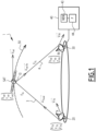
- FIG. 1 represents a system 1 for satellite telecommunications moving in one embodiment of the invention, comprising a satellite moving 10 and two terminals 20, 30 for telecommunications by this satellite.
- Each of these terminals is equipped with the technical means for implementing such satellite telecommunications (for example a radiosatellite antenna, an amplification and frequency change block and a modem); these means are known and are not detailed here.
- Satellite 10 is of the transparent type.
- the terminal 30, called the Rx terminal 30, is provided with a geolocation device 40 adapted to analyze the signals received by the terminal 30 from the terminal 20, called the Tx terminal 20, and to determine a geolocation of the Tx terminal 20 in a first embodiment, based on this analysis.
- the signals are transmitted by the Tx terminal 20 on the uplink 3 to the satellite 10, then transmitted on the downlink 4 to the Rx terminal 30.
- the terminal 30 in this first embodiment is an anchor station, in relation with several user terminals. It knows its position and that of the satellite (it must point towards it).
- the geolocation device 40 comprises a memory 43 and a processor 44.
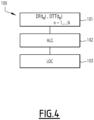
- the memory 43 comprises software instructions, which when executed on the processor 44, automatically implement the steps incumbent on the geolocation device 40 described with reference to the figure 4 .
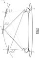
- satellite 10 creates temporal variations in Doppler shift and transit time, as shown in figure 2 considering the position of the satellite at three successive instants t0, t1, t2, as well as the corresponding values of Doppler shift ⁇ F(t0), ⁇ F(t1), ⁇ F(t2) and transit time TT(t0), TT(t1), TT(t2).
- Doppler shift is the frequency shift of a wave observed when the distance between the transmitter and the receiver varies over time and transit time is the propagation time of the wave on the uplink 3 and on the downlink 4.
- the Doppler evolution and the transit time evolution depend on the position of the Tx terminal 20 to be located, the known position of the Rx terminal 30, the known position of the satellite 10, the known frequency f UL of the uplink 3 and the known frequency f DL of the downlink 4.
- the orthonormal frame can be fixed or inertial relative to the earth.
- V mouvX which, in practice, is weak in front of V land in the case of scrolling constellations, is neglected here: at the equator, the component of the velocity vector due to the rotation of the earth is 465 m/s, or 1675 km/h. Moreover, the estimate is fast enough to neglect this term.
- the velocity vector of the Tx 20 terminal can be compared to that of the rotation of the Earth. Note that we could also consider that the velocity vector of a terminal is equal to the sum of this rotation vector and a determined velocity, for example a constant vector, representing the displacement of the terminal relative to the Earth. Even more generally, we could also find the complete velocity vector by integrating it into formula 1.
- One method for estimating it is, for example, to renew the position estimate regularly. Since the estimation method is fast, it can neglect the carrier velocity term. By renewing the measurement after a period where the velocity vector has significantly varied the position, a measurement is made again. The velocity vector is given by the position variation during this period. A solution using a Kalman filter will give a more precise estimate.
- the orthonormal frame can be fixed or inertial relative to the Earth.
- the set 100 of steps is implemented by the geolocation device 40.
- the delay between successive measurement moments is for example in the range 0.1 ms to 10 s.
- a step 102 in an unclaimed manner the system of equations defined by the N F equalities between each successive value ⁇ F(t) calculated at each of the successive instants t and by the corresponding formula (1) considered at said instant t is resolved by the implementation of an algorithm for solving the system of equations by the geolocation device 40; and/or the system of equations defined by the N T equalities between each successive value TT(t) calculated at each of the successive instants t and by the corresponding formula (2) considered at said instant t is resolved by the implementation of an algorithm for solving the system of equations by the geolocation device 40.
- the geolocation of terminal Tx 20 at time t is equal to that from which the vector uTxSat ( t ) defined by said equation system points to the satellite
- a step 103 the determination of the geolocation of the terminal Tx 20 is completed, by selecting the one of the two symmetrical positions which can be retained and by combining, where appropriate, the distinct geolocations determined via the transit time and the Doppler shift.
- the line ⁇ F1(t) represents the sequence of the ⁇ F values calculated by the terminal RX1 following the analysis of the signal received terminal TX1 20_1, corresponding to the anchor station 30 mentioned above.
- ⁇ F2(t), respectively ⁇ F3(t) correspond to the signals received from TX2 20_2, respectively TX3 20_3 in their respective position.
- the curve TT1(t), respectively TT2(t), TT3(t) represents the sequence of TT values calculated by the terminal RX1, corresponding to the anchor station 30 mentioned above, for the terminal TX1 20_1, respectively TX2 20_2, TX3 20_3 in their respective position.
- the present invention thus makes it possible to determine the geolocation of a satellite terminal in the network using signals exchanged, on the downlink, with this terminal, without requiring GNSS.
- a separate processing relating to the evolution of the Doppler observations ⁇ F and/or the observations TT(t) of the transit time completes, or replaces, the direct resolution processing of the system of equations presented, described above.
- the geolocation device 40 obtains the N F successive observations relating to the Doppler and/or the N T successive observations relating to the transit time of step 101, which defines a profile calculated in accordance with step 101.
- the geolocation device 40 compares the Doppler shift profile thus calculated from the observation to the Doppler shift time profiles previously associated with the grid points and selects the closest profile: the geolocation device 40 then assigns to the terminal to be geolocated the position of the grid point associated with the selected profile.
- the predefined theoretical profiles ⁇ F in the preliminary phase and associated with the grid points P1, P2, P3 are represented in solid lines for P1, in dotted lines for P2 and in crosses for P3 and numbered respectively 1, 2, 3 while the profile calculated from the observation of the signals received, named Obs, according to the measurements of step 101, is represented in bold.
- the terminal to be located is in PR; the grid point P2 is that of the three grid points considered here whose associated predefined profile is closest to the observation profile.
- the geolocation device 40 compares the calculated transit time profile with the theoretical transit time profiles associated with the grid points and selects the closest theoretical profile: the geolocation device 40 then assigns to the terminal to be geolocated the position of the grid point associated with the selected profile.
- a unique solution is determined by applying a predefined rule (e.g. averaging).
- the profile comparison step is repeated only in a reduced sub-area of coverage around the geolocation point, considering a finer mesh (for example 1°, then 0.1°, then 0.01° ...), to refine the geolocation while limiting the calculations.
- a finer mesh for example 1°, then 0.1°, then 0.01°
- a separate processing relating to the evolution of the Doppler observations ⁇ F and/or the observations TT(t) of the transit time completes, or replaces, the direct resolution processing of the system of equations presented, described above and/or the processing according to the MDR1 embodiment described above.
- the evolution of the function ⁇ F and/or TT is modeled in the form of polynomials: first order for the Doppler shift and second order for the transit time.
- the values of the coefficients depend in particular on the position of the terminal to be determined.
- the method is illustrated in figure 6 (with a fixed step).
- the first position of the transmitter terminal Tx 20 is taken as corresponding to the location identified by the point Hyp1 on a geographic map; it is determined that: a hyp , 1 ⁇ a obs > 0 ; b hyp , 1 ⁇ b obs > 0 ; and a likelihood criterion value equal to ⁇ hyp , 1.
- the second position considered becomes that indicated by the point Hyp2 for the second iteration. For this position, it is then determined that: a hyp , 2 ⁇ a obs > 0 b hyp , 2 ⁇ b obs > 0 and a likelihood criterion value equal to e hyp, 2 ⁇ ⁇ hyp , 1.
- the third position considered becomes that indicated by point Hyp3 for the third iteration. For this position, it is then determined that: a hyp , 3 ⁇ a obs > 0 b hyp , 3 ⁇ b obs ⁇ 0 and a likelihood criterion value equal to ⁇ hyp, 3 ⁇ ⁇ hyp, 2 .
- the fourth position considered becomes that indicated by point Hyp4 for the fourth iteration. For this position, it is then determined that: a hyp , 4 ⁇ a obs ⁇ 0 b hyp , 4 ⁇ b obs > 0 and a likelihood criterion value equal to ⁇ hyp, 4 > ⁇ hyp, 3 .
- the geolocation device 40 in the Rx terminal 30 determined the position of the Tx terminal 20 on the basis of the signals received by the Rx terminal 30 on the downlink 4 from the Tx terminal 20.
- the geolocation device 40 in the Rx terminal 30 is adapted to determine its own position on the basis of the signals received by the Rx terminal 30 on the downlink 4 from the Tx terminal 20 (which is for example this time the anchor station): then the terminal Rx 30 knows the position of the terminal Tx 20 and that of the satellite; this time, the unknown in formula 1 is u SatRx ( t ) .
- the unknowns are this time ( X Rx ; Y Rx ; Z Rx ), coordinates of terminal Rx 30.
- the geolocation device 40 can be remote from the Rx terminal 30, while operating on the signals received by the latter.
- the geolocation device 40 is produced in the form of a programmable logic component, such as an FPGA ( Field Programmable Gate Array), or in the form of a dedicated integrated circuit, such as an ASIC ( Applications Specific Integrated Circuit ) or a DSP (Digital Signal Processor) or GPU (Graphies Processing Unit).
- a programmable logic component such as an FPGA ( Field Programmable Gate Array)
- ASIC Applications Specific Integrated Circuit
- DSP Digital Signal Processor
- GPU Graphics Processing Unit
- the orthonormal frame can be fixed or inertial relative to the earth.
- V land is the velocity vector of the Rx 30 terminal to the rotation of the earth.
- V movex is the velocity vector due to the movement of the Rx 30 terminal on the earth.
- V mouvX which, in practice, is weak in front of V land in the case of scrolling constellations, is neglected here: at the equator, the component of the velocity vector due to the rotation of the earth is 465 m/s, or 1675 km/h. Moreover, the estimate is fast enough to neglect this term.
- the velocity vector of the Tx 20 terminal can be assimilated to that of the rotation of the earth.
- the velocity vector of a terminal is equal to the sum of this rotation vector and a velocity determined, for example a constant vector, representing the displacement of the terminal relative to the earth
- a velocity determined for example a constant vector, representing the displacement of the terminal relative to the earth
- One method to estimate it is, for example, to renew the position estimate regularly. Since the estimation method is fast, it can neglect the carrier velocity term. By renewing the measurement after a period where the velocity vector has significantly varied the position, a new measurement is made. The velocity vector is given by the position variation during this period. A solution using a Kalman filter will give a more precise estimate.
- the orthonormal frame can be fixed or inertial relative to the Earth.
- the set 100 of steps is implemented by the geolocation device 40.
- the delay between successive measurement moments is for example in the range 0.1 ms to 10 s.
- a step 102 the system of equations defined by the N F equalities between each successive value ⁇ F(t) calculated at each of the successive instants t and by the corresponding formula (1) considered at said instant t is resolved by the implementation of an algorithm for solving the system of equations by the geolocation device 40; and/or the system of equations defined by the N T equalities between each successive value TT(t) calculated at each of the successive instants t and by the corresponding formula (2) considered at said instant t is resolved by the implementation of an algorithm for solving the system of equations by the geolocation device 40.
- the geolocation of terminal Tx 20 at time t is equal to that from which the vector u TxSat ( t ) defined by said equation system points to the satellite
- a step 103 the determination of the geolocation of the terminal Tx 20 is completed, by selecting the one of the two symmetrical positions which can be retained and by combining, where appropriate, the distinct geolocations determined via the transit time and the Doppler shift.
- the line ⁇ F1(t) represents the sequence of ⁇ F values calculated by the terminal RX1 following the analysis of the received signal terminal TX1 20_1, corresponding to the anchor station 30 mentioned above.
- ⁇ F2(t), respectively ⁇ F3(t) correspond to the signals received from the TX2 20_2, respectively TX3 20_3 in their respective position.
- the curve TT1(t), respectively TT2(t), TT3(t) represents the sequence of the TT values calculated by the terminal RX1, corresponding to the anchor station 30 mentioned above, for the terminal TX1 20_1, respectively TX2 20_2, TX3 20_3 in their respective position.
- the present invention thus makes it possible to determine the geolocation of a satellite terminal in the network using signals exchanged, on the downlink, with this terminal, without requiring GNSS.
- a separate processing relating to the evolution of the Doppler observations ⁇ F and/or the observations TT(t) of the transit time completes, or replaces, the direct resolution processing of the system of equations presented, described above.
- the geolocation device 40 obtains the N F successive observations relating to the Doppler and/or the N T successive observations relating to the transit time of step 101, which defines a profile calculated in accordance with step 101.
- the geolocation device 40 compares the Doppler shift profile thus calculated from the observation with the Doppler shift time profiles previously associated with the grid points and selects the closest profile: the geolocation device 40 then assigns to the terminal to be geolocated the position of the grid point associated with the selected profile.
- the predefined theoretical profiles ⁇ F in the preliminary phase and associated with the grid points P1, P2, P3 are represented in solid lines for P1, in dotted lines for P2 and in crosses for P3 and numbered respectively 1, 2, 3 while the profile calculated from the observation of the received signals, named Obs, based on the measurements of step 101, is shown in bold.
- the terminal to be located is in PR; point P2 of the grid is that of the three points of the grid considered here whose associated predefined profile is closest to the observation profile.
- the geolocation device 40 compares the calculated transit time profile with the theoretical transit time profiles associated with the grid points and selects the closest theoretical profile: the geolocation device 40 then assigns to the terminal to be geolocated the position of the grid point associated with the selected profile.
- a unique solution is determined by applying a predefined rule (e.g. averaging).
- the profile comparison step is repeated only in a reduced sub-area of coverage around the geolocation point, considering a finer mesh (for example 1°, then 0.1°, then 0.01° ...), to refine the geolocation while limiting the calculations.
- a finer mesh for example 1°, then 0.1°, then 0.01°
- a separate processing relating to the evolution of the Doppler observations ⁇ F and/or the observations TT(t) of the transit time completes, or replaces, the direct resolution processing of the system of equations presented, described above and/or the processing according to the embodiment MDR1 described above.
- the evolution of the function ⁇ F and/or TT is modeled in the form of polynomials: first order for the Doppler shift and second order for the transit time.
- the values of the coefficients depend in particular on the position of the terminal to be determined.
- the method is illustrated in figure 6 (with a fixed step).
- the first position of the transmitter terminal Tx 20 is taken as corresponding to the location identified by the point Hyp1 on a geographic map; it is determined that: a hyp , 1 ⁇ a obs > 0 ; b hyp , 1 ⁇ b obs > 0 ; and a likelihood criterion value equal to ⁇ hyp ,1 .
- the second position considered becomes that indicated by the point Hyp2 for the second iteration. For this position, it is then determined that: a hyp , 2 ⁇ a obs > 0 b hyp , 2 ⁇ b obs > 0 and a likelihood criterion value equal to ⁇ hyp, 2 ⁇ ⁇ hyp , 1 .
- the third position considered becomes that indicated by point Hyp3 for the third iteration. For this position, it is then determined that: a hyp , 3 ⁇ a obs > 0 b hyp , 3 ⁇ b obs ⁇ 0 and a likelihood criterion value equal to ⁇ hyp ,3 ⁇ ⁇ hyp, 2 .
- the fourth position considered becomes that indicated by point Hyp4 for the fourth iteration. For this position, it is then determined that: a hyp , 4 ⁇ a obs ⁇ 0 b hyp , 4 ⁇ b obs > 0 and a likelihood criterion value equal to ⁇ hyp ,4 > ⁇ hyp ,3 .
- the geolocation device 40 in the Rx terminal 30 determined the position of the Tx terminal 20 based on the signals received by the Rx terminal 30 on the downlink 4 from the Tx terminal 20.
- the geolocation device 40 in the Rx terminal 30 is adapted to determine its own position based on the signals received by the Rx terminal 30 on the downlink 4 from the Tx terminal 20 (which is for example this time the anchor station): then the Rx terminal 30 knows the position of the Tx terminal 20 and that of the satellite; this time, the unknown in formula 1 is u SatRx ( t ) .
- the unknowns are this time ( X Rx ; Y Rx ; Z Rx ) , coordinates of terminal Rx 30.
- the geolocation device 40 can be remote from the Rx terminal 30, while operating on the signals received by the latter.
- the geolocation device 40 is produced in the form of a programmable logic component, such as an FPGA ( Field Programmable Gate Array ), or in the form of a dedicated integrated circuit, such as an ASIC ( Applications Specific Integrated Circuit ) or a DSP (Digital Signal Processor) or GPU (Graphies Processing Unit).
- a programmable logic component such as an FPGA ( Field Programmable Gate Array )
- ASIC Applications Specific Integrated Circuit
- DSP Digital Signal Processor
- GPU Graphics Processing Unit
Landscapes
- Physics & Mathematics (AREA)
- Engineering & Computer Science (AREA)
- General Physics & Mathematics (AREA)
- Radar, Positioning & Navigation (AREA)
- Remote Sensing (AREA)
- Radio Relay Systems (AREA)
- Position Fixing By Use Of Radio Waves (AREA)
Applications Claiming Priority (1)
| Application Number | Priority Date | Filing Date | Title |
|---|---|---|---|
| FR1915767A FR3105837B1 (fr) | 2019-12-31 | 2019-12-31 | Procedes et dispositifs de geolocalisation d'un premier terminal de telecommunication satellite, programmes d'ordinateur associes |
Publications (2)
| Publication Number | Publication Date |
|---|---|
| EP3846359A1 EP3846359A1 (fr) | 2021-07-07 |
| EP3846359B1 true EP3846359B1 (fr) | 2025-01-15 |
Family
ID=72560638
Family Applications (1)
| Application Number | Title | Priority Date | Filing Date |
|---|---|---|---|
| EP20217976.8A Active EP3846359B1 (fr) | 2019-12-31 | 2020-12-31 | Procédés et dispositifs de géolocalisation d'un premier terminal de télécommunication satellite, programmes d'ordinateur associés |
Country Status (4)
| Country | Link |
|---|---|
| EP (1) | EP3846359B1 (pl) |
| ES (1) | ES3021875T3 (pl) |
| FR (1) | FR3105837B1 (pl) |
| PL (1) | PL3846359T3 (pl) |
Families Citing this family (1)
| Publication number | Priority date | Publication date | Assignee | Title |
|---|---|---|---|---|
| EP4657108A1 (en) * | 2024-05-28 | 2025-12-03 | Eutelsat SA | Method for locating a ground-based device using one leo satellite and associated system |
Family Cites Families (4)
| Publication number | Priority date | Publication date | Assignee | Title |
|---|---|---|---|---|
| US6028551A (en) * | 1994-12-13 | 2000-02-22 | Schoen; Neil Charles | Micro-miniature beacon transmit-only geo-location emergency system for personal security |
| EP2784534A1 (en) * | 2013-03-28 | 2014-10-01 | Glowlink Communications Technology, Inc. | Determining transmit location of an emitter using a single geostationary satellite |
| US10054663B2 (en) * | 2016-07-08 | 2018-08-21 | Daniel A. Katz | Single burst single satellite beacon localization |
| CA3067545C (en) * | 2017-06-30 | 2023-01-24 | HawkEye 360, Inc. | Detecting radio signal emitter locations |
-
2019
- 2019-12-31 FR FR1915767A patent/FR3105837B1/fr active Active
-
2020
- 2020-12-31 PL PL20217976.8T patent/PL3846359T3/pl unknown
- 2020-12-31 ES ES20217976T patent/ES3021875T3/es active Active
- 2020-12-31 EP EP20217976.8A patent/EP3846359B1/fr active Active
Also Published As
| Publication number | Publication date |
|---|---|
| EP3846359A1 (fr) | 2021-07-07 |
| ES3021875T3 (en) | 2025-05-27 |
| FR3105837A1 (fr) | 2021-07-02 |
| FR3105837B1 (fr) | 2022-12-16 |
| PL3846359T3 (pl) | 2025-05-12 |
Similar Documents
| Publication | Publication Date | Title |
|---|---|---|
| EP2626723B1 (fr) | Procédé d'estimation de la direction d'arrivée de signaux de navigation sur un récepteur après réflexion par des parois dans un système de positionnement par satellite | |
| EP3203267B1 (fr) | Methode de calibrage d'un recepteur de radio-navigation par satellites | |
| FR3018121A1 (fr) | Procede de suivi d'une orbite de transfert ou d'une phase de mise en orbite d'un vehicule spatial, en particulier a propulsion electrique, et appareil pour la mise en oeuvre d'un tel procede | |
| EP3698173B1 (fr) | Système de positionnement avec moyens de génération de signaux gnss et câble rayonnant | |
| JP6349362B2 (ja) | 無線通信ユニット、集積回路、衛星通信システム及び電離層群遅延の補正方法 | |
| KR20200060382A (ko) | 위성 항법을 위한 보정 데이터를 제공하는 방법 및 장치 | |
| EP2795813A1 (fr) | Procédé et système d'estimation d'une différence de marche d'un signal cible émis par un engin spatial ou aérien | |
| EP3556028B1 (fr) | Procédé de traitement de l'effet doppler d'un signal transmis par un dispositif émetteur vers un satellite non géosynchrone | |
| Choi et al. | Broadband acoustic communication aided underwater inertial navigation system | |
| EP2587691B1 (fr) | Procédé de traitement coordonné de signaux émis par des balises | |
| FR2936669A1 (fr) | Procede pour optimiser une acquisition d'un signal a spectre etale provenant d'un satellite par un recepteur mobile | |
| EP3846359B1 (fr) | Procédés et dispositifs de géolocalisation d'un premier terminal de télécommunication satellite, programmes d'ordinateur associés | |
| EP3910363B1 (fr) | Méthodes de localisation d'un objet connecté par différences de phase d'arrivée dans un réseau lpwa | |
| EP2587588A1 (fr) | Procede de calibrage d'une antenne active | |
| EP3543745B1 (fr) | Dispositif multi-antennes pour la rejection de multi-trajets dans un systeme de navigation par satellite et procede associe | |
| EP4022338B1 (fr) | Géolocalisation d'un émetteur radio à l'aide d'une modélisation précise de la propagation ionosphérique | |
| FR3056764A1 (fr) | Procede de calibration par transpondeur d'un instrument radar de mesure de distance et/ou de puissance et/ou de datation | |
| FR3105836A1 (fr) | Procedes et dispositifs de geolocalisation d'un premier terminal de telecommunication satellite, programmes d'ordinateur associes | |
| EP2410350A1 (fr) | Dispositif d'antenne à ouverture synthetique d'emission de signaux d'un système de navigation par satellites comprenant une porteuse et des moyens de determination de sa trajectoire | |
| EP0938683B1 (fr) | Recepteur de signaux de satellites avec detecteur d'incoherence entre mesures phase de code et de porteuse | |
| EP3633876A1 (fr) | Système de traitement et d'observation pour la mise en oeuvre de l'observation de la terre, architecture d'observation et procédé d'observation associés | |
| Olivarez | Mitigating the Effects of Ionospheric Scintillation on GPS Carrier Recovery | |
| EP1712928B1 (fr) | Systeme de radionavigation a constellation de satellites de positionnement a phases de transmission et d'analyse alternees | |
| Acebes Cebrian | Opportunistic Navigation with Iridium next LEO Satellites | |
| EP1946141B1 (fr) | Procede de determination de la position de satellites dans un systeme de navigation |
Legal Events
| Date | Code | Title | Description |
|---|---|---|---|
| PUAI | Public reference made under article 153(3) epc to a published international application that has entered the european phase |
Free format text: ORIGINAL CODE: 0009012 |
|
| STAA | Information on the status of an ep patent application or granted ep patent |
Free format text: STATUS: THE APPLICATION HAS BEEN PUBLISHED |
|
| AK | Designated contracting states |
Kind code of ref document: A1 Designated state(s): AL AT BE BG CH CY CZ DE DK EE ES FI FR GB GR HR HU IE IS IT LI LT LU LV MC MK MT NL NO PL PT RO RS SE SI SK SM TR |
|
| STAA | Information on the status of an ep patent application or granted ep patent |
Free format text: STATUS: REQUEST FOR EXAMINATION WAS MADE |
|
| 17P | Request for examination filed |
Effective date: 20211209 |
|
| RBV | Designated contracting states (corrected) |
Designated state(s): AL AT BE BG CH CY CZ DE DK EE ES FI FR GB GR HR HU IE IS IT LI LT LU LV MC MK MT NL NO PL PT RO RS SE SI SK SM TR |
|
| P01 | Opt-out of the competence of the unified patent court (upc) registered |
Effective date: 20230522 |
|
| GRAP | Despatch of communication of intention to grant a patent |
Free format text: ORIGINAL CODE: EPIDOSNIGR1 |
|
| STAA | Information on the status of an ep patent application or granted ep patent |
Free format text: STATUS: GRANT OF PATENT IS INTENDED |
|
| INTG | Intention to grant announced |
Effective date: 20240904 |
|
| GRAS | Grant fee paid |
Free format text: ORIGINAL CODE: EPIDOSNIGR3 |
|
| GRAA | (expected) grant |
Free format text: ORIGINAL CODE: 0009210 |
|
| STAA | Information on the status of an ep patent application or granted ep patent |
Free format text: STATUS: THE PATENT HAS BEEN GRANTED |
|
| AK | Designated contracting states |
Kind code of ref document: B1 Designated state(s): AL AT BE BG CH CY CZ DE DK EE ES FI FR GB GR HR HU IE IS IT LI LT LU LV MC MK MT NL NO PL PT RO RS SE SI SK SM TR |
|
| REG | Reference to a national code |
Ref country code: CH Ref legal event code: EP Ref country code: GB Ref legal event code: FG4D Free format text: NOT ENGLISH |
|
| REG | Reference to a national code |
Ref country code: DE Ref legal event code: R096 Ref document number: 602020044748 Country of ref document: DE |
|
| REG | Reference to a national code |
Ref country code: IE Ref legal event code: FG4D Free format text: LANGUAGE OF EP DOCUMENT: FRENCH |
|
| REG | Reference to a national code |
Ref country code: NL Ref legal event code: MP Effective date: 20250115 |
|
| REG | Reference to a national code |
Ref country code: ES Ref legal event code: FG2A Ref document number: 3021875 Country of ref document: ES Kind code of ref document: T3 Effective date: 20250527 |
|
| PG25 | Lapsed in a contracting state [announced via postgrant information from national office to epo] |
Ref country code: NL Free format text: LAPSE BECAUSE OF FAILURE TO SUBMIT A TRANSLATION OF THE DESCRIPTION OR TO PAY THE FEE WITHIN THE PRESCRIBED TIME-LIMIT Effective date: 20250115 |
|
| PG25 | Lapsed in a contracting state [announced via postgrant information from national office to epo] |
Ref country code: RS Free format text: LAPSE BECAUSE OF FAILURE TO SUBMIT A TRANSLATION OF THE DESCRIPTION OR TO PAY THE FEE WITHIN THE PRESCRIBED TIME-LIMIT Effective date: 20250415 |
|
| PG25 | Lapsed in a contracting state [announced via postgrant information from national office to epo] |
Ref country code: FI Free format text: LAPSE BECAUSE OF FAILURE TO SUBMIT A TRANSLATION OF THE DESCRIPTION OR TO PAY THE FEE WITHIN THE PRESCRIBED TIME-LIMIT Effective date: 20250115 |
|
| REG | Reference to a national code |
Ref country code: LT Ref legal event code: MG9D |
|
| PG25 | Lapsed in a contracting state [announced via postgrant information from national office to epo] |
Ref country code: IS Free format text: LAPSE BECAUSE OF FAILURE TO SUBMIT A TRANSLATION OF THE DESCRIPTION OR TO PAY THE FEE WITHIN THE PRESCRIBED TIME-LIMIT Effective date: 20250515 Ref country code: NO Free format text: LAPSE BECAUSE OF FAILURE TO SUBMIT A TRANSLATION OF THE DESCRIPTION OR TO PAY THE FEE WITHIN THE PRESCRIBED TIME-LIMIT Effective date: 20250415 |
|
| REG | Reference to a national code |
Ref country code: AT Ref legal event code: MK05 Ref document number: 1760503 Country of ref document: AT Kind code of ref document: T Effective date: 20250115 |
|
| PG25 | Lapsed in a contracting state [announced via postgrant information from national office to epo] |
Ref country code: HR Free format text: LAPSE BECAUSE OF FAILURE TO SUBMIT A TRANSLATION OF THE DESCRIPTION OR TO PAY THE FEE WITHIN THE PRESCRIBED TIME-LIMIT Effective date: 20250115 |
|
| PG25 | Lapsed in a contracting state [announced via postgrant information from national office to epo] |
Ref country code: LV Free format text: LAPSE BECAUSE OF FAILURE TO SUBMIT A TRANSLATION OF THE DESCRIPTION OR TO PAY THE FEE WITHIN THE PRESCRIBED TIME-LIMIT Effective date: 20250115 Ref country code: PT Free format text: LAPSE BECAUSE OF FAILURE TO SUBMIT A TRANSLATION OF THE DESCRIPTION OR TO PAY THE FEE WITHIN THE PRESCRIBED TIME-LIMIT Effective date: 20250515 |
|
| PG25 | Lapsed in a contracting state [announced via postgrant information from national office to epo] |
Ref country code: BG Free format text: LAPSE BECAUSE OF FAILURE TO SUBMIT A TRANSLATION OF THE DESCRIPTION OR TO PAY THE FEE WITHIN THE PRESCRIBED TIME-LIMIT Effective date: 20250115 Ref country code: GR Free format text: LAPSE BECAUSE OF FAILURE TO SUBMIT A TRANSLATION OF THE DESCRIPTION OR TO PAY THE FEE WITHIN THE PRESCRIBED TIME-LIMIT Effective date: 20250416 |
|
| PG25 | Lapsed in a contracting state [announced via postgrant information from national office to epo] |
Ref country code: AT Free format text: LAPSE BECAUSE OF FAILURE TO SUBMIT A TRANSLATION OF THE DESCRIPTION OR TO PAY THE FEE WITHIN THE PRESCRIBED TIME-LIMIT Effective date: 20250115 |
|
| PG25 | Lapsed in a contracting state [announced via postgrant information from national office to epo] |
Ref country code: SE Free format text: LAPSE BECAUSE OF FAILURE TO SUBMIT A TRANSLATION OF THE DESCRIPTION OR TO PAY THE FEE WITHIN THE PRESCRIBED TIME-LIMIT Effective date: 20250115 |
|
| PG25 | Lapsed in a contracting state [announced via postgrant information from national office to epo] |
Ref country code: SM Free format text: LAPSE BECAUSE OF FAILURE TO SUBMIT A TRANSLATION OF THE DESCRIPTION OR TO PAY THE FEE WITHIN THE PRESCRIBED TIME-LIMIT Effective date: 20250115 |
|
| PG25 | Lapsed in a contracting state [announced via postgrant information from national office to epo] |
Ref country code: DK Free format text: LAPSE BECAUSE OF FAILURE TO SUBMIT A TRANSLATION OF THE DESCRIPTION OR TO PAY THE FEE WITHIN THE PRESCRIBED TIME-LIMIT Effective date: 20250115 |
|
| REG | Reference to a national code |
Ref country code: DE Ref legal event code: R097 Ref document number: 602020044748 Country of ref document: DE |
|
| PG25 | Lapsed in a contracting state [announced via postgrant information from national office to epo] |
Ref country code: CZ Free format text: LAPSE BECAUSE OF FAILURE TO SUBMIT A TRANSLATION OF THE DESCRIPTION OR TO PAY THE FEE WITHIN THE PRESCRIBED TIME-LIMIT Effective date: 20250115 Ref country code: EE Free format text: LAPSE BECAUSE OF FAILURE TO SUBMIT A TRANSLATION OF THE DESCRIPTION OR TO PAY THE FEE WITHIN THE PRESCRIBED TIME-LIMIT Effective date: 20250115 |
|
| PG25 | Lapsed in a contracting state [announced via postgrant information from national office to epo] |
Ref country code: SK Free format text: LAPSE BECAUSE OF FAILURE TO SUBMIT A TRANSLATION OF THE DESCRIPTION OR TO PAY THE FEE WITHIN THE PRESCRIBED TIME-LIMIT Effective date: 20250115 |
|
| PLBE | No opposition filed within time limit |
Free format text: ORIGINAL CODE: 0009261 |
|
| STAA | Information on the status of an ep patent application or granted ep patent |
Free format text: STATUS: NO OPPOSITION FILED WITHIN TIME LIMIT |
|
| 26N | No opposition filed |
Effective date: 20251016 |
|
| PGFP | Annual fee paid to national office [announced via postgrant information from national office to epo] |
Ref country code: GB Payment date: 20251229 Year of fee payment: 6 |
|
| PGFP | Annual fee paid to national office [announced via postgrant information from national office to epo] |
Ref country code: IT Payment date: 20251210 Year of fee payment: 6 |
|
| PGFP | Annual fee paid to national office [announced via postgrant information from national office to epo] |
Ref country code: FR Payment date: 20251230 Year of fee payment: 6 |
|
| PGFP | Annual fee paid to national office [announced via postgrant information from national office to epo] |
Ref country code: PL Payment date: 20251121 Year of fee payment: 6 |
|
| PGFP | Annual fee paid to national office [announced via postgrant information from national office to epo] |
Ref country code: RO Payment date: 20251127 Year of fee payment: 6 |
|
| PGFP | Annual fee paid to national office [announced via postgrant information from national office to epo] |
Ref country code: ES Payment date: 20260112 Year of fee payment: 6 |
|
| PGFP | Annual fee paid to national office [announced via postgrant information from national office to epo] |
Ref country code: DE Payment date: 20251231 Year of fee payment: 6 |