EP3846319A1 - Motor - Google Patents
Motor Download PDFInfo
- Publication number
- EP3846319A1 EP3846319A1 EP19855533.6A EP19855533A EP3846319A1 EP 3846319 A1 EP3846319 A1 EP 3846319A1 EP 19855533 A EP19855533 A EP 19855533A EP 3846319 A1 EP3846319 A1 EP 3846319A1
- Authority
- EP
- European Patent Office
- Prior art keywords
- disposed
- stator core
- motor
- sheets
- adhesive member
- Prior art date
- Legal status (The legal status is an assumption and is not a legal conclusion. Google has not performed a legal analysis and makes no representation as to the accuracy of the status listed.)
- Granted
Links
Images







Classifications
-
- H—ELECTRICITY
- H02—GENERATION; CONVERSION OR DISTRIBUTION OF ELECTRIC POWER
- H02K—DYNAMO-ELECTRIC MACHINES
- H02K1/00—Details of the magnetic circuit
- H02K1/06—Details of the magnetic circuit characterised by the shape, form or construction
- H02K1/12—Stationary parts of the magnetic circuit
- H02K1/14—Stator cores with salient poles
-
- H—ELECTRICITY
- H02—GENERATION; CONVERSION OR DISTRIBUTION OF ELECTRIC POWER
- H02K—DYNAMO-ELECTRIC MACHINES
- H02K1/00—Details of the magnetic circuit
- H02K1/06—Details of the magnetic circuit characterised by the shape, form or construction
- H02K1/22—Rotating parts of the magnetic circuit
- H02K1/27—Rotor cores with permanent magnets
- H02K1/2706—Inner rotors
- H02K1/272—Inner rotors the magnetisation axis of the magnets being perpendicular to the rotor axis
- H02K1/274—Inner rotors the magnetisation axis of the magnets being perpendicular to the rotor axis the rotor consisting of two or more circumferentially positioned magnets
- H02K1/2753—Inner rotors the magnetisation axis of the magnets being perpendicular to the rotor axis the rotor consisting of two or more circumferentially positioned magnets the rotor consisting of magnets or groups of magnets arranged with alternating polarity
- H02K1/278—Surface mounted magnets; Inset magnets
-
- H—ELECTRICITY
- H02—GENERATION; CONVERSION OR DISTRIBUTION OF ELECTRIC POWER
- H02K—DYNAMO-ELECTRIC MACHINES
- H02K1/00—Details of the magnetic circuit
- H02K1/06—Details of the magnetic circuit characterised by the shape, form or construction
- H02K1/12—Stationary parts of the magnetic circuit
- H02K1/14—Stator cores with salient poles
- H02K1/146—Stator cores with salient poles consisting of a generally annular yoke with salient poles
- H02K1/148—Sectional cores
-
- H—ELECTRICITY
- H02—GENERATION; CONVERSION OR DISTRIBUTION OF ELECTRIC POWER
- H02K—DYNAMO-ELECTRIC MACHINES
- H02K1/00—Details of the magnetic circuit
- H02K1/06—Details of the magnetic circuit characterised by the shape, form or construction
- H02K1/22—Rotating parts of the magnetic circuit
- H02K1/27—Rotor cores with permanent magnets
- H02K1/2706—Inner rotors
- H02K1/272—Inner rotors the magnetisation axis of the magnets being perpendicular to the rotor axis
- H02K1/274—Inner rotors the magnetisation axis of the magnets being perpendicular to the rotor axis the rotor consisting of two or more circumferentially positioned magnets
-
- H—ELECTRICITY
- H02—GENERATION; CONVERSION OR DISTRIBUTION OF ELECTRIC POWER
- H02K—DYNAMO-ELECTRIC MACHINES
- H02K15/00—Processes or apparatus specially adapted for manufacturing, assembling, maintaining or repairing of dynamo-electric machines
- H02K15/02—Processes or apparatus specially adapted for manufacturing, assembling, maintaining or repairing of dynamo-electric machines of stator or rotor bodies
-
- H—ELECTRICITY
- H02—GENERATION; CONVERSION OR DISTRIBUTION OF ELECTRIC POWER
- H02K—DYNAMO-ELECTRIC MACHINES
- H02K15/00—Processes or apparatus specially adapted for manufacturing, assembling, maintaining or repairing of dynamo-electric machines
- H02K15/02—Processes or apparatus specially adapted for manufacturing, assembling, maintaining or repairing of dynamo-electric machines of stator or rotor bodies
- H02K15/021—Magnetic cores
- H02K15/022—Magnetic cores with salient poles
-
- H—ELECTRICITY
- H02—GENERATION; CONVERSION OR DISTRIBUTION OF ELECTRIC POWER
- H02K—DYNAMO-ELECTRIC MACHINES
- H02K21/00—Synchronous motors having permanent magnets; Synchronous generators having permanent magnets
- H02K21/12—Synchronous motors having permanent magnets; Synchronous generators having permanent magnets with stationary armatures and rotating magnets
- H02K21/14—Synchronous motors having permanent magnets; Synchronous generators having permanent magnets with stationary armatures and rotating magnets with magnets rotating within the armatures
- H02K21/16—Synchronous motors having permanent magnets; Synchronous generators having permanent magnets with stationary armatures and rotating magnets with magnets rotating within the armatures having annular armature cores with salient poles
-
- B—PERFORMING OPERATIONS; TRANSPORTING
- B62—LAND VEHICLES FOR TRAVELLING OTHERWISE THAN ON RAILS
- B62D—MOTOR VEHICLES; TRAILERS
- B62D5/00—Power-assisted or power-driven steering
- B62D5/04—Power-assisted or power-driven steering electrical, e.g. using an electric servo-motor connected to, or forming part of, the steering gear
- B62D5/0457—Power-assisted or power-driven steering electrical, e.g. using an electric servo-motor connected to, or forming part of, the steering gear characterised by control features of the drive means as such
- B62D5/046—Controlling the motor
- B62D5/0463—Controlling the motor calculating assisting torque from the motor based on driver input
-
- H—ELECTRICITY
- H02—GENERATION; CONVERSION OR DISTRIBUTION OF ELECTRIC POWER
- H02K—DYNAMO-ELECTRIC MACHINES
- H02K2213/00—Specific aspects, not otherwise provided for and not covered by codes H02K2201/00 - H02K2211/00
- H02K2213/03—Machines characterised by numerical values, ranges, mathematical expressions or similar information
-
- H—ELECTRICITY
- H02—GENERATION; CONVERSION OR DISTRIBUTION OF ELECTRIC POWER
- H02K—DYNAMO-ELECTRIC MACHINES
- H02K29/00—Motors or generators having non-mechanical commutating devices, e.g. discharge tubes or semiconductor devices
- H02K29/03—Motors or generators having non-mechanical commutating devices, e.g. discharge tubes or semiconductor devices with a magnetic circuit specially adapted for avoiding torque ripples or self-starting problems
Definitions
- the present invention relates to a motor.
- Motors are apparatuses configured to convert electrical energy to mechanical energy to obtain rotational forces and are widely used for vehicles, home appliances, industrial machines, and the like.
- a motor may include a housing, a shaft, a stator disposed on an inner circumferential surface of the housing, a rotor disposed on an outer circumferential surface of the shaft, and the like. In this case, an electrical interaction is induced between the stator and the rotor so that the rotor rotates.
- the rotor may include a rotor core and a plurality of magnets disposed on the rotor core.
- a multi-pole motor there is a problem in that loud noise and a great deal of vibration occur.
- stator may be over-molded to reduce the noise and vibration, there is a problem in that a production cost increases.
- the present invention is directed to providing a motor to which a robust design using an adhesive member such as glue is applied when sheets are stacked to form a stator core, thereby reducing noise and vibration.
- a motor including a shaft, a rotor coupled to the shaft, and a stator disposed outside the rotor, wherein the stator includes a stator core formed by arranging a plurality of unit stator cores in a circumferential direction and a coil wound around the stator core, the unit stator core formed by stacking a plurality of sheets includes a yoke including a plurality of holes, a tooth protruding from the yoke in a radial direction, and an adhesive member disposed in the plurality of holes, and each of the plurality of holes is disposed on a virtual line (L) extending along one of both side surfaces of the tooth in the radial direction.
- L virtual line
- the line (L) may be parallel to a virtual line (L1) connecting a center (C) of the rotor and a center (C1) of the tooth.
- the holes may be symmetrically disposed on the basis of the line (LI), and when viewed from above, a distance from the line (L1) to a center (C2) of the hole may be the same as a distance from the line (L1) to the side surface of the tooth.
- Some amount of the adhesive member disposed in the plurality of holes may be disposed between the plurality of sheets. For example, when the adhesive member fills the holes, the adhesive member may penetrate between the sheets.
- a diameter of each of the plurality of holes may be greater than two times and less than three times a thickness of each of the plurality of sheets.
- a diameter of the hole may be greater than two times and less than three times the thickness.
- a center (C2) of the hole may be disposed on the line (L).
- the adhesive member may have an anaerobic property.
- a viscosity of the adhesive member may be greater than or equal to 125 mPa.s and less than 800 mPa.s.
- the plurality of sheets forming at least one unit stator core among the plurality of unit stator cores may be formed by stacking a plurality of first sheets including the plurality of holes and a second sheet in which the hole is not formed.
- the second sheet may be disposed on a lower surface of the first sheet disposed as a lowermost layer among the plurality of first sheets and may block the holes of the plurality of first sheets.
- the holes may be symmetrically disposed on the basis of the virtual line (L1) connecting the center (C) of the rotor and the center (C1) of the tooth.
- the hole When viewed in the radial direction, the hole may be disposed to overlap the side surface of the tooth.
- twelve teeth may be provided, and ten magnets of the rotor may be provided.
- a motor to which a robust design is applied can be formed to reduce noise and vibration, wherein the robust design can be implemented by stacking sheets to form a stator core and filling holes formed in the stator core with an adhesive member.
- the robust design can be implemented by stacking sheets to form a stator core and filling holes formed in the stator core with an adhesive member.
- the robust design may be implemented by applying the adhesive member on the sheets and stacking the sheets, a cost and a time for a process increase. Accordingly, in the motor according to the embodiment, the adhesive member can penetrate between the sheets through the holes formed in the stator core to reduce the noise and vibration and also reduce a production cost.
- the noise and vibration of the motor can be reduced further according to a viscosity of the adhesive member.
- any one element is described as being formed or disposed "on or under” another element
- such a description includes both a case in which the two elements are formed or disposed in direct contact with each other and a case in which one or more other elements are interposed between the two elements.
- such a description may include a case in which the one element is disposed at an upper side or a lower side with respect to another element.
- FIG. 1 is a view illustrating a motor according to an embodiment
- FIG. 2 is a view illustrating a rotor and a stator of the motor according to the embodiment
- FIG. 3 is a view illustrating an arrangement relationship between the rotor and a stator core of the motor according to the embodiment.
- an x direction may be referred to as a shaft direction and a y direction may be referred to as a radial direction.
- the shaft direction may be perpendicular to the radial direction.
- the stator core illustrated in FIG. 3 may be in a state before a hole is filled with an adhesive member.
- a motor 1 includes a housing 100 in which an opening is formed at one side, a cover 200 disposed on the housing 100, a rotor 300 coupled to a shaft 500, a stator 400 disposed in the housing 100, the shaft 500 configured to rotate with the rotor 300, a busbar 600 disposed on the stator 400, and a sensor part 700 configured to detect rotation of the rotor 300.
- the rotor 300 of the motor 1 may include ten magnets 320, and the stator 400 may include twelve teeth 412.
- a stator core 410 of the stator 400 may be formed by stacking a plurality of sheets S in the shaft direction.
- an adhesive member B may penetrate between the sheets S by filling holes H formed in the stator core 410. Accordingly, in the motor 1, noise and vibration may be reduced due to the adhesive member B penetrating between the sheets S.
- the motor 1 may be a motor used in an electronic power steering (EPS) system.
- the EPS system may assist a steering force using a driving force of the motor to secure turning stability and provide a rapid restoring force of a vehicle. Accordingly, a driver of the vehicle can travel safely.
- the housing 100 and the cover 200 may form an exterior of the motor 1.
- the housing 100 may be coupled to the cover 200 to form an accommodation space.
- the rotor 300, the stator 400, the shaft 500, the busbar 600, the sensor part 700, and the like may be disposed in the accommodation space.
- the shaft 500 is rotatably disposed in the accommodation space.
- the motor 1 may further include bearings 10 disposed on an upper portion and a lower portion of the shaft 500.
- the housing 100 may be formed in a cylindrical shape.
- the rotor 300, the stator 400, and the like may be accommodated in the housing 100.
- the shape or material of the housing 100 may be variously changed.
- the housing 100 may be formed of a metal material which firmly withstands even at high temperature.
- the cover 200 may be disposed on an open surface of the housing 100, that is, an upper portion of the housing 100, to cover an opening of the housing 100.
- the rotor 300 may be disposed inside the stator 400, and the shaft 500 may be coupled to a central portion of the rotor 300 through a press-fitting method.
- the term “inside” may be referred to as a direction toward a center C, and the term “outside” may be referred to as a direction opposite to the term "inside.”
- the rotor 300 may be rotatably disposed inside the stator 400.
- the rotor 300 may include a rotor core 310 and a plurality of magnets 320 disposed on an outer circumferential surface of the rotor core 310 in a circumferential direction.
- ten magnets 320 may be disposed on the outer circumferential surface of the rotor core 310 to be spaced apart from each other at preset intervals.
- the magnets 320 may be referred to as rotor magnets or drive magnets.
- the rotor 300 may also be formed as an interior permanent magnet (IPM) rotor in which magnets 320 are disposed in a rotor core 310.
- IPM interior permanent magnet
- the rotor core 310 may be formed in a form in which a plurality of circular thin steel plates are stacked on each other or a single cylindrical form.
- a hole coupled to the shaft 500 may be formed at a center C of the rotor core 310.
- the magnets 320 generate a rotating magnetic field with coils 430 wound around the stator core 410 of the stator 400.
- the magnets 320 may be disposed so that an N-pole and an S-pole are alternately disposed around the shaft 500 in the circumferential direction.
- the rotor 300 is rotated, and the shaft 500 is rotated in conjunction with the rotation of the rotor 300 so that a driving force of the motor 1 is generated.
- the rotor 300 may further include a can (not shown) disposed to cover the rotor core 310 to which the magnets 320 are attached.
- the can may protect the rotor core 310 and the magnets 320 from external shocks and physical and chemical stimuli while preventing foreign materials from being introduced to the rotor core 310 and magnets 320.
- the stator 400 may be disposed inside the housing 100.
- the stator 400 may be coupled to the housing 100 through a hot press fitting method. Accordingly, the stator 400 may be supported by an inner circumferential surface of the housing 100.
- the stator 400 is disposed outside the rotor 300. That is, the rotor 300 may be rotatably disposed inside the stator 400.
- the stator 400 may include the stator core 410, insulators 420 disposed on the stator core 410, and the coils 430 wound around the insulators 420.
- the insulators 420 may be disposed between the stator core 410 and the coils 430 to insulate the coils 430.
- the coils 430 configured to generate a rotating magnetic field may be wound around the stator core 410.
- the stator core 410 may include yokes 411 in which holes H are formed, teeth 412 protruding from the yokes 411 in the radial direction, and the adhesive member B disposed in the holes H.
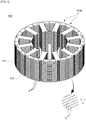
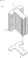
- FIG. 4 is a perspective view illustrating the stator core of the motor according to the embodiment.
- the stator core 410 may be formed in a form in which a plurality of thin steel sheets S are stacked on each other. Accordingly, when the adhesive member B fills the holes H, the adhesive member B may penetrate between the sheets S to reduce noise and vibration of the motor 1.
- each of the plurality of sheets S may have a predetermined thickness T in the shaft direction. In this case, the thickness T may be 0.5 mm.
- the yokes 411 may be formed in a cylindrical shape.
- the plurality of teeth 412 may be disposed to protrude from an inner circumferential surface of the yokes 411 in the radial direction.
- the teeth 412 may be disposed to be spaced apart from each other in the circumferential direction. Accordingly, slots may be formed between the teeth 412 for winding the coils 430.
- the coil 430 may be wound around the tooth 412.
- the insulator 420 may be disposed between the tooth 412 and the coil 430 to insulate the tooth 412 from the coil 430.
- the plurality of holes H may be disposed in the yokes 411 to be spaced apart from each other in the circumferential direction.
- the holes H may be formed in the yokes 411 to pass through the yokes 411 in the shaft direction but are not necessarily limited thereto.
- the holes H may be disposed on virtual lines L each extending along a corresponding side surface 413 of the teeth 412 in the radial direction. Accordingly, when viewed in the radial direction, the holes H may be disposed to overlap the side surfaces 413 of the teeth 412.
- two holes H may also be provided to correspond to the side surfaces 413 of the tooth 412.
- a center C2 of the hole H may be disposed on the line L but is not necessarily limited thereto.
- the hole H may also be disposed in the yoke 411 in a range in which an outer diameter of the hole H does not deviate the line L.
- the line L may be parallel to a virtual line L1 connecting a center C of the rotor 300 and a center C1 of the tooth 412.
- the two holes H may be symmetrically disposed on the basis of the line L1, and a distance D1 from the line L1 to the center C2 of the hole may be the same as a distance from the line L1 to the side surface 413 of the tooth 412.
- a diameter D of the hole H may be greater than or equal to two times and less than three times the thickness T of the sheet S in the shaft direction. Accordingly, when the thickness T of the sheet S is 0.5 mm, the diameter D of the hole H may be in the range of ⁇ 1.0 ⁇ D ⁇ 1.5.
- the adhesive member B may penetrate between the sheets S.
- the adhesive member B may penetrate between the sheets S stacked in the shaft direction due to the capillary phenomenon.
- the adhesive member B filling the hole H may be glue having an anaerobic property. Accordingly, the adhesive member B may be cured without performing a curing process using thermal curing or ultraviolet curing. In addition, a viscosity of the adhesive member B may be 125 mPa.s or more and less than 800 mPa.s.
- the adhesive member B penetrates between the sheets S at high speed so that a section in which the adhesive member B is not applied is not present between the sheets S. That is, the adhesive member B may be applied between all the sheets S. However, in a case in which the viscosity of the adhesive member B is less than 125 mPa.s, the adhesive member B may be applied between the sheets S and leak to the outside.
- the viscosity of the adhesive member B is 800 mPa.s
- a section is formed in which the adhesive member B may not penetrate to an inner side of the tooth 412 through between the sheets S.
- the viscosity of the adhesive member B is 2000 mPa.s, since it takes a considerable amount of time for the adhesive member B to penetrate between the sheets S, workability is degraded, curing proceeds, and thus a section may be formed in which the adhesive member B does not penetrate between the sheets S, wherein the section may be half of an area of the sheet S.
- the adhesive member B which has a viscosity greater than or equal to 125 mPa.s and less than 800 mPa.s, of the motor 1 may be selected in consideration of penetration speed and the capillary phenomenon.
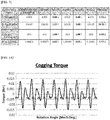
- FIG. 5 is a table comparing electrical performance variations according to the diameter of the hole formed in the stator core of the motor according to the embodiment
- FIGS. 6A to 6D are graphs showing a cogging torque of a comparative example and a cogging torque according to the diameter of the hole formed in the stator core of the motor according to the embodiment
- FIGS. 7A and 7D are graphs showing electrical performance variations according to the diameter of the hole formed in the stator core of the motor according to the embodiment.
- FIG. 6A is the graph showing the cogging torque of the comparative example
- FIG. 6B is the graph showing the cogging torque in a case in which the diameter of the hole formed in the stator core is ⁇ 1.0
- FIG. 6C is the graph showing the cogging torque in a case in which the diameter of the hole formed in the stator core is ⁇ 1.5
- FIG. 6D is the graph showing the cogging torque in a case in which the diameter of the hole formed in the stator core is ⁇ 2.0
- FIG. 7A is a graph showing a torque according to the change in diameter of the hole
- FIG. 7B is a graph showing a cogging torque according to the change in diameter
- FIG. 7C is a graph showing a ripple according to the change in diameter of the hole
- FIG. 7D is a graph showing a counter electromotive force according to the change in diameter of the hole.
- a motor provided as the comparative example is a motor in which a hole is not formed in a stator core.
- changes in electrical performance of experimented motors, each of which includes a rotor having ten magnets and a stator having twelve teeth, are compared, and the motor 1 is in a state in which the hole is not filled with the adhesive member.
- FIG. 8 is a table showing a reduction in vibration before and after filling with an adhesive member of the motor according to the embodiment when a viscosity of the adhesive member is 125 mPa.s.
- FIG. 9 is a table showing a reduction in vibration before and after filling with an adhesive member of the motor according to the embodiment when the viscosity of the adhesive member is 800 mPa.s.
- the viscosty of the adhesive member B filling the hole H is 800 mPa.s, the amplitude in the section between 3000 to 4000 Hz is decreased by about 51%.
- a plurality of unit stator cores 410a may be disposed in the circumferential direction to form the stator core 410.
- the unit stator core 410a including the holes H passing therethrough in the shaft direction may be referred to as a first unit stator core.
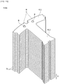
- FIG. 10 is a perspective view illustrating the unit stator core of the motor according to the embodiment
- FIG. 11 is a plan view illustrating the unit stator core of the motor according to the embodiment
- FIG. 12 is a perspective view illustrating a sheet of the unit stator core of the motor according to the embodiment
- FIG. 13 is a view illustrating the adhesive member which permeates the unit stator core of the motor according to the embodiment.
- the unit stator core 410a may be formed by stacking sheets Sa including yokes 411a having an arc shape and teeth 412a protruding from the yokes 411a in the radial direction and filling the holes with the adhesive member B.
- the holes H may be formed in the yoke 411a.
- the sheet Sa in which the holes H are formed to form the unit stator core 410a may be referred to as a first sheet.
- the adhesive member B may fill the holes H formed in the unit stator core 410a to penetrate between the sheets Sa. Accordingly, noise and vibration of the motor 1 may be reduced.
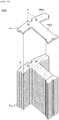
- FIG. 14 is a perspective view illustrating another example of the unit stator core of the motor according to the embodiment.
- a plurality of unit stator cores 410b may be disposed in the circumferential direction to form the stator core 410.
- the unit stator core 410b When the unit stator core 410b is compared to the first unit stator core which is the unit stator core 410a including the holes H passing therethrough in the shaft direction, there is a difference in that the unit stator core 410b, which is another example thereof, further includes a second sheet Sb which blocks the holes at a lower side of the unit stator core 410b. Accordingly, the unit stator core 410b which is another example thereof may be referred to as a second unit stator core.
- the unit stator core 410b which is another example thereof, may include the plurality of first sheets Sa in which the holes H are formed and one second sheet Sb disposed below the first sheets Sa.
- the holes H are not present in the second sheet Sb.
- the second sheet Sb may block the holes H of the plurality of first sheets Sa, which are disposed to be stacked, to prevent the adhesive member B from leaking to a lower side of the unit stator core 410b.
- FIG. 15 is a view illustrating still another example of the stator core of the motor according to the embodiment.
- the unit stator cores 410a or 410b are disposed in the circumferential direction to form the above-described stator core 410, but the present invention is not necessarily limited thereto.
- the stator core 410 may also be formed by stacking sheets Sc including a yoke 411b having a ring shape and a plurality of teeth 412b protruding from the yoke 411b in the radial direction.
- each of the plurality of sheets Sc may have a predetermined thickness T in the shaft direction.
- the thickness T may be 0.5 mm.
- stator core 410 is formed using the unit stator cores 410a or 410b
- adhesive member B may penetrate along contact surfaces between the unit stator cores 410a or 410b in the shaft direction according to the viscosity of adhesive member B, noise and vibration of the motor 1 may decrease further.
- the adhesive member B when the adhesive member B fills the holes H in a state in which the plurality of unit stator cores 410a or 410b are disposed in the circumferential direction, and the plurality of unit stator cores 410a or 410b are temporarily assembled through a spot-welding method or the like, the adhesive member B may penetrate between the sheets Sa and permeate along contact surfaces between the unit stator cores 410a or 410b in the shaft direction.
- the tooth 412 may be disposed to face the magnet 320 of the rotor 300.
- the coil 430 is wound around each of the teeth 412.
- the insulator 420 may be formed of a synthetic resin material to insulate the stator core 410 from the coil 430.
- the coil 430 may be wound around the stator core 410 on which the insulator 420 is disposed. In addition, the coil 430 may generate a rotating magnetic field when power is supplied thereto.
- the insulators 420 may be coupled to an upper side and a lower side of the stator core 410.
- the insulators 420 may also be formed as one single product to be coupled to the stator core 410.
- a plurality of unit insulators may also be formed as the insulators 420 so that the insulators 420 are disposed on the stator core 410 in the circumferential direction.
- the shaft 500 may be rotatably supported by the bearings 10 in the housing 100.
- the shaft 500 may be rotated in conjunction with the rotation of the rotor 300.
- the busbar 600 may be disposed on the stator 400.
- busbar 600 may be electrically connected to the coil 430 of the stator 400.
- the busbar 600 may include a busbar body and a plurality of terminals disposed in the busbar body.
- the busbar body may be a mold product formed through an injection molding process.
- each of the terminals may be electrically connected to the coil 430 of the stator 400.
- the sensor part 700 may detect a magnetic force of a sensing magnet installed to rotate in conjunction with the rotor 300 to check a present position of the rotor 300 so as to detect rotation of the shaft 500.
- the sensor part 700 may include a sensing magnet assembly 710 and a printed circuit board (PCB) 720.
- PCB printed circuit board
- the sensing magnet assembly 710 is coupled to the shaft 500 to rotate in conjunction with the rotor 300 so as to detect a position of the rotor 300.
- the sensing magnet assembly 710 may include sensing magnets and a sensing plate. The sensing magnets and the sensing plate may be coaxially coupled.
- the sensing magnets may include main magnets disposed close to a hole forming an inner circumferential surface thereof in the circumferential direction and sub-magnets.
- the main magnets may be arranged like the drive magnets inserted into the rotor 300 of the motor.
- the sub-magnets may be divided further than the main magnets so that the sub-magnets may be formed to have poles of which the number is greater than the number of poles of the main magnets. Accordingly, a rotation angle may be divided and measured more precisely, and thus the motor may be driven more smoothly.
- the sensing plate may be formed of a metal material having a disc shape.
- the sensing magnet may be coupled to an upper surface of the sensing plate.
- the sensing plate may be coupled to the shaft 500. In this case, a hole through which the shaft 500 passes may be formed in the sensing plate.
- a sensor configured to detect a magnetic force of the sensing magnets may be disposed on the PCB 720.
- a Hall integrated circuit IC
- the sensor may detect changes in an N-pole and an S-pole of the sensing magnet to generate a sensing signal.
- MOTOR 100 HOUSING 200: COVER 300: ROTOR 310: ROTOR CORE 320: MAGNET 400: STATOR 410: STATOR CORE 430: COIL 500: SHAFT 600: BUSBAR 700: SENSOR PART
Landscapes
- Engineering & Computer Science (AREA)
- Power Engineering (AREA)
- Manufacturing & Machinery (AREA)
- Iron Core Of Rotating Electric Machines (AREA)
Abstract
Description
- The present invention relates to a motor.
- Motors are apparatuses configured to convert electrical energy to mechanical energy to obtain rotational forces and are widely used for vehicles, home appliances, industrial machines, and the like.
- Particularly, as more electric devices are used in a vehicle, demands for a motor applied to a steering system, a braking system, a machinery system, and the like are significantly increasing.
- A motor may include a housing, a shaft, a stator disposed on an inner circumferential surface of the housing, a rotor disposed on an outer circumferential surface of the shaft, and the like. In this case, an electrical interaction is induced between the stator and the rotor so that the rotor rotates.
- The rotor may include a rotor core and a plurality of magnets disposed on the rotor core. In the case of such a multi-pole motor, there is a problem in that loud noise and a great deal of vibration occur.
- Although the stator may be over-molded to reduce the noise and vibration, there is a problem in that a production cost increases.
- Accordingly, there is a need for a motor with a structure allowing production efficiency of the motor to be increased and the noise and vibration to also be reduced.
- The present invention is directed to providing a motor to which a robust design using an adhesive member such as glue is applied when sheets are stacked to form a stator core, thereby reducing noise and vibration.
- Objectives to be solved by the present invention are not limited to the above-described objectives, and other objectives which are not described above will be clearly understood by those skilled in the art from the following specification.
- One aspect of the present invention provides a motor including a shaft, a rotor coupled to the shaft, and a stator disposed outside the rotor, wherein the stator includes a stator core formed by arranging a plurality of unit stator cores in a circumferential direction and a coil wound around the stator core, the unit stator core formed by stacking a plurality of sheets includes a yoke including a plurality of holes, a tooth protruding from the yoke in a radial direction, and an adhesive member disposed in the plurality of holes, and each of the plurality of holes is disposed on a virtual line (L) extending along one of both side surfaces of the tooth in the radial direction.
- The line (L) may be parallel to a virtual line (L1) connecting a center (C) of the rotor and a center (C1) of the tooth.
- The holes may be symmetrically disposed on the basis of the line (LI), and when viewed from above, a distance from the line (L1) to a center (C2) of the hole may be the same as a distance from the line (L1) to the side surface of the tooth.
- Some amount of the adhesive member disposed in the plurality of holes may be disposed between the plurality of sheets. For example, when the adhesive member fills the holes, the adhesive member may penetrate between the sheets.
- A diameter of each of the plurality of holes may be greater than two times and less than three times a thickness of each of the plurality of sheets. For example, when the thickness of the sheet in the shaft direction is 0.5 mm, a diameter of the hole may be greater than two times and less than three times the thickness.
- A center (C2) of the hole may be disposed on the line (L).
- The adhesive member may have an anaerobic property. In this case, a viscosity of the adhesive member may be greater than or equal to 125 mPa.s and less than 800 mPa.s.
- The plurality of sheets forming at least one unit stator core among the plurality of unit stator cores may be formed by stacking a plurality of first sheets including the plurality of holes and a second sheet in which the hole is not formed.
- The second sheet may be disposed on a lower surface of the first sheet disposed as a lowermost layer among the plurality of first sheets and may block the holes of the plurality of first sheets.
- The holes may be symmetrically disposed on the basis of the virtual line (L1) connecting the center (C) of the rotor and the center (C1) of the tooth.
- When viewed in the radial direction, the hole may be disposed to overlap the side surface of the tooth.
- In addition, twelve teeth may be provided, and ten magnets of the rotor may be provided.
- According to embodiments, a motor to which a robust design is applied can be formed to reduce noise and vibration, wherein the robust design can be implemented by stacking sheets to form a stator core and filling holes formed in the stator core with an adhesive member. Particularly, in the case of a multi-pole motor having ten poles and twelve slots, since louder noise and more vibration occur when compared to other motors, the noise and vibration of the motor can be reduced by filling the holes formed in the stator core with the adhesive member.
- Although the robust design may be implemented by applying the adhesive member on the sheets and stacking the sheets, a cost and a time for a process increase. Accordingly, in the motor according to the embodiment, the adhesive member can penetrate between the sheets through the holes formed in the stator core to reduce the noise and vibration and also reduce a production cost.
- In this case, the noise and vibration of the motor can be reduced further according to a viscosity of the adhesive member.
- Various useful advantages and effects of the embodiments are not limited to the above-described contents and will be more easily understood from descriptions of the specific embodiments.
-
-
FIG. 1 is a view illustrating a motor according to an embodiment. -
FIG. 2 is a view illustrating a rotor and a stator of the motor according to the embodiment. -
FIG. 3 is a view illustrating an arrangement relationship between the rotor and a stator core of the motor according to the embodiment. -
FIG. 4 is a perspective view illustrating the stator core of the motor according to the embodiment. -
FIG. 5 is a performance comparison table according to a diameter of a hole formed in the stator core of the motor according to the embodiment. -
FIG. 6A is a graph showing a cogging torque of a comparative example. -
FIG. 6B is a graph showing a cogging torque in a case in which the diameter of the hole formed in the stator core of the motor according to the embodiment is ϕ1.0. -
FIG. 6C is a graph showing a cogging torque in a case in which the diameter of the hole formed in the stator core of the motor according to the embodiment is ϕ1.5. -
FIG. 6D is a graph showing a cogging torque in a case in which the diameter of the hole formed in the stator core of the motor according to the embodiment is ϕ2.0. -
FIG. 7A is a graph showing a torque according to a change in diameter of the hole of the motor according to the embodiment. -
FIG. 7B is a graph showing a cogging torque according to the change in diameter of the hole of the motor according to the embodiment. -
FIG. 7C is a graph showing a ripple according to the change in diameter of the hole of the motor according to the embodiment. -
FIG. 7D is a graph showing a counter electromotive force according to the change in diameter of the hole of the motor according to the embodiment. -
FIG. 8 is a table showing a reduction in vibration before and after filling with an adhesive member of the motor according to the embodiment when a viscosity of the adhesive member is 125 mPa.s. -
FIG. 9 is a table showing a reduction in vibration before and after filling with an adhesive member of the motor according to the embodiment when the viscosity of the adhesive member is 800 mPa.s. -
FIG. 10 is a perspective view illustrating a unit stator core of the motor according to the embodiment. -
FIG. 11 is a plan view illustrating the unit stator core of the motor according to the embodiment. -
FIG. 12 is a perspective view illustrating a sheet of the unit stator core of the motor according to the embodiment. -
FIG. 13 is a view illustrating an adhesive member which permeates the unit stator core of the motor according to the embodiment. -
FIG. 14 is a perspective view illustrating another example of the unit stator core of the motor according to the embodiment. -
FIG. 15 is a view illustrating still another example of the stator core of the motor according to the embodiment. - Hereinafter, exemplary embodiments of the present invention will be described in detail with reference to the accompanying drawings.
- However, the technical spirit of the present invention is not limited to some embodiments which will be described and may be realized using various other embodiments, and at least one component of the embodiments may be selectively coupled, substituted, and used to realize the technical spirit within the range of the technical spirit.
- In addition, unless clearly and specifically defined otherwise by context, all terms (including technical and scientific terms) used herein can be interpreted as having customary meanings to those skilled in the art, and meanings of generally used terms, such as those defined in commonly used dictionaries, will be interpreted by considering contextual meanings of the related technology.
- In addition, the terms used in the embodiments of the present invention are considered in a descriptive sense and not for limiting the present invention.
- In the present specification, unless clearly indicated otherwise by the context, singular forms include the plural forms thereof, and in a case in which "at least one (or one or more) among A, B, and C" is described, this may include at least one combination among all possible combinations of A, B, and C.
- In addition, in descriptions of components of the present invention, terms such as "first," "second," "A," "B," "(a)," and "(b)" can be used.
- The terms are only to distinguish one element from another element, and an essence, order, and the like of the element are not limited by the terms.
- In addition, it should be understood that, when an element is referred to as being "connected or coupled" to another element, such a description may include both of a case in which the element is directly connected or coupled to another element and a case in which the element is connected or coupled to another element with still another element disposed therebetween.
- In addition, in a case in which any one element is described as being formed or disposed "on or under" another element, such a description includes both a case in which the two elements are formed or disposed in direct contact with each other and a case in which one or more other elements are interposed between the two elements. In addition, when one element is described as being disposed "on or under" another element, such a description may include a case in which the one element is disposed at an upper side or a lower side with respect to another element.
- Hereinafter, example embodiments of the invention will be described in detail with reference to the accompanying drawings. Components that are the same or correspond to each other will be denoted by the same reference numerals regardless of the figure numbers, and redundant descriptions will be omitted.
-
FIG. 1 is a view illustrating a motor according to an embodiment,FIG. 2 is a view illustrating a rotor and a stator of the motor according to the embodiment, andFIG. 3 is a view illustrating an arrangement relationship between the rotor and a stator core of the motor according to the embodiment. InFIG. 1 , an x direction may be referred to as a shaft direction and a y direction may be referred to as a radial direction. In addition, the shaft direction may be perpendicular to the radial direction. In this case, the stator core illustrated inFIG. 3 may be in a state before a hole is filled with an adhesive member. - Referring to
FIGS. 1 and2 , amotor 1 according to the embodiment includes ahousing 100 in which an opening is formed at one side, acover 200 disposed on thehousing 100, arotor 300 coupled to ashaft 500, astator 400 disposed in thehousing 100, theshaft 500 configured to rotate with therotor 300, abusbar 600 disposed on thestator 400, and asensor part 700 configured to detect rotation of therotor 300. In this case, therotor 300 of themotor 1 may include tenmagnets 320, and thestator 400 may include twelveteeth 412. - In this case, a
stator core 410 of thestator 400 may be formed by stacking a plurality of sheets S in the shaft direction. In addition, an adhesive member B may penetrate between the sheets S by filling holes H formed in thestator core 410. Accordingly, in themotor 1, noise and vibration may be reduced due to the adhesive member B penetrating between the sheets S. - The
motor 1 may be a motor used in an electronic power steering (EPS) system. The EPS system may assist a steering force using a driving force of the motor to secure turning stability and provide a rapid restoring force of a vehicle. Accordingly, a driver of the vehicle can travel safely. - The
housing 100 and thecover 200 may form an exterior of themotor 1. In addition, thehousing 100 may be coupled to thecover 200 to form an accommodation space. Accordingly, as illustrated inFIG. 1 , therotor 300, thestator 400, theshaft 500, thebusbar 600, thesensor part 700, and the like may be disposed in the accommodation space. In this case, theshaft 500 is rotatably disposed in the accommodation space. Accordingly, themotor 1 may further includebearings 10 disposed on an upper portion and a lower portion of theshaft 500. - The
housing 100 may be formed in a cylindrical shape. In addition, therotor 300, thestator 400, and the like may be accommodated in thehousing 100. In this case, the shape or material of thehousing 100 may be variously changed. For example, thehousing 100 may be formed of a metal material which firmly withstands even at high temperature. - The
cover 200 may be disposed on an open surface of thehousing 100, that is, an upper portion of thehousing 100, to cover an opening of thehousing 100. - Referring to
FIGS. 1 to 3 , therotor 300 may be disposed inside thestator 400, and theshaft 500 may be coupled to a central portion of therotor 300 through a press-fitting method. In this case, the term "inside" may be referred to as a direction toward a center C, and the term "outside" may be referred to as a direction opposite to the term "inside." - In addition, the
rotor 300 may be rotatably disposed inside thestator 400. - Referring to
FIGS. 2 and3 , therotor 300 may include arotor core 310 and a plurality ofmagnets 320 disposed on an outer circumferential surface of therotor core 310 in a circumferential direction. - As illustrated in
FIG. 3 , tenmagnets 320 may be disposed on the outer circumferential surface of therotor core 310 to be spaced apart from each other at preset intervals. In this case, themagnets 320 may be referred to as rotor magnets or drive magnets. In this case, an example in which the plurality ofmagnets 320 are disposed on the outer circumferential surface of therotor core 310 of therotor 300 is illustrated, but the present invention is not necessarily limited thereto. For example, therotor 300 may also be formed as an interior permanent magnet (IPM) rotor in whichmagnets 320 are disposed in arotor core 310. - The
rotor core 310 may be formed in a form in which a plurality of circular thin steel plates are stacked on each other or a single cylindrical form. In addition, a hole coupled to theshaft 500 may be formed at a center C of therotor core 310. - The
magnets 320 generate a rotating magnetic field withcoils 430 wound around thestator core 410 of thestator 400. Themagnets 320 may be disposed so that an N-pole and an S-pole are alternately disposed around theshaft 500 in the circumferential direction. - Accordingly, due to an electrical interaction between the
coils 430 and themagnets 320, therotor 300 is rotated, and theshaft 500 is rotated in conjunction with the rotation of therotor 300 so that a driving force of themotor 1 is generated. - Meanwhile, the
rotor 300 may further include a can (not shown) disposed to cover therotor core 310 to which themagnets 320 are attached. - The can may protect the
rotor core 310 and themagnets 320 from external shocks and physical and chemical stimuli while preventing foreign materials from being introduced to therotor core 310 andmagnets 320. - In addition, the can prevents the
magnets 320 from being separated from therotor core 310. - The
stator 400 may be disposed inside thehousing 100. In this case, thestator 400 may be coupled to thehousing 100 through a hot press fitting method. Accordingly, thestator 400 may be supported by an inner circumferential surface of thehousing 100. In addition, thestator 400 is disposed outside therotor 300. That is, therotor 300 may be rotatably disposed inside thestator 400. - Referring to
FIGS. 1 and2 , thestator 400 may include thestator core 410,insulators 420 disposed on thestator core 410, and thecoils 430 wound around theinsulators 420. In this case, theinsulators 420 may be disposed between thestator core 410 and thecoils 430 to insulate thecoils 430. - The
coils 430 configured to generate a rotating magnetic field may be wound around thestator core 410. - The
stator core 410 may includeyokes 411 in which holes H are formed,teeth 412 protruding from theyokes 411 in the radial direction, and the adhesive member B disposed in the holes H. -
FIG. 4 is a perspective view illustrating the stator core of the motor according to the embodiment. - Referring to
FIG. 4 , thestator core 410 may be formed in a form in which a plurality of thin steel sheets S are stacked on each other. Accordingly, when the adhesive member B fills the holes H, the adhesive member B may penetrate between the sheets S to reduce noise and vibration of themotor 1. In this case, each of the plurality of sheets S may have a predetermined thickness T in the shaft direction. In this case, the thickness T may be 0.5 mm. - The
yokes 411 may be formed in a cylindrical shape. In addition, the plurality ofteeth 412 may be disposed to protrude from an inner circumferential surface of theyokes 411 in the radial direction. In this case, theteeth 412 may be disposed to be spaced apart from each other in the circumferential direction. Accordingly, slots may be formed between theteeth 412 for winding thecoils 430. - In addition, the
coil 430 may be wound around thetooth 412. In this case, theinsulator 420 may be disposed between thetooth 412 and thecoil 430 to insulate thetooth 412 from thecoil 430. - The plurality of holes H may be disposed in the
yokes 411 to be spaced apart from each other in the circumferential direction. In this case, the holes H may be formed in theyokes 411 to pass through theyokes 411 in the shaft direction but are not necessarily limited thereto. - Referring to
FIG. 3 , the holes H may be disposed on virtual lines L each extending along acorresponding side surface 413 of theteeth 412 in the radial direction. Accordingly, when viewed in the radial direction, the holes H may be disposed to overlap the side surfaces 413 of theteeth 412. - As illustrated in
FIG. 3 , since twoside surfaces 413 of thetooth 412 are provided, two holes H may also be provided to correspond to the side surfaces 413 of thetooth 412. - In this case, a center C2 of the hole H may be disposed on the line L but is not necessarily limited thereto. For example, the hole H may also be disposed in the
yoke 411 in a range in which an outer diameter of the hole H does not deviate the line L. - In this case, the line L may be parallel to a virtual line L1 connecting a center C of the
rotor 300 and a center C1 of thetooth 412. Accordingly, the two holes H may be symmetrically disposed on the basis of the line L1, and a distance D1 from the line L1 to the center C2 of the hole may be the same as a distance from the line L1 to theside surface 413 of thetooth 412. - Meanwhile, a diameter D of the hole H may be greater than or equal to two times and less than three times the thickness T of the sheet S in the shaft direction. Accordingly, when the thickness T of the sheet S is 0.5 mm, the diameter D of the hole H may be in the range of ϕ1.0≤D<ϕ1.5.
- In addition, since the holes H are filled with the adhesive member B, the adhesive member B may penetrate between the sheets S. For example, when the adhesive member B fills the holes H, the adhesive member B may penetrate between the sheets S stacked in the shaft direction due to the capillary phenomenon.
- In this case, the adhesive member B filling the hole H may be glue having an anaerobic property. Accordingly, the adhesive member B may be cured without performing a curing process using thermal curing or ultraviolet curing. In addition, a viscosity of the adhesive member B may be 125 mPa.s or more and less than 800 mPa.s.
- For example, in a case in which the viscosity of the adhesive member B is 125 mPa.s, the adhesive member B penetrates between the sheets S at high speed so that a section in which the adhesive member B is not applied is not present between the sheets S. That is, the adhesive member B may be applied between all the sheets S. However, in a case in which the viscosity of the adhesive member B is less than 125 mPa.s, the adhesive member B may be applied between the sheets S and leak to the outside.
- In addition, in a case in which the viscosity of the adhesive member B is 800 mPa.s, although the adhesive member B penetrates between the sheets S, a section is formed in which the adhesive member B may not penetrate to an inner side of the
tooth 412 through between the sheets S. In addition, the viscosity of the adhesive member B is 2000 mPa.s, since it takes a considerable amount of time for the adhesive member B to penetrate between the sheets S, workability is degraded, curing proceeds, and thus a section may be formed in which the adhesive member B does not penetrate between the sheets S, wherein the section may be half of an area of the sheet S. - Accordingly, the adhesive member B, which has a viscosity greater than or equal to 125 mPa.s and less than 800 mPa.s, of the
motor 1 may be selected in consideration of penetration speed and the capillary phenomenon. -
FIG. 5 is a table comparing electrical performance variations according to the diameter of the hole formed in the stator core of the motor according to the embodiment,FIGS. 6A to 6D are graphs showing a cogging torque of a comparative example and a cogging torque according to the diameter of the hole formed in the stator core of the motor according to the embodiment, andFIGS. 7A and7D are graphs showing electrical performance variations according to the diameter of the hole formed in the stator core of the motor according to the embodiment. -
FIG. 6A is the graph showing the cogging torque of the comparative example,FIG. 6B is the graph showing the cogging torque in a case in which the diameter of the hole formed in the stator core is ϕ1.0,FIG. 6C is the graph showing the cogging torque in a case in which the diameter of the hole formed in the stator core is ϕ1.5, andFIG. 6D is the graph showing the cogging torque in a case in which the diameter of the hole formed in the stator core is ϕ2.0. In addition,FIG. 7A is a graph showing a torque according to the change in diameter of the hole,FIG. 7B is a graph showing a cogging torque according to the change in diameter,FIG. 7C is a graph showing a ripple according to the change in diameter of the hole, andFIG. 7D is a graph showing a counter electromotive force according to the change in diameter of the hole. - In this case, a motor provided as the comparative example is a motor in which a hole is not formed in a stator core. In this case, changes in electrical performance of experimented motors, each of which includes a rotor having ten magnets and a stator having twelve teeth, are compared, and the
motor 1 is in a state in which the hole is not filled with the adhesive member. - Referring to
FIGS. 5 and6A to 6D , in a case in which the diameter D of the hole H is in the range of ϕ1.0≤D<ϕ1.5, it may be seen that changes in torque, cogging torque, ripple, and counter electromotive force of themotor 1 are insignificant. - Referring to
FIG. 7A , it may be seen that, when the diameter D of the hole H is in the range of ϕ1.0≤D<ϕ1.5, the torque is insignificantly decreased, but when the diameter D of the hole H is greater than ϕ1.5, a torque reduction rate increases. - Referring to
FIG. 7B , it may be seen that, when the diameter D of the hole H is in the range of ϕ1.0≤D<ϕ1.5, the cogging torque increases insignificantly, but when the diameter D of the hole H is greater than ϕ1.5, the cogging torque decreases sharply. However, it may be seen that when the values are considered, since the cogging torque decreases from 30 mNm to 28 mNm, when the diameter D of hole H is greater than ϕ1.5, the cogging torque decreases slightly. - Referring to
FIG. 7C , it may be seen that, when the diameter D of the hole H is in the range of ϕ1.0≤D<ϕ1.5, a ripple increases insignificantly, but when the diameter D of the hole H is greater than ϕ1.5, the ripple increases sharply. - Referring to
FIG. 7D , it may be seen that when the diameter D of the hole H is in the range of ϕ1.0≤D<ϕ1.5, a counter electromotive force decreases insignificantly, but when the diameter D of the hole H is greater than ϕ1.5, the counter electromotive force decreases sharply. -
FIG. 8 is a table showing a reduction in vibration before and after filling with an adhesive member of the motor according to the embodiment when a viscosity of the adhesive member is 125 mPa.s.FIG. 9 is a table showing a reduction in vibration before and after filling with an adhesive member of the motor according to the embodiment when the viscosity of the adhesive member is 800 mPa.s. - Referring to
FIG. 8 , it may be seen that when the viscosity of the adhesive member B filling the hole H is 125 mPa.s, an amplitude in a section between 3000 to 4000 Hz is decreased by about 54%. - Referring to
FIG. 9 , it may be seen that the viscosty of the adhesive member B filling the hole H is 800 mPa.s, the amplitude in the section between 3000 to 4000 Hz is decreased by about 51%. - Referring to
FIG. 4 , a plurality ofunit stator cores 410a may be disposed in the circumferential direction to form thestator core 410. In this case, theunit stator core 410a including the holes H passing therethrough in the shaft direction may be referred to as a first unit stator core. -
FIG. 10 is a perspective view illustrating the unit stator core of the motor according to the embodiment,FIG. 11 is a plan view illustrating the unit stator core of the motor according to the embodiment,FIG. 12 is a perspective view illustrating a sheet of the unit stator core of the motor according to the embodiment, andFIG. 13 is a view illustrating the adhesive member which permeates the unit stator core of the motor according to the embodiment. - Referring to
FIGS. 10 to 13 , theunit stator core 410a may be formed by stacking sheetsSa including yokes 411a having an arc shape andteeth 412a protruding from theyokes 411a in the radial direction and filling the holes with the adhesive member B. As illustrated inFIG. 12 , the holes H may be formed in theyoke 411a. In this case, the sheet Sa in which the holes H are formed to form theunit stator core 410a may be referred to as a first sheet. - Accordingly, as illustrated in
FIG. 13 , the adhesive member B may fill the holes H formed in theunit stator core 410a to penetrate between the sheets Sa. Accordingly, noise and vibration of themotor 1 may be reduced. -
FIG. 14 is a perspective view illustrating another example of the unit stator core of the motor according to the embodiment. - Referring to
FIG. 14 , a plurality ofunit stator cores 410b may be disposed in the circumferential direction to form thestator core 410. - When the
unit stator core 410b is compared to the first unit stator core which is theunit stator core 410a including the holes H passing therethrough in the shaft direction, there is a difference in that theunit stator core 410b, which is another example thereof, further includes a second sheet Sb which blocks the holes at a lower side of theunit stator core 410b. Accordingly, theunit stator core 410b which is another example thereof may be referred to as a second unit stator core. - Referring to
FIG. 14 , theunit stator core 410b, which is another example thereof, may include the plurality of first sheets Sa in which the holes H are formed and one second sheet Sb disposed below the first sheets Sa. In this case, the holes H are not present in the second sheet Sb. Accordingly, the second sheet Sb may block the holes H of the plurality of first sheets Sa, which are disposed to be stacked, to prevent the adhesive member B from leaking to a lower side of theunit stator core 410b. -
FIG. 15 is a view illustrating still another example of the stator core of the motor according to the embodiment. - In the examples, the
unit stator cores stator core 410, but the present invention is not necessarily limited thereto. - As illustrated in
FIG. 15 , thestator core 410 may also be formed by stacking sheets Sc including ayoke 411b having a ring shape and a plurality ofteeth 412b protruding from theyoke 411b in the radial direction. In this case, each of the plurality of sheets Sc may have a predetermined thickness T in the shaft direction. In this case, the thickness T may be 0.5 mm. - However, in the case in which the
stator core 410 is formed using theunit stator cores unit stator cores motor 1 may decrease further. - For example, when the adhesive member B fills the holes H in a state in which the plurality of
unit stator cores unit stator cores unit stator cores - Meanwhile, the
tooth 412 may be disposed to face themagnet 320 of therotor 300. In addition, thecoil 430 is wound around each of theteeth 412. - The
insulator 420 may be formed of a synthetic resin material to insulate thestator core 410 from thecoil 430. - In addition, the
coil 430 may be wound around thestator core 410 on which theinsulator 420 is disposed. In addition, thecoil 430 may generate a rotating magnetic field when power is supplied thereto. - The
insulators 420 may be coupled to an upper side and a lower side of thestator core 410. In this case, theinsulators 420 may also be formed as one single product to be coupled to thestator core 410. Alternatively, a plurality of unit insulators may also be formed as theinsulators 420 so that theinsulators 420 are disposed on thestator core 410 in the circumferential direction. - As illustrated in
FIG. 1 , theshaft 500 may be rotatably supported by thebearings 10 in thehousing 100. In addition, theshaft 500 may be rotated in conjunction with the rotation of therotor 300. - The
busbar 600 may be disposed on thestator 400. - In addition, the
busbar 600 may be electrically connected to thecoil 430 of thestator 400. - The
busbar 600 may include a busbar body and a plurality of terminals disposed in the busbar body. In this case, the busbar body may be a mold product formed through an injection molding process. In addition, each of the terminals may be electrically connected to thecoil 430 of thestator 400. - The
sensor part 700 may detect a magnetic force of a sensing magnet installed to rotate in conjunction with therotor 300 to check a present position of therotor 300 so as to detect rotation of theshaft 500. - The
sensor part 700 may include asensing magnet assembly 710 and a printed circuit board (PCB) 720. - The
sensing magnet assembly 710 is coupled to theshaft 500 to rotate in conjunction with therotor 300 so as to detect a position of therotor 300. In this case, thesensing magnet assembly 710 may include sensing magnets and a sensing plate. The sensing magnets and the sensing plate may be coaxially coupled. - The sensing magnets may include main magnets disposed close to a hole forming an inner circumferential surface thereof in the circumferential direction and sub-magnets.
- The main magnets may be arranged like the drive magnets inserted into the
rotor 300 of the motor. - The sub-magnets may be divided further than the main magnets so that the sub-magnets may be formed to have poles of which the number is greater than the number of poles of the main magnets. Accordingly, a rotation angle may be divided and measured more precisely, and thus the motor may be driven more smoothly.
- The sensing plate may be formed of a metal material having a disc shape. The sensing magnet may be coupled to an upper surface of the sensing plate. In addition, the sensing plate may be coupled to the
shaft 500. In this case, a hole through which theshaft 500 passes may be formed in the sensing plate. - A sensor configured to detect a magnetic force of the sensing magnets may be disposed on the
PCB 720. In this case, a Hall integrated circuit (IC) may be provided as the sensor. In addition, the sensor may detect changes in an N-pole and an S-pole of the sensing magnet to generate a sensing signal. - While the present invention has been described with reference to the exemplary embodiments thereof, it will be understood by those skilled in the art that various changes in form and details may be made therein without departing from the spirit and scope of the invention as defined by the appended claims.
-
1: MOTOR 100: HOUSING 200: COVER 300: ROTOR 310: ROTOR CORE 320: MAGNET 400: STATOR 410: STATOR CORE 430: COIL 500: SHAFT 600: BUSBAR 700: SENSOR PART
Claims (9)
- A motor comprising:a shaft;a rotor coupled to the shaft; anda stator disposed outside the rotor,wherein the stator includes a stator core formed by arranging a plurality of unit stator cores in a circumferential direction and a coil wound around the stator core,wherein the unit stator core formed by stacking a plurality of sheets includes a yoke including a plurality of holes, a tooth protruding from the yoke in a radial direction, and an adhesive member disposed in the plurality of holes,wherein each of the plurality of holes is disposed on a virtual line (L) extending along one of both side surfaces of the tooth in the radial direction.
- The motor of claim 1, wherein the line (L) is parallel to a virtual line (L1) connecting a center (C) of the rotor and a center (C1) of the tooth.
- The motor of claim 2, wherein:the plurality of holes are symmetrically disposed on the basis of the line (L1); andwhen viewed from above, a distance from the line (L1) to a center (C2) of the hole is the same as a distance from the line (L1) to the side surface of the tooth.
- The motor of claim 1, wherein some amount of the adhesive member disposed in the plurality of holes is disposed between the plurality of sheets.
- The motor of any one of claims 1 to 4, wherein a diameter of each of the plurality of holes is greater than two times and less than three times a thickness of each of the plurality of sheets.
- The motor of claim 5, wherein the thickness of each of the plurality of sheets is 0.5 mm.
- The motor of claim 5, wherein a viscosity of the adhesive member is greater than or equal to 125 mPa.s and less than 800 mPa.s.
- The motor of claim 1, wherein the plurality of sheets forming at least one unit stator core among the plurality of unit stator cores are formed by stacking a plurality of first sheets including the plurality of holes and a second sheet in which the hole is not formed.
- The motor of claim 8, wherein the second sheet is disposed on a lower surface of the first sheet disposed as a lowermost layer among the plurality of first sheets and blocks the holes of the plurality of first sheets.
Applications Claiming Priority (2)
| Application Number | Priority Date | Filing Date | Title |
|---|---|---|---|
| KR1020180102692A KR102633273B1 (en) | 2018-08-30 | 2018-08-30 | Motor |
| PCT/KR2019/010883 WO2020045937A1 (en) | 2018-08-30 | 2019-08-27 | Motor |
Publications (3)
| Publication Number | Publication Date |
|---|---|
| EP3846319A1 true EP3846319A1 (en) | 2021-07-07 |
| EP3846319A4 EP3846319A4 (en) | 2021-10-27 |
| EP3846319B1 EP3846319B1 (en) | 2025-07-02 |
Family
ID=69644628
Family Applications (1)
| Application Number | Title | Priority Date | Filing Date |
|---|---|---|---|
| EP19855533.6A Active EP3846319B1 (en) | 2018-08-30 | 2019-08-27 | Motor |
Country Status (6)
| Country | Link |
|---|---|
| US (1) | US11799338B2 (en) |
| EP (1) | EP3846319B1 (en) |
| JP (2) | JP7477499B2 (en) |
| KR (1) | KR102633273B1 (en) |
| CN (1) | CN112640257B (en) |
| WO (1) | WO2020045937A1 (en) |
Cited By (1)
| Publication number | Priority date | Publication date | Assignee | Title |
|---|---|---|---|---|
| JP2023069847A (en) * | 2021-11-08 | 2023-05-18 | ニデック株式会社 | stator and motor |
Families Citing this family (2)
| Publication number | Priority date | Publication date | Assignee | Title |
|---|---|---|---|---|
| JP2021191039A (en) * | 2020-05-26 | 2021-12-13 | 日本電産株式会社 | Manufacturing method of laminated iron core |
| KR20260029747A (en) * | 2024-08-26 | 2026-03-05 | 엘지이노텍 주식회사 | Motor for vehicle |
Family Cites Families (17)
| Publication number | Priority date | Publication date | Assignee | Title |
|---|---|---|---|---|
| JP4747423B2 (en) * | 2001-03-02 | 2011-08-17 | パナソニック株式会社 | Electric motor |
| JP4046521B2 (en) * | 2002-03-13 | 2008-02-13 | 株式会社三井ハイテック | Laminated iron core and stator manufacturing method using the same |
| JP4210839B2 (en) | 2003-02-28 | 2009-01-21 | 株式会社安川電機 | Method for manufacturing motor stator piece |
| DE102009048116A1 (en) * | 2009-10-02 | 2011-04-07 | Brose Fahrzeugteile GmbH & Co. Kommanditgesellschaft, Würzburg | Brushless synchronous motor |
| JP2012023944A (en) * | 2010-06-15 | 2012-02-02 | Alphana Technology Co Ltd | Rotary apparatus |
| JP5442585B2 (en) * | 2010-11-25 | 2014-03-12 | 三菱電機株式会社 | Electric motor stator and method of manufacturing the same |
| JP2012120299A (en) * | 2010-11-30 | 2012-06-21 | Mitsubishi Electric Corp | Stator core, rotary electric machine, and manufacturing method of stator core |
| JP2013094020A (en) * | 2011-10-27 | 2013-05-16 | Suzuki Motor Corp | Electric rotary machine |
| JP5623498B2 (en) * | 2012-12-28 | 2014-11-12 | 三菱電機株式会社 | Stator core and stator, electric motor and compressor |
| JP6406788B2 (en) | 2014-01-10 | 2018-10-17 | 株式会社三井ハイテック | Manufacturing method of laminated iron core |
| JP6188639B2 (en) | 2014-06-13 | 2017-08-30 | 三菱電機株式会社 | Electric motor |
| JP6649676B2 (en) * | 2014-10-03 | 2020-02-19 | 株式会社三井ハイテック | Manufacturing method of laminated core |
| JP6279442B2 (en) * | 2014-10-03 | 2018-02-14 | 矢崎総業株式会社 | Fault detection system |
| JP5866081B1 (en) | 2015-02-18 | 2016-02-17 | 三菱電機株式会社 | Rotating electric machine and insulator for rotating electric machine |
| JP6432397B2 (en) * | 2015-03-12 | 2018-12-05 | アイシン・エィ・ダブリュ株式会社 | Motor manufacturing method and motor core |
| CN205864096U (en) * | 2016-08-02 | 2017-01-04 | 天津市佳利电梯电机有限公司 | A kind of stator stalloy |
| CN109643915B (en) * | 2016-09-05 | 2021-09-03 | Lg伊诺特有限公司 | Stator and motor including the same |
-
2018
- 2018-08-30 KR KR1020180102692A patent/KR102633273B1/en active Active
-
2019
- 2019-08-27 JP JP2021510307A patent/JP7477499B2/en active Active
- 2019-08-27 CN CN201980057070.1A patent/CN112640257B/en active Active
- 2019-08-27 US US17/270,771 patent/US11799338B2/en active Active
- 2019-08-27 EP EP19855533.6A patent/EP3846319B1/en active Active
- 2019-08-27 WO PCT/KR2019/010883 patent/WO2020045937A1/en not_active Ceased
-
2024
- 2024-04-18 JP JP2024067395A patent/JP7728916B2/en active Active
Cited By (1)
| Publication number | Priority date | Publication date | Assignee | Title |
|---|---|---|---|---|
| JP2023069847A (en) * | 2021-11-08 | 2023-05-18 | ニデック株式会社 | stator and motor |
Also Published As
| Publication number | Publication date |
|---|---|
| US20210336493A1 (en) | 2021-10-28 |
| EP3846319A4 (en) | 2021-10-27 |
| KR102633273B1 (en) | 2024-02-05 |
| JP7728916B2 (en) | 2025-08-25 |
| CN112640257B (en) | 2024-03-05 |
| JP2021535714A (en) | 2021-12-16 |
| KR20200025405A (en) | 2020-03-10 |
| JP2024099651A (en) | 2024-07-25 |
| JP7477499B2 (en) | 2024-05-01 |
| CN112640257A (en) | 2021-04-09 |
| WO2020045937A1 (en) | 2020-03-05 |
| EP3846319B1 (en) | 2025-07-02 |
| US11799338B2 (en) | 2023-10-24 |
Similar Documents
| Publication | Publication Date | Title |
|---|---|---|
| US11942823B2 (en) | Motor | |
| JP7728916B2 (en) | motor | |
| EP2680403B1 (en) | Electric motor and production method for the electric motor | |
| EP3855601B1 (en) | Motor | |
| CN109428407B (en) | Stator core | |
| US11942849B2 (en) | Motor | |
| WO2018225296A1 (en) | Rotor and rotary machine | |
| US11451116B2 (en) | Motor | |
| US12438413B2 (en) | Motor | |
| US12088172B2 (en) | Motor | |
| US11757318B2 (en) | Rotor and motor having same | |
| JP4627701B2 (en) | Rotating electric machine | |
| EP3731377B1 (en) | Rotor and motor having same | |
| KR102441899B1 (en) | Motor | |
| KR20180089173A (en) | Motor | |
| JPH0526922Y2 (en) | ||
| KR20190034935A (en) | Motor | |
| KR20220086181A (en) | Rotor and motor having the same | |
| JP2025179628A (en) | Manufacturing method of stator for axial gap motor and stator for axial gap motor | |
| JP2021069200A (en) | Laminated steel sheet and manufacturing method of the same |
Legal Events
| Date | Code | Title | Description |
|---|---|---|---|
| STAA | Information on the status of an ep patent application or granted ep patent |
Free format text: STATUS: THE INTERNATIONAL PUBLICATION HAS BEEN MADE |
|
| STAA | Information on the status of an ep patent application or granted ep patent |
Free format text: STATUS: REQUEST FOR EXAMINATION WAS MADE |
|
| PUAI | Public reference made under article 153(3) epc to a published international application that has entered the european phase |
Free format text: ORIGINAL CODE: 0009012 |
|
| 17P | Request for examination filed |
Effective date: 20210326 |
|
| AK | Designated contracting states |
Kind code of ref document: A1 Designated state(s): AL AT BE BG CH CY CZ DE DK EE ES FI FR GB GR HR HU IE IS IT LI LT LU LV MC MK MT NL NO PL PT RO RS SE SI SK SM TR |
|
| A4 | Supplementary search report drawn up and despatched |
Effective date: 20210924 |
|
| RIC1 | Information provided on ipc code assigned before grant |
Ipc: H02K 29/03 20060101ALI20210920BHEP Ipc: H02K 1/27 20060101ALI20210920BHEP Ipc: H02K 15/02 20060101ALI20210920BHEP Ipc: H02K 1/14 20060101AFI20210920BHEP |
|
| DAV | Request for validation of the european patent (deleted) | ||
| DAX | Request for extension of the european patent (deleted) | ||
| STAA | Information on the status of an ep patent application or granted ep patent |
Free format text: STATUS: EXAMINATION IS IN PROGRESS |
|
| 17Q | First examination report despatched |
Effective date: 20250212 |
|
| REG | Reference to a national code |
Ref country code: DE Ref legal event code: R079 Ipc: H02K0001278000 Ref country code: DE Ref legal event code: R079 Ref document number: 602019072077 Country of ref document: DE Free format text: PREVIOUS MAIN CLASS: H02K0001140000 Ipc: H02K0001278000 |
|
| GRAP | Despatch of communication of intention to grant a patent |
Free format text: ORIGINAL CODE: EPIDOSNIGR1 |
|
| STAA | Information on the status of an ep patent application or granted ep patent |
Free format text: STATUS: GRANT OF PATENT IS INTENDED |
|
| RIC1 | Information provided on ipc code assigned before grant |
Ipc: H02K 29/03 20060101ALI20250414BHEP Ipc: H02K 1/27 20060101ALI20250414BHEP Ipc: H02K 1/14 20060101ALI20250414BHEP Ipc: H02K 15/022 20250101ALI20250414BHEP Ipc: H02K 1/278 20220101AFI20250414BHEP |
|
| GRAS | Grant fee paid |
Free format text: ORIGINAL CODE: EPIDOSNIGR3 |
|
| GRAA | (expected) grant |
Free format text: ORIGINAL CODE: 0009210 |
|
| STAA | Information on the status of an ep patent application or granted ep patent |
Free format text: STATUS: THE PATENT HAS BEEN GRANTED |
|
| INTG | Intention to grant announced |
Effective date: 20250506 |
|
| AK | Designated contracting states |
Kind code of ref document: B1 Designated state(s): AL AT BE BG CH CY CZ DE DK EE ES FI FR GB GR HR HU IE IS IT LI LT LU LV MC MK MT NL NO PL PT RO RS SE SI SK SM TR |
|
| REG | Reference to a national code |
Ref country code: GB Ref legal event code: FG4D Free format text: NOT ENGLISH |
|
| REG | Reference to a national code |
Ref country code: CH Ref legal event code: EP |
|
| REG | Reference to a national code |
Ref country code: DE Ref legal event code: R096 Ref document number: 602019072077 Country of ref document: DE |
|
| REG | Reference to a national code |
Ref country code: IE Ref legal event code: FG4D |
|
| PGFP | Annual fee paid to national office [announced via postgrant information from national office to epo] |
Ref country code: DE Payment date: 20250820 Year of fee payment: 7 |
|
| REG | Reference to a national code |
Ref country code: NL Ref legal event code: MP Effective date: 20250702 |
|
| PG25 | Lapsed in a contracting state [announced via postgrant information from national office to epo] |
Ref country code: PT Free format text: LAPSE BECAUSE OF FAILURE TO SUBMIT A TRANSLATION OF THE DESCRIPTION OR TO PAY THE FEE WITHIN THE PRESCRIBED TIME-LIMIT Effective date: 20251103 |
|
| PG25 | Lapsed in a contracting state [announced via postgrant information from national office to epo] |
Ref country code: NL Free format text: LAPSE BECAUSE OF FAILURE TO SUBMIT A TRANSLATION OF THE DESCRIPTION OR TO PAY THE FEE WITHIN THE PRESCRIBED TIME-LIMIT Effective date: 20250702 |
|
| REG | Reference to a national code |
Ref country code: AT Ref legal event code: MK05 Ref document number: 1810412 Country of ref document: AT Kind code of ref document: T Effective date: 20250702 |
|
| PG25 | Lapsed in a contracting state [announced via postgrant information from national office to epo] |
Ref country code: IS Free format text: LAPSE BECAUSE OF FAILURE TO SUBMIT A TRANSLATION OF THE DESCRIPTION OR TO PAY THE FEE WITHIN THE PRESCRIBED TIME-LIMIT Effective date: 20251102 |
|
| PG25 | Lapsed in a contracting state [announced via postgrant information from national office to epo] |
Ref country code: NO Free format text: LAPSE BECAUSE OF FAILURE TO SUBMIT A TRANSLATION OF THE DESCRIPTION OR TO PAY THE FEE WITHIN THE PRESCRIBED TIME-LIMIT Effective date: 20251002 |
|
| REG | Reference to a national code |
Ref country code: LT Ref legal event code: MG9D |
|
| PG25 | Lapsed in a contracting state [announced via postgrant information from national office to epo] |
Ref country code: AT Free format text: LAPSE BECAUSE OF FAILURE TO SUBMIT A TRANSLATION OF THE DESCRIPTION OR TO PAY THE FEE WITHIN THE PRESCRIBED TIME-LIMIT Effective date: 20250702 |
|
| PG25 | Lapsed in a contracting state [announced via postgrant information from national office to epo] |
Ref country code: FI Free format text: LAPSE BECAUSE OF FAILURE TO SUBMIT A TRANSLATION OF THE DESCRIPTION OR TO PAY THE FEE WITHIN THE PRESCRIBED TIME-LIMIT Effective date: 20250702 |
|
| PG25 | Lapsed in a contracting state [announced via postgrant information from national office to epo] |
Ref country code: HR Free format text: LAPSE BECAUSE OF FAILURE TO SUBMIT A TRANSLATION OF THE DESCRIPTION OR TO PAY THE FEE WITHIN THE PRESCRIBED TIME-LIMIT Effective date: 20250702 |
|
| PG25 | Lapsed in a contracting state [announced via postgrant information from national office to epo] |
Ref country code: GR Free format text: LAPSE BECAUSE OF FAILURE TO SUBMIT A TRANSLATION OF THE DESCRIPTION OR TO PAY THE FEE WITHIN THE PRESCRIBED TIME-LIMIT Effective date: 20251003 |
|
| PG25 | Lapsed in a contracting state [announced via postgrant information from national office to epo] |
Ref country code: CZ Free format text: LAPSE BECAUSE OF FAILURE TO SUBMIT A TRANSLATION OF THE DESCRIPTION OR TO PAY THE FEE WITHIN THE PRESCRIBED TIME-LIMIT Effective date: 20250702 Ref country code: SE Free format text: LAPSE BECAUSE OF FAILURE TO SUBMIT A TRANSLATION OF THE DESCRIPTION OR TO PAY THE FEE WITHIN THE PRESCRIBED TIME-LIMIT Effective date: 20250702 |
|
| PG25 | Lapsed in a contracting state [announced via postgrant information from national office to epo] |
Ref country code: LV Free format text: LAPSE BECAUSE OF FAILURE TO SUBMIT A TRANSLATION OF THE DESCRIPTION OR TO PAY THE FEE WITHIN THE PRESCRIBED TIME-LIMIT Effective date: 20250702 |
|
| PG25 | Lapsed in a contracting state [announced via postgrant information from national office to epo] |
Ref country code: PL Free format text: LAPSE BECAUSE OF FAILURE TO SUBMIT A TRANSLATION OF THE DESCRIPTION OR TO PAY THE FEE WITHIN THE PRESCRIBED TIME-LIMIT Effective date: 20250702 Ref country code: BG Free format text: LAPSE BECAUSE OF FAILURE TO SUBMIT A TRANSLATION OF THE DESCRIPTION OR TO PAY THE FEE WITHIN THE PRESCRIBED TIME-LIMIT Effective date: 20250702 |
|
| PG25 | Lapsed in a contracting state [announced via postgrant information from national office to epo] |
Ref country code: RS Free format text: LAPSE BECAUSE OF FAILURE TO SUBMIT A TRANSLATION OF THE DESCRIPTION OR TO PAY THE FEE WITHIN THE PRESCRIBED TIME-LIMIT Effective date: 20251002 |
|
| PG25 | Lapsed in a contracting state [announced via postgrant information from national office to epo] |
Ref country code: ES Free format text: LAPSE BECAUSE OF FAILURE TO SUBMIT A TRANSLATION OF THE DESCRIPTION OR TO PAY THE FEE WITHIN THE PRESCRIBED TIME-LIMIT Effective date: 20250702 |
|
| PG25 | Lapsed in a contracting state [announced via postgrant information from national office to epo] |
Ref country code: RO Free format text: LAPSE BECAUSE OF FAILURE TO SUBMIT A TRANSLATION OF THE DESCRIPTION OR TO PAY THE FEE WITHIN THE PRESCRIBED TIME-LIMIT Effective date: 20250702 |
|
| REG | Reference to a national code |
Ref country code: CH Ref legal event code: H13 Free format text: ST27 STATUS EVENT CODE: U-0-0-H10-H13 (AS PROVIDED BY THE NATIONAL OFFICE) Effective date: 20260324 |
|
| PG25 | Lapsed in a contracting state [announced via postgrant information from national office to epo] |
Ref country code: SM Free format text: LAPSE BECAUSE OF FAILURE TO SUBMIT A TRANSLATION OF THE DESCRIPTION OR TO PAY THE FEE WITHIN THE PRESCRIBED TIME-LIMIT Effective date: 20250702 |
|
| PG25 | Lapsed in a contracting state [announced via postgrant information from national office to epo] |
Ref country code: DK Free format text: LAPSE BECAUSE OF FAILURE TO SUBMIT A TRANSLATION OF THE DESCRIPTION OR TO PAY THE FEE WITHIN THE PRESCRIBED TIME-LIMIT Effective date: 20250702 |
|
| PG25 | Lapsed in a contracting state [announced via postgrant information from national office to epo] |
Ref country code: IT Free format text: LAPSE BECAUSE OF FAILURE TO SUBMIT A TRANSLATION OF THE DESCRIPTION OR TO PAY THE FEE WITHIN THE PRESCRIBED TIME-LIMIT Effective date: 20250702 Ref country code: LU Free format text: LAPSE BECAUSE OF NON-PAYMENT OF DUE FEES Effective date: 20250827 |
|
| PG25 | Lapsed in a contracting state [announced via postgrant information from national office to epo] |
Ref country code: CH Free format text: LAPSE BECAUSE OF NON-PAYMENT OF DUE FEES Effective date: 20250831 |
|
| PG25 | Lapsed in a contracting state [announced via postgrant information from national office to epo] |
Ref country code: SK Free format text: LAPSE BECAUSE OF FAILURE TO SUBMIT A TRANSLATION OF THE DESCRIPTION OR TO PAY THE FEE WITHIN THE PRESCRIBED TIME-LIMIT Effective date: 20250702 Ref country code: EE Free format text: LAPSE BECAUSE OF FAILURE TO SUBMIT A TRANSLATION OF THE DESCRIPTION OR TO PAY THE FEE WITHIN THE PRESCRIBED TIME-LIMIT Effective date: 20250702 |