EP3846227A1 - Solar cell modules - Google Patents
Solar cell modules Download PDFInfo
- Publication number
- EP3846227A1 EP3846227A1 EP20216998.3A EP20216998A EP3846227A1 EP 3846227 A1 EP3846227 A1 EP 3846227A1 EP 20216998 A EP20216998 A EP 20216998A EP 3846227 A1 EP3846227 A1 EP 3846227A1
- Authority
- EP
- European Patent Office
- Prior art keywords
- resin layer
- solar cell
- thermoplastic resin
- cell module
- thickness
- Prior art date
- Legal status (The legal status is an assumption and is not a legal conclusion. Google has not performed a legal analysis and makes no representation as to the accuracy of the status listed.)
- Granted
Links
Images


Classifications
-
- H—ELECTRICITY
- H10—SEMICONDUCTOR DEVICES; ELECTRIC SOLID-STATE DEVICES NOT OTHERWISE PROVIDED FOR
- H10F—INORGANIC SEMICONDUCTOR DEVICES SENSITIVE TO INFRARED RADIATION, LIGHT, ELECTROMAGNETIC RADIATION OF SHORTER WAVELENGTH OR CORPUSCULAR RADIATION
- H10F19/00—Integrated devices, or assemblies of multiple devices, comprising at least one photovoltaic cell covered by group H10F10/00, e.g. photovoltaic modules
- H10F19/80—Encapsulations or containers for integrated devices, or assemblies of multiple devices, having photovoltaic cells
-
- H—ELECTRICITY
- H10—SEMICONDUCTOR DEVICES; ELECTRIC SOLID-STATE DEVICES NOT OTHERWISE PROVIDED FOR
- H10F—INORGANIC SEMICONDUCTOR DEVICES SENSITIVE TO INFRARED RADIATION, LIGHT, ELECTROMAGNETIC RADIATION OF SHORTER WAVELENGTH OR CORPUSCULAR RADIATION
- H10F19/00—Integrated devices, or assemblies of multiple devices, comprising at least one photovoltaic cell covered by group H10F10/00, e.g. photovoltaic modules
- H10F19/80—Encapsulations or containers for integrated devices, or assemblies of multiple devices, having photovoltaic cells
- H10F19/804—Materials of encapsulations
-
- H—ELECTRICITY
- H10—SEMICONDUCTOR DEVICES; ELECTRIC SOLID-STATE DEVICES NOT OTHERWISE PROVIDED FOR
- H10F—INORGANIC SEMICONDUCTOR DEVICES SENSITIVE TO INFRARED RADIATION, LIGHT, ELECTROMAGNETIC RADIATION OF SHORTER WAVELENGTH OR CORPUSCULAR RADIATION
- H10F77/00—Constructional details of devices covered by this subclass
- H10F77/40—Optical elements or arrangements
- H10F77/42—Optical elements or arrangements directly associated or integrated with photovoltaic cells, e.g. light-reflecting means or light-concentrating means
-
- H—ELECTRICITY
- H10—SEMICONDUCTOR DEVICES; ELECTRIC SOLID-STATE DEVICES NOT OTHERWISE PROVIDED FOR
- H10F—INORGANIC SEMICONDUCTOR DEVICES SENSITIVE TO INFRARED RADIATION, LIGHT, ELECTROMAGNETIC RADIATION OF SHORTER WAVELENGTH OR CORPUSCULAR RADIATION
- H10F77/00—Constructional details of devices covered by this subclass
- H10F77/40—Optical elements or arrangements
- H10F77/42—Optical elements or arrangements directly associated or integrated with photovoltaic cells, e.g. light-reflecting means or light-concentrating means
- H10F77/45—Wavelength conversion means, e.g. by using luminescent material, fluorescent concentrators or up-conversion arrangements
-
- Y—GENERAL TAGGING OF NEW TECHNOLOGICAL DEVELOPMENTS; GENERAL TAGGING OF CROSS-SECTIONAL TECHNOLOGIES SPANNING OVER SEVERAL SECTIONS OF THE IPC; TECHNICAL SUBJECTS COVERED BY FORMER USPC CROSS-REFERENCE ART COLLECTIONS [XRACs] AND DIGESTS
- Y02—TECHNOLOGIES OR APPLICATIONS FOR MITIGATION OR ADAPTATION AGAINST CLIMATE CHANGE
- Y02E—REDUCTION OF GREENHOUSE GAS [GHG] EMISSIONS, RELATED TO ENERGY GENERATION, TRANSMISSION OR DISTRIBUTION
- Y02E10/00—Energy generation through renewable energy sources
- Y02E10/50—Photovoltaic [PV] energy
- Y02E10/52—PV systems with concentrators
Definitions
- the present disclosure relates to a solar cell module, and more particularly to a disassemblable and recyclable solar cell module.
- thermosetting polymers such as ethylene vinyl acetate (EVA) or polyolefin (PO) are generally used as packaging materials, to encapsulate and fix polycrystalline or monocrystalline solar cells.
- EVA ethylene vinyl acetate
- PO polyolefin
- thermosetting plastics there are two methods for removing thermosetting plastics.
- One is to decompose EVA in an acid solution or an organic solvent, and the other is to heat the silicon solar cell module at a temperature of 300°C to 550°C to separate the glass plate from the solar cell module.
- Either method is time-consuming and labor-intensive, and will cause secondary pollution. Therefore, there is an urgent need to solve the above problems by proposing a solar cell module that is easy to be disassembled and that can pass the IEC61215 electrical verification specification to achieve high-value recycling of waste modules in the industry.
- a solar cell module includes a first substrate; a second substrate opposite to the first substrate; a cell unit disposed between the first and the second substrates; a first thermosetting resin layer disposed between the cell unit and the first substrate; a first thermoplastic resin layer disposed between the cell unit and the first thermosetting resin layer; a second thermosetting resin layer disposed between the cell unit and the second substrate; and a second thermoplastic resin layer disposed between the cell unit and the second thermosetting resin layer.
- FIG. 1 shows a cross-sectional view of the solar cell module 10.
- the solar cell module 10 includes a first substrate 12, a second substrate 14, a cell unit 16, a first thermosetting resin layer 18, a first thermoplastic resin layer 20, a second thermosetting resin layer 22 and a second thermoplastic resin layer 24.
- the second substrate 14 is opposite to the first substrate 12.
- the cell unit 16 is disposed between the first substrate 12 and the second substrate 14.
- the first thermosetting resin layer 18 is disposed between the cell unit 16 and the first substrate 12.
- the first thermoplastic resin layer 20 is disposed between the cell unit 16 and the first thermosetting resin layer 18.
- the second thermosetting resin layer 22 is disposed between the cell unit 16 and the second substrate 14.
- the second thermoplastic resin layer 24 is disposed between the cell unit 16 and the second thermosetting resin layer 22.
- the two sides of the cell unit 16 are in contact with the first thermoplastic resin layer 20 and the second thermoplastic resin layer 24, respectively.
- One side of the first thermosetting resin layer 18 is in contact with the first thermoplastic resin layer 20, and the other side of the first thermosetting resin layer 18 is in contact with the first substrate 12.
- One side of the second thermosetting resin layer 22 is in contact with the second thermoplastic resin layer 24, and the other side of the second thermosetting resin layer 22 is in contact with the second substrate 14.
- the first substrate 12 and the second substrate 14 may include glass, polyolefin resin or polyester resin, for example, polyethylene (PE), polypropylene (PP) or polyethylene terephthalate (PET).
- PE polyethylene
- PP polypropylene
- PET polyethylene terephthalate
- the first thermosetting resin layer 18 and the second thermosetting resin layer 22 may include an ethylene vinyl acetate (EVA) copolymer or polyolefin (PO).
- EVA ethylene vinyl acetate
- PO polyolefin
- the weight ratio of vinyl acetate (VA) in the ethylene vinyl acetate (EVA) copolymer is in a range from about 25wt% to about 35wt%.
- the thickness T1b of the first thermosetting resin layer 18 and the thickness T2b of the second thermosetting resin layer 22 are in a range from about 300 ⁇ m to about 2,000 ⁇ m.
- the first thermosetting resin layer 18 and the second thermosetting resin layer 22 further include additives such as a hardening initiator, an antioxidant, a crosslinking agent, or a stabilizer.
- the weight ratio of the additives in the first thermosetting resin layer 18 and the second thermosetting resin layer 22 is in a range from about 1wt% to about 5wt%.
- the first thermoplastic resin layer 20 and the second thermoplastic resin layer 24 may include diblock hydrogenated styrene-based resin or triblock hydrogenated styrene-based resin.
- the first thermoplastic resin layer 20 and the second thermoplastic resin layer 24 may include, but are not limited to, the following copolymers, for example, hydrogenated (styrene-isoprene) diblock copolymers, hydrogenated (styrene-isoprene-styrene) triblock copolymers, hydrogenated (styrene-butadiene-styrene) triblock copolymers, hydrogenated (styrene-isoprene/butadiene-styrene) triblock copolymers, hydrogenated (styrene-ethylene branched isoprene) diblock copolymers, or a combination thereof.
- the weight ratio of the styrene block in the diblock hydrogenated styrene-based resin or the triblock hydrogenated styrene-based resin is in a range from about 10wt% to about 35wt%.
- the first thermoplastic resin layer 20 and the second thermoplastic resin layer 24 may include diblock acrylic-based resin or triblock acrylic-based resin.
- the first thermoplastic resin layer 20 and the second thermoplastic resin layer 24 may include, but are not limited to, the following copolymers, for example, poly(methylmethacrylate-b-isoprene), poly(methylmethacrylate-b-butadiene), poly(methylmethacrylate-b-isoprene-b-methylmethacrylate), poly(methylmethacrylate-b-butadiene-b-methylmethacrylate), poly(methylmethacrylate-b-isoprene/butadiene-b-methylmethacrylate), poly(methylmethacrylate/acrylate/methylmethacrylate), or a combination thereof.
- the weight ratio of the methylmethacrylate (MMA) block in the diblock acrylic-based resin or the triblock acrylic-based resin is in a range from about 20wt% to about 60wt%. In some embodiments, the weight ratio of the methylmethacrylate (MMA) block in the diblock acrylic-based resin or the triblock acrylic-based resin is in a range from about 30wt% to about 50wt%.
- the diffusion particles may include polyacrylic resin or copolymers derived therefrom, for example, methyl polyacrylate.
- the diffusion particles may be spherical, with a particle size ranging from about 3 ⁇ m to about 60 ⁇ m, and a refractive index ranging from about 1.45 to about 1.57.
- the disclosed diffusion particles can be uniformly dispersed in the thermoplastic resin layer.
- the diffusion particles are usually added to the thermoplastic resin layer located at a light-incident surface of the module.
- the diffusion particles can be added to the first thermoplastic resin layer 20 or the second thermoplastic resin layer 24 located at the light-incident surface.
- the solar cell module 10 is a solar cell module that receives light by both sides, the diffusion particles can be added to the first thermoplastic resin layer 20 and the second thermoplastic resin layer 24 located at the light-incident surfaces at the same time.
- At least one of the first thermoplastic resin layer 20 and the second thermoplastic resin layer 24 contains 0.1% to 5% of fluorescent material. That is, one of the first thermoplastic resin layer 20 and the second thermoplastic resin layer 24 contains 0.1% to 5% of the fluorescent material, or both of the first thermoplastic resin layer 20 and the second thermoplastic resin layer 24 contains 0.1% to 5% of the fluorescent material.
- the fluorescent material have the material properties of absorbing ultraviolet light and converting the ultraviolet light into visible light.
- the melting point of the fluorescent material is between about 10°C to about 130°C. The disclosed fluorescent material can be uniformly dispersed in the thermoplastic resin layer.
- the fluorescent material may include pyrene, naphthalene-imide, perylene-imide, carbazole or anthracene.
- the fluorescent material is usually added to the thermoplastic resin layer located at a light-incident surface of the module.
- the fluorescent material can be added to the first thermoplastic resin layer 20 or the second thermoplastic resin layer 24 located at the light-incident surface.
- the solar cell module 10 is a solar cell module that receives light by both sides, the fluorescent material can be added to the first thermoplastic resin layer 20 and the second thermoplastic resin layer 24 located at the light-incident surfaces at the same time.
- the disclosed fluorescent material can absorb an external ultraviolet light and convert the absorbed ultraviolet light into a visible light that can be used by the battery. On the one hand, it can protect the packaging material from ultraviolet light. On the other hand, it can also increase the light absorption of the battery.
- the disclosed fluorescent material is an organic fluorescent material, which can be added to the resin layer to obtain a good dispersion effect without increasing the haze, maintaining the transparency of the packaging material.
- the first thermosetting resin layer 18 or the second thermosetting resin layer 22 located at the light-incident surface of the module may contain 0.1% to 10% of the diffusion particles. In some embodiments, if the solar cell module 10 is a solar cell module that receives light by both sides, the first thermosetting resin layer 18 and the second thermosetting resin layer 22 located at the light-incident surfaces of the module may contain 0.1% to 10% of the diffusion particles at the same time. In some embodiments, the diffusion particles can be uniformly dispersed in the thermosetting resin layer.
- the first thermosetting resin layer 18 or the second thermosetting resin layer 22 located at the light-incident surface of the module may contain 0.1% to 5% of the fluorescent material. In some embodiments, if the solar cell module 10 is a solar cell module that receives light by both sides, the first thermosetting resin layer 18 and the second thermosetting resin layer 22 located at the light-incident surfaces of the module may contain 0.1% to 5% of the fluorescent material at the same time. In some embodiments, the fluorescent material can be uniformly dispersed in the thermosetting resin layer.
- the total thickness T1 of the first thermosetting resin layer 18 and the first thermoplastic resin layer 20 is in a range from about 0.3mm to about 2.0mm. In some embodiments, the ratio of the thickness T1a of the first thermoplastic resin layer 20 and the thickness T1b of the first thermosetting resin layer 18 is in a range from about 1:0.59 to about 1:10. In some embodiments, the ratio of the thickness T1a of the first thermoplastic resin layer 20 and the thickness T1b of the first thermosetting resin layer 18 is in a range from about 1:1 to about 1:2. In some embodiments, the total thickness T2 of the second thermosetting resin layer 22 and the second thermoplastic resin layer 24 is in a range from about 0.3mm to about 2.0mm.
- the ratio of the thickness T2a of the second thermoplastic resin layer 24 and the thickness T2b of the second thermosetting resin layer 22 is in a range from about 1:0.59 to about 1:10. In some embodiments, the ratio of the thickness T2a of the second thermoplastic resin layer 24 and the thickness T2b of the second thermosetting resin layer 22 is in a range from about 1:1 to about 1:2.
- the glass transition temperature of the first thermoplastic resin layer 20 and the second thermoplastic resin layer 24 is in a range from about 15°C to about -20°C. In some embodiments, the glass transition temperature of the first thermoplastic resin layer 20 and the second thermoplastic resin layer 24 is in a range from about 10°C to about -50°C. In some embodiments, the melt flow index of the first thermoplastic resin layer 20 and the second thermoplastic resin layer 24 is in a range from about 1.0 to about 31.0. In some embodiments, the melt flow index of the first thermoplastic resin layer 20 and the second thermoplastic resin layer 24 is in a range from about 1.0 to about 8.0.
- the hardness (type A) of the first thermoplastic resin layer 20 and the second thermoplastic resin layer 24 is in a range from about 30 to about 90. In some embodiments, the hardness (type A) of the first thermoplastic resin layer 20 and the second thermoplastic resin layer 24 is in a range from about 35 to about 80.
- the first thermosetting resin layer 18 and the first thermoplastic resin layer 20 form a transparent composite packaging film by, for example, bonding or co-extrusion.
- the second thermosetting resin layer 22 and the second thermoplastic resin layer 24 form another transparent composite packaging film by, for example, bonding or co-extrusion.
- the solar cell module 10 is further disassembled by, for example, a thermal dissociation method or a chemical dissociation method.
- a thermal dissociation method the solar cell module 10 is disassembled by baking at a temperature of 450°C.
- the chemical dissociation method the solar cell module 10 is disassembled by soaking in a solvent at a temperature below 40°C.
- the solvent used in the chemical dissociation method may include hydrocarbon solvents such as toluene, 2-toluene, hexane, or cyclohexane.
- the thermoplastic resin layer is added between the cell unit and the conventional thermosetting packaging material layer, and its material may include diblock or triblock hydrogenated styrene-based resin, or diblock or triblock acrylic-based resin.
- the structural design will enable the cell module to have characteristics of high light transmittance, low water absorption, high insulation and weather resistance, and resistance to PID, humidity, heat, and UV, so to meet the needs of cell modules.
- the cell modules can be easily disassembled and recycled by simple thermal dissociation method or chemical dissociation method, which is not easy to cause fragments, and has the advantage of easy disassembly.
- adding a specific content (for example, 0.1% to 10%) of the diffusion particles to the thermoplastic resin layer can improve the diffusion effect of light in the cell (a diffusion factor of 27 or more).
- the scattering characteristics can improve the light utilization rate of the battery.
- the disclosed solar cell module still has optical properties with high light transmittance.
- a specific content of the diffusion particles in addition to adding a specific content of the diffusion particles to the thermoplastic resin layer, a specific content (such as 0.1% to 5%) of the fluorescent material can also be added to the thermoplastic resin layer at the same time.
- the fluorescent material in addition to the diffusion particles that can guide the reflected light of the battery back into the battery, the fluorescent material can also absorb external ultraviolet light and convert it into visible light that the battery can use, increasing the amount of light received by the battery. Therefore, when comparing the power gain of the cell module before and after packaging with the conventional cell module, the disclosed solar cell module can obtain a better power gain.
- 100kg of triblock acrylic-based resin (KURARAY, LA2140, melt flow index: 31g/10min (190 °C, 2.16kgf)) and 3kg of diffusion particles (purchased from Soken Chemical & Engineering Co., Ltd., material: polyacrylic resin, particle size: 10 ⁇ m, refractive index: 1.49) were granulated by a single screw mixer (Japan MEISEI KINZOKU MFG. CO., LTD., model: FRP-V32C). The temperature of the single screw mixer was divided into four stages, namely 145°C, 150°C, 150°C and 145°C.
- thermoplastic film After a press machine (GANG LING MACHINERY CO., LTD., model: HP-50) was preheated at 150°C for 10 minutes, the sample was compressed at 150°C for 10 minutes (pressure: 100kg/cm 2 ) to form a thermoplastic film as a light diffusion fluorescent composite film.
- thermoplastic resin layer was hydrogenated styrene-based resin with thickness of 200 ⁇ m
- the first substrate (back plate) 12 was a solar back plate with a thickness of about 0.31mm.
- the second substrate (front plate) 14 was transparent glass with a thickness of about 3.2mm.
- the thickness of the cell unit 16 was about 180 ⁇ m.
- the first thermosetting resin layer 18 was an ethylene vinyl acetate (EVA) copolymer (SKC, EF2N) with a thickness of about 400 ⁇ m.
- the first thermoplastic resin layer 20 was a hydrogenated (styrene-butadiene-styrene) triblock copolymer (SEBS) (purchased from Asahi chemical Co.
- the second thermosetting resin layer 22 was an ethylene vinyl acetate (EVA) copolymer (SKC, EF2N) with a thickness of about 400 ⁇ m.
- the second thermoplastic resin layer 24 was a hydrogenated (styrene-butadiene-styrene) triblock copolymer (SEBS) (purchased from Asahi chemical Co. Ltd.
- the total thickness T1 of the first thermosetting resin layer 18 and the first thermoplastic resin layer 20 was approximately 692 ⁇ 3 ⁇ m.
- the total thickness T2 of the second thermosetting resin layer 22 and the second thermoplastic resin layer 24 was approximately 692 ⁇ 3 ⁇ m.
- the following physical property tests were performed on the solar cell module 10, including, total light transmittance (%), haze (%), yellowness index (YI), water vapor transmission rate (WVTR) (g/m 2 -day), tensile strength at break (MPa), peeling strength (N) and volume resistance (VR) ( ⁇ . cm), and the test results are shown in Table 1.
- thermoplastic resin layer was hydrogenated styrene-based resin with thickness of 400 ⁇ m
- the first substrate (back plate) 12 was a solar back plate with a thickness of about 0.31mm.
- the second substrate (front plate) 14 was transparent glass with a thickness of about 3.2mm.
- the thickness of the cell unit 16 was about 180 ⁇ m.
- the first thermosetting resin layer 18 was an ethylene vinyl acetate (EVA) copolymer (SKC, EF2N) with a thickness of about 400 ⁇ m.
- the first thermoplastic resin layer 20 was a hydrogenated (styrene-butadiene-styrene) triblock copolymer (SEBS) (purchased from Asahi chemical Co.
- the second thermosetting resin layer 22 was an ethylene vinyl acetate (EVA) copolymer (SKC, EF2N) with a thickness of about 400 ⁇ m.
- the second thermoplastic resin layer 24 was a hydrogenated (styrene-butadiene-styrene) triblock copolymer (SEBS) (purchased from Asahi chemical Co. Ltd.
- the total thickness T1 of the first thermosetting resin layer 18 and the first thermoplastic resin layer 20 was approximately 911 ⁇ 3 ⁇ m.
- the total thickness T2 of the second thermosetting resin layer 22 and the second thermoplastic resin layer 24 was approximately 911 ⁇ 3 ⁇ m.
- the following physical property tests were performed on the solar cell module 10, including, total light transmittance (%), haze (%), yellowness index (YI), water vapor transmission rate (WVTR) (g/m 2 -day), tensile strength at break (MPa), peeling strength (N) and volume resistance (VR) ( ⁇ . cm), and the test results are shown in Table 1.
- thermoplastic resin layer was acrylic-based resin
- the first substrate (back plate) 12 was a solar back plate with a thickness of about 0.31mm.
- the second substrate (front plate) 14 was transparent glass with a thickness of about 3.2mm.
- the thickness of the cell unit 16 was about 180 ⁇ m.
- the first thermosetting resin layer 18 was an ethylene vinyl acetate (EVA) copolymer (SKC, EF2N) with a thickness of about 400 ⁇ m.
- the first thermoplastic resin layer 20 was a triblock acrylic-based resin (LA2140; purchased from KURARAY Co.
- the second thermosetting resin layer 22 was an ethylene vinyl acetate (EVA) copolymer (SKC, EF2N) with a thickness of about 400 ⁇ m.
- the second thermoplastic resin layer 24 was a triblock acrylic-based resin (LA2140; purchased from KURARAY Co. Ltd.; melt flow index: 31g/10min (190°C; 2.16kgf)) with a thickness of about 320 ⁇ m.
- the total thickness T1 of the first thermosetting resin layer 18 and the first thermoplastic resin layer 20 was approximately 720 ⁇ m.
- the total thickness T2 of the second thermosetting resin layer 22 and the second thermoplastic resin layer 24 was approximately 720 ⁇ m.
- the following physical property tests were performed on the solar cell module 10, including, total light transmittance (%), haze (%), yellowness index (YI), water vapor transmission rate (WVTR) (g/m 2 -day), tensile strength at break (MPa), peeling strength (N) and volume resistance (VR) ( ⁇ . cm), and the test results are shown in Table 1.
- the first substrate was a solar back plate with a thickness of about 0.31mm.
- the second substrate was transparent glass with a thickness of about 3.2mm.
- the thickness of the cell unit was about 180 ⁇ m.
- the first thermosetting resin layer was an ethylene vinyl acetate (EVA) copolymer (SKC, EF2N) with a thickness of about 400 ⁇ m.
- the second thermosetting resin layer was an ethylene vinyl acetate (EVA) copolymer (SKC, EF2N) with a thickness of about 400 ⁇ m.
- the first substrate was a solar back plate with a thickness of about 0.31mm.
- the second substrate was transparent glass with a thickness of about 3.2mm.
- the thickness of the cell unit was about 180 ⁇ m.
- the first thermosetting resin layer was polyolefin (PO) (TF4; purchased from HANGZHOU FIRST APPLIED MATERIAL CO. LTD.) with a thickness of about 400 ⁇ m.
- the second thermosetting resin layer was polyolefin (PO) (TF4; purchased from HANGZHOU FIRST APPLIED MATERIAL CO.
- the first substrate was a solar back plate with a thickness of about 0.31mm.
- the second substrate was transparent glass with a thickness of about 3.2mm.
- the thickness of the cell unit was about 180 ⁇ m.
- the first thermoplastic resin layer was a hydrogenated (styrene-butadiene-styrene) triblock copolymer (SEBS) (purchased from Asahi chemical Co. Ltd.
- thermoplastic resin layer was a hydrogenated (styrene-butadiene-styrene) triblock copolymer (SEBS) (purchased from Asahi chemical Co. Ltd. S.O.E.TM S1611; glass transition temperature: 9°C; melt flow index: 4g/10min (190°C; 2.16kgf)) with a thickness of about 424 ⁇ m.
- SEBS hydrogenated (styrene-butadiene-styrene) triblock copolymer
- the first substrate was a solar back plate with a thickness of about 0.31mm.
- the second substrate was transparent glass with a thickness of about 3.2mm.
- the thickness of the cell unit was about 180 ⁇ m.
- the first resin layer was a mixed layer of an ethylene vinyl acetate (EVA) copolymer (KA40; purchased from The Polyolefin Company) and a hydrogenated (styrene-butadiene-styrene) triblock copolymer (SEBS) (purchased from Asahi chemical Co. Ltd. S.O.E.TM S1611; glass transition temperature: 9°C; melt flow index: 4g/10min (190°C; 2.16kgf)) with a thickness of about 400 ⁇ m.
- EVA ethylene vinyl acetate
- SEBS hydrogenated (styrene-butadiene-styrene) triblock copolymer
- the second resin layer was a mixed layer of an ethylene vinyl acetate (EVA) copolymer (KA40; purchased from The Polyolefin Company) and a hydrogenated (styrene-butadiene-styrene) triblock copolymer (SEBS) (purchased from Asahi chemical Co. Ltd. S.O.E.TM S1611; glass transition temperature: 9°C; melt flow index: 4g/10min (190°C; 2.16kgf)) with a thickness of about 400 ⁇ m.
- EVA ethylene vinyl acetate
- SEBS hydrogenated (styrene-butadiene-styrene) triblock copolymer
- Example 1 Example 2
- Example 3 Com.
- thermoplastic resin layer and the thermosetting resin layer were between 1:0.59 and 1:10, the cell panel was not broken during the thermal-degradation process (Examples 1-3).
- thermal-degradation process was performed at 450°C in comparative Examples 1 and 2, where the modules have only the thermosetting packaging film, the provided solar cell modules cracked after testing.
- Comparative Example 3 where the module was packaged by the thermoplastic SEBS, the subsequent electrical PID tests of the module cannot pass the standard that power loss needs to be less than 5% due to poor adhesion to glass.
- Comparative Example 4 also shows that when the packaging film was made from two mixed resins, its light transmittance was only 54.97%, which does not meet the standard that the light transmittance of the packaging film needs to be greater than 85%. Obviously, it cannot be made into a packaging film and to be compared with the examples.
- the material of the thermoplastic resin layer in the composite packaging material was hydrogenated styrene-based resin (such as SEBS) or acrylic block copolymer resin (such as acrylic block copolymer)
- SEBS hydrogenated styrene-based resin
- acrylic block copolymer resin such as acrylic block copolymer
- thermoplastic resin layer including triblock acrylic-based resin and diffusion particles
- the first substrate (back plate) 12 was a solar back plate with a thickness of about 0.31mm.
- the second substrate (front plate) 14 was transparent glass with a thickness of about 3.2mm.
- the thickness of the cell unit 16 was about 180 ⁇ m.
- the first thermosetting resin layer 18 was an ethylene vinyl acetate (EVA) copolymer (SKC, EF2N) with a thickness of about 400 ⁇ m.
- EVA ethylene vinyl acetate
- the first thermoplastic resin layer 20 with a thickness of about 292 ⁇ m included triblock acrylic-based resin (KURARAY, LA2140, melt flow index: 31g/10min (190°C, 2.16kgf)) and 3% of spherical diffusion particles (purchased from Soken Chemical & Engineering Co., Ltd., material: polyacrylic resin, particle size: 10 ⁇ m, refractive index: 1.49).
- the second thermosetting resin layer 22 was an ethylene vinyl acetate (EVA) copolymer (SKC, EF2N) with a thickness of about 400 ⁇ m.
- EVA ethylene vinyl acetate
- the second thermoplastic resin layer 24 with a thickness of about 292 ⁇ m included triblock acrylic-based resin (KURARAY, LA2140, melt flow index: 31g/10min (190°C, 2.16kgf)) and 3% of spherical diffusion particles (purchased from Soken Chemical & Engineering Co., Ltd., material: polyacrylic resin, particle size: 10 ⁇ m, refractive index: 1.49).
- the total thickness T1 of the first thermosetting resin layer 18 and the first thermoplastic resin layer 20 was approximately 692 ⁇ 3 ⁇ m.
- the total thickness T2 of the second thermosetting resin layer 22 and the second thermoplastic resin layer 24 was approximately 692 ⁇ 3 ⁇ m.
- the following physical property tests were performed on the solar cell module 10, including haze (%), total light transmittance (%) and diffusion factor, and the test results are shown in Table 2.
- the solar cell module 10 was tested for power gain (%) before and after packaging.
- the test results are shown in Table 3 below.
- the measurement method of light transmittance was ASTM D1003.
- the measurement method of haze was ASTM D1003.
- the measurement method of maximum power was IEC60891.
- the measurement method of short-circuit current was IEC60891.
- the measurement method of open-circuit voltage was IEC60891.
- thermoplastic resin layer including triblock acrylic-based resin, diffusion particles and fluorescent material
- the first substrate (back plate) 12 was a solar back plate with a thickness of about 0.31mm.
- the second substrate (front plate) 14 was transparent glass with a thickness of about 3.2mm.
- the thickness of the cell unit 16 was about 180 ⁇ m.
- the first thermosetting resin layer 18 was an ethylene vinyl acetate (EVA) copolymer (SKC, EF2N) with a thickness of about 400 ⁇ m.
- EVA ethylene vinyl acetate
- the first thermoplastic resin layer 20 with a thickness of about 292 ⁇ m included triblock acrylic-based resin (KURARAY, LA2140, melt flow index: 31g/10min (190°C, 2.16kgf)), 3% of spherical diffusion particles (purchased from Soken Chemical & Engineering Co., Ltd., material: polyacrylic resin, particle size: 10 ⁇ m, refractive index: 1.49) and 0.1% of carbazole fluorescent material (purchased from NISSOKU TECHNO FINE CHEMICAL CO., LTD., melting point: 80°C).
- the second thermosetting resin layer 22 was an ethylene vinyl acetate (EVA) copolymer (SKC, EF2N) with a thickness of about 400 ⁇ m.
- EVA ethylene vinyl acetate
- the second thermoplastic resin layer 24 with a thickness of about 292 ⁇ m included triblock acrylic-based resin (KURARAY, LA2140, melt flow index: 31g/10min (190°C, 2.16kgf)), 3% of spherical diffusion particles (purchased from Soken Chemical & Engineering Co., Ltd., material: polyacrylic resin, particle size: 10 ⁇ m, refractive index: 1.49) and 0.1% of carbazole fluorescent material (purchased from NISSOKU TECHNO FINE CHEMICAL CO., LTD., melting point: 80°C).
- the total thickness T1 of the first thermosetting resin layer 18 and the first thermoplastic resin layer 20 was approximately 692 ⁇ 3 ⁇ m.
- the total thickness T2 of the second thermosetting resin layer 22 and the second thermoplastic resin layer 24 was approximately 692 ⁇ 3 ⁇ m.
- the following physical property tests were performed on the solar cell module 10, including haze (%), total light transmittance (%) and diffusion factor, and the test results are shown in Table 2.
- the solar cell module 10 was tested for power gain (%) before and after packaging. The test results are shown in Table 3 below.
- thermoplastic resin layer including triblock acrylic-based resin without diffusion particles or fluorescent material
- the first substrate (back plate) 12 was a solar back plate with a thickness of about 0.31mm.
- the second substrate (front plate) 14 was transparent glass with a thickness of about 3.2mm.
- the thickness of the cell unit 16 was about 180 ⁇ m.
- the first thermosetting resin layer 18 was an ethylene vinyl acetate (EVA) copolymer (SKC, EF2N) with a thickness of about 400 ⁇ m.
- EVA ethylene vinyl acetate
- the first thermoplastic resin layer 20 with a thickness of about 292 ⁇ m included triblock acrylic-based resin (KURARAY, LA2140, melt flow index: 31g/10min (190 °C, 2.16kgf)).
- the second thermosetting resin layer 22 was an ethylene vinyl acetate (EVA) copolymer (SKC, EF2N) with a thickness of about 400 ⁇ m.
- the second thermoplastic resin layer 24 with a thickness of about 292 ⁇ m included triblock acrylic-based resin (KURARAY, LA2140, melt flow index: 31g/10min (190°C, 2.16kgf)).
- the total thickness T1 of the first thermosetting resin layer 18 and the first thermoplastic resin layer 20 was approximately 692 ⁇ 3 ⁇ m.
- the total thickness T2 of the second thermosetting resin layer 22 and the second thermoplastic resin layer 24 was approximately 692 ⁇ 3 ⁇ m.
- the following physical property tests were performed on the solar cell module 10, including haze (%), total light transmittance (%) and diffusion factor, and the test results are shown in Table 2.
- the solar cell module 10 was tested for power gain (%) before and after packaging. The test results are shown in Table 3 below.
- the first substrate was a solar back plate with a thickness of about 0.31mm.
- the second substrate was transparent glass with a thickness of about 3.2mm.
- the thickness of the cell unit was about 180 ⁇ m.
- the first thermosetting resin layer was an ethylene vinyl acetate (EVA) copolymer (SKC, EF2N) with a thickness of about 400 ⁇ m.
- the second thermosetting resin layer was an ethylene vinyl acetate (EVA) copolymer (SKC, EF2N) with a thickness of about 400 ⁇ m.
- the following physical property tests were performed on the solar cell module 10, including haze (%), total light transmittance (%) and diffusion factor, and the test results are shown in Table 2.
- the solar cell module 10 was tested for power gain (%) before and after packaging. The test results are shown in Table 3 below.
- the first substrate was a solar back plate with a thickness of about 0.31mm.
- the second substrate was transparent glass with a thickness of about 3.2mm.
- the thickness of the cell unit (a light guide bar was pasted on the surface of the cell unit) was about 180 ⁇ m.
- the first thermosetting resin layer was an ethylene vinyl acetate (EVA) copolymer (SKC, EF2N) with a thickness of about 400 ⁇ m.
- EVA ethylene vinyl acetate
- the second thermosetting resin layer was an ethylene vinyl acetate (EVA) copolymer (SKC, EF2N) with a thickness of about 400 ⁇ m.
- EVA ethylene vinyl acetate copolymer
- Table 2 The following physical property tests were performed on the solar cell module 10, including haze (%), total light transmittance (%) and diffusion factor, and the test results are shown in Table 2.
- the solar cell module 10 was tested for power gain (%) before and after packaging. The test results are shown in Table 3 below.
- the first substrate was a solar back plate with a thickness of about 0.31mm.
- the second substrate was transparent glass with a thickness of about 3.2mm.
- the thickness of the cell unit was about 180 ⁇ m.
- the first thermosetting resin layer with a thickness of about 400 ⁇ m included an ethylene vinyl acetate (EVA) copolymer (SKC, EF2N) and 3% of spherical diffusion particles (purchased from Soken Chemical & Engineering Co., Ltd., material: polyacrylic resin, particle size: 10 ⁇ m, refractive index: 1.49).
- the second thermosetting resin layer with a thickness of about 400 ⁇ m included an ethylene vinyl acetate (EVA) copolymer (SKC, EF2N) and 3% of spherical diffusion particles (purchased from Soken Chemical & Engineering Co., Ltd., material: polyacrylic resin, particle size: 10 ⁇ m, refractive index: 1.49).
- Example 4 Example 5 Com.
- Example 8 Module Composite film/ cell unit Composite film/ cell unit Composite film/ cell unit EVA film/ cell unit (with light guide bar) EVA film/ cell unit Composition of packaging film EVA thermosetting film/ triblock acrylic-based resin film/ diffusion particles EVA thermosetting film/ triblock acrylic-based resin film/ diffusion particles/ fluorescent material EVA thermosetting film/ triblock acrylic-based resin film EVA thermosetting film EVA thermosetting film EVA thermosetting film/ diffusion particles Haze (%) 28.8 28.5 1.9 1.4 1.4 12.56 Total light transmittance (%) 94.7 96.0 96.6 97.6 97.6 97.04 Diffusion factor 27.3 27.4 1.9 1.4 1.4 12.19 Table 3 Example 4 Example 5 Com. Example 5 Com. Example 6 Com. Example 7 Com.
- Example 8 Module Composite film/ cell unit Composite film/ cell unit Composite film/ cell unit EVA film/ cell unit (with light guide bar) EVA film/ cell unit Composition of packaging film EVA thermosetting film/ triblock acrylic-based resin film/ diffusion particles EVA thermosetting film/ triblock acrylic-based resin film/ diffusion particles/ fluorescent material EVA thermosetting film/ triblock acrylic-based resin film EVA thermosetting film EVA thermosetting film EVA thermosetting film/ diffusion particles Before packaging 12.359 11.933 12.167 13.035 12.525 13.024 After packaging 17.36 16.096 16.167 17.259 17.22 14.67 Power gain (%) 40.46 34.89 32.88 32.41 37.49 12.64
- the diffusion particles with the specific content were added to the thermoplastic resin layer (such as Example 4).
- the diffusion particles and the fluorescent material with the specific contents respectively were added to the thermoplastic resin layer at the same time (such as Example 5).
- the diffusion particles can guide the reflected light of the battery back into the battery, and the fluorescent material can absorb external ultraviolet light and convert it into visible light that the battery can use, so that the amount of light received by the battery was increased. Therefore, when comparing the power gain of the cell modules before and after packaging with the cell modules provided by Comparative Examples 5-7, the disclosed solar cell modules can obtain a better power gain.
- Comparative Example 4 since the light transmittance of the film prepared by directly blending two materials was only 54.97% as shown in Table 1, which was not enough to meet the requirement that the light transmittance of the solar packaging film needs to be greater than 85%, it is not necessary to perform the potential induced degradation (PID) tests as the solar cell modules provided in Examples 1-3 and Comparative Examples 1-3. That is, the degree of the power loss of each cell module was tested under the conditions of a temperature of 85°C, a relative humidity of 85%, and an input voltage of 1,000V, and the test results are shown in Table 4 below.
- PID potential induced degradation
- Example 1 Thermosetting EVA after packaging 9.814 2.652 74.66 9.137 2.127 19.431 96hr 9.700 2.653 74.28 9.001 2.123 19.113 1.64% 288hr 9.695 2.655 73.99 8.962 2.125 19.047 1.98% Com.
- Example 2 Thermosetting PO after packaging 8.977 2.544 71.089 8.274 1.962 16.232 96hr 8.961 2.539 70.852 8.287 1.946 16.123 0.672% 288hr 8.961 2.539 70.135 8.421 1.895 15.956 1.700% Com.
- Example 3 Thermoplastic SEBS after packaging 8.892 2.528 70.727 8.217 1.935 15.897 96hr 8.857 2.525 69.715 8.286 1.881 15.590 1.933 288hr 8.838 2.522 60.417 7.866 1.712 13.469 15.271 Com.
- Example 4 EVA and SEBS hybrid after packaging - - - - - - - - 96hr - - - - - - - 288hr - - - - - - - - - - -
- thermoplastic resin layer in the composite packaging material was hydrogenated styrene-based resin (such as SEBS) or acrylic block copolymer resin (such as acrylic block copolymer), according to the measured data of the power loss (after 96hr or 288hr), it has been proved that adding the thermoplastic resin layer will not reduce the efficiency of the solar module.
- SEBS hydrogenated styrene-based resin
- acrylic block copolymer resin such as acrylic block copolymer
- the humidity-heat aging test was performed on the solar cell module provided in Example 1. That is, the degree of the power loss of the cell module was tested under the conditions of a temperature of 85°C, a relative humidity of 85%, and a period of 1,000hr, and the test results are shown in Table 5 below.
- the UV aging test was performed on the solar cell module provided in Example 1. That is, the degree of the power loss of the cell module was tested under the condition of a cumulative UV illumination of 15kWh/m 2 , and the test results are shown in Table 6 below.
- Table 6 The UV aging test Packaging materials Test time Voc K (V) Isc K (A) Vmp K (V) Imp K (A) Pmax K (W) FF (%) ⁇ Pma x (W) Power loss (%) EVA/ SEBS after packaging 0.635 9.050 0.510 8.483 4.328 75.341 -0.036 0.833 After irradiating UV of 15kWh/m 2 0.634 8.982 0.509 8.424 4.292 75.320
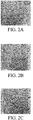
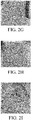
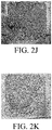
- the thermal-dissociation process was performed on the solar cell modules having the thermoplastic resin layer and the thermosetting resin layer with different thicknesses and to observe whether the solar cells were broken.
- the solar cell modules were baked to observe whether the solar cell modules could be disassembled successfully or broken pieces were caused.
- the following 11 groups of solar cell modules were tested. The test results are shown in FIGS. 2A to 2K .
- the composition materials and film thickness of the packaging films of the 11 groups of solar cell modules are as follows:
- the present disclosure provides a composite packaging film composed of a thermosetting resin layer (such as EVA) and a thermoplastic resin layer (such as SEBS).
- a thermosetting resin layer such as EVA
- a thermoplastic resin layer such as SEBS
- the molten packaging film can be separated from the glass and the complete battery at an appropriate temperature, which is beneficial to the subsequent high-value recycling.
Landscapes
- Photovoltaic Devices (AREA)
Abstract
Description
- The present disclosure relates to a solar cell module, and more particularly to a disassemblable and recyclable solar cell module.
- With the recent growth in the popularity of solar cell modules, an increasing number of waste solar cell modules are being generated, causing problems with respect to recycling and resource reuse. In order to recover materials from used solar cell modules, the solar cell modules must first be disassembled.
- In order to extend the service life of conventional silicon solar module structures, thermosetting polymers such as ethylene vinyl acetate (EVA) or polyolefin (PO) are generally used as packaging materials, to encapsulate and fix polycrystalline or monocrystalline solar cells. Once a cross-linking network occurs among molecules of the thermosetting polymers, neither the glass nor the solar cell panel can be separated by heating and melting the packaging film. As a result, an intact glass or a complete cell panel cannot be got and reused. Therefore, the current conventional method is to smash the module into pieces and burn it, to degrade the packaging film at a high enough temperature to separate the glass from the cell module. One of the difficulties encountered when disassembling conventional silicon solar cell modules is how to remove the thermosetting plastic material so that the glass and the cells can be taken out, recycled, and reused without damaging them.
- At present, there are two methods for removing thermosetting plastics. One is to decompose EVA in an acid solution or an organic solvent, and the other is to heat the silicon solar cell module at a temperature of 300°C to 550°C to separate the glass plate from the solar cell module. Either method is time-consuming and labor-intensive, and will cause secondary pollution. Therefore, there is an urgent need to solve the above problems by proposing a solar cell module that is easy to be disassembled and that can pass the IEC61215 electrical verification specification to achieve high-value recycling of waste modules in the industry.
- Therefore, the development of a disassemblable and recyclable solar cell module with efficiency is desirable.
- In accordance with one embodiment of the present disclosure, a solar cell module is provided. The solar cell module includes a first substrate; a second substrate opposite to the first substrate; a cell unit disposed between the first and the second substrates; a first thermosetting resin layer disposed between the cell unit and the first substrate; a first thermoplastic resin layer disposed between the cell unit and the first thermosetting resin layer; a second thermosetting resin layer disposed between the cell unit and the second substrate; and a second thermoplastic resin layer disposed between the cell unit and the second thermosetting resin layer.
- A detailed description is given in the following embodiments with reference to the accompanying drawings.
-
-
FIG. 1 shows a cross-sectional view of a solar cell module in accordance with one embodiment of the present disclosure; and -
FIGS. 2A to 2K show the results of disassemblable tests of solar cell modules in accordance with one embodiment of the present disclosure. - Referring to
FIG. 1 , in accordance with one embodiment of the present disclosure, asolar cell module 10 is provided.FIG. 1 shows a cross-sectional view of thesolar cell module 10. - In
FIG. 1 , thesolar cell module 10 includes afirst substrate 12, asecond substrate 14, acell unit 16, a firstthermosetting resin layer 18, a firstthermoplastic resin layer 20, a secondthermosetting resin layer 22 and a secondthermoplastic resin layer 24. Thesecond substrate 14 is opposite to thefirst substrate 12. Thecell unit 16 is disposed between thefirst substrate 12 and thesecond substrate 14. The firstthermosetting resin layer 18 is disposed between thecell unit 16 and thefirst substrate 12. The firstthermoplastic resin layer 20 is disposed between thecell unit 16 and the firstthermosetting resin layer 18. The secondthermosetting resin layer 22 is disposed between thecell unit 16 and thesecond substrate 14. The secondthermoplastic resin layer 24 is disposed between thecell unit 16 and the secondthermosetting resin layer 22. That is, in the disclosedsolar cell module 10, the two sides of thecell unit 16 are in contact with the firstthermoplastic resin layer 20 and the secondthermoplastic resin layer 24, respectively. One side of the firstthermosetting resin layer 18 is in contact with the firstthermoplastic resin layer 20, and the other side of the firstthermosetting resin layer 18 is in contact with thefirst substrate 12. One side of the secondthermosetting resin layer 22 is in contact with the secondthermoplastic resin layer 24, and the other side of the secondthermosetting resin layer 22 is in contact with thesecond substrate 14. - In some embodiments, the
first substrate 12 and thesecond substrate 14 may include glass, polyolefin resin or polyester resin, for example, polyethylene (PE), polypropylene (PP) or polyethylene terephthalate (PET). - In some embodiments, the first
thermosetting resin layer 18 and the secondthermosetting resin layer 22 may include an ethylene vinyl acetate (EVA) copolymer or polyolefin (PO). In some embodiments, when the firstthermosetting resin layer 18 and the secondthermosetting resin layer 22 include an ethylene vinyl acetate (EVA) copolymer, the weight ratio of vinyl acetate (VA) in the ethylene vinyl acetate (EVA) copolymer is in a range from about 25wt% to about 35wt%. In some embodiments, the thickness T1b of the firstthermosetting resin layer 18 and the thickness T2b of the secondthermosetting resin layer 22 are in a range from about 300µm to about 2,000µm. In some embodiments, the firstthermosetting resin layer 18 and the secondthermosetting resin layer 22 further include additives such as a hardening initiator, an antioxidant, a crosslinking agent, or a stabilizer. In some embodiments, the weight ratio of the additives in the firstthermosetting resin layer 18 and the secondthermosetting resin layer 22 is in a range from about 1wt% to about 5wt%. - In some embodiments, the first
thermoplastic resin layer 20 and the secondthermoplastic resin layer 24 may include diblock hydrogenated styrene-based resin or triblock hydrogenated styrene-based resin. In some embodiments, the firstthermoplastic resin layer 20 and the secondthermoplastic resin layer 24 may include, but are not limited to, the following copolymers, for example, hydrogenated (styrene-isoprene) diblock copolymers, hydrogenated (styrene-isoprene-styrene) triblock copolymers, hydrogenated (styrene-butadiene-styrene) triblock copolymers, hydrogenated (styrene-isoprene/butadiene-styrene) triblock copolymers, hydrogenated (styrene-ethylene branched isoprene) diblock copolymers, or a combination thereof. In some embodiments, the weight ratio of the styrene block in the diblock hydrogenated styrene-based resin or the triblock hydrogenated styrene-based resin is in a range from about 10wt% to about 35wt%. - In some embodiments, the first
thermoplastic resin layer 20 and the secondthermoplastic resin layer 24 may include diblock acrylic-based resin or triblock acrylic-based resin. In some embodiments, the firstthermoplastic resin layer 20 and the secondthermoplastic resin layer 24 may include, but are not limited to, the following copolymers, for example, poly(methylmethacrylate-b-isoprene), poly(methylmethacrylate-b-butadiene), poly(methylmethacrylate-b-isoprene-b-methylmethacrylate), poly(methylmethacrylate-b-butadiene-b-methylmethacrylate), poly(methylmethacrylate-b-isoprene/butadiene-b-methylmethacrylate), poly(methylmethacrylate/acrylate/methylmethacrylate), or a combination thereof. In some embodiments, the weight ratio of the methylmethacrylate (MMA) block in the diblock acrylic-based resin or the triblock acrylic-based resin is in a range from about 20wt% to about 60wt%. In some embodiments, the weight ratio of the methylmethacrylate (MMA) block in the diblock acrylic-based resin or the triblock acrylic-based resin is in a range from about 30wt% to about 50wt%. - In some embodiments, at least one of the first
thermoplastic resin layer 20 and the secondthermoplastic resin layer 24 contains 0.1% to 10% of diffusion particles. That is, one of the firstthermoplastic resin layer 20 and the secondthermoplastic resin layer 24 contains 0.1% to 10% of the diffusion particles, or both of the firstthermoplastic resin layer 20 and the secondthermoplastic resin layer 24 contain 0.1% to 10% of the diffusion particles. In some embodiments, the diffusion particles may include polyacrylic resin or copolymers derived therefrom, for example, methyl polyacrylate. In some embodiments, the diffusion particles may be spherical, with a particle size ranging from about 3µm to about 60µm, and a refractive index ranging from about 1.45 to about 1.57. The disclosed diffusion particles can be uniformly dispersed in the thermoplastic resin layer. Specifically, the diffusion particles are usually added to the thermoplastic resin layer located at a light-incident surface of the module. For example, if thesolar cell module 10 is a solar cell module that receives light by one side, the diffusion particles can be added to the firstthermoplastic resin layer 20 or the secondthermoplastic resin layer 24 located at the light-incident surface. However, if thesolar cell module 10 is a solar cell module that receives light by both sides, the diffusion particles can be added to the firstthermoplastic resin layer 20 and the secondthermoplastic resin layer 24 located at the light-incident surfaces at the same time. - In some embodiments, at least one of the first
thermoplastic resin layer 20 and the secondthermoplastic resin layer 24 contains 0.1% to 5% of fluorescent material. That is, one of the firstthermoplastic resin layer 20 and the secondthermoplastic resin layer 24 contains 0.1% to 5% of the fluorescent material, or both of the firstthermoplastic resin layer 20 and the secondthermoplastic resin layer 24 contains 0.1% to 5% of the fluorescent material. In some embodiments, the fluorescent material have the material properties of absorbing ultraviolet light and converting the ultraviolet light into visible light. In some embodiments, the melting point of the fluorescent material is between about 10°C to about 130°C. The disclosed fluorescent material can be uniformly dispersed in the thermoplastic resin layer. In some embodiments, the fluorescent material may include pyrene, naphthalene-imide, perylene-imide, carbazole or anthracene. Similarly, the fluorescent material is usually added to the thermoplastic resin layer located at a light-incident surface of the module. For example, if thesolar cell module 10 is a solar cell module that receives light by one side, the fluorescent material can be added to the firstthermoplastic resin layer 20 or the secondthermoplastic resin layer 24 located at the light-incident surface. However, if thesolar cell module 10 is a solar cell module that receives light by both sides, the fluorescent material can be added to the firstthermoplastic resin layer 20 and the secondthermoplastic resin layer 24 located at the light-incident surfaces at the same time. The disclosed fluorescent material can absorb an external ultraviolet light and convert the absorbed ultraviolet light into a visible light that can be used by the battery. On the one hand, it can protect the packaging material from ultraviolet light. On the other hand, it can also increase the light absorption of the battery. In addition, the disclosed fluorescent material is an organic fluorescent material, which can be added to the resin layer to obtain a good dispersion effect without increasing the haze, maintaining the transparency of the packaging material. - In some embodiments, if the
solar cell module 10 is a solar cell module that receives light by one side, the firstthermosetting resin layer 18 or the secondthermosetting resin layer 22 located at the light-incident surface of the module may contain 0.1% to 10% of the diffusion particles. In some embodiments, if thesolar cell module 10 is a solar cell module that receives light by both sides, the firstthermosetting resin layer 18 and the secondthermosetting resin layer 22 located at the light-incident surfaces of the module may contain 0.1% to 10% of the diffusion particles at the same time. In some embodiments, the diffusion particles can be uniformly dispersed in the thermosetting resin layer. - In some embodiments, if the
solar cell module 10 is a solar cell module that receives light by one side, the firstthermosetting resin layer 18 or the secondthermosetting resin layer 22 located at the light-incident surface of the module may contain 0.1% to 5% of the fluorescent material. In some embodiments, if thesolar cell module 10 is a solar cell module that receives light by both sides, the firstthermosetting resin layer 18 and the secondthermosetting resin layer 22 located at the light-incident surfaces of the module may contain 0.1% to 5% of the fluorescent material at the same time. In some embodiments, the fluorescent material can be uniformly dispersed in the thermosetting resin layer. - In some embodiments, the total thickness T1 of the first
thermosetting resin layer 18 and the firstthermoplastic resin layer 20 is in a range from about 0.3mm to about 2.0mm. In some embodiments, the ratio of the thickness T1a of the firstthermoplastic resin layer 20 and the thickness T1b of the firstthermosetting resin layer 18 is in a range from about 1:0.59 to about 1:10. In some embodiments, the ratio of the thickness T1a of the firstthermoplastic resin layer 20 and the thickness T1b of the firstthermosetting resin layer 18 is in a range from about 1:1 to about 1:2. In some embodiments, the total thickness T2 of the secondthermosetting resin layer 22 and the secondthermoplastic resin layer 24 is in a range from about 0.3mm to about 2.0mm. In some embodiments, the ratio of the thickness T2a of the secondthermoplastic resin layer 24 and the thickness T2b of the secondthermosetting resin layer 22 is in a range from about 1:0.59 to about 1:10. In some embodiments, the ratio of the thickness T2a of the secondthermoplastic resin layer 24 and the thickness T2b of the secondthermosetting resin layer 22 is in a range from about 1:1 to about 1:2. - In some embodiments, the glass transition temperature of the first
thermoplastic resin layer 20 and the secondthermoplastic resin layer 24 is in a range from about 15°C to about -20°C. In some embodiments, the glass transition temperature of the firstthermoplastic resin layer 20 and the secondthermoplastic resin layer 24 is in a range from about 10°C to about -50°C. In some embodiments, the melt flow index of the firstthermoplastic resin layer 20 and the secondthermoplastic resin layer 24 is in a range from about 1.0 to about 31.0. In some embodiments, the melt flow index of the firstthermoplastic resin layer 20 and the secondthermoplastic resin layer 24 is in a range from about 1.0 to about 8.0. In some embodiments, the hardness (type A) of the firstthermoplastic resin layer 20 and the secondthermoplastic resin layer 24 is in a range from about 30 to about 90. In some embodiments, the hardness (type A) of the firstthermoplastic resin layer 20 and the secondthermoplastic resin layer 24 is in a range from about 35 to about 80. - In the present disclosure, the first
thermosetting resin layer 18 and the firstthermoplastic resin layer 20 form a transparent composite packaging film by, for example, bonding or co-extrusion. The secondthermosetting resin layer 22 and the secondthermoplastic resin layer 24 form another transparent composite packaging film by, for example, bonding or co-extrusion. - Specifically, after the disclosed
solar cell module 10 is tested for weather resistance, thesolar cell module 10 is further disassembled by, for example, a thermal dissociation method or a chemical dissociation method. In some embodiments, in the thermal dissociation method, thesolar cell module 10 is disassembled by baking at a temperature of 450°C. In some embodiments, in the chemical dissociation method, thesolar cell module 10 is disassembled by soaking in a solvent at a temperature below 40°C. In some embodiments, the solvent used in the chemical dissociation method may include hydrocarbon solvents such as toluene, 2-toluene, hexane, or cyclohexane. - In the disclosed solar cell module, the thermoplastic resin layer is added between the cell unit and the conventional thermosetting packaging material layer, and its material may include diblock or triblock hydrogenated styrene-based resin, or diblock or triblock acrylic-based resin. The structural design will enable the cell module to have characteristics of high light transmittance, low water absorption, high insulation and weather resistance, and resistance to PID, humidity, heat, and UV, so to meet the needs of cell modules. Also, the cell modules can be easily disassembled and recycled by simple thermal dissociation method or chemical dissociation method, which is not easy to cause fragments, and has the advantage of easy disassembly.
- In the disclosed solar cell module, adding a specific content (for example, 0.1% to 10%) of the diffusion particles to the thermoplastic resin layer can improve the diffusion effect of light in the cell (a diffusion factor of 27 or more). The scattering characteristics can improve the light utilization rate of the battery. Even with the addition of the diffusion particles, the disclosed solar cell module still has optical properties with high light transmittance.
- In the present disclosure, in addition to adding a specific content of the diffusion particles to the thermoplastic resin layer, a specific content (such as 0.1% to 5%) of the fluorescent material can also be added to the thermoplastic resin layer at the same time. In addition to the diffusion particles that can guide the reflected light of the battery back into the battery, the fluorescent material can also absorb external ultraviolet light and convert it into visible light that the battery can use, increasing the amount of light received by the battery. Therefore, when comparing the power gain of the cell module before and after packaging with the conventional cell module, the disclosed solar cell module can obtain a better power gain.
- Preparation Example 1
- 100kg of triblock acrylic-based resin (KURARAY, LA2140, melt flow index: 31g/10min (190 °C, 2.16kgf)) and 3kg of diffusion particles (purchased from Soken Chemical & Engineering Co., Ltd., material: polyacrylic resin, particle size: 10µm, refractive index: 1.49) were granulated by a single screw mixer (Japan MEISEI KINZOKU MFG. CO., LTD., model: FRP-V32C). The temperature of the single screw mixer was divided into four stages, namely 145°C, 150°C, 150°C and 145°C. After a press machine (GANG LING MACHINERY CO., LTD., model: HP-50) was preheated at 150°C for 10 minutes, the sample was compressed at 150°C for 10 minutes (pressure: 100kg/cm2) to form a film as a light diffusion composite film.
- 100kg of triblock acrylic-based resin (KURARAY, LA2140, melt flow index: 31g/10min (190°C, 2.16kgf)), 3kg of diffusion particles (purchased from Soken Chemical & Engineering Co., Ltd., material: polyacrylic resin, particle size: 10µm, refractive index: 1.49) and 0.1kg of carbazole fluorescent material (purchased from NISSOKU TECHNO FINE CHEMICAL CO., LTD.) were granulated by a single screw mixer (Japan MEISEI KINZOKU MFG. CO., LTD., model: FRP-V32C). The temperature of the single screw mixer was divided into four stages, namely 145°C, 150°C, 150°C and 145°C. After a press machine (GANG LING MACHINERY CO., LTD., model: HP-50) was preheated at 150°C for 10 minutes, the sample was compressed at 150°C for 10 minutes (pressure: 100kg/cm2) to form a thermoplastic film as a light diffusion fluorescent composite film.
- In this example, the physical property tests were performed on the
solar cell module 10 as shown inFIG. 1 . In the module structure, the materials and dimensions of related components are described below: The first substrate (back plate) 12 was a solar back plate with a thickness of about 0.31mm. The second substrate (front plate) 14 was transparent glass with a thickness of about 3.2mm. The thickness of thecell unit 16 was about 180µm. The firstthermosetting resin layer 18 was an ethylene vinyl acetate (EVA) copolymer (SKC, EF2N) with a thickness of about 400µm. The firstthermoplastic resin layer 20 was a hydrogenated (styrene-butadiene-styrene) triblock copolymer (SEBS) (purchased from Asahi chemical Co. Ltd. S.O.E.™ S1611; glass transition temperature: 9°C; melt flow index: 4g/10min (190°C; 2.16kgf)) with a thickness of about 292µm. The secondthermosetting resin layer 22 was an ethylene vinyl acetate (EVA) copolymer (SKC, EF2N) with a thickness of about 400µm. The secondthermoplastic resin layer 24 was a hydrogenated (styrene-butadiene-styrene) triblock copolymer (SEBS) (purchased from Asahi chemical Co. Ltd. S.O.E.™ S1611; glass transition temperature: 9°C; melt flow index: 4g/10min (190°C; 2.16kgf)) with a thickness of about 292µm. The total thickness T1 of the firstthermosetting resin layer 18 and the firstthermoplastic resin layer 20 was approximately 692±3µm. The total thickness T2 of the secondthermosetting resin layer 22 and the secondthermoplastic resin layer 24 was approximately 692±3µm. The following physical property tests were performed on thesolar cell module 10, including, total light transmittance (%), haze (%), yellowness index (YI), water vapor transmission rate (WVTR) (g/m2-day), tensile strength at break (MPa), peeling strength (N) and volume resistance (VR) (Ω. cm), and the test results are shown in Table 1. - In this example, the physical property tests were performed on the
solar cell module 10 as shown inFIG. 1 . In the module structure, the materials and dimensions of related components are described below: The first substrate (back plate) 12 was a solar back plate with a thickness of about 0.31mm. The second substrate (front plate) 14 was transparent glass with a thickness of about 3.2mm. The thickness of thecell unit 16 was about 180µm. The firstthermosetting resin layer 18 was an ethylene vinyl acetate (EVA) copolymer (SKC, EF2N) with a thickness of about 400µm. The firstthermoplastic resin layer 20 was a hydrogenated (styrene-butadiene-styrene) triblock copolymer (SEBS) (purchased from Asahi chemical Co. Ltd. S.O.E.™ S1611; glass transition temperature: 9°C; melt flow index: 4g/10min (190°C; 2.16kgf)) with a thickness of about 511µm. The secondthermosetting resin layer 22 was an ethylene vinyl acetate (EVA) copolymer (SKC, EF2N) with a thickness of about 400µm. The secondthermoplastic resin layer 24 was a hydrogenated (styrene-butadiene-styrene) triblock copolymer (SEBS) (purchased from Asahi chemical Co. Ltd. S.O.E.™ S1611; glass transition temperature: 9°C; melt flow index: 4g/10min (190°C; 2.16kgf)) with a thickness of about 511µm. The total thickness T1 of the firstthermosetting resin layer 18 and the firstthermoplastic resin layer 20 was approximately 911±3µm. The total thickness T2 of the secondthermosetting resin layer 22 and the secondthermoplastic resin layer 24 was approximately 911±3µm. The following physical property tests were performed on thesolar cell module 10, including, total light transmittance (%), haze (%), yellowness index (YI), water vapor transmission rate (WVTR) (g/m2-day), tensile strength at break (MPa), peeling strength (N) and volume resistance (VR) (Ω. cm), and the test results are shown in Table 1. - In this example, the physical property tests were performed on the
solar cell module 10 as shown inFIG. 1 . In the module structure, the materials and dimensions of related components are described below: The first substrate (back plate) 12 was a solar back plate with a thickness of about 0.31mm. The second substrate (front plate) 14 was transparent glass with a thickness of about 3.2mm. The thickness of thecell unit 16 was about 180µm. The firstthermosetting resin layer 18 was an ethylene vinyl acetate (EVA) copolymer (SKC, EF2N) with a thickness of about 400µm. The firstthermoplastic resin layer 20 was a triblock acrylic-based resin (LA2140; purchased from KURARAY Co. Ltd.; melt flow index: 31g/10min (190°C; 2.16kgf)) with a thickness of about 320µm. The secondthermosetting resin layer 22 was an ethylene vinyl acetate (EVA) copolymer (SKC, EF2N) with a thickness of about 400µm. The secondthermoplastic resin layer 24 was a triblock acrylic-based resin (LA2140; purchased from KURARAY Co. Ltd.; melt flow index: 31g/10min (190°C; 2.16kgf)) with a thickness of about 320µm. The total thickness T1 of the firstthermosetting resin layer 18 and the firstthermoplastic resin layer 20 was approximately 720µm. The total thickness T2 of the secondthermosetting resin layer 22 and the secondthermoplastic resin layer 24 was approximately 720µm. The following physical property tests were performed on thesolar cell module 10, including, total light transmittance (%), haze (%), yellowness index (YI), water vapor transmission rate (WVTR) (g/m2-day), tensile strength at break (MPa), peeling strength (N) and volume resistance (VR) (Ω. cm), and the test results are shown in Table 1. - In this comparative example, the physical property tests were performed on the specific solar cell module (the thermosetting resin layer was in contact with the cell unit and the substrate simultaneously). In the module structure, the materials and dimensions of related components are described below: The first substrate (back plate) was a solar back plate with a thickness of about 0.31mm. The second substrate (front plate) was transparent glass with a thickness of about 3.2mm. The thickness of the cell unit was about 180µm. The first thermosetting resin layer was an ethylene vinyl acetate (EVA) copolymer (SKC, EF2N) with a thickness of about 400µm. The second thermosetting resin layer was an ethylene vinyl acetate (EVA) copolymer (SKC, EF2N) with a thickness of about 400µm. The following physical property tests were performed on the solar cell module, including, total light transmittance (%), haze (%), yellowness index (YI), water vapor transmission rate (WVTR) (g/m2-day), tensile strength at break (MPa), peeling strength (N) and volume resistance (VR) (Ω. cm), and the test results are shown in Table 1.
- In this comparative example, the physical property tests were performed on the specific solar cell module (the thermosetting resin layer was in contact with the cell unit and the substrate simultaneously). In the module structure, the materials and dimensions of related components are described below: The first substrate (back plate) was a solar back plate with a thickness of about 0.31mm. The second substrate (front plate) was transparent glass with a thickness of about 3.2mm. The thickness of the cell unit was about 180µm. The first thermosetting resin layer was polyolefin (PO) (TF4; purchased from HANGZHOU FIRST APPLIED MATERIAL CO. LTD.) with a thickness of about 400µm. The second thermosetting resin layer was polyolefin (PO) (TF4; purchased from HANGZHOU FIRST APPLIED MATERIAL CO. LTD.) with a thickness of about 400µm. The following physical property tests were performed on the solar cell module, including, total light transmittance (%), haze (%), yellowness index (YI), water vapor transmission rate (WVTR) (g/m2-day), tensile strength at break (MPa), peeling strength (N) and volume resistance (VR) (Ω. cm), and the test results are shown in Table 1.
- In this comparative example, the physical property tests were performed on the specific solar cell module (the thermoplastic resin layer was in contact with the cell unit and the substrate simultaneously). In the module structure, the materials and dimensions of related components are described below: The first substrate (back plate) was a solar back plate with a thickness of about 0.31mm. The second substrate (front plate) was transparent glass with a thickness of about 3.2mm. The thickness of the cell unit was about 180µm. The first thermoplastic resin layer was a hydrogenated (styrene-butadiene-styrene) triblock copolymer (SEBS) (purchased from Asahi chemical Co. Ltd. S.O.E.™ S1611; glass transition temperature: 9°C; melt flow index: 4g/10min (190°C; 2.16kgf)) with a thickness of about 424µm. The second thermoplastic resin layer was a hydrogenated (styrene-butadiene-styrene) triblock copolymer (SEBS) (purchased from Asahi chemical Co. Ltd. S.O.E.™ S1611; glass transition temperature: 9°C; melt flow index: 4g/10min (190°C; 2.16kgf)) with a thickness of about 424µm. The following physical property tests were performed on the solar cell module, including, total light transmittance (%), haze (%), yellowness index (YI), water vapor transmission rate (WVTR) (g/m2-day), tensile strength at break (MPa), peeling strength (N) and volume resistance (VR) (Ω. cm), and the test results are shown in Table 1.
- In this comparative example, the physical property tests were performed on the specific solar cell module (the mixed resin layer of EVA and SEBS was in contact with the cell unit and the substrate simultaneously). In the module structure, the materials and dimensions of related components are described below: The first substrate (back plate) was a solar back plate with a thickness of about 0.31mm. The second substrate (front plate) was transparent glass with a thickness of about 3.2mm. The thickness of the cell unit was about 180µm. The first resin layer was a mixed layer of an ethylene vinyl acetate (EVA) copolymer (KA40; purchased from The Polyolefin Company) and a hydrogenated (styrene-butadiene-styrene) triblock copolymer (SEBS) (purchased from Asahi chemical Co. Ltd. S.O.E.™ S1611; glass transition temperature: 9°C; melt flow index: 4g/10min (190°C; 2.16kgf)) with a thickness of about 400µm. The second resin layer was a mixed layer of an ethylene vinyl acetate (EVA) copolymer (KA40; purchased from The Polyolefin Company) and a hydrogenated (styrene-butadiene-styrene) triblock copolymer (SEBS) (purchased from Asahi chemical Co. Ltd. S.O.E.™ S1611; glass transition temperature: 9°C; melt flow index: 4g/10min (190°C; 2.16kgf)) with a thickness of about 400µm. The following physical property tests were performed on the solar cell module, including, total light transmittance (%), haze (%), yellowness index (YI), water vapor transmission rate (WVTR) (g/m2-day), tensile strength at break (MPa), peeling strength (N) and volume resistance (VR) (Ω. cm), and the test results are shown in Table 1.
Table 1 Example 1 Example 2 Example 3 Com. Example 1 Com. Example 2 Com. Example 3 Com. Example 4 Packaging materials EVA/ SEBS EVA/ SEBS EVA/ Acrylic-based resin Thermosetting EVA Thermosetting PO Thermoplastic SEBS EVA and SEBS hybrid Thickness (T1) (µm) 692±3 911±3 720 400 400 424 400 Total light transmittance (%) 87.6 87.4 87.84 88.4 88.9 88.3 54.97 Haze (%) 3.89 4.32 2.68 0.929 5.39 1.85 99.5 Yellowness index -0.01 0.1 0.02 0.11 0.14 0.32 14.65 Water vapor 5.01 3.61 2.60 34.00 3.30 1.55 10.12 transmission rate (g/m2-day) Tensile strength at break (MPa) 13.59 18.63 10.44 19 4.96 20.21 11.4 Peeling strength (N) 97.22 97.90 118.7 124.9 101 7.01 10.52 Volume resistance (Ω. cm) 5.63E +14 1.12E +15 4.99E +13 1.72E +14 8.65E +15 8.90E +15 2.29E +15 Cell panel intact status during thermal-degradation process at 450°C intact intact intact cracks cracks intact intact - From the test results in Table 1, it can be seen that, in the disclosed solar cell modules (Examples 1-3), regardless of whether the material of the thermoplastic resin layer in the composite packaging material was hydrogenated styrene-based resin (such as SEBS) or acrylic block copolymer resin (such as acrylic block copolymer), according to the measured haze, water vapor transmission rate, and volume resistance, all of them met the requirements for the module structure to have high light transmission, low water absorption and high insulation and weather resistance.
- In addition, when the thickness ratio of the thermoplastic resin layer and the thermosetting resin layer was between 1:0.59 and 1:10, the cell panel was not broken during the thermal-degradation process (Examples 1-3). When the thermal-degradation process was performed at 450°C in comparative Examples 1 and 2, where the modules have only the thermosetting packaging film, the provided solar cell modules cracked after testing. In Comparative Example 3, where the module was packaged by the thermoplastic SEBS, the subsequent electrical PID tests of the module cannot pass the standard that power loss needs to be less than 5% due to poor adhesion to glass. Comparative Example 4 also shows that when the packaging film was made from two mixed resins, its light transmittance was only 54.97%, which does not meet the standard that the light transmittance of the packaging film needs to be greater than 85%. Obviously, it cannot be made into a packaging film and to be compared with the examples. However, in the disclosed solar cell modules (Examples 1-3), regardless of whether the material of the thermoplastic resin layer in the composite packaging material was hydrogenated styrene-based resin (such as SEBS) or acrylic block copolymer resin (such as acrylic block copolymer), in the process of disassembling through the thermal dissociation method, they can be disassembled successfully without cracks or not broken, which proves that the disclosed module structures had the advantage of being easy disassembled.
- In this example, the physical property tests were performed on the
solar cell module 10 as shown inFIG. 1 . In the module structure, the materials and dimensions of related components are described below: The first substrate (back plate) 12 was a solar back plate with a thickness of about 0.31mm. The second substrate (front plate) 14 was transparent glass with a thickness of about 3.2mm. The thickness of thecell unit 16 was about 180µm. The firstthermosetting resin layer 18 was an ethylene vinyl acetate (EVA) copolymer (SKC, EF2N) with a thickness of about 400µm. The firstthermoplastic resin layer 20 with a thickness of about 292µm included triblock acrylic-based resin (KURARAY, LA2140, melt flow index: 31g/10min (190°C, 2.16kgf)) and 3% of spherical diffusion particles (purchased from Soken Chemical & Engineering Co., Ltd., material: polyacrylic resin, particle size: 10µm, refractive index: 1.49). The secondthermosetting resin layer 22 was an ethylene vinyl acetate (EVA) copolymer (SKC, EF2N) with a thickness of about 400µm. The secondthermoplastic resin layer 24 with a thickness of about 292µm included triblock acrylic-based resin (KURARAY, LA2140, melt flow index: 31g/10min (190°C, 2.16kgf)) and 3% of spherical diffusion particles (purchased from Soken Chemical & Engineering Co., Ltd., material: polyacrylic resin, particle size: 10µm, refractive index: 1.49). The total thickness T1 of the firstthermosetting resin layer 18 and the firstthermoplastic resin layer 20 was approximately 692±3µm. The total thickness T2 of the secondthermosetting resin layer 22 and the secondthermoplastic resin layer 24 was approximately 692±3µm. The following physical property tests were performed on thesolar cell module 10, including haze (%), total light transmittance (%) and diffusion factor, and the test results are shown in Table 2. In addition, thesolar cell module 10 was tested for power gain (%) before and after packaging. The test results are shown in Table 3 below. The measurement method of light transmittance was ASTM D1003. The measurement method of haze was ASTM D1003. The measurement method of maximum power was IEC60891. The measurement method of short-circuit current was IEC60891. The measurement method of open-circuit voltage was IEC60891. - In this example, the physical property tests were performed on the
solar cell module 10 as shown inFIG. 1 . In the module structure, the materials and dimensions of related components are described below: The first substrate (back plate) 12 was a solar back plate with a thickness of about 0.31mm. The second substrate (front plate) 14 was transparent glass with a thickness of about 3.2mm. The thickness of thecell unit 16 was about 180µm. The firstthermosetting resin layer 18 was an ethylene vinyl acetate (EVA) copolymer (SKC, EF2N) with a thickness of about 400µm. The firstthermoplastic resin layer 20 with a thickness of about 292µm included triblock acrylic-based resin (KURARAY, LA2140, melt flow index: 31g/10min (190°C, 2.16kgf)), 3% of spherical diffusion particles (purchased from Soken Chemical & Engineering Co., Ltd., material: polyacrylic resin, particle size: 10µm, refractive index: 1.49) and 0.1% of carbazole fluorescent material (purchased from NISSOKU TECHNO FINE CHEMICAL CO., LTD., melting point: 80°C). The secondthermosetting resin layer 22 was an ethylene vinyl acetate (EVA) copolymer (SKC, EF2N) with a thickness of about 400µm. The secondthermoplastic resin layer 24 with a thickness of about 292µm included triblock acrylic-based resin (KURARAY, LA2140, melt flow index: 31g/10min (190°C, 2.16kgf)), 3% of spherical diffusion particles (purchased from Soken Chemical & Engineering Co., Ltd., material: polyacrylic resin, particle size: 10µm, refractive index: 1.49) and 0.1% of carbazole fluorescent material (purchased from NISSOKU TECHNO FINE CHEMICAL CO., LTD., melting point: 80°C). The total thickness T1 of the firstthermosetting resin layer 18 and the firstthermoplastic resin layer 20 was approximately 692±3µm. The total thickness T2 of the secondthermosetting resin layer 22 and the secondthermoplastic resin layer 24 was approximately 692±3µm. The following physical property tests were performed on thesolar cell module 10, including haze (%), total light transmittance (%) and diffusion factor, and the test results are shown in Table 2. In addition, thesolar cell module 10 was tested for power gain (%) before and after packaging. The test results are shown in Table 3 below. - In this comparative example, the physical property tests were performed on the
solar cell module 10 as shown inFIG. 1 . In the module structure, the materials and dimensions of related components are described below: The first substrate (back plate) 12 was a solar back plate with a thickness of about 0.31mm. The second substrate (front plate) 14 was transparent glass with a thickness of about 3.2mm. The thickness of thecell unit 16 was about 180µm. The firstthermosetting resin layer 18 was an ethylene vinyl acetate (EVA) copolymer (SKC, EF2N) with a thickness of about 400µm. The firstthermoplastic resin layer 20 with a thickness of about 292µm included triblock acrylic-based resin (KURARAY, LA2140, melt flow index: 31g/10min (190 °C, 2.16kgf)). The secondthermosetting resin layer 22 was an ethylene vinyl acetate (EVA) copolymer (SKC, EF2N) with a thickness of about 400µm. The secondthermoplastic resin layer 24 with a thickness of about 292µm included triblock acrylic-based resin (KURARAY, LA2140, melt flow index: 31g/10min (190°C, 2.16kgf)). The total thickness T1 of the firstthermosetting resin layer 18 and the firstthermoplastic resin layer 20 was approximately 692±3µm. The total thickness T2 of the secondthermosetting resin layer 22 and the secondthermoplastic resin layer 24 was approximately 692±3µm. The following physical property tests were performed on thesolar cell module 10, including haze (%), total light transmittance (%) and diffusion factor, and the test results are shown in Table 2. In addition, thesolar cell module 10 was tested for power gain (%) before and after packaging. The test results are shown in Table 3 below. - In this comparative example, the physical property tests were performed on the specific solar cell module (the thermosetting resin layer was in contact with the cell unit and the substrate simultaneously). In the module structure, the materials and dimensions of related components are described below: The first substrate (back plate) was a solar back plate with a thickness of about 0.31mm. The second substrate (front plate) was transparent glass with a thickness of about 3.2mm. The thickness of the cell unit was about 180µm. The first thermosetting resin layer was an ethylene vinyl acetate (EVA) copolymer (SKC, EF2N) with a thickness of about 400µm. The second thermosetting resin layer was an ethylene vinyl acetate (EVA) copolymer (SKC, EF2N) with a thickness of about 400µm. The following physical property tests were performed on the
solar cell module 10, including haze (%), total light transmittance (%) and diffusion factor, and the test results are shown in Table 2. In addition, thesolar cell module 10 was tested for power gain (%) before and after packaging. The test results are shown in Table 3 below. - In this comparative example, the physical property tests were performed on the specific solar cell module (the thermosetting resin layer was in contact with the cell unit and the substrate simultaneously). In the module structure, the materials and dimensions of related components are described below: The first substrate (back plate) was a solar back plate with a thickness of about 0.31mm. The second substrate (front plate) was transparent glass with a thickness of about 3.2mm. The thickness of the cell unit (a light guide bar was pasted on the surface of the cell unit) was about 180µm. The first thermosetting resin layer was an ethylene vinyl acetate (EVA) copolymer (SKC, EF2N) with a thickness of about 400µm. The second thermosetting resin layer was an ethylene vinyl acetate (EVA) copolymer (SKC, EF2N) with a thickness of about 400µm. The following physical property tests were performed on the
solar cell module 10, including haze (%), total light transmittance (%) and diffusion factor, and the test results are shown in Table 2. In addition, thesolar cell module 10 was tested for power gain (%) before and after packaging. The test results are shown in Table 3 below. - In this comparative example, the physical property tests were performed on the specific solar cell module (the thermosetting resin layer was in contact with the cell unit and the substrate simultaneously). In the module structure, the materials and dimensions of related components are described below: The first substrate (back plate) was a solar back plate with a thickness of about 0.31mm. The second substrate (front plate) was transparent glass with a thickness of about 3.2mm. The thickness of the cell unit was about 180µm. The first thermosetting resin layer with a thickness of about 400µm included an ethylene vinyl acetate (EVA) copolymer (SKC, EF2N) and 3% of spherical diffusion particles (purchased from Soken Chemical & Engineering Co., Ltd., material: polyacrylic resin, particle size: 10µm, refractive index: 1.49). The second thermosetting resin layer with a thickness of about 400µm included an ethylene vinyl acetate (EVA) copolymer (SKC, EF2N) and 3% of spherical diffusion particles (purchased from Soken Chemical & Engineering Co., Ltd., material: polyacrylic resin, particle size: 10µm, refractive index: 1.49). The following physical property tests were performed on the
solar cell module 10, including haze (%), total light transmittance (%) and diffusion factor, and the test results are shown in Table 2. In addition, thesolar cell module 10 was tested for power gain (%) before and after packaging. The test results are shown in Table 3 below.Table 2 Example 4 Example 5 Com. Example 5 Com. Example 6 Com. Example 7 Com. Example 8 Module Composite film/ cell unit Composite film/ cell unit Composite film/ cell unit EVA film/ cell unit EVA film/ cell unit (with light guide bar) EVA film/ cell unit Composition of packaging film EVA thermosetting film/ triblock acrylic-based resin film/ diffusion particles EVA thermosetting film/ triblock acrylic-based resin film/ diffusion particles/ fluorescent material EVA thermosetting film/ triblock acrylic-based resin film EVA thermosetting film EVA thermosetting film EVA thermosetting film/ diffusion particles Haze (%) 28.8 28.5 1.9 1.4 1.4 12.56 Total light transmittance (%) 94.7 96.0 96.6 97.6 97.6 97.04 Diffusion factor 27.3 27.4 1.9 1.4 1.4 12.19 Table 3 Example 4 Example 5 Com. Example 5 Com. Example 6 Com. Example 7 Com. Example 8 Module Composite film/ cell unit Composite film/ cell unit Composite film/ cell unit EVA film/ cell unit EVA film/ cell unit (with light guide bar) EVA film/ cell unit Composition of packaging film EVA thermosetting film/ triblock acrylic-based resin film/ diffusion particles EVA thermosetting film/ triblock acrylic-based resin film/ diffusion particles/ fluorescent material EVA thermosetting film/ triblock acrylic-based resin film EVA thermosetting film EVA thermosetting film EVA thermosetting film/ diffusion particles Before packaging 12.359 11.933 12.167 13.035 12.525 13.024 After packaging 17.36 16.096 16.167 17.259 17.22 14.67 Power gain (%) 40.46 34.89 32.88 32.41 37.49 12.64 - From the test results in Table 2, it can be seen that, in the disclosed solar cell modules (such as Examples 4 and 5), the diffusion particles with the specific content were added to the thermoplastic resin layer. Therefore, the diffusion effect of light in the battery can be greatly improved indeed (the diffusion factor was as high as 27 or more). Also, according to the measured haze, total light transmittance and other data, the disclosed solar cell modules still have optical characteristics of high light transmittance.
- From the test results in Table 3, it can be seen that, in the disclosed solar cell modules, the diffusion particles with the specific content were added to the thermoplastic resin layer (such as Example 4). The diffusion particles and the fluorescent material with the specific contents respectively were added to the thermoplastic resin layer at the same time (such as Example 5). The diffusion particles can guide the reflected light of the battery back into the battery, and the fluorescent material can absorb external ultraviolet light and convert it into visible light that the battery can use, so that the amount of light received by the battery was increased. Therefore, when comparing the power gain of the cell modules before and after packaging with the cell modules provided by Comparative Examples 5-7, the disclosed solar cell modules can obtain a better power gain.
- In Comparative Example 4, since the light transmittance of the film prepared by directly blending two materials was only 54.97% as shown in Table 1, which was not enough to meet the requirement that the light transmittance of the solar packaging film needs to be greater than 85%, it is not necessary to perform the potential induced degradation (PID) tests as the solar cell modules provided in Examples 1-3 and Comparative Examples 1-3. That is, the degree of the power loss of each cell module was tested under the conditions of a temperature of 85°C, a relative humidity of 85%, and an input voltage of 1,000V, and the test results are shown in Table 4 below.
Table 4 Packaging materials Test time Isc Voc FF Impp Vmpp Pmpp Power loss (%) Example 1 EVA/ SEBS after packaging 9.842 2.665 75.27 9.213 2.143 19.741 96hr 9.736 2.666 75.47 9.102 2.152 19.591 0.76% 288hr 9.683 2.665 75.44 9.038 2.154 19.465 1.40% Example 2 EVA/ SEBS after packaging 9.816 2.660 75.25 9.198 2.136 19.648 96hr 9.677 2.662 75.36 9.068 2.141 19.410 1.21% 288hr 9.640 2.664 75.60 9.021 2.152 19.413 1.20% Example 3 EVA/ Acrylic-based resin after packaging 2.66 9.64 2.16 9.16 77.04 19.756 96hr 2.67 9.57 2.16 9.07 77.01 19.555 1.02% 288hr 2.66 9.53 2.15 9.01 76.37 19.359 2.01% Com. Example 1 Thermosetting EVA after packaging 9.814 2.652 74.66 9.137 2.127 19.431 96hr 9.700 2.653 74.28 9.001 2.123 19.113 1.64% 288hr 9.695 2.655 73.99 8.962 2.125 19.047 1.98% Com. Example 2 Thermosetting PO after packaging 8.977 2.544 71.089 8.274 1.962 16.232 96hr 8.961 2.539 70.852 8.287 1.946 16.123 0.672% 288hr 8.961 2.539 70.135 8.421 1.895 15.956 1.700% Com. Example 3 Thermoplastic SEBS after packaging 8.892 2.528 70.727 8.217 1.935 15.897 96hr 8.857 2.525 69.715 8.286 1.881 15.590 1.933 288hr 8.838 2.522 60.417 7.866 1.712 13.469 15.271 Com. Example 4 EVA and SEBS hybrid after packaging - - - - - - - 96hr - - - - - - - 288hr - - - - - - - - From the test results in Table 4, it can be seen that, in the disclosed solar cell modules (Examples 1-3), regardless of whether the material of the thermoplastic resin layer in the composite packaging material was hydrogenated styrene-based resin (such as SEBS) or acrylic block copolymer resin (such as acrylic block copolymer), according to the measured data of the power loss (after 96hr or 288hr), it has been proved that adding the thermoplastic resin layer will not reduce the efficiency of the solar module.
- The humidity-heat aging test was performed on the solar cell module provided in Example 1. That is, the degree of the power loss of the cell module was tested under the conditions of a temperature of 85°C, a relative humidity of 85%, and a period of 1,000hr, and the test results are shown in Table 5 below.
Table 5 The humidity -heat aging test Packaging materials Test time Voc _K (V) Isc _K (A) Vmp _K (V) Imp _K (A) Pmax _K (W) FF (%) ΔPmax (W) Power loss (%) EVA/ SEBS after packaging 0.633 9.098 0.505 8.607 4.345 75.425 -0.082 1.882 1,000hr 0.631 8.956 0.504 8.455 4.263 75.461 - From the test results in Table 5, it can be seen that, in the disclosed solar cell module (Example 1), when the material of the thermoplastic resin layer in the composite packaging material was hydrogenated styrene-based resin (such as SEBS), according to the measured data of the power loss (after 1,000hr), it has been proved that the module structure had the advantage of resisting aging caused by humidity and heat.
- The UV aging test was performed on the solar cell module provided in Example 1. That is, the degree of the power loss of the cell module was tested under the condition of a cumulative UV illumination of 15kWh/m2, and the test results are shown in Table 6 below.
Table 6 The UV aging test Packaging materials Test time Voc K (V) Isc K (A) Vmp K (V) Imp K (A) Pmax K (W) FF (%) ΔPma x (W) Power loss (%) EVA/ SEBS after packaging 0.635 9.050 0.510 8.483 4.328 75.341 -0.036 0.833 After irradiating UV of 15kWh/m2 0.634 8.982 0.509 8.424 4.292 75.320 - From the test results in Table 6, it can be seen that, in the disclosed solar cell module (Example 1), when the material of the thermoplastic resin layer in the composite packaging material was hydrogenated styrene-based resin (such as SEBS), according to the measured data of the power loss (After UV irradiation of 15kWh/m2), it has been proved that the module structure had the advantage of resisting aging caused by irradiating UV.
- In this example, the thermal-dissociation process was performed on the solar cell modules having the thermoplastic resin layer and the thermosetting resin layer with different thicknesses and to observe whether the solar cells were broken. At a temperature of 450°C, the solar cell modules were baked to observe whether the solar cell modules could be disassembled successfully or broken pieces were caused. The following 11 groups of solar cell modules were tested. The test results are shown in
FIGS. 2A to 2K . The composition materials and film thickness of the packaging films of the 11 groups of solar cell modules are as follows: - Group 1: the thickness of the thermoplastic SEBS was 220µm, the thickness of the thermosetting EVA was 1,040µm, the thickness ratio of the thermoplastic SEBS and the thermosetting EVA was 1:4.73, and the total thickness was 1,260µm.
- Group 2: the thickness of the thermoplastic SEBS was 440µm, the thickness of the thermosetting EVA was 1,040µm, the thickness ratio of the thermoplastic SEBS and the thermosetting EVA was 1:2.36, and the total thickness was 1,480µm.
- Group 3: the thickness of the thermoplastic SEBS was 220µm, the thickness of the thermosetting EVA was 1,560µm, the thickness ratio of the thermoplastic SEBS and the thermosetting EVA was 1:7.09, and the total thickness was 1,780µm.
- Group 4: the thickness of the thermoplastic SEBS was 440µm, the thickness of the thermosetting EVA was 1,560µm, the thickness ratio of the thermoplastic SEBS and the thermosetting EVA was 1:3.55, and the total thickness was 2,000µm.
- Group 5: the thickness of the thermoplastic SEBS was 880µm, the thickness of the thermosetting EVA was 520µm, the thickness ratio of the thermoplastic SEBS and the thermosetting EVA was 1:0.59, and the total thickness was 1,400µm.
- Group 6: the thickness of the thermoplastic SEBS was 880µm, the thickness of the thermosetting EVA was 1,040µm, the thickness ratio of the thermoplastic SEBS and the thermosetting EVA was 1:1.18, and the total thickness was 1,920µm.
- Group 7: the thickness of the thermoplastic SEBS was 40µm, the thickness of the thermosetting EVA was 400µm, the thickness ratio of the thermoplastic SEBS and the thermosetting EVA was 1:10, and the total thickness was 440µm.
- Group 8: the thickness of the thermoplastic triblock acrylic was 250µm, the thickness of the thermosetting EVA was 400µm, the thickness ratio of the thermoplastic triblock acrylic and the thermosetting EVA was 1:1.6, and the total thickness was 650µm.
- Group 9: the thickness of the thermoplastic SEBS was 30µm, the thickness of the thermosetting EVA was 400µm, the thickness ratio of the thermoplastic SEBS and the thermosetting EVA was 1:13.33, and the total thickness was 430µm.
- Group 10: the thickness of the thermoplastic SEBS was 10µm, the thickness of the thermosetting EVA was 400µm, the thickness ratio of the thermoplastic SEBS and the thermosetting EVA was 1:40, and the total thickness was 410µm.
- Group 11: the thickness of the thermosetting EVA was 400µm, and the total thickness was 400µm.
- According to the test results, when the thickness ratio of the thermoplastic resin layer and the thermosetting resin layer was between 1:0.59 and 1:10, the cell panel were not broken during the thermal-degradation process (as shown in
FIGS. 2A to 2H ). However, when the module included only the thermosetting packaging film or the thickness ratio of the thermoplastic resin layer and the thermosetting resin layer was greater than 1:10, the cell panels were broken (as shown inFIGS. 2I to 2K ). - The present disclosure provides a composite packaging film composed of a thermosetting resin layer (such as EVA) and a thermoplastic resin layer (such as SEBS). In addition to protecting the module to have a long life, when the module is disassembled, due to the thermoplastic characteristics, the molten packaging film can be separated from the glass and the complete battery at an appropriate temperature, which is beneficial to the subsequent high-value recycling.
- While the invention has been described by way of example and in terms of the preferred embodiments, it should be understood that the invention is not limited to the disclosed embodiments. On the contrary, it is intended to cover various modifications and similar arrangements (as would be apparent to those skilled in the art). Therefore, the scope of the appended claims should be accorded the broadest interpretation so as to encompass all such modifications and similar arrangements.
Claims (10)
- A solar cell module, comprising:a first substrate;a second substrate opposite to the first substrate;a cell unit disposed between the first substrate and the second substrate;a first thermosetting resin layer disposed between the cell unit and the first substrate;a first thermoplastic resin layer disposed between the cell unit and the first thermosetting resin layer;a second thermosetting resin layer disposed between the cell unit and the second substrate; anda second thermoplastic resin layer disposed between the cell unit and the second thermosetting resin layer.
- The solar cell module as claimed in claim 1, wherein the first thermoplastic resin layer and the second thermoplastic resin layer comprise diblock hydrogenated styrene-based resin, triblock hydrogenated styrene-based resin, diblock acrylic-based resin or triblock acrylic-based resin.
- The solar cell module as claimed in claim 2, wherein the first thermoplastic resin layer and the second thermoplastic resin layer comprise a hydrogenated (styrene-isoprene) diblock copolymer, a hydrogenated (styrene-isoprene-styrene) triblock copolymer, a hydrogenated (styrene-butadiene-styrene) triblock copolymer, a hydrogenated (styrene-isoprene/butadiene-styrene) triblock copolymer, a hydrogenated (styrene-ethylene branched isoprene) diblock copolymer, or a combination thereof, wherein a styrene block in the diblock hydrogenated styrene-based resin or the triblock hydrogenated styrene-based resin has a weight ratio between 10wt% and 35wt%.
- The solar cell module as claimed in claim 2, wherein the first thermoplastic resin layer and the second thermoplastic resin layer comprise poly(methylmethacrylate-b-isoprene), poly(methylmethacrylate-b-butadiene), poly(methylmethacrylate-b-isoprene-b-methylmethacrylate), poly(methylmethacrylate-b-butadiene-b-methylmethacrylate), poly(methylmethacrylate-b-isoprene/butadiene-b-methylmethacrylate), or a combination thereof, wherein a methylmethacrylate block in the diblock acrylic-based resin or the triblock acrylic-based resin has a weight ratio between 20wt% and 60wt%.
- The solar cell module as claimed in claim 1, wherein the first thermoplastic resin layer and the first thermosetting resin layer have a thickness ratio between 1:0.59 and 1:10, and the second thermoplastic resin layer and the second thermosetting resin layer have a thickness ratio between 1:1 and 1:10.
- The solar cell module as claimed in claim 1, wherein at least one of the first thermoplastic resin layer and the second thermoplastic resin layer contains 0.1% to 10% of diffusion particles, and the diffusion particles comprise polyacrylic resin or copolymers derived therefrom.
- The solar cell module as claimed in claim 6, wherein the diffusion particles are spherical, with a particle size ranging from 3µm to 60µm, and a refractive index ranging from 1.45 to 1.57.
- The solar cell module as claimed in claim 6, wherein at least one of the first thermoplastic resin layer and the second thermoplastic resin layer further contains 0.1% to 5% of fluorescent material, and the fluorescent material comprises pyrene, naphthalene-imide, perylene-imide, carbazole or anthracene.
- The solar cell module as claimed in claim 1, wherein the first thermosetting resin layer or the second thermosetting resin layer contains 0.1% to 10% of diffusion particles.
- The solar cell module as claimed in claim 9, wherein the first thermosetting resin layer or the second thermosetting resin layer contains 0.1% to 5% of fluorescent material.
Applications Claiming Priority (2)
| Application Number | Priority Date | Filing Date | Title |
|---|---|---|---|
| US16/731,711 US11695089B2 (en) | 2019-12-31 | 2019-12-31 | Solar cell modules |
| TW109145460A TWI738594B (en) | 2019-12-31 | 2020-12-22 | Solar cell modules |
Publications (2)
| Publication Number | Publication Date |
|---|---|
| EP3846227A1 true EP3846227A1 (en) | 2021-07-07 |
| EP3846227B1 EP3846227B1 (en) | 2022-05-04 |
Family
ID=74625779
Family Applications (1)
| Application Number | Title | Priority Date | Filing Date |
|---|---|---|---|
| EP20216998.3A Active EP3846227B1 (en) | 2019-12-31 | 2020-12-23 | Solar cell modules |
Country Status (2)
| Country | Link |
|---|---|
| EP (1) | EP3846227B1 (en) |
| CN (1) | CN113066886A (en) |
Citations (4)
| Publication number | Priority date | Publication date | Assignee | Title |
|---|---|---|---|---|
| US6294724B1 (en) * | 1999-01-14 | 2001-09-25 | Canon Kabushiki Kaisha | Solar cell module and power generation apparatus |
| FR2951187A1 (en) * | 2009-10-08 | 2011-04-15 | Arkema France | THERMOPLASTIC COMPOSITION BASED ON ACRYLIC BLOCK COPOLYMERS AND USE THEREOF IN ENCAPSULATION OF PHOTOVOLTAIC ELEMENTS |
| EP2623314A1 (en) * | 2012-02-06 | 2013-08-07 | Universiteit Twente | Encapsulated photovoltaic module |
| US20150013768A1 (en) * | 2012-02-29 | 2015-01-15 | Mitsui Chemicals Tohcello, Inc. | Sheet set for encapsulating solar battery |
Family Cites Families (6)
| Publication number | Priority date | Publication date | Assignee | Title |
|---|---|---|---|---|
| CN101118291B (en) * | 2006-08-04 | 2010-04-14 | 鸿富锦精密工业(深圳)有限公司 | Diffuser |
| US20150187976A1 (en) * | 2014-01-02 | 2015-07-02 | Chin-Zeng Yeh | Composition of an Encapsulation Film for a Solar Cell Module |
| JP6583828B2 (en) * | 2014-02-26 | 2019-10-02 | パナソニックIpマネジメント株式会社 | Solar cell module |
| JP2017098432A (en) * | 2015-11-25 | 2017-06-01 | 日立化成株式会社 | Solar cell module |
| CN105646882B (en) * | 2016-02-24 | 2019-01-22 | 金发科技股份有限公司 | A kind of light diffusing particle, its preparation method, thermoplastic light diffusing material composed of the same, and application |
| KR20180017894A (en) * | 2016-08-11 | 2018-02-21 | 엘지전자 주식회사 | Photovoltaic module |
-
2020
- 2020-12-23 EP EP20216998.3A patent/EP3846227B1/en active Active
- 2020-12-30 CN CN202011601597.7A patent/CN113066886A/en active Pending
Patent Citations (4)
| Publication number | Priority date | Publication date | Assignee | Title |
|---|---|---|---|---|
| US6294724B1 (en) * | 1999-01-14 | 2001-09-25 | Canon Kabushiki Kaisha | Solar cell module and power generation apparatus |
| FR2951187A1 (en) * | 2009-10-08 | 2011-04-15 | Arkema France | THERMOPLASTIC COMPOSITION BASED ON ACRYLIC BLOCK COPOLYMERS AND USE THEREOF IN ENCAPSULATION OF PHOTOVOLTAIC ELEMENTS |
| EP2623314A1 (en) * | 2012-02-06 | 2013-08-07 | Universiteit Twente | Encapsulated photovoltaic module |
| US20150013768A1 (en) * | 2012-02-29 | 2015-01-15 | Mitsui Chemicals Tohcello, Inc. | Sheet set for encapsulating solar battery |
Also Published As
| Publication number | Publication date |
|---|---|
| CN113066886A (en) | 2021-07-02 |
| EP3846227B1 (en) | 2022-05-04 |
Similar Documents
| Publication | Publication Date | Title |
|---|---|---|
| CN103765609B (en) | Solar cell backplane and solar cell module | |
| JP6229208B2 (en) | Adhesive composition | |
| EP2592125A1 (en) | Highly-adhesive agent for a solar-cell back-side protective sheet, solar-cell back-side protective sheet, and solar cell module | |
| US20210122947A1 (en) | Adhesive sheet, conductive member-layered product using same, and image display device | |
| EP0578091A2 (en) | Resin composition for sealing and semiconductor apparatus covered with the sealing resin composition | |
| CN110271254B (en) | A polyolefin-based transparent photovoltaic back sheet and its application | |
| CN101981096A (en) | Resin sealing sheet | |
| US11695089B2 (en) | Solar cell modules | |
| CN101878537A (en) | Sealing film for solar cell and solar cell using same | |
| KR20140048313A (en) | Adhesive material having redetachability | |
| CN110499111A (en) | A kind of polyolefin optical glue film and preparation method thereof that UV crosslinking curing is modified | |
| CN116589940B (en) | Encapsulation film and photovoltaic modules | |
| EP2685508B1 (en) | Sealing film for solar cells and solar cell using same | |
| JP6471602B2 (en) | Transparent encapsulant | |
| JP2011154267A (en) | Polarizing plate with adhesive layer | |
| JP5825105B2 (en) | Easy adhesive for solar cell protective sheet, solar cell protective sheet, and solar cell module | |
| EP3846227B1 (en) | Solar cell modules | |
| JP5970673B2 (en) | Solar cell module and method for manufacturing solar cell module | |
| CN116836650B (en) | Anti-slip POE adhesive film based on cyclodextrin load auxiliary agent and preparation method thereof | |
| TWI726562B (en) | Solar cell modules | |
| US20210234055A1 (en) | Solar cell modules | |
| US12419118B2 (en) | Cell module | |
| JP2022099203A6 (en) | solar module | |
| KR101678984B1 (en) | Encapsulant sheet for solar cells and solar cell module comprising same | |
| JP2008268255A (en) | Reworking method for liquid crystal cell, and film for reworking |
Legal Events
| Date | Code | Title | Description |
|---|---|---|---|
| PUAI | Public reference made under article 153(3) epc to a published international application that has entered the european phase |
Free format text: ORIGINAL CODE: 0009012 |
|
| STAA | Information on the status of an ep patent application or granted ep patent |
Free format text: STATUS: THE APPLICATION HAS BEEN PUBLISHED |
|
| AK | Designated contracting states |
Kind code of ref document: A1 Designated state(s): AL AT BE BG CH CY CZ DE DK EE ES FI FR GB GR HR HU IE IS IT LI LT LU LV MC MK MT NL NO PL PT RO RS SE SI SK SM TR |
|
| STAA | Information on the status of an ep patent application or granted ep patent |
Free format text: STATUS: REQUEST FOR EXAMINATION WAS MADE |
|
| 17P | Request for examination filed |
Effective date: 20210804 |
|
| RBV | Designated contracting states (corrected) |
Designated state(s): AL AT BE BG CH CY CZ DE DK EE ES FI FR GB GR HR HU IE IS IT LI LT LU LV MC MK MT NL NO PL PT RO RS SE SI SK SM TR |
|
| GRAP | Despatch of communication of intention to grant a patent |
Free format text: ORIGINAL CODE: EPIDOSNIGR1 |
|
| STAA | Information on the status of an ep patent application or granted ep patent |
Free format text: STATUS: GRANT OF PATENT IS INTENDED |
|
| RIC1 | Information provided on ipc code assigned before grant |
Ipc: H01L 31/048 20140101AFI20211215BHEP |
|
| INTG | Intention to grant announced |
Effective date: 20220107 |
|
| GRAS | Grant fee paid |
Free format text: ORIGINAL CODE: EPIDOSNIGR3 |
|
| GRAA | (expected) grant |
Free format text: ORIGINAL CODE: 0009210 |
|
| STAA | Information on the status of an ep patent application or granted ep patent |
Free format text: STATUS: THE PATENT HAS BEEN GRANTED |
|
| AK | Designated contracting states |
Kind code of ref document: B1 Designated state(s): AL AT BE BG CH CY CZ DE DK EE ES FI FR GB GR HR HU IE IS IT LI LT LU LV MC MK MT NL NO PL PT RO RS SE SI SK SM TR |
|
| REG | Reference to a national code |
Ref country code: GB Ref legal event code: FG4D |
|
| REG | Reference to a national code |
Ref country code: CH Ref legal event code: EP |
|
| REG | Reference to a national code |
Ref country code: AT Ref legal event code: REF Ref document number: 1490054 Country of ref document: AT Kind code of ref document: T Effective date: 20220515 |
|
| REG | Reference to a national code |
Ref country code: NL Ref legal event code: FP |
|
| REG | Reference to a national code |
Ref country code: DE Ref legal event code: R096 Ref document number: 602020003040 Country of ref document: DE |
|
| REG | Reference to a national code |
Ref country code: IE Ref legal event code: FG4D |
|
| REG | Reference to a national code |
Ref country code: LT Ref legal event code: MG9D |
|
| REG | Reference to a national code |
Ref country code: AT Ref legal event code: MK05 Ref document number: 1490054 Country of ref document: AT Kind code of ref document: T Effective date: 20220504 |
|
| PG25 | Lapsed in a contracting state [announced via postgrant information from national office to epo] |
Ref country code: SE Free format text: LAPSE BECAUSE OF FAILURE TO SUBMIT A TRANSLATION OF THE DESCRIPTION OR TO PAY THE FEE WITHIN THE PRESCRIBED TIME-LIMIT Effective date: 20220504 Ref country code: PT Free format text: LAPSE BECAUSE OF FAILURE TO SUBMIT A TRANSLATION OF THE DESCRIPTION OR TO PAY THE FEE WITHIN THE PRESCRIBED TIME-LIMIT Effective date: 20220905 Ref country code: NO Free format text: LAPSE BECAUSE OF FAILURE TO SUBMIT A TRANSLATION OF THE DESCRIPTION OR TO PAY THE FEE WITHIN THE PRESCRIBED TIME-LIMIT Effective date: 20220804 Ref country code: LT Free format text: LAPSE BECAUSE OF FAILURE TO SUBMIT A TRANSLATION OF THE DESCRIPTION OR TO PAY THE FEE WITHIN THE PRESCRIBED TIME-LIMIT Effective date: 20220504 Ref country code: HR Free format text: LAPSE BECAUSE OF FAILURE TO SUBMIT A TRANSLATION OF THE DESCRIPTION OR TO PAY THE FEE WITHIN THE PRESCRIBED TIME-LIMIT Effective date: 20220504 Ref country code: GR Free format text: LAPSE BECAUSE OF FAILURE TO SUBMIT A TRANSLATION OF THE DESCRIPTION OR TO PAY THE FEE WITHIN THE PRESCRIBED TIME-LIMIT Effective date: 20220805 Ref country code: FI Free format text: LAPSE BECAUSE OF FAILURE TO SUBMIT A TRANSLATION OF THE DESCRIPTION OR TO PAY THE FEE WITHIN THE PRESCRIBED TIME-LIMIT Effective date: 20220504 Ref country code: BG Free format text: LAPSE BECAUSE OF FAILURE TO SUBMIT A TRANSLATION OF THE DESCRIPTION OR TO PAY THE FEE WITHIN THE PRESCRIBED TIME-LIMIT Effective date: 20220804 Ref country code: AT Free format text: LAPSE BECAUSE OF FAILURE TO SUBMIT A TRANSLATION OF THE DESCRIPTION OR TO PAY THE FEE WITHIN THE PRESCRIBED TIME-LIMIT Effective date: 20220504 |
|
| PG25 | Lapsed in a contracting state [announced via postgrant information from national office to epo] |
Ref country code: RS Free format text: LAPSE BECAUSE OF FAILURE TO SUBMIT A TRANSLATION OF THE DESCRIPTION OR TO PAY THE FEE WITHIN THE PRESCRIBED TIME-LIMIT Effective date: 20220504 Ref country code: PL Free format text: LAPSE BECAUSE OF FAILURE TO SUBMIT A TRANSLATION OF THE DESCRIPTION OR TO PAY THE FEE WITHIN THE PRESCRIBED TIME-LIMIT Effective date: 20220504 Ref country code: LV Free format text: LAPSE BECAUSE OF FAILURE TO SUBMIT A TRANSLATION OF THE DESCRIPTION OR TO PAY THE FEE WITHIN THE PRESCRIBED TIME-LIMIT Effective date: 20220504 Ref country code: IS Free format text: LAPSE BECAUSE OF FAILURE TO SUBMIT A TRANSLATION OF THE DESCRIPTION OR TO PAY THE FEE WITHIN THE PRESCRIBED TIME-LIMIT Effective date: 20220904 |
|
| PG25 | Lapsed in a contracting state [announced via postgrant information from national office to epo] |
Ref country code: SM Free format text: LAPSE BECAUSE OF FAILURE TO SUBMIT A TRANSLATION OF THE DESCRIPTION OR TO PAY THE FEE WITHIN THE PRESCRIBED TIME-LIMIT Effective date: 20220504 Ref country code: SK Free format text: LAPSE BECAUSE OF FAILURE TO SUBMIT A TRANSLATION OF THE DESCRIPTION OR TO PAY THE FEE WITHIN THE PRESCRIBED TIME-LIMIT Effective date: 20220504 Ref country code: RO Free format text: LAPSE BECAUSE OF FAILURE TO SUBMIT A TRANSLATION OF THE DESCRIPTION OR TO PAY THE FEE WITHIN THE PRESCRIBED TIME-LIMIT Effective date: 20220504 Ref country code: ES Free format text: LAPSE BECAUSE OF FAILURE TO SUBMIT A TRANSLATION OF THE DESCRIPTION OR TO PAY THE FEE WITHIN THE PRESCRIBED TIME-LIMIT Effective date: 20220504 Ref country code: EE Free format text: LAPSE BECAUSE OF FAILURE TO SUBMIT A TRANSLATION OF THE DESCRIPTION OR TO PAY THE FEE WITHIN THE PRESCRIBED TIME-LIMIT Effective date: 20220504 Ref country code: DK Free format text: LAPSE BECAUSE OF FAILURE TO SUBMIT A TRANSLATION OF THE DESCRIPTION OR TO PAY THE FEE WITHIN THE PRESCRIBED TIME-LIMIT Effective date: 20220504 Ref country code: CZ Free format text: LAPSE BECAUSE OF FAILURE TO SUBMIT A TRANSLATION OF THE DESCRIPTION OR TO PAY THE FEE WITHIN THE PRESCRIBED TIME-LIMIT Effective date: 20220504 |
|
| REG | Reference to a national code |
Ref country code: DE Ref legal event code: R097 Ref document number: 602020003040 Country of ref document: DE |
|
| PLBE | No opposition filed within time limit |
Free format text: ORIGINAL CODE: 0009261 |
|
| STAA | Information on the status of an ep patent application or granted ep patent |
Free format text: STATUS: NO OPPOSITION FILED WITHIN TIME LIMIT |
|
| PG25 | Lapsed in a contracting state [announced via postgrant information from national office to epo] |
Ref country code: AL Free format text: LAPSE BECAUSE OF FAILURE TO SUBMIT A TRANSLATION OF THE DESCRIPTION OR TO PAY THE FEE WITHIN THE PRESCRIBED TIME-LIMIT Effective date: 20220504 |
|
| 26N | No opposition filed |
Effective date: 20230207 |
|
| PG25 | Lapsed in a contracting state [announced via postgrant information from national office to epo] |
Ref country code: SI Free format text: LAPSE BECAUSE OF FAILURE TO SUBMIT A TRANSLATION OF THE DESCRIPTION OR TO PAY THE FEE WITHIN THE PRESCRIBED TIME-LIMIT Effective date: 20220504 |
|
| REG | Reference to a national code |
Ref country code: BE Ref legal event code: MM Effective date: 20221231 |
|
| PG25 | Lapsed in a contracting state [announced via postgrant information from national office to epo] |
Ref country code: LU Free format text: LAPSE BECAUSE OF NON-PAYMENT OF DUE FEES Effective date: 20221223 |
|
| PG25 | Lapsed in a contracting state [announced via postgrant information from national office to epo] |
Ref country code: IE Free format text: LAPSE BECAUSE OF NON-PAYMENT OF DUE FEES Effective date: 20221223 |
|
| PG25 | Lapsed in a contracting state [announced via postgrant information from national office to epo] |
Ref country code: BE Free format text: LAPSE BECAUSE OF NON-PAYMENT OF DUE FEES Effective date: 20221231 |
|
| PG25 | Lapsed in a contracting state [announced via postgrant information from national office to epo] |
Ref country code: IT Free format text: LAPSE BECAUSE OF FAILURE TO SUBMIT A TRANSLATION OF THE DESCRIPTION OR TO PAY THE FEE WITHIN THE PRESCRIBED TIME-LIMIT Effective date: 20220504 |
|
| PG25 | Lapsed in a contracting state [announced via postgrant information from national office to epo] |
Ref country code: CY Free format text: LAPSE BECAUSE OF FAILURE TO SUBMIT A TRANSLATION OF THE DESCRIPTION OR TO PAY THE FEE WITHIN THE PRESCRIBED TIME-LIMIT Effective date: 20220504 |
|
| PG25 | Lapsed in a contracting state [announced via postgrant information from national office to epo] |
Ref country code: MK Free format text: LAPSE BECAUSE OF FAILURE TO SUBMIT A TRANSLATION OF THE DESCRIPTION OR TO PAY THE FEE WITHIN THE PRESCRIBED TIME-LIMIT Effective date: 20220504 |
|
| PG25 | Lapsed in a contracting state [announced via postgrant information from national office to epo] |
Ref country code: MC Free format text: LAPSE BECAUSE OF FAILURE TO SUBMIT A TRANSLATION OF THE DESCRIPTION OR TO PAY THE FEE WITHIN THE PRESCRIBED TIME-LIMIT Effective date: 20220504 |
|
| PG25 | Lapsed in a contracting state [announced via postgrant information from national office to epo] |
Ref country code: MC Free format text: LAPSE BECAUSE OF FAILURE TO SUBMIT A TRANSLATION OF THE DESCRIPTION OR TO PAY THE FEE WITHIN THE PRESCRIBED TIME-LIMIT Effective date: 20220504 |
|
| REG | Reference to a national code |
Ref country code: CH Ref legal event code: PL |
|
| PG25 | Lapsed in a contracting state [announced via postgrant information from national office to epo] |
Ref country code: MT Free format text: LAPSE BECAUSE OF FAILURE TO SUBMIT A TRANSLATION OF THE DESCRIPTION OR TO PAY THE FEE WITHIN THE PRESCRIBED TIME-LIMIT Effective date: 20220504 |
|
| PG25 | Lapsed in a contracting state [announced via postgrant information from national office to epo] |
Ref country code: CH Free format text: LAPSE BECAUSE OF NON-PAYMENT OF DUE FEES Effective date: 20231231 |
|
| PG25 | Lapsed in a contracting state [announced via postgrant information from national office to epo] |
Ref country code: CH Free format text: LAPSE BECAUSE OF NON-PAYMENT OF DUE FEES Effective date: 20231231 |
|
| PG25 | Lapsed in a contracting state [announced via postgrant information from national office to epo] |
Ref country code: BG Free format text: LAPSE BECAUSE OF FAILURE TO SUBMIT A TRANSLATION OF THE DESCRIPTION OR TO PAY THE FEE WITHIN THE PRESCRIBED TIME-LIMIT Effective date: 20220504 |
|
| REG | Reference to a national code |
Ref country code: DE Ref legal event code: R079 Ref document number: 602020003040 Country of ref document: DE Free format text: PREVIOUS MAIN CLASS: H01L0031048000 Ipc: H10F0019800000 |
|
| PG25 | Lapsed in a contracting state [announced via postgrant information from national office to epo] |
Ref country code: BG Free format text: LAPSE BECAUSE OF FAILURE TO SUBMIT A TRANSLATION OF THE DESCRIPTION OR TO PAY THE FEE WITHIN THE PRESCRIBED TIME-LIMIT Effective date: 20220504 |
|
| PG25 | Lapsed in a contracting state [announced via postgrant information from national office to epo] |
Ref country code: HU Free format text: LAPSE BECAUSE OF FAILURE TO SUBMIT A TRANSLATION OF THE DESCRIPTION OR TO PAY THE FEE WITHIN THE PRESCRIBED TIME-LIMIT; INVALID AB INITIO Effective date: 20201223 |
|
| PG25 | Lapsed in a contracting state [announced via postgrant information from national office to epo] |
Ref country code: TR Free format text: LAPSE BECAUSE OF FAILURE TO SUBMIT A TRANSLATION OF THE DESCRIPTION OR TO PAY THE FEE WITHIN THE PRESCRIBED TIME-LIMIT Effective date: 20220504 |
|
| PGFP | Annual fee paid to national office [announced via postgrant information from national office to epo] |
Ref country code: GB Payment date: 20251229 Year of fee payment: 6 |
|
| PGFP | Annual fee paid to national office [announced via postgrant information from national office to epo] |
Ref country code: NL Payment date: 20251226 Year of fee payment: 6 Ref country code: FR Payment date: 20251226 Year of fee payment: 6 |
|
| PGFP | Annual fee paid to national office [announced via postgrant information from national office to epo] |
Ref country code: DE Payment date: 20251229 Year of fee payment: 6 |