EP3845864B1 - Système et procédé de capteur de position magnétique - Google Patents
Système et procédé de capteur de position magnétique Download PDFInfo
- Publication number
- EP3845864B1 EP3845864B1 EP20212323.8A EP20212323A EP3845864B1 EP 3845864 B1 EP3845864 B1 EP 3845864B1 EP 20212323 A EP20212323 A EP 20212323A EP 3845864 B1 EP3845864 B1 EP 3845864B1
- Authority
- EP
- European Patent Office
- Prior art keywords
- magnetic field
- sensor device
- signal
- signal2
- determining
- Prior art date
- Legal status (The legal status is an assumption and is not a legal conclusion. Google has not performed a legal analysis and makes no representation as to the accuracy of the status listed.)
- Active
Links
- 238000000034 method Methods 0.000 title claims description 21
- 239000000758 substrate Substances 0.000 claims description 72
- 239000004065 semiconductor Substances 0.000 claims description 32
- 238000012545 processing Methods 0.000 claims description 13
- 238000012360 testing method Methods 0.000 description 21
- 230000006870 function Effects 0.000 description 18
- 238000004088 simulation Methods 0.000 description 18
- 238000013461 design Methods 0.000 description 11
- 230000035945 sensitivity Effects 0.000 description 11
- 230000009977 dual effect Effects 0.000 description 10
- 230000008901 benefit Effects 0.000 description 9
- 230000001419 dependent effect Effects 0.000 description 9
- 238000001514 detection method Methods 0.000 description 7
- 238000005259 measurement Methods 0.000 description 7
- 230000003321 amplification Effects 0.000 description 5
- 238000003199 nucleic acid amplification method Methods 0.000 description 5
- 238000004364 calculation method Methods 0.000 description 3
- 238000010586 diagram Methods 0.000 description 3
- 230000005405 multipole Effects 0.000 description 3
- 230000007547 defect Effects 0.000 description 2
- 230000002950 deficient Effects 0.000 description 1
- 230000009467 reduction Effects 0.000 description 1
- 239000013598 vector Substances 0.000 description 1
Images


Classifications
-
- G—PHYSICS
- G01—MEASURING; TESTING
- G01R—MEASURING ELECTRIC VARIABLES; MEASURING MAGNETIC VARIABLES
- G01R33/00—Arrangements or instruments for measuring magnetic variables
- G01R33/02—Measuring direction or magnitude of magnetic fields or magnetic flux
- G01R33/038—Measuring direction or magnitude of magnetic fields or magnetic flux using permanent magnets, e.g. balances, torsion devices
-
- G—PHYSICS
- G01—MEASURING; TESTING
- G01D—MEASURING NOT SPECIALLY ADAPTED FOR A SPECIFIC VARIABLE; ARRANGEMENTS FOR MEASURING TWO OR MORE VARIABLES NOT COVERED IN A SINGLE OTHER SUBCLASS; TARIFF METERING APPARATUS; MEASURING OR TESTING NOT OTHERWISE PROVIDED FOR
- G01D5/00—Mechanical means for transferring the output of a sensing member; Means for converting the output of a sensing member to another variable where the form or nature of the sensing member does not constrain the means for converting; Transducers not specially adapted for a specific variable
- G01D5/12—Mechanical means for transferring the output of a sensing member; Means for converting the output of a sensing member to another variable where the form or nature of the sensing member does not constrain the means for converting; Transducers not specially adapted for a specific variable using electric or magnetic means
- G01D5/14—Mechanical means for transferring the output of a sensing member; Means for converting the output of a sensing member to another variable where the form or nature of the sensing member does not constrain the means for converting; Transducers not specially adapted for a specific variable using electric or magnetic means influencing the magnitude of a current or voltage
- G01D5/142—Mechanical means for transferring the output of a sensing member; Means for converting the output of a sensing member to another variable where the form or nature of the sensing member does not constrain the means for converting; Transducers not specially adapted for a specific variable using electric or magnetic means influencing the magnitude of a current or voltage using Hall-effect devices
- G01D5/145—Mechanical means for transferring the output of a sensing member; Means for converting the output of a sensing member to another variable where the form or nature of the sensing member does not constrain the means for converting; Transducers not specially adapted for a specific variable using electric or magnetic means influencing the magnitude of a current or voltage using Hall-effect devices influenced by the relative movement between the Hall device and magnetic fields
-
- G—PHYSICS
- G01—MEASURING; TESTING
- G01B—MEASURING LENGTH, THICKNESS OR SIMILAR LINEAR DIMENSIONS; MEASURING ANGLES; MEASURING AREAS; MEASURING IRREGULARITIES OF SURFACES OR CONTOURS
- G01B7/00—Measuring arrangements characterised by the use of electric or magnetic techniques
- G01B7/003—Measuring arrangements characterised by the use of electric or magnetic techniques for measuring position, not involving coordinate determination
-
- G—PHYSICS
- G01—MEASURING; TESTING
- G01B—MEASURING LENGTH, THICKNESS OR SIMILAR LINEAR DIMENSIONS; MEASURING ANGLES; MEASURING AREAS; MEASURING IRREGULARITIES OF SURFACES OR CONTOURS
- G01B7/00—Measuring arrangements characterised by the use of electric or magnetic techniques
- G01B7/30—Measuring arrangements characterised by the use of electric or magnetic techniques for measuring angles or tapers; for testing the alignment of axes
-
- G—PHYSICS
- G01—MEASURING; TESTING
- G01D—MEASURING NOT SPECIALLY ADAPTED FOR A SPECIFIC VARIABLE; ARRANGEMENTS FOR MEASURING TWO OR MORE VARIABLES NOT COVERED IN A SINGLE OTHER SUBCLASS; TARIFF METERING APPARATUS; MEASURING OR TESTING NOT OTHERWISE PROVIDED FOR
- G01D3/00—Indicating or recording apparatus with provision for the special purposes referred to in the subgroups
- G01D3/028—Indicating or recording apparatus with provision for the special purposes referred to in the subgroups mitigating undesired influences, e.g. temperature, pressure
- G01D3/036—Indicating or recording apparatus with provision for the special purposes referred to in the subgroups mitigating undesired influences, e.g. temperature, pressure on measuring arrangements themselves
-
- G—PHYSICS
- G01—MEASURING; TESTING
- G01D—MEASURING NOT SPECIALLY ADAPTED FOR A SPECIFIC VARIABLE; ARRANGEMENTS FOR MEASURING TWO OR MORE VARIABLES NOT COVERED IN A SINGLE OTHER SUBCLASS; TARIFF METERING APPARATUS; MEASURING OR TESTING NOT OTHERWISE PROVIDED FOR
- G01D3/00—Indicating or recording apparatus with provision for the special purposes referred to in the subgroups
- G01D3/08—Indicating or recording apparatus with provision for the special purposes referred to in the subgroups with provision for safeguarding the apparatus, e.g. against abnormal operation, against breakdown
-
- G—PHYSICS
- G01—MEASURING; TESTING
- G01R—MEASURING ELECTRIC VARIABLES; MEASURING MAGNETIC VARIABLES
- G01R33/00—Arrangements or instruments for measuring magnetic variables
- G01R33/02—Measuring direction or magnitude of magnetic fields or magnetic flux
- G01R33/06—Measuring direction or magnitude of magnetic fields or magnetic flux using galvano-magnetic devices
- G01R33/07—Hall effect devices
-
- G—PHYSICS
- G01—MEASURING; TESTING
- G01D—MEASURING NOT SPECIALLY ADAPTED FOR A SPECIFIC VARIABLE; ARRANGEMENTS FOR MEASURING TWO OR MORE VARIABLES NOT COVERED IN A SINGLE OTHER SUBCLASS; TARIFF METERING APPARATUS; MEASURING OR TESTING NOT OTHERWISE PROVIDED FOR
- G01D5/00—Mechanical means for transferring the output of a sensing member; Means for converting the output of a sensing member to another variable where the form or nature of the sensing member does not constrain the means for converting; Transducers not specially adapted for a specific variable
- G01D5/12—Mechanical means for transferring the output of a sensing member; Means for converting the output of a sensing member to another variable where the form or nature of the sensing member does not constrain the means for converting; Transducers not specially adapted for a specific variable using electric or magnetic means
- G01D5/244—Mechanical means for transferring the output of a sensing member; Means for converting the output of a sensing member to another variable where the form or nature of the sensing member does not constrain the means for converting; Transducers not specially adapted for a specific variable using electric or magnetic means influencing characteristics of pulses or pulse trains; generating pulses or pulse trains
- G01D5/24457—Failure detection
Definitions
- the present invention relates in general to the field of magnetic sensor devices and systems and methods, and more in particular to magnetic position sensor systems and devices and methods, capable of not only determining a linear or angular position, but also capable of providing a signal indicative of the integrity of the system or a fault.
- Magnetic position sensor systems in particular linear position sensor systems and angular position sensor systems are known in the art. They offer the advantage of being able to measure a linear or angular position without making physical contact, thus avoiding problems of mechanical wear, scratches, friction, etc.
- position sensor systems exist, addressing one or more of the following requirements: using a simple or cheap magnetic structure, using a simple or cheap sensor device, being able to measure over a relatively large range, being able to measure with great accuracy, requiring only simple arithmetic, being able to measure at high speed, being highly robust against positioning errors, being highly robust against an external disturbance field, providing redundancy, being able to detect an error, being able to detect and correct an error, having a good signal-to-noise ratio (SNR), etc.
- SNR signal-to-noise ratio
- the present invention is mainly concerned with position sensor systems for use in harsh environments, such as e.g. for automotive, industrial and robotic applications, where the primary function of the sensor system is to determine a linear or angular position, even in the presence of electromagnetic disturbance signals, and where fault detection is an important support function to guarantee functional safety.
- It is an object of embodiments of the present invention to provide a magnetic position sensor system comprising a magnetic source and a sensor device, and which is capable of providing position information and fault information (or integrity information) in a manner which is insensitive to an external disturbance field.
- It is an object of particular embodiments of the present invention to provide an angular position sensor system comprising a permanent magnet which is rotatable about a rotation axis, and where the sensor device preferably has a measurement range of 360° or 180°.
- the present invention provides a position sensor system, comprising: a magnetic field source for generating a magnetic field; a position sensor device movable relative to the magnetic field source or vice versa, the position sensor device comprising: at least three magnetic sensitive elements for measuring at least three magnetic field values of said magnetic field; a processing circuit configured for obtaining said at least three magnetic field values, and for determining at least two magnetic field gradients or at least two magnetic field differences based on said at least three magnetic field values, and for deriving from said at least two magnetic field gradients or from said at least two magnetic field differences a first signal (or a first value) indicative of a position (e.g.
- the processing circuit is further configured for deriving from said at least two magnetic field gradients or from said at least two magnetic field differences a second signal indicative of a fault (e.g. an electrical fault and/or a mechanical fault) or the integrity of the position sensor system.
- a fault e.g. an electrical fault and/or a mechanical fault
- the fault signal (or integrity signal) may e.g. be indicative of the presence or absence of the magnetic source.
- this system it not only provides a first signal (or first value) indicative of the position (e.g. linear or angular), but also provides a second signal indicative of a fault, because in this way certain problems (e.g. electrical defects and/or mechanical defects, such as a defective Hall element, or a broken magnet) can be detected, and the overall system in which this position sensor system is used, can be made safer.
- a first signal or first value
- second signal indicative of a fault
- magnetic field gradients or magnetic field differences are not used in the prior art for fault-detection or for verifying electrical or mechanical or system integrity.
- the integrity signal itself is also based on magnetic field gradients or magnetic field differences, such that the integrity signal itself is also highly insensitive to an external disturbance field.
- This system is ideally suited for use in a harsh environment, such as e.g. an automotive environment, an industrial environment, or a robotic environment.
- each sensor position only a single magnetic field component (e.g. Bz oriented perpendicular to the semiconductor substrate) is measured (see for example FIG. 1 to FIG. 4 and FIG. 14(a) to FIG. 16(d) ).
- a single magnetic field component e.g. Bz oriented perpendicular to the semiconductor substrate
- two orthogonal magnetic field components are measured in each of two different sensor locations (see for example FIG. 5 to FIG. 11 ), e.g. a first and a second sensor location, which sensor locations are preferably spaced apart by at at least 1.0 mm, e.g. by about 1.5 to about 2.5 mm, e.g. by a distance of about 2.0 mm.
- the sensor device may be further configured for providing said first signal or value as a position signal, and for providing said second signal or value (or a value derived therefrom) as an integrity signal and/or a warning signal and/or an error signal.
- the position sensor device is further configured for outputting the first signal indicative of the relative position, and for outputting the second signal or a signal derived therefrom as a separate signal.
- the first signal is provided (e.g. as a digital signal or as an analog signal) on a first output port
- the second signal is provided (e.g. as a digital signal or as an analog signal) on a second output port different from the first output port
- the first signal and the second signal are provided as separate values in a serial bit-stream.
- the senor device is movable with respect to the magnetic source.
- the magnetic source is movable with respect to the sensor device.
- the magnetic source may be mounted to a rotatable axis, and the sensor device may be mounted to a stator or to a frame.
- the sensor device comprises at least three magnetic sensor elements oriented in a single direction; and the processing circuit is configured for determining at least three magnetic field differences based on said at least three magnetic field values, and for deriving said first signal from said at least three magnetic field differences; and for deriving said second signal from said at least three magnetic field differences.
- the sensor device is further configured for determining said second signal as a polynomial expression of said at least two magnetic field gradients, the polynomial expression having an order of at least two.
- the sensor device is further configured for determining said second signal as a polynomial expression of said at least two or said at least three magnetic field differences, the polynomial expression having an order of at least two, e.g. as a sum of squares of said differences.
- the coefficients may be predetermined during design, or may be determined during a calibration test and written in a non-volatile memory (e.g. flash) embedded in the sensor device), and may be read from said non-volatile memory during actual use of the device.
- a non-volatile memory e.g. flash
- the values C, D, E and F may be equal to zero, or may be different from zero.
- the values of C and D and E are equal to zero.
- the values of C and D and E and F are equal to zero.
- the polynomial expression is a third order polynomial or a fourth order polynomial.
- coefficients of the polynomial expression are chosen such that the second signal is substantially constant (within a predefined tolerance margin of ⁇ 25%, or ⁇ 20%, or ⁇ 15%, or ⁇ 10%, or ⁇ 5%), irrespective of the relative position, for envisioned (valid) positions in a correct mechanical mounted system.
- the sensor device is further configured for determining said second signal as a sum of absolute values of said at least two or said at least three magnetic field gradients.
- the sensor device is further configured for determining said second signal as a sum of absolute values of said at least two or said at least three differences.
- the second signal is chosen such that the second signal is substantially independent of the relative position, over the entire measurement range.
- substantially constant is meant within a relatively small range around a predefined value, e.g. within a range of ⁇ 25% around said predefined value, or within a range of ⁇ 20% around said predefined value, or within a range of ⁇ 15% around said predefined value, or within a range of ⁇ 10% around said predefined value, or within a range of ⁇ 5% around said predefined value, or even within a range of ⁇ 2% around said predefined value.
- the second signal is substantially constant for any position of the sensor device with respect to the magnetic source, because it allows to check (inter alia) the integrity of the mechanical mounting, e.g. to detect a mechanical mounting problem, without knowing or without taking into account the actual position.
- the sensor device is further configured for comparing the second signal with at least one threshold value, and for providing an output signal (e.g. a warning signal and/or an error signal) corresponding to an outcome of the at least one comparison.
- an output signal e.g. a warning signal and/or an error signal
- the position sensor system is connected to an external processor, and is configured for providing the second signal (or a value derived therefrom) to said external processor, and the external processor is configured for comparing the second signal with at least one threshold value.
- the actual comparison is performed outside of the sensor device, e.g. in an external processor, e.g. in an ECU.
- the position sensor system is connected to an external processor, and is configured for providing the at least two gradient values or the at least two gradient signals or the at least two or the at least three magnetic field differences to said external processor, and the external processor is configured for calculating the second signal based on these at least two gradients or these at least two or at least three differences.
- the actual calculation of the second signal is performed outside of the sensor device, e.g. in an external processor, e.g. in an ECU.
- the position sensor device is configured for outputting the first signal indicative of the relative position, and is further configured for comparing the second signal with a first threshold value (T1) and with a second threshold value (T2), and for providing a second output signal indicative of whether the second signal is a value between the first and the second threshold value.
- the magnetic field source is a permanent magnet (e.g. a ring magnet or a disk magnet), rotatable about a rotation axis; and the sensor device is configured for determining an angular position, and is located substantially on said axis.
- a permanent magnet e.g. a ring magnet or a disk magnet
- the sensor device is configured for determining an angular position, and is located substantially on said axis.
- Such mechanical arrangement is also referred to herein as an "on-axis" arrangement.
- the magnetic field source is a permanent magnet having at least four poles, (e.g. an axially magnetized four-pole or six-pole or eight-pole disk magnet, or an axially magnetized four-pole or six-pole or eight-pole ring magnet), and the sensor device comprises a semiconductor substrate oriented substantially orthogonal to the rotation axis, the semiconductor substrate comprising a plurality of at least four pairs of sensor elements, each pair configured for measuring magnetic field values (e.g. Bx, By, Bu, Bv) in different directions (e.g. X, Y, U, V) parallel to the substrate; and the sensor device is further configured for determining at least four magnetic field gradients or magnetic field differences associated with said at least four pairs of signals.
- the sensor device comprises a semiconductor substrate oriented substantially orthogonal to the rotation axis, the semiconductor substrate comprising a plurality of at least four pairs of sensor elements, each pair configured for measuring magnetic field values (e.g. Bx, By, Bu, Bv) in different directions (e.g. X
- the second signal may be a polynomial expression of two different linear combinations of said at least four magnetic field gradients or differences, or a value derived therefrom.
- the second signal may be a weighted sum of squares of two different linear combinations of said at least four magnetic field gradients or differences, or a value derived therefrom.
- the at least eight sensor elements are located on a virtual circle.
- the magnetic field source is a permanent magnet having four poles, (e.g. an axially magnetized four-pole disk magnet, or an axially magnetized four-pole ring magnet), and the semiconductor substrate comprises at least eight sensor elements located on a virtual circle; and the sensor device is configured for determining at least four magnetic field gradients (e.g. dBx/dy, dBy/dx, dBu/dv, dBv/du) along at least four different directions (e.g.
- the magnetic field source is a two-pole permanent magnet, (e.g. a bar magnet or a diametrically magnetized two-pole disk magnet, or a diametrically magnetized two-pole ring magnet, or an axially magnetized two-pole disk magnet, or an axially magnetized two-pole ring magnet), and the sensor device comprises: a semiconductor substrate oriented substantially orthogonal to the rotation axis, the semiconductor substrate comprising at least three or at least four sensor elements, each sensor element configured for measuring a magnetic field component (e.g. Bz) oriented in a direction substantially perpendicular to the semiconductor substrate; and the sensor device is further configured for determining two magnetic field gradients (e.g. dBz/dx; dBz/dy) of said magnetic field values (e.g. Bz) along two orthogonal directions (e.g. X, Y) parallel to the semiconductor substrate.
- a two-pole permanent magnet e.g. a bar magnet or a diametrically magnetized two-
- the second signal may be determined as a weighted sum of squares of these gradients.
- the semiconductor substrate contains four horizontal Hall elements without IMC (Integrated Magnetic Concentrators), located on a virtual circle, angularly spaced apart by 90°.
- IMC Integrated Magnetic Concentrators
- the semiconductor substrate contains three or only three horizontal Hall elements without IMC (integrated magnetic concentrators), two of these being located on a virtual circle, spaced apart 90°, one of these being located in the centre of the virtual circle, thus forming an L-shape or a right-angled triangle.
- IMC integrated magnetic concentrators
- the second signal is the sum or weighted sum of squares of these magnetic field gradients, or a value derived therefrom.
- the sensor device may furthermore test whether this sum lies in a predefined range, or may for example calculate a square-root of this sum, and test whether the square root is smaller than a first threshold value or larger than a second threshold value, etc.
- the magnetic field source is a permanent magnet, rotatable about a rotation axis; and the sensor device is configured for determining an angular position, and is located at a non-zero distance from said rotation axis.
- the sensor device may be located such that its magnetic centre is located at a distance of at least 3 mm, or at least 4 mm from said rotation axis.
- the magnetic field source is a two-pole permanent magnet, (e.g. a diametrically magnetized two-pole disk magnet, or a diametrically magnetized two-pole ring magnet, or an axially magnetized two-pole disk magnet, or an axially magnetized two-pole ring magnet) and the sensor device is configured for measuring first magnetic field components (e.g. Bx) oriented in a circumferential direction (e.g. X) about the rotation axis, and second magnetic field components (e.g. By) oriented in a radial direction (e.g. Y) with respect to the rotation axis; and the sensor device is configured for determining a first magnetic field gradient (e.g.
- the sensor device is further configured for calculating the second signal as a function of this first and second magnetic field gradient, for example as the sum of the squares of these magnetic field gradients.
- the permanent magnet is a ring magnet having an inner radius (Ri) and an outer radius (Ro), and the sensor device is located such that its magnetic centre is located at a distance (Rs) between said inner radius and said outer radius, e.g. substantially halfway between said inner and outer radius.
- the magnetic field source is a two-pole permanent magnet, (e.g. a diametrically magnetized two-pole disk magnet, or a diametrically magnetized two-pole ring magnet, or an axially magnetized two-pole disk magnet, or an axially magnetized two-pole ring magnet) and the sensor device is configured for measuring first magnetic field components (e.g. Bx) oriented in a circumferential direction (e.g. X) about the rotation axis, and second magnetic field components (e.g. Bz) oriented in a direction (e.g.
- first magnetic field components e.g. Bx
- a circumferential direction e.g. X
- second magnetic field components e.g. Bz
- the sensor device is configured for determining a first magnetic field gradient (e.g. dBx/dx) of the first magnetic field components (e.g. Bx) along said circumferential direction (e.g. X), and for determining a second magnetic field gradient (e.g. dBz/dx) of the second magnetic field components (e.g. Bz) along said circumferential direction (e.g. X); and the sensor device is further configured for calculating the second signal as a function of this first and second magnetic field gradient, for example as a sum or weighted sum of the squares of these magnetic field gradients.
- a first magnetic field gradient e.g. dBx/dx
- a second magnetic field gradient e.g. dBz/dx
- the permanent magnet has an outer radius (Ro), and the sensor device is located such that its magnetic centre is located at a distance (Rs) in the range from 80% to 120% of said outer radius, or in the range from 90% to 110% of said outer radius, or in the range from 95% to 105% of said outer radius.
- the magnetic field source is a permanent magnet having at least four poles, (e.g. an axially magnetized four-pole or six-pole or eight-pole disk magnet, or an axially magnetized four-pole or six-pole or eight-pole ring magnet) and the sensor device is configured for measuring first magnetic field components (e.g. Bx) oriented in a circumferential direction (e.g. X) with respect to the rotation axis, and second magnetic field components (e.g. Bz) oriented in a direction (e.g. Z) parallel to the rotation axis; and the sensor device is configured for determining a first magnetic field gradient (e.g.
- the sensor device is further configured for calculating the second signal as a function of this first and second magnetic field gradient, for example as the sum or weighted sum of the squares of these magnetic field gradients.
- the magnetic field source is a permanent magnet having at least four poles, (e.g. an axially magnetized four-pole or six-pole or eight-pole disk magnet, or an axially magnetized four-pole or six-pole or eight-pole ring magnet) and the sensor device is configured for measuring first magnetic field components (e.g. Bx) oriented in a circumferential direction (e.g. X) with respect to the rotation axis, and second magnetic field components (e.g. Br) oriented in a radial direction with respect to the permanent magnet; and the sensor device is configured for determining a first magnetic field gradient (e.g.
- the sensor device is further configured for calculating the second signal as a function of this first and second magnetic field gradient, for example as the sum or weighted sum of the squares of these magnetic field gradients.
- the permanent magnet has an outer radius (Ro), and the sensor device is located such that its magnetic centre is located at a distance (Rs) of 105% to 200% of said outer radius, or in the range from 105% to 150% of said outer radius, or in the range from 105% to 140% of said outer radius. Furthermore, in this embodiment, the sensor device is preferably located at an axial position substantially halfway between a bottom surface and a top surface of the permanent magnet.
- the magnetic field source is a magnetic structure having an elongated shape extending in a first direction (e.g. X) and having a plurality of at least two, or at least three, or at least four magnetic poles magnetized in a second direction (e.g. Z) substantially perpendicular to the first direction (e.g. X); and the sensor device is movable in the first direction (e.g. X) relative to the magnetic structure, or vice versa, and is configured for determining a linear position in the first direction (e.g. X); and a distance (measured in the second direction, e.g.
- the sensor device is configured for measuring first magnetic field components (e.g. Bx) oriented in the first direction (e.g. X), and second magnetic field components (e.g. Bz) oriented in the second direction (e.g. Z); and the sensor device is configured for determining a first magnetic field gradient (e.g. dBx/dx) of the first magnetic field component (e.g. Bx) along said first direction (e.g. X), and for determining a second magnetic field gradient (e.g. dBz/dx) of the second magnetic field component (e.g. Bz) along said first direction e.g. (X); and the sensor device is configured for calculating the second signal as a function of this first and second magnetic field gradient, for example as the sum or weighted sum of the squares of these magnetic field gradients.
- first magnetic field gradient e.g. dBx/dx
- second magnetic field gradient e.g. dBz/dx
- the magnetic structure has a symmetry plane parallel to the first direction (e.g. X) and second direction (e.g. Z), and preferably the sensor device is located such that its magnetic center is located substantially in this symmetry plane.
- the present invention is also directed to a sensor device for use in any of the above mentioned position sensor systems, e.g. for use in an automotive or industrial or robotic environment.
- the present invention also provides a method of determining a position and of determining a fault or an integrity of a sensor system according to the first aspect.
- the method comprises the steps of: a) measuring at least three magnetic field values of said magnetic field; b) determining at least two magnetic field gradients or at least two or at least three magnetic field differences based on said at least three magnetic field values; c) deriving from said at least two magnetic field gradients or from said at least two or said at least three magnetic field differences a first signal indicative of a position of the sensor device; d) deriving from said at least two magnetic field gradients or from said at least two or said at least three magnetic field differences a second signal indicative of a fault, or indicative of an integrity of the position sensor system, e.g. indicative of the presence or absence of the magnetic source in the vicinity of the sensor device.
- This method is ideally suited for use in a harsh environment, such as e.g. an automotive environment, an industrial environment, or a robotic environment.
- the method may further comprise the step of providing said first signal as a first output signal, and providing said second signal as a second output signal.
- the first and second output signal may be analog signals or may be digital signals, or one signal can be digital and the other signal can be analog.
- step d) comprises: determining said second signal as a polynomial expression of said at least two magnetic field gradients, e.g. as a sum or weighted sum of squares of gradient signals, or as a sum of squares of difference signals, or as a sum of absolute values of difference signals.
- the method may further comprise the step of: obtaining coefficients of said polynomial expression from a non-volatile memory.
- the method may further comprise step e) of: comparing the second signal with at least one threshold value or with at least two threshold values; and outputting at least one signal (e.g. a warning signal and/or an error signal) corresponding to an outcome of said at least one comparison or said at least two comparisons.
- at least one signal e.g. a warning signal and/or an error signal
- magnetic sensor device or “sensor device” or “position sensor device” refers to a device comprising a substrate, preferably a semiconductor substrate, comprising at least two “magnetic sensor elements”.
- the sensor device may be comprised in a package, also called “chip”, although that is not absolutely required.
- the Bx-component typically refers to the magnetic field component oriented in a direction parallel to the movement direction in case of a linear position sensor, or tangential to the movement trajectory in case of a curved trajectory
- the By-component refers to the magnetic field component parallel to the semiconductor plane, perpendicular to the Bx-component.
- the Bx and By components are also referred to herein as "in-plane magnetic field components", because they are oriented parallel to the semiconductor plane of the sensor device.
- the Bz component typically refers to the magnetic field component oriented perpendicular to the sensor substrate.
- the Bz component is also referred to herein as "out-of-plane component”.
- the expression “spatial derivative” or “derivative” or “spatial gradient” or “gradient” are used as synonyms.
- the gradient is typically determined as a difference between two values obtained from magnetic sensors which are sensitive in the same direction, and which are spaced apart from each other, or as the sum of two values if the sensor elements from which they are obtained are sensitive in opposite directions.
- the derivative dBx/dx is typically calculated herein as (Bx1-Bx2), where Bx1 means the Bx component measured at a first location, and Bx2 means the Bx component measured at a second location spaced apart from the first location by a distance "dx" along the X-axis, but the mathematical division by "dx” is typically omitted.
- dBy/dx is typically calculated as (By1-By2), where By1 means the By component measured at a first location, and By2 means the By component measured at a second location spaced apart from the first location by a distance "dx” along the X-axis, but the mathematical division by "dx” is typically omitted.
- the gradient dBx/dx is calculated as the sum of Vh0 and Vh1 (not the difference), because the vertical Hall elements H0 and H1 are oriented in opposite directions.
- first value and “first signal” can be used interchangeably.
- second value and “second signal” can be used interchangeably.
- arctan function or atan2 function refer to an arctangent function.
- the reader not familiar with the atan2 function may for example refer to https://en.wikipedia.org/wiki/Atan2 for more information.
- the formulas arctan(x/y), atan2(x,y), arccot(y/x) are considered to be equivalent.
- the present invention relates to position sensor system in harsh environments, such as automotive, industrial and robotic applications.
- One challenge in such environments is to achieve accurate results despite potentially relatively large disturbance signals.
- Another challenge is related to functional safety.
- the design of safety-related applications may be governed by safety standards such as ISO26262 and IEC61508.
- the present invention proposes a magnetic position sensor system capable not only of providing an accurate position signal, but also capable of providing a second signal indicative of the integrity of the system, or stated in other words, capable of indicating a fault condition, e.g. an electrical and/or mechanical fault condition.
- a fault condition e.g. an electrical and/or mechanical fault condition.
- One such fault condition is the loss of the magnet, e.g. due to mechanical forces exerted upon the magnetic source, for example when mounted on a shaft.
- the present invention proposes a position sensor system comprising a magnetic field source (e.g. a permanent magnet or a permanent magnet structure) and a position sensor device.
- the magnetic field source is configured for generating a magnetic field.
- the position sensor device is movable relative to the magnetic field source, or vice versa.
- the position sensor device comprises at least three magnetic sensitive elements for measuring at least three magnetic field values of said magnetic field; and a processing circuit configured for determining at least two magnetic field gradients or at least two or at least three magnetic field differences based on said at least three magnetic field values, and for deriving from said at least two magnetic field gradients or from said at least two or at least three magnetic field differences a first signal indicative of a position of the magnetic source relative to the position sensor device (or vice versa), and for deriving from said at least two magnetic field gradients or from said at least two or at least three magnetic field differences also a second signal indicative of a fault condition or of the integrity, e.g. mechanical integrity or a mechanical fault condition of the position sensor system, e.g. indicative of the presence or absence of the magnetic source, or indicative of a mechanically misaligned magnet or a physically broken magnet.
- a fault condition or of the integrity e.g. mechanical integrity or a mechanical fault condition of the position sensor system, e.g. indicative of the presence or absence of the magnetic
- Magnetic position systems where spatial gradients are used to determine a linear or angular position are known in the art, but as far as is known to the inventors, such systems have no provisions for detecting (e.g. mechanical) fault conditions, for example either no provision at all, or no provision which is robust against an external disturbance field.
- the inventors of the present invention however surprisingly found that the gradient signals can also be used to determine mechanical mounting problems, such as the loss of the magnetic source.
- the second signal indicative of a fault e.g. system fault
- integrity e.g. mechanical integrity or system integrity
- the second signal indicative of a fault may be determined as a polynomial expression of said at least two magnetic field gradients or differences, for example as a second order function of these gradients or differences. It is an advantage that no goniometric function is required to calculate such second signal.
- the second signal is calculated as a sum or weighted sum of the squares of the two gradient or difference signals.
- the second signal is calculated as a sum of the square of a first difference between two gradient signals, and the square of a second difference between two gradient signals.
- the second signal is substantially independent of the actual position, or in other words, is substantially constant over the envisioned measurement range.
- This offers (inter alia) the advantage that the (e.g. mechanical) integrity can be assessed without actually calculating the position, and thus can be evaluated at a different frequency than the determination of the current position.
- the position sensor device is further adapted for comparing the second signal with one or more predefined threshold values (e.g. hardcoded in a micro-controller or stored in a non-volatile memory during production or during a calibration test), for example in order to test whether the second signal lies in a predefined range or not.
- the sensor device may be further configured for providing an output signal depending on the outcome of the at least one comparison, for example indicative of a "good condition” (e.g. when the signal has a value inside the predefined range between the threshold values), or an "error condition” (e.g. when the signal has a value outside of said predefined range, e.g. is larger than the upper threshold or is smaller than the lower threshold).
- FIG. 1(a) shows an angular position sensor system 100.
- This position sensor system comprises a four pole ring magnet 102 or a four-pole disk magnet rotatable around a rotation axis, and a sensor device 101 located in a so called “on-axis" position (or more accurately stated: having a magnetic center which is located substantially on the rotation axis of the magnet), and having eight horizontal Hall elements H0 to H7 and an IMC structure (referred to herein as a "sun-structure”) having a central disk surrounded by eight radially oriented IMC elements having a substantially trapezoidal shape.
- the sensor device has a semiconductor substrate which is oriented substantially perpendicular to the rotation axis.
- (Vh1+Vh5) can be considered a gradient signal (or spatial derivative) of a magnetic field component Bu oriented in the U-direction along the U-axis, and can thus be written as dBu/du.
- a gradient is calculated as a difference (not a sum) between two parallel vectors pointing in the same direction, but in FIG. 1(a) the gradient is calculated as a sum because the sensitivity of the Hall plates H1 and H5 and associated IMC elements are opposite along the U-axis.
- each of the terms of the first square and the second square has a coefficient of +1 or -1, but in practice coefficients different from +1 or -1 may also be used, for example in order to take into account sensitivity mismatch of the sensor elements and/or gain mismatch of the amplifiers (not shown). Suitable or optimal coefficients may be determined for example during a calibration test, and stored in a non-volatile memory 1321 of the sensor device (see e.g. FIG. 13 ).
- FIG. 1(b) shows a plot showing the magnitude of a difference between the two gradients dBx/dx and dBy/dy, for various locations in the vicinity of the rotation axis. As can be appreciated from the drawing, this magnitude is substantially constant within the imaginary circle, in the example of FIG. 1b having a radius of about 2 mm.
- a six-pole or eight-pole magnet is used, or a magnet with more than eight poles.
- the sensor structure would have to be adjusted such that the number of sensor elements is twice the number of poles.
- FIG. 12 a flow-chart of a method 1200 which is performed by sensor devices of the present invention, such as e.g. sensor device 101 of FIG. 1 will be shown, and in FIG. 13 a block-diagram of such a sensor device will be shown.
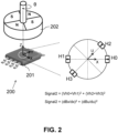
- FIG. 2 shows an angular position sensor system 200 according to another embodiment of the present invention.
- This position sensor system 200 comprises a four-pole magnet 202, e.g. a radially magnetized or axially magnetized four-pole ring magnet or four-pole disk magnet) rotatable around a rotation axis, and a sensor device 201 located in an "on-axis" position (meaning: having a magnetic centre located substantially on the rotation axis).
- the sensor device 201 preferably comprises a semiconductor substrate, and is preferably oriented such that the substrate is substantially orthogonal to the rotation axis.
- the sensor device has four vertical Hall elements H0 to H3 located on a virtual circle, each configured for measuring a radial magnetic field component of the magnet field generated by the magnet 202.
- the vertical Hall elements are oriented such that their axes of maximum sensitivity are directed radially outward (as schematically indicated by the arrow), but the invention will also work if the vertical Hall elements are oriented with their axes of maximum sensitivity radially inwards, or even with some oriented radially inwards, and others radially outwards, if the values are properly added or subtracted.
- the first signal is insensitive to an external disturbance field.
- a second signal is determined which is indicative of a fault or of the integrity of the sensor system, e.g. electrical integrity and/or mechanical integrity. This signal may e.g.
- signal2 Vh0 + Vh1 2 + Vh2 + Vh3 2
- signal2 dBx/dx 2 + dBu/du 2 where the X and U axis define an angle of 45°.
- the sensor device 201 has more than four vertical Hall elements, for example eight vertical Hall elements, located on the imaginary circle, oriented radially inwards or outwards, and spaced apart by 45°.
- the second signal may be calculated as the sum of two terms, each term being the square of a linear combination of four signals, for example a first order polynomial where each of the coefficients is +1 or -1 depending on the orientation of the vertical Hall elements (inwardly or outwardly). As described above, one or more of the coefficients may be different from +1 or -1.
- FIG. 3 shows an angular position sensor system 300 according to another embodiment of the present invention.
- This position sensor system 300 comprises a four-pole magnet 302, e.g. a radially or axially magnetized four-pole ring magnet or four-pole disk magnet) rotatable around a rotation axis, and a sensor device 301 located in an "on-axis" position (meaning: having a magnetic centre located substantially on the rotation axis).
- the sensor device 301 preferably comprises a semiconductor substrate, and is preferably oriented such that the substrate is substantially orthogonal to the rotation axis.
- the sensor device has four vertical Hall elements H0 to H3 located on a virtual circle, and configured for measuring circumferential magnetic field components (i.e.
- the vertical Hall elements H0 to H3 are oriented such that their axes of maximum sensitivity all point in clockwise direction, but the invention will also work if the vertical Hall elements are oriented with their axes of maximum sensitivity pointing in anti-clockwise direction, or even with some oriented in clockwise direction, and others in counter-clockwise direction, if the values are properly added or subtracted.
- the first signal is insensitive to an external disturbance field.
- a second signal is determined which is indicative of a fault or of the integrity of the system, e.g. electrical integrity and/or mechanical integrity. This signal may e.g.
- signal2 Vh0 + Vh1 2 + Vh2 + Vh3 2
- signal 2 dBy / dx 2 + dBv / du 2
- the X,Y,U and V-axis are parallel to the substrate, and where the U-axis, Y-axis and V-axis define an angle of 45°, 90° and 135° respectively with respect to the X-axis in counter-clockwise direction.
- the sensor device has more than four vertical Hall elements, for example eight vertical Hall elements, located on the imaginary circle, oriented such that their axes of maximum sensitivity are tangential to the imaginary circle, and pointing in clockwise or anti-clockwise direction, and spaced apart by 45°.
- the second signal may be calculated as the sum of two terms, each term being the square of a linear combination of four signals, for example a first order polynomial where each of the coefficients is +1 or -1 depending on the orientation of the vertical Hall elements (inwardly or outwardly).
- FIG. 4(a) and FIG. 4(b) shows an angular position sensor system 400 according to another embodiment of the present invention.
- This position sensor system 400 comprises a two-pole magnet, e.g. a bar magnet, or a diametrically or axially magnetized disk magnet or ring magnet, rotatable around a rotation axis, and a sensor device 401 located in an "on-axis" position and having only three, or only four horizontal Hall elements without IMC (Integrated Magnetic Concentrator).
- the sensor device 401 preferably comprises a semiconductor substrate, and is preferably oriented such that the substrate is substantially orthogonal to the rotation axis, hence the horizontal Hall elements are configured for measuring magnetic field components Bz oriented substantially parallel to the rotation axis.
- the sensor device 401 has four horizontal Hall elements H1 to H4, located on a circle, and angularly spaced apart by 90°.
- the first signal is insensitive to an external disturbance field.
- a second signal is determined indicative of a fault or of the integrity of the system, e.g. electrical and/or mechanical integrity of the system. This signal may e.g.
- signal 2 Vh 0 ⁇ Vh 2 2 + Vh 1 ⁇ Vh 3 2
- signal 2 dBz / dx 2 + dBz / dy 2 where the X and Y axis are parallel to the substrate, and define an angle of 90°, and where the Z-axis is perpendicular to the substrate.
- the sensor device 451 has only three horizontal Hall elements, namely one horizontal Hall element Hc located in the centre of a virtual circle, and two horizontal Hall elements H0, H1 located on the circle, and angularly spaced apart by 90°.
- signal 2 Vh 0 ⁇ Vhc 2 + Vh 1 ⁇ Vhc 2
- signal 2 dBz / dx 2 + dBz / dy 2 where the X and Y axis are parallel to the substrate, and define an angle of 90°, and where the Z-axis is perpendicular to the substrate.
- each of the difference signals (Vh1-Vhc) and (Vh0-Vhc) is substantially insensitive to an external disturbance field, and hence also the sum of the squares of these difference signals is highly insensitive to an external disturbance field.
- the sum is constant over the full 360° measurement range.
- an average value or median value may be determined during design and may be hardcoded, or an average value or median value may be determined during a calibration test, and stored in a non-volatile memory 1321 of the sensor device 1320, which may be retrieved during actual use.
- the first threshold may be a value in the range from 75% to 99% of the above mentioned average value, e.g. equal to about 75%, or equal to about 80%, or equal to about 85%, or equal to about 90%, or equal to about 95%, or equal to about 96%, or equal to about 97%, or equal to about 98%.
- the second threshold may be a value in the range from 101% to 125% of the above mentioned average value, e.g. equal to about 102%, or equal to about 103%, or equal to about 104%, or equal to about 105%, or equal to about 110%, or equal to about 115%, or equal to about 120%, or equal to about 125%.
- the difference signals would also have an amplitude of about 1.0, and the average value of the sum of squares would be equal to about 1.0.
- the first threshold would be set at 85% of 1.0 (approximately 0.85)
- the second threshold would be set at 115% of 1.0 (approximately 1.15)
- the second signal will indicate that the "system integrity is OK” if the calculated signal is a value in the range from 0.85 to 1.15, and will indicate that "a fault has occurred” if the calculated sum is a value outside this range.
- each of the difference signals (Vh1-Vhc) and (Vh0-Vhc) is substantially insensitive to an external disturbance field, and hence also the sum of the absolute values of these differences is highly insensitive to an external disturbance field.
- the difference signals will have an amplitude of about 1.0, and the sum of the absolute values of these differences will be values in the range from about 1.00 to about 1.41.
- the average value is equal to about 1.20, and "valid" sums of absolute values of differences are values in the range from about 1.00 to about 1.41, which is about 1.20+/- about 18%.
- a slightly larger tolerance margin may be chosen, for example ⁇ 20%, or ⁇ 22%, or ⁇ 24%, or ⁇ 26%, or ⁇ 28%, or ⁇ 30%.
- this tolerance range the less sensitive the fault detection.
- FIG. 5 shows an angular position sensor system 500 according to another embodiment of the present invention.
- This position sensor system 500 comprises a two-pole magnet (e.g. a diametrically magnetized ring or disk magnet) 502 rotatable around a rotation axis, and a sensor device 501 located in an "off-axis" position, (e.g. "under the ring” or “under the disk") and configured for measuring two circumferential field components (Bx) and two radial magnetic field components (By) as seen by the magnet.
- a two-pole magnet e.g. a diametrically magnetized ring or disk magnet
- a sensor device 501 located in an "off-axis" position, (e.g. "under the ring” or “under the disk") and configured for measuring two circumferential field components (Bx) and two radial magnetic field components (By) as seen by the magnet.
- Bx circumferential field components
- By radial magnetic field components
- the sensor device 501 preferably comprises a semiconductor substrate, and is preferably oriented such that the substrate is substantially orthogonal to the rotation axis.
- the substrate of the sensor device is located at a predefined distance "g" (e.g. from 0.5 to 5.0 mm, e.g. equal to about 2.0 mm) from a bottom or top surface of the ring or disk magnet.
- the magnetic center of the sensor device is located at a distance "Rs" from the rotation axis (e.g. at least 1.4 mm, or at least 1.6 mm, or at least 1.8 mm, or at least 2.0 mm, or at least 2.5 mm, or at least 3.0 mm from the rotation axis).
- the magnet 502 is a ring magnet with an inner radius Ri and an outer radius Ro
- Rs is preferably a value between the inner radius Ri and the outer radius Ro.
- FIG. 5(c) to FIG. 5(d) show various sensor structures which may be used to calculate these gradients.
- the sensor device of FIG. 5(c) uses a so called “dual disk” structure comprising horizontal Hall elements and IMC. More information about this structure can be found in US2018372475 , incorporated herein by reference in its entirety.
- Such disks may for example have a diameter of about 150 to about 250 micron, hence the distance between two corresponding Hall elements may be in the order of about 200 micron.
- the distance between the centres of the two disks may be in the order of 1.5 mm to 2.5 mm, e.g. equal to about 2.0 mm.
- the values of A and B may be dependent on the mounting position (Rs and/or g).
- the value of A and B are preferably chosen such that the second signal is substantially constant for all angular positions.
- the ratio of A/B is substantially equal to K 2 .
- the value of B is chosen equal to 1, and the value of A is chosen equal to K 2 .
- FIG. 6 shows an angular position sensor system 600 according to another embodiment of the present invention, which can be seen as a variant of the position sensor system 500 of FIG. 5 .
- the angular position sensor system 600 of FIG. 6 comprises a two-pole magnet 602 (e.g. a diametrically magnetized two-pole ring magnet or disk magnet) rotatable around a rotation axis, and a sensor device 601 located near a so called “corner position" (e.g. near the periphery of the outer circle of the bottom or top surface of the ring or disk magnet).
- the ring of disk magnet has an outer radius Ro.
- the sensor device 601 preferably comprises a semiconductor substrate, and is preferably oriented such that the substrate is substantially orthogonal to the rotation axis.
- the substrate of the sensor device is located in a plane at a predefined distance "g" (e.g. from 0.5 to 5.0 mm, e.g. equal to about 2.0 mm) from a bottom or top surface of the ring or disk magnet, and the substrate is substantially perpendicular to the rotation axis.
- the magnetic center of the sensor device 601 is located at a distance "Rs" from the rotation axis, which may be a value in the range from about 80% to 120% of Ro, or in the range from about 90% to 110% of Ro.
- the sensor device 601 of FIG. 6 is configured for measuring a circumferential field component (Bx1, Bx2) and an axial field component (Bz1, Bz2) at two different locations X1, X2 along the X-axis.
- an orthogonal coordinate system XYZ is connected to the sensor device, such that the X-axis is tangential to a circumferential direction, the Z-axis is perpendicular to the substrate and parallel to the rotation axis, and the Y-axis is parallel to the substrate and orthogonally intersecting the rotation axis
- FIG. 6(e) and FIG. 6(f) show various sensor structures which may be used to calculate these gradients.
- the sensor device of FIG. 6(e) uses a so called “dual disk” structure comprising horizontal Hall elements and IMC. As mentioned above, more information about this structure can be found in US2018372475 .
- the sensor device of FIG. 6(f) comprises two horizontal Hall elements and two vertical Hall elements, spaced apart by distance "dx" along the X-axis. Using the latter sensor structure, the value of dBx/dx can be calculated as (Vh2-Vh4), and the value of dBz/dx can be calculated as (Vh1-Vh3). But other sensor structures may also be used.
- the second signal indicative of a fault or of the integrity (e.g. (electrical and/or mechanical integrity) of the position sensor system of FIG. 6
- a and B are constants.
- the values of A and B may be dependent on Rs and/or g.
- the value of A and B are preferably chosen such that the second signal is substantially constant for all angular positions.
- the ratio of A/B is substantially equal to K 2 .
- the value of B is chosen equal to 1, and the value of A is chosen equal to K 2 .
- the value(s) of A, B, K may be predefined, e.g. determined during design and e.g. hardcoded, or may be determined during a calibration test, and stored in a non-volatile memory of the sensor device.
- FIG. 7 shows an angular position sensor system 700 according to another embodiment of the present invention, which can be seen as a variant of the sensor system 600 of FIG. 6 .
- the angular position sensor system 700 of FIG. 7 comprises a two-pole magnet 702 (e.g. a diametrically magnetized two-pole ring magnet or disk magnet) rotatable around a rotation axis, and a sensor device 701 located near a so called “corner position" (e.g. near the periphery of the outer circle of the bottom or top surface of the ring or disk magnet).
- the ring of disk magnet has an outer radius Ro.
- the sensor device 801 preferably comprises a semiconductor substrate, and is preferably oriented such that the substrate is substantially parallel to the rotation axis.
- the substrate of the sensor device is substantially located at a predefined distance "g" (e.g. from 0.5 to 5.0 mm, e.g. equal to about 2.0 mm) from a bottom or top surface of the ring or disk magnet.
- the magnetic center of the sensor device 701 is located at a distance "Rs" from the rotation axis, which may be a value in the range from about 80% to 120% of Ro, or in the range from about 90% to 110% of Ro.
- the sensor device 701 of FIG. 7 is configured for measuring a circumferential field component (Bx1, Bx2) and an axial field component (Bz1, Bz2) at two different locations X1, X2 along the X-axis.
- an orthogonal coordinate system XYZ is connected to the sensor device 701, such that the X-axis is tangential to a circumferential direction, the Y-axis is parallel to the substrate and parallel to the rotation axis, and the Z-axis is perpendicular to the substrate and orthogonally intersecting the rotation axis
- FIG. 7(d) and FIG. 7(e) show various sensor structures which may be used to calculate these gradients.
- the sensor device of FIG. 7(d) uses a so called “dual disk” structure comprising horizontal Hall elements and IMC. This may the same dual disk structure as that of FIG. 6(e) , but the signals may be combined differently. As mentioned above, more information about this structure can be found in US2018372475 .
- the sensor device of FIG. 7(e) comprises four vertical Hall elements H1 to H4, two (H2, H4) with their axis of maximum sensitivity oriented in the X-direction, and two (H1, H3) with their axis of maximum sensitivity oriented in the Y-direction, spaced apart by distance "dx" along the X-axis.
- the value of dBx/dx can be calculated as (Vh2-Vh4), and the value of dBy/dx can be calculated as (Vh1-Vh3).
- the values of A and B may be dependent on the mounting position (e.g. on Rs and/or g).
- the value of A and B are preferably chosen such that the second signal is substantially constant for all angular positions.
- the ratio of A/B is substantially equal to K 2 .
- the value of B is chosen equal to 1
- the value of A is chosen equal to K 2 .
- the value(s) of A, B, K may be predefined, e.g. determined during design and e.g. hardcoded, or may be determined during a calibration test, and stored in a non-volatile memory of the sensor device.
- FIG. 7 also works with a four-pole ring or disk magnet, or with a magnet with more than four poles.
- FIG. 8 shows an angular position sensor system 800 according to another embodiment of the present invention.
- the angular position sensor system 800 comprises a four-pole magnet 802 (e.g. an axially magnetized ring magnet, or an axially magnetized disk magnet) rotatable around a rotation axis, and a sensor device 801 located in a so called "off-axis" position (e.g. at a distance of about 0.5 to 5.0 mm above the top surface or below the bottom surface of the magnet), at a distance Rs from the rotation axis.
- the magnet is a ring magnet having an inner radius Ri and an outer radius Ro
- Rs is preferably a value between Ri and Ro, for example substantially halfway between Ri and Ro.
- the sensor device 801 is configured for measuring two circumferential (Bx) and two axial (By) magnetic field components with respect to the magnet.
- the sensor device 801 has a substrate oriented substantially perpendicular to the rotation axis, in the example of FIG. 8 , located at a distance "g" from the bottom surface of the magnet 802.
- the values of A and B may be dependent on the mounting position (e.g. on Rs and/or g).
- the value of A and B are preferably chosen such that the second signal is substantially constant for all angular positions.
- the ratio of A/B is substantially equal to K 2 .
- the value of B is chosen equal to 1, and the value of A is chosen equal to K 2 .
- the value(s) of A, B, K may be predefined, e.g. determined during design and e.g. hardcoded, or may be determined during a calibration test, and stored in a non-volatile memory of the sensor device.
- FIG. 8(c) and FIG. 8(d) show a few examples of sensor structures which may be used to measure said magnetic field components and to determine said gradients, but the present invention is not limited thereto, and other suitable sensor structures may also be used.
- FIG. 8c shows a "dual disk structure" with four horizontal Hall elements and two IMC disks. As mentioned above, the disks may have a diameter of about 200 micron, and may be spaced apart by about 2.0 mm.
- FIG. 8(d) shows a sensor structure with two horizontal Hall elements and two vertical Hall elements, spaced apart by a predefined distance "dx", e.g. in the range from about 1.0 mm to about 3.0 mm, but other suitable distances may also be used.
- the magnet 802 may comprise more than four poles, e.g. six poles or eight poles, or more than eight poles.
- FIG. 9 shows an angular position sensor system 900 according to another embodiment of the present invention.
- the position sensor system 900 comprises a multi-pole magnet 902 (e.g. a radially magnetized ring magnet having at least four, or at least six, or at least eight pole, or more than eight pole pairs) rotatable around a rotation axis, and a sensor device 901.
- a multi-pole magnet 902 e.g. a radially magnetized ring magnet having at least four, or at least six, or at least eight pole, or more than eight pole pairs
- the sensor device 901 is located at a distance "Rs" from the rotation axis, Rs being larger than the outer radius Ro of the magnet.
- the sensor device 901 is configured for measuring a circumferential magnetic field component Bx (tangential to an imaginary circle with radius Rs) and a radial magnetic field component By (with respect to the magnet) at two locations X1, X2 spaced apart along the X-axis, and has a substrate oriented substantially perpendicular to the rotation axis, and located in a plane ⁇ perpendicular to the rotation axis, and substantially midway between the top and bottom plane of the magnet. If the magnet has a thickness T, then the substrate is preferably located at a distance T/2 from the bottom plane and top plane.
- the values of A and B may be dependent on Rs and/or h.
- the value of A and B are preferably chosen such that the second signal is substantially constant for all angular positions.
- the ratio of A/B is substantially equal to K 2 .
- the value of B is chosen equal to 1, and the value of A is chosen equal to K 2 .
- the value(s) of A, B, K may be predefined, e.g. determined during design and e.g. hardcoded, or may be determined during a calibration test, and stored in a non-volatile memory of the sensor device.
- FIG. 9(c) and FIG. 9(d) show a few examples of sensor structures which may be used to measure said magnetic field components and to determine said gradients, but the present invention is not limited thereto, and other suitable sensor structures may also be used.
- FIG. 9(c) shows a so called “dual disk structure" with eight horizontal Hall elements and two IMC disks.
- FIG. 9(d) shows a sensor structure with four vertical Hall elements. But other suitable sensor structures may also be used.
- the magnet 902 may comprise less than eight pole pairs, e.g. four pole pairs or six pole pairs, or more than eight pole pairs, e.g. ten of twelve pole pairs.
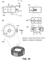
- FIG. 10 shows an angular position sensor system 1000 according to another embodiment of the present invention, which can be seen as a variant of FIG 9 , the main differences being:
- FIG. 10(a) shows a front view
- FIG. 10(b) shows a top view
- FIG. 10(c) shows a side view.
- FIG. 10(d) shows that the sensor device may comprise a "dual disk” structure.
- FIG. 10(e) shows that the sensor device may comprise two vertical Hall elements and two horizontal Hall elements, spaced apart in the X-direction, tangential to an imaginary circle with radius "Rs".
- the radius Rs is larger than the outer radius Ro.
- the values of A and B may be dependent on Rs and/or h.
- the value of A and B are preferably chosen such that the second signal is substantially constant for all angular positions.
- the ratio of A/B is substantially equal to K 2 .
- the value of B is chosen equal to 1, and the value of A is chosen equal to K 2 .
- the value(s) of A, B, K may be predefined, e.g. determined during design and e.g. hardcoded, or may be determined during a calibration test, and stored in a non-volatile memory of the sensor device.
- FIG. 10(d) and FIG. 10(e) show a few examples of sensor structures which may be used to measure said magnetic field components and to determine said gradients, but the present invention is not limited thereto, and other suitable sensor structures may also be used.
- FIG. 10(d) shows a so called “dual disk structure” with eight horizontal Hall elements and two IMC disks.
- FIG. 10(e) shows a sensor structure with two vertical Hall elements and two horizontal Hall elements. But other suitable sensor structures may also be used.
- the reader can find more details about the "dual disk structure" and how this can be used to determine magnetic field gradients, in US2018372475A1 , which is incorporated herein by reference in its entirety.
- FIG. 11 shows a linear position sensor system 1100 according to another embodiment of the present invention.
- the position sensor system 1100 comprises a multi-pole magnetic structure 1102 having an elongated shape extending in a first direction X and having a plurality of magnetic poles magnetised in a second direction Z substantially perpendicular to the first direction X, and a sensor device 1101 configured for measuring two magnetic field components Bx oriented in the first direction X and configured for measuring two magnetic field components Bz oriented in the second direction Z, at two different locations X1, X2 spaced apart in the first direction X, and for calculating a first and second gradient dBx/dx and dBz/dx based on these field components.
- the first signal indicative of an angular position
- signal 1 arctan K ⁇ dBx / dx / dBz / dx
- K is a constant value, which may be chosen such that the magnitude of K times the gradient (dBx/dx) is substantially equal to the magnitude of the gradient (dBz/dx).
- This angular position can be converted into a linear position in known manners (e.g. by multiplying the angular position with a constant, e.g.
- signal 2 A . dBx / dx 2 + B . dBz / dx 2
- FIG. 11(b) and FIG. 11(c) show several sensor structures which can be used to determine said gradients.
- the sensor structure of FIG. 11(b) comprises a so called “dual disk structure" with four Horizontal Hall plates and two IMC disks (in which, simply stated, the Bx component can be determined by subtracting the signals obtained from two corresponding Hall elements located at opposite sides of the same disk, and the Bz component can be determined by adding the signals obtained from these two Hall elements).
- the sensor structure of FIG. 11(c) comprises two horizontal Hall plates H1, H3 configured for measuring Bz at X1 and X2 spaced apart along the X-axis, and two vertical Hall plates H2, H4 configured for measuring Bx at X1 and X2.
- dx is smaller than p/4 or smaller than p/6, or smaller than p/8 or smaller than p/10, or smaller than p/12, p being the distance between centers of adjacent poles. But the invention is not limited hereto, and other values of dx relative to p may also be used.
- FIG. 12 illustrates a flowchart of a method 1200 of determining a first signal (or first value) indicative of a position, and a second signal (or second value) indicative of a fault or of the integrity (e.g. electrical and/or mechanical integrity) of a position sensor system, the system comprising a magnetic source and a sensor device movably mounted relative to the magnetic source, or vice versa, wherein both the first and the second signal are insensitive to an external disturbance field.
- the method 1200 comprises the steps of:
- Step a) may comprise: measuring three magnetic field values oriented in a single direction at three different locations, or measuring two magnetic field values at a first location and measuring two magnetic field values at a second location different from the first location).
- Step b) may comprise: measuring said spatial gradients along a direction of relative movement, for example in case of an angular position sensor system, in a circumferential direction, or in a direction tangential to an imaginary circle having a center located on the rotation axis.
- step b) may comprise: determining differences between signals obtained from various horizontal Hall elements located on a virtual circle, as illustrated for example in FIG. 14(c) or FIG. 14(d) .
- step b) may comprise: determining differences between signals obtained from horizontal Hall elements located on a virtual circle and a signal obtained from a horizontal Hall element located in a center of the circle, as illustrated for example in FIG. 15(c) or FIG. 15(d) .
- step b) may comprise: calculating an average signal of the signals obtained from horizontal Hall elements located on a circle, and calculating differences between signals obtained from the horizontal Hall elements located on the virtual circle and the average signal, as illustrated or example in FIG. 16(c) or FIG. 16(d) .
- the value of N is typically equal to 1 for a two-pole magnet, and is typically equal to 2 for a four-pole magnet.
- step c) may further comprise converting the angular position value into a linear position value, for example by taking into account the number of the pole under which the sensor device is located.
- the method may optionally further comprise step e) of: e) comparing 1205 the second signal with at least one threshold value, and outputting a result of the comparison, for example in the form of a low or high voltage level, corresponding to a "good” or bad system integrity. It is also possible to compare the second signal with more than one threshold value, e.g. with a lower threshold value and with an upper threshold value, and to output a result of the comparison in the form of a "good-signal", a "warning-signal", or an "error-signal".
- a threshold value e.g. with a lower threshold value and with an upper threshold value
- FIG. 13 is a schematic block diagram of an exemplary position sensor device 1302 as can be used in embodiments of the present invention.
- Position sensor devices are known in the art, but a brief description is provided for completeness.
- the position sensor device 1302 of FIG. 13 comprises a plurality of magnetic sensitive elements (e.g. in the example of FIG. 1 eight horizontal Hall elements H0 to H7; in the example of FIG. 2 four vertical Hall elements; etc.), arranged in a particular manner on a semiconductor substrate as described above (e.g. in FIG. 1 to FIG. 11 )
- a plurality of magnetic sensitive elements e.g. in the example of FIG. 1 eight horizontal Hall elements H0 to H7; in the example of FIG. 2 four vertical Hall elements; etc.
- the position sensor device 1302 further comprises a processor or a processing circuit, for example a programmable processing unit 1320 adapted for determining a first and a second gradient signal based on the signals obtained from the magnetic sensor elements, e.g. by summation or subtraction of two or more values.
- a processor or a processing circuit for example a programmable processing unit 1320 adapted for determining a first and a second gradient signal based on the signals obtained from the magnetic sensor elements, e.g. by summation or subtraction of two or more values.
- the processing unit 1320 is preferably further adapted for determining a position, e.g. an angular position based on a ratio of these gradient signals, for example using a look-up table and interpolation, or by making use of goniometric functions (e.g. an arctangent function) or in any other suitable way.
- a position e.g. an angular position based on a ratio of these gradient signals
- goniometric functions e.g. an arctangent function
- the processing unit 1320 may be further adapted for converting this angular position value into a linear position value.
- the position value may be output by the controller as a first output signal "POS".
- the controller also calculates and optionally also outputs a second signal "signal2", indicative of a fault or of the integrity of the system, or a value derived therefrom, for example after comparing the second signal with one or more predefined threshold values.
- the controller 1320 is configured for testing whether the second signal lies in a first predefined range, and if the outcome of this test is TRUE, the controller outputs an integrity signal "INT" having a first level (e.g. logical '1') corresponding to a "good” situation, and if the outcome of the test is FALSE, the controller outputs an integrity signal having a second level (e.g. a logical '0') corresponding to a "bad” situation, or vice versa.
- the output signals may be provided as digital signals, or as analog signals, or combinations hereof.
- the sensor device 1320 typically further comprises biasing circuitry, readout circuitry, one or more amplifiers, analog-to-digital convertors (ADC), etc. Such circuits are well known in the art, but are not the main focus of the present invention.
- the present invention is mainly described with horizontal Hall elements and/or vertical Hall elements, the present invention is not limited to this type of magnetic sensitive elements, and other types of magnetic sensor elements may also be used, for example circular Hall elements, or magneto-resistive elements, e.g. XMR or GMR elements.
- FIG. 14 (a) and FIG. 14(b) show another embodiment of a sensor system 1400 comprising a two-pole magnet 1402 and a sensor device 1401 comprising three horizontal Hall elements H1, H2, H3 located on a virtual circle and angularly spaced apart by multiples of 120°.
- the magnet 1402 may be an axially or a diametrically magnetized ring or disk magnet.
- the center of the virtual circle is preferably located on the rotation axis of the magnet.
- Each of the horizontal Hall elements H1, H2, H3 measures a magnetic field component Bz oriented in the Z-direction, perpendicular to the semiconductor substrate.
- the values provided by the Hall elements H1, H2, H3 are Vh1, Vh2, and Vh3 respectively.
- FIG. 14(a) is a schematic representation of the sensor device 1401.
- FIG. 14(b) is a perspective view of the sensor system 1400.
- FIG. 14(c) shows simulation results of a sum of squares of differences between pairs of two magnetic field components, e.g. in accordance with the formula:
- Signal 2 Vh 1 ⁇ Vh 2 2 + Vh 2 ⁇ Vh 3 2 + Vh 3 ⁇ Vh 1 2
- signal2 is the signal indicative of a fault
- Vh1, Vh2 and Vh3 are signals provided by the horizontal Hall elements (or derived therefrom, e.g. after amplification, digitization, etc.).
- each of the difference signals (Vh1-Vh2), (Vh2-Vh3), and (Vh3-Vh1) is substantially insensitive to an external disturbance field, and hence also the sum of the squares of these difference signals is highly insensitive to an external disturbance field.
- the sum of squares is constant over the full 360° measurement range. In practice, there may be a small variation on the signal (e.g. due to differences in magnetic sensitivity of the sensor elements).
- calculating the sum and by comparing the sum with a first threshold smaller than said constant, and/or by comparing the sum with a second threshold larger than said constant and by testing whether the sum is a value smaller than the lower threshold, and/or larger than the upper threshold, and/or a value between these two thresholds, it is possible to detect certain faults.
- an average value or median value may be determined during design and may be hardcoded, or an average value or median value may be determined during a calibration test, and stored in a non-volatile memory of the sensor device, which may be retrieved during actual use.
- the first threshold may be a value in the range from 75% to 99% of the above mentioned average value, e.g. equal to about 75%, or equal to about 80%, or equal to about 85%, or equal to about 90%, or equal to about 95%, or equal to about 96%, or equal to about 97%, or equal to about 98%.
- the second threshold may be a value in the range from 101% to 125% of the above mentioned average value, e.g. equal to about 102%, or equal to about 103%, or equal to about 104%, or equal to about 105%, or equal to about 110%, or equal to about 115%, or equal to about 120%, or equal to about 125%.
- the second signal will indicate that the "system integrity is OK" if the calculated signal is a value in the range from 3.83 to 5.18, and will indicate that "a fault has occurred” if the calculated sum is a value outside this range.
- each of the difference signals (Vh1-Vh2), (Vh2-Vh3), and (Vh3-Vh1) is substantially insensitive to an external disturbance field, and hence also the sum of the absolute values of these differences is highly insensitive to an external disturbance field.
- the difference signals will have an amplitude of about 1.73, and the sum of the absolute values of these differences will be values in the range from about 3.00 to about 3.46.
- the average value is equal to about 3.23, and "valid" sums of absolute values of differences are values in the range from about 3.00 to about 3.46, which is about 3.23+/- about 7%.
- a slightly larger tolerance margin may be chosen, for example ⁇ 10%, or ⁇ 12%, or ⁇ 14%, or ⁇ 16%, or ⁇ 18%, or ⁇ 20%.
- this tolerance range the less sensitive the fault detection.
- FIG. 15 (a) and FIG. 15(b) show another embodiment of a sensor system 1500 comprising a two-pole magnet and a sensor device 1501 comprising three horizontal Hall elements H1, H2, H3 located on a circle and angularly spaced apart by multiples of 120°, and a fourth horizontal Hall element Hc located in the center of the circle.
- the magnet may be an axially or a diametrically magnetized ring or disk magnet.
- the center of the virtual circle is preferably located on the rotation axis of the magnet.
- Each of the horizontal Hall elements H1, H2, H3, Hc measures a magnetic field component Bz oriented in the Z-direction, perpendicular to the semiconductor substrate.
- the values provided by the Hall elements H1, H2, H3, Hc are Vh1, Vh2, Vh3, Vhc respectively.
- FIG. 15(a) is a schematic representation of the sensor device 1501.
- FIG. 15(b) is a perspective view of the sensor system 1500.
- each of the difference signals (Vh1-Vhc), (Vh2-Vhc), and (Vh3-Vhc) is substantially insensitive to an external disturbance field, and hence also the sum of the squares of these difference signals is highly insensitive to an external disturbance field.
- the sum is constant over the full 360° measurement range.
- there may be a small variation on the signal e.g. due to differences of magnetic sensitivity of the sensor elements.
- an average value or median value may be determined during design and may be hardcoded, or an average value or median value may be determined during a calibration test, and stored in a non-volatile memory of the sensor device, which may be retrieved during actual use.
- the first threshold may be a value in the range from 75% to 99% of the above mentioned average value, e.g. equal to about 75%, or equal to about 80%, or equal to about 85%, or equal to about 90%, or equal to about 95%, or equal to about 96%, or equal to about 97%, or equal to about 98%.
- the second threshold may be a value in the range from 101% to 125% of the above mentioned average value, e.g. equal to about 102%, or equal to about 103%, or equal to about 104%, or equal to about 105%, or equal to about 110%, or equal to about 115%, or equal to about 120%, or equal to about 125%.
- the difference signals would also have an amplitude of about 1.0, and the average value would be equal to about 1.5.
- the first threshold would be set at 85% of 1.5 (approximately 1.28)
- the second threshold would be set at 115% of 1.5 (approximately 1.73)
- the second signal will indicate that the no fault is detected (thus the system integrity is good) if the calculated signal is a value in the range from 1.28 to 1.73, and will indicate that "a fault is detected" if the calculated sum is a value outside this range.
- Vhc is the signal provided by the central Hall element Hc (or derived therefrom). Since the horizontal Hall elements are oriented in the same (Z) direction, each of the difference signals (Vh1-Vhc), (Vh2-Vhc), and (Vh3-Vhc) is substantially insensitive to an external disturbance field, and hence also the sum of the absolute values of these differences is highly insensitive to an external disturbance field.
- the difference signals will also have an amplitude of about 1.0, and the sum of the absolute values of these differences will be values in the range from about 1.73 to about 2.00.
- the average value is equal to about 1.87, and "valid" sums of absolute values of differences are values in the range from about 1.73 to about 2.00, which is about 1.87+/- about 7%.
- a slightly larger tolerance margin may be chosen, for example ⁇ 10%, or ⁇ 12%, or ⁇ 14%, or ⁇ 16%, or ⁇ 18%, or ⁇ 20%.
- this tolerance range the less sensitive the fault detection.
- FIG. 16 (a) and FIG. 16(b) show another embodiment of a sensor system 1600 comprising a two-pole magnet and a sensor device 1601 comprising three horizontal Hall elements H1, H2, H3 located on a circle and angularly spaced apart by multiples of 120°.
- FIG. 16(c) shows simulation results of a sum of squares of differences between each magnetic field component and said average signal. This simulation provides the same result as shown in FIG. 15(c) , and all that is mentioned above is also applicable here.
- FIG. 16(d) shows simulation results of a sum of absolute values of differences between each magnetic field component and said average signal. This simulation provides the same result as shown in FIG. 15(d) , and all that is mentioned above is also applicable here.
- FIG. 14(a)-(d) , FIG. 15(a)-(d) and FIG. 16(a)-(d) are shown for a sensor system comprising a two-pole magnet and a sensor device comprising three horizontal Hall elements arranged on a circle, and optionally one central Hall element, the same principles also apply to a sensor system (not shown) comprising a four-pole magnet (e.g. a four-pole ring or disk magnet) and a sensor device (not shown) comprising six horizontal Hall elements arranged on a circle, angularly spaced apart by multiples of 60°, and optionally a central element Hc.
- a second signal in the form of a sum of absolute values is explicitly described above only for the systems shown in FIG. 4(c) , FIG. 14(b) , FIG. 15(b) and FIG. 16(b) , it shall be clear to the skilled reader having the benefit of the present disclosure, that also in the other systems described above, a second signal in the form of a sum of squares of gradients or differences can be used, or in the form of a sum of absolute values of gradients or differences can be used, or in the form of another function which is substantially constant over the measurement range, such as for example a polynomial function of a degree of at least two, for example a polynomial comprising only second order and fourth order terms, or a polynomial comprising only even order terms, but the present invention is not limited hereto, as long as the invention is defined by the appended claims.
Landscapes
- Physics & Mathematics (AREA)
- General Physics & Mathematics (AREA)
- Condensed Matter Physics & Semiconductors (AREA)
- Transmission And Conversion Of Sensor Element Output (AREA)
- Measurement Of Length, Angles, Or The Like Using Electric Or Magnetic Means (AREA)
Claims (14)
- Système de capteur de position (100 ; 200 ; 300 ; 400 ; 500 ; 600 ; 700 ; 800 ; 900 ; 1000 ; 1100 ; 1400; 1500; 1600), comprenant :une source de champ magnétique (102 ; 202 ; 302 ; 402 ; 502 ; 602 ; 702 ; 802 ; 902 ; 1002 ; 1102 ; 1402 ; 1502 ; 1602) destinée à générer un champ magnétique ;un dispositif de capteur de position (101; 201; 301; 401; 501; 601; 701; 801; 901; 1001 ; 1101; 1401; 1501 ; 1601) mobile par rapport à la source de champ magnétique ou inversement,le dispositif de capteur de position comprenant :caractérisé en ce que- au moins trois éléments sensibles magnétiques (1311; 1312 ; 1313) destinés à mesurer au moins trois valeurs de champ magnétique dudit champ magnétique ; et- un circuit de traitement (1320) configuré pour obtenir lesdites au moins trois valeurs de champ magnétique, et pour déterminer au moins deux gradients de champ magnétique ou au moins deux différences de champ magnétique sur la base desdites au moins trois valeurs de champ magnétique, et pour dériver à partir desdits au moins deux gradients de champ magnétique ou à partir desdites au moins deux différences de champ magnétique un premier signal (POS) indicatif d'une position de la source magnétique par rapport au dispositif de capteur de position ;- le circuit de traitement (1320) est en outre configuré pour fournir un deuxième signal (signal2 ; signal2' ; INT) indicatif d'une défaillance ou d'une intégrité du système de capteur de position ;- le deuxième signal est dérivé desdits au moins deux gradients de champ magnétique ou desdites au moins deux différences de champ magnétique ;- le dispositif de capteur de position est en outre configuré pour fournir en sortie ce deuxième signal (signal2; signal2' ; INT).
- Système de capteur de position (100 ; 200 ; 300 ; 400 ; 500 ; 600 ; 700 ; 800 ; 900 ; 1000 ; 1100 ; 1400; 1500; 1600) selon la revendication 1,dans lequel le dispositif de capteur (101; 201; 301; 401; 501; 601; 701; 801; 901; 1001 ; 1101; 1401; 1501; 1601) est en outre configuré pour déterminer ledit deuxième signal (signal2 ; signal2' ; INT) en tant qu'expression polynomiale desdits au moins deux gradients de champ magnétique, l'expression polynomiale ayant un ordre d'au moins deux ;ou dans lequel le dispositif de capteur (101 ; 201; 301 ; 401 ; 501 ; 601 ; 701; 801; 901 ; 1001 ; 1101; 1401; 1501; 1601) est en outre configuré pour déterminer ledit deuxième signal (signal2 ; signal2' ; INT) en tant qu'expression polynomiale desdites au moins deux différences, l'expression polynomiale ayant un ordre d'au moins deux ;ou dans lequel le dispositif de capteur (101 ; 201; 301 ; 401 ; 501 ; 601 ; 701 ; 801 ; 901 ; 1001 ; 1101; 1401; 1501; 1601) est en outre configuré pour déterminer ledit deuxième signal (signal2 ; signal2' ; INT) en tant que somme de carrés desdits au moins deux gradients de champ magnétique ;ou dans lequel le dispositif de capteur (101 ; 201; 301 ; 401 ; 501 ; 601 ; 701 ; 801 ; 901 ; 1001 ; 1101; 1401; 1501; 1601) est en outre configuré pour déterminer ledit deuxième signal (signal2 ; signal2' ; INT) en tant que somme de carrés desdites au moins deux différences ;ou dans lequel le dispositif de capteur (101 ; 201; 301 ; 401 ; 501 ; 601 ; 701 ; 801 ; 901 ; 1001 ; 1101; 1401; 1501; 1601) est en outre configuré pour déterminer ledit deuxième signal (signal2 ; signal2' ; INT) en tant que somme de valeurs absolues desdits au moins deux gradients de champ magnétique ;ou dans lequel le dispositif de capteur (101 ; 201; 301 ; 401 ; 501 ; 601 ; 701 ; 801 ; 901 ; 1001 ; 1101; 1401; 1501; 1601) est en outre configuré pour déterminer ledit deuxième signal (signal2 ; signal2' ; INT) en tant que somme de valeurs absolues desdites au moins deux différences.
- Système de capteur de position (100 ; 200 ; 300 ; 400 ; 500 ; 600 ; 700 ; 800 ; 900 ; 1000 ; 1100 ; 1400; 1500; 1600) selon l'une quelconque des revendications précédentes,
dans lequel le dispositif de capteur (101 ; 201 ; 301 ; 401 ; 501 ; 601 ; 701 ; 801 ; 901 ; 1001 ; 1101; 1401; 1501 ; 1601) est en outre configuré pour comparer le deuxième signal (signal2 ; signal2' ; INT) avec au moins une valeur seuil (T1), et pour fournir un signal de sortie correspondant à un résultat de l'au moins une comparaison. - Système de capteur de position (100; 200; 300; 400; 1400; 1500; 1600) selon l'une quelconque des revendications précédentes,dans lequel la source de champ magnétique (102 ; 202 ; 302 ; 402 ; 1402 ; 1502 ; 1602) est un aimant permanent, pouvant tourner autour d'un axe de rotation ;et dans lequel le dispositif de capteur (101 ; 201 ; 301 ; 401 ; 1401 ; 1501 ; 1601) est configuré pour déterminer une position angulaire, et est situé sensiblement sur ledit axe.
- Système de capteur de position (100; 200 ; 300) selon la revendication 4,dans lequel la source de champ magnétique (102 ; 202 ; 302) est un aimant permanent ayant au moins quatre pôles,et dans lequel le dispositif de capteur (101; 201 ; 301) comprend un substrat semi-conducteur orienté sensiblement orthogonalement à l'axe de rotation, le substrat semi-conducteur comprenant une pluralité d'au moins quatre paires d'éléments de capteur, chaque paire étant configurée pour mesurer des valeurs de champ magnétique (Bx, By, Bu, Bv) dans différentes directions (X, Y, U, V) parallèles au substrat ;et dans lequel le dispositif de capteur (101; 201 ; 301) est en outre configuré pour déterminer au moins quatre gradients de champ magnétique ou différences de champ magnétique associés auxdites au moins quatre paires de signaux.
- Système de capteur de position (100 ; 200 ; 300) selon la revendication 5,dans lequel la source de champ magnétique (102 ; 202 ; 302) est un aimant permanent ayant quatre pôles;et dans lequel le substrat semi-conducteur comprend au moins huit éléments de capteur (H0 à H8) situés sur un cercle virtuel ;et dans lequel le dispositif de capteur (101; 201 ; 301) est configuré pour déterminer au moins quatre gradients de champ magnétique (dBx/dy, dBy/dx, dBu/dv, dBv/du) le long d'au moins quatre directions différentes parallèles au substrat et espacées angulairement de 45° ;et dans lequel le deuxième signal (signal2 ; signal2' ; INT) est calculé conformément à la formule suivante :
 ou une valeur dérivée de celle-ci.
 - Système de capteur de position (400) selon l'une quelconque des revendications 1 à 4,dans lequel la source de champ magnétique (402) est un aimant permanent bipolaire ;et dans lequel le dispositif de capteur (401) comprend : un substrat semi-conducteur orienté sensiblement orthogonalement à l'axe de rotation, le substrat semi-conducteur comprenant au moins trois ou au moins quatre éléments de capteur, chaque élément de capteur étant configuré pour mesurer une composante de champ magnétique (Bz) orientée dans une direction sensiblement perpendiculaire au substrat semi-conducteur;et dans lequel le dispositif de capteur (401) est en outre configuré pour déterminer deux gradients de champ magnétique (dBz/dx ; dBz/dy) desdites valeurs de champ magnétique (Bz) le long de deux directions orthogonales (X, Y) parallèles au substrat semi-conducteur.
- Système de capteur de position (500 ; 600 ; 700 ; 800 ; 900 ; 1000) selon l'une quelconque des revendications 1 à 3,dans lequel la source de champ magnétique (502 ; 602 ; 702 ; 802 ; 902 ; 1002) est un aimant permanent, pouvant tourner autour d'un axe de rotation ;et dans lequel le dispositif de capteur (501 ; 601; 701; 801 ; 901 ; 1001) est configuré pour déterminer une position angulaire, et est situé à une distance non nulle dudit axe de rotation.
- Système de capteur de position (500) selon la revendication 8,dans lequel la source de champ magnétique (502) est un aimant permanent bipolaire ;et dans lequel le dispositif de capteur (501) est configuré pour mesurer des premières composantes de champ magnétique (Bx) orientées dans une direction circonférentielle (X) autour de l'axe de rotation, et des deuxièmes composantes de champ magnétique (By) orientées dans une direction radiale (Y) vis-à-vis de l'axe de rotation ;et dans lequel le dispositif de capteur (501) est configuré pour déterminer un premier gradient de champ magnétique (dBx/dx) des premières composantes de champ magnétique (Bx) le long de ladite direction circonférentielle (X), et pour déterminer un deuxième gradient de champ magnétique (dBy/dx) des deuxièmes composantes de champ magnétique (By) le long de ladite direction circonférentielle (X) ;et dans lequel le dispositif de capteur (501) est en outre configuré pour calculer le deuxième signal (signal2 ; signal2' ; INT) en fonction de ces premier et deuxième gradients de champ magnétique.
- Système de capteur de position (600 ; 700) selon la revendication 8,dans lequel la source de champ magnétique (602 ; 702) est un aimant permanent bipolaire ;et dans lequel le dispositif de capteur (701; 801) est configuré pour mesurer des premières composantes de champ magnétique (Bx) orientées dans une direction circonférentielle (X) autour de l'axe de rotation, et des deuxièmes composantes de champ magnétique (Bz) orientées dans une direction (Z) parallèle à l'axe de rotation ;et dans lequel le dispositif de capteur (701; 801) est configuré pour déterminer un premier gradient de champ magnétique (dBx/dx) des premières composantes de champ magnétique (Bx) le long de ladite direction circonférentielle (X), et pour déterminer un deuxième gradient de champ magnétique (dBz/dx) des deuxièmes composantes de champ magnétique (Bz) le long de ladite direction circonférentielle (X) ;et dans lequel le dispositif de capteur est en outre configuré pour calculer le deuxième signal (signal2 ; signal2' ; INT) en fonction de ces premier et deuxième gradients de champ magnétique.
- Système de capteur de position (800) selon la revendication 8,dans lequel la source de champ magnétique (802) est un aimant permanent ayant au moins quatre pôles;et dans lequel le dispositif de capteur (801) est configuré pour mesurer des premières composantes de champ magnétique (Bx) orientées dans une direction circonférentielle (X) autour de l'axe de rotation, et des deuxièmes composantes de champ magnétique (Bz) orientées dans une direction (Z) parallèle à l'axe de rotation ;et dans lequel le dispositif de capteur (801) est configuré pour déterminer un premier gradient de champ magnétique (dBx/dx) des premières composantes de champ magnétique (Bx) le long de ladite direction circonférentielle (X), et pour déterminer un deuxième gradient de champ magnétique (dBz/dx) des deuxièmes composantes de champ magnétique (Bz) le long de ladite direction circonférentielle (X) ;et dans lequel le dispositif de capteur est en outre configuré pour calculer le deuxième signal (signal2 ; signal2' ; INT) en fonction de ces premier et deuxième gradients de champ magnétique.
- Système de capteur de position (900 ; 1000) selon la revendication 8,dans lequel la source de champ magnétique (902 ; 1002) est un aimant permanent ayant au moins quatre pôles ;et dans lequel le dispositif de capteur (901; 1001) est configuré pour mesurer des premières composantes de champ magnétique (Bx) orientées dans une direction circonférentielle (X) autour de l'axe de rotation, et des deuxièmes composantes de champ magnétique (Br) orientées dans une direction radiale vis-à-vis de l'aimant permanent ;et dans lequel le dispositif de capteur (901; 1001) est configuré pour déterminer un premier gradient de champ magnétique (dBx/dx) des premières composantes de champ magnétique (Bx) le long de ladite direction circonférentielle (X), et pour déterminer un deuxième gradient de champ magnétique (dBr/dx) des deuxièmes composantes de champ magnétique (Br) le long de ladite direction circonférentielle (X) ;et dans lequel le dispositif de capteur (901; 1001) est en outre configuré pour calculer le deuxième signal (signal2 ; signal2' ; INT) en fonction de ces premier et deuxième gradients de champ magnétique.
- Système de capteur de position (1100) selon l'une quelconque des revendications 1 à 3,dans lequel la source de champ magnétique (1102) est une structure magnétique ayant une forme allongée s'étendant dans une première direction (X) et ayant une pluralité d'au moins deux ou d'au moins trois ou d'au moins quatre pôles magnétiques magnétisés dans une deuxième direction (Z) sensiblement perpendiculaire à la première direction (X) ;dans lequel le dispositif de capteur (1101) est mobile dans la première direction (X) par rapport à la structure magnétique, ou inversement, et est configuré pour déterminer une position linéaire dans la première direction (X) ;dans lequel une distance entre le dispositif de capteur (1101) et la structure magnétique (1102) est sensiblement constante ;dans lequel le dispositif de capteur (1101) est configuré pour mesurer des premières composantes de champ magnétique (Bx) orientées dans la première direction (X), et des deuxièmes composantes de champ magnétique (Bz) orientées dans la deuxième direction (Z) ;dans lequel le dispositif de capteur (1101) est configuré pour déterminer un premier gradient de champ magnétique (dBx/dx) de la première composante de champ magnétique (Bx) le long de ladite première direction (X), et pour déterminer un deuxième gradient de champ magnétique (dBz/dx) de la deuxième composante de champ magnétique (Bz) le long de ladite première direction (X) ;et dans lequel le dispositif de capteur (1101) est configuré pour calculer le deuxième signal (signal2 ; signal2' ; INT) en fonction de ces premier et deuxième gradients de champ magnétique.
- Procédé (1200) de détermination d'une position et de détermination d'une défaillance ou d'une intégrité d'un système de capteur (100 ; 200 ; 300 ; 400 ; 500 ; 600 ; 700 ; 800 ; 900 ; 1000 ; 1100 ; 1400 ; 1500 ; 1600) selon l'une quelconque des revendications précédentes, le procédé comprenant les étapes suivantes:a) mesurer (1201) au moins trois valeurs de champ magnétique dudit champ magnétique ;b) déterminer (1202) au moins deux gradients de champ magnétique, ou au moins deux ou au moins trois différences de champ magnétique sur la base desdites au moins trois valeurs de champ magnétique ;c) dériver (1203) à partir desdits au moins deux gradients de champ magnétique ou à partir desdites au moins deux ou desdites au moins trois différences de champ magnétique un premier signal (POS) indicatif d'une position du dispositif de capteur ;caractérisé en ce que le procédé comprend en outre les étapes suivantes :d) dériver (1204) à partir desdits au moins deux gradients de champ magnétique ou à partir desdites au moins deux ou desdites au moins trois différences de champ magnétique un deuxième signal (signal2 ; signal2' ; INT) indicatif d'une défaillance ou d'une intégrité du système de capteur de position ;e) fournir en sortie ce deuxième signal (signal2 ; signal2' ; INT).
Priority Applications (1)
| Application Number | Priority Date | Filing Date | Title |
|---|---|---|---|
| EP23207113.4A EP4296623A3 (fr) | 2019-12-30 | 2020-12-07 | Système et procédé de capteur de position magnétique |
Applications Claiming Priority (1)
| Application Number | Priority Date | Filing Date | Title |
|---|---|---|---|
| EP19220092 | 2019-12-30 |
Related Child Applications (1)
| Application Number | Title | Priority Date | Filing Date |
|---|---|---|---|
| EP23207113.4A Division EP4296623A3 (fr) | 2019-12-30 | 2020-12-07 | Système et procédé de capteur de position magnétique |
Publications (2)
| Publication Number | Publication Date |
|---|---|
| EP3845864A1 EP3845864A1 (fr) | 2021-07-07 |
| EP3845864B1 true EP3845864B1 (fr) | 2023-11-22 |
Family
ID=69055876
Family Applications (2)
| Application Number | Title | Priority Date | Filing Date |
|---|---|---|---|
| EP20212323.8A Active EP3845864B1 (fr) | 2019-12-30 | 2020-12-07 | Système et procédé de capteur de position magnétique |
| EP23207113.4A Pending EP4296623A3 (fr) | 2019-12-30 | 2020-12-07 | Système et procédé de capteur de position magnétique |
Family Applications After (1)
| Application Number | Title | Priority Date | Filing Date |
|---|---|---|---|
| EP23207113.4A Pending EP4296623A3 (fr) | 2019-12-30 | 2020-12-07 | Système et procédé de capteur de position magnétique |
Country Status (3)
| Country | Link |
|---|---|
| US (2) | US11668770B2 (fr) |
| EP (2) | EP3845864B1 (fr) |
| CN (1) | CN113124741A (fr) |
Families Citing this family (4)
| Publication number | Priority date | Publication date | Assignee | Title |
|---|---|---|---|---|
| US11933933B2 (en) * | 2021-03-31 | 2024-03-19 | Asahi Kasei Microdevices Corporation | Event detection method, event detection system, and non-transitory computer-readable recording medium |
| DE102021118347A1 (de) * | 2021-07-15 | 2023-01-19 | Infineon Technologies Ag | Systeme; vorrichtungen und verfahren zur magnetischen positionserkennung |
| CN116358562B (zh) * | 2023-05-31 | 2023-08-01 | 氧乐互动(天津)科技有限公司 | 消毒操作轨迹检测方法、装置、设备和存储介质 |
| CN117054936B (zh) * | 2023-10-12 | 2024-01-12 | 江苏多维科技有限公司 | 一种梯度传感器 |
Family Cites Families (6)
| Publication number | Priority date | Publication date | Assignee | Title |
|---|---|---|---|---|
| GB2505226A (en) | 2012-08-23 | 2014-02-26 | Melexis Technologies Nv | Arrangement, method and sensor for measuring an absolute angular position using a multi-pole magnet |
| US9915552B2 (en) | 2013-11-19 | 2018-03-13 | Infineon Technologies Ag | Perpendicular gradiometric angle sensors, systems and methods |
| KR20170103979A (ko) * | 2015-01-23 | 2017-09-13 | 인피니언 테크놀로지스 아게 | 축외 자기 각도 감지 시스템 |
| JP6550099B2 (ja) | 2017-06-26 | 2019-07-24 | メレキシス テクノロジーズ エス エー | 回転角検出装置、姿勢制御装置、自動操舵装置及びスロットル装置 |
| EP3543656A1 (fr) * | 2018-03-24 | 2019-09-25 | Melexis Technologies SA | Aimant multipolaire insensible hors-axe et système de détection le comprenant |
| US20200284615A1 (en) * | 2019-03-05 | 2020-09-10 | Infineon Technologies Ag | Multilayered safety mechanism for a three-phase off-axis angle sensor |
-
2020
- 2020-12-07 EP EP20212323.8A patent/EP3845864B1/fr active Active
- 2020-12-07 EP EP23207113.4A patent/EP4296623A3/fr active Pending
- 2020-12-15 US US17/122,163 patent/US11668770B2/en active Active
- 2020-12-25 CN CN202011560744.0A patent/CN113124741A/zh active Pending
-
2023
- 2023-04-21 US US18/304,570 patent/US20230251332A1/en active Pending
Also Published As
| Publication number | Publication date |
|---|---|
| EP3845864A1 (fr) | 2021-07-07 |
| CN113124741A (zh) | 2021-07-16 |
| US11668770B2 (en) | 2023-06-06 |
| EP4296623A2 (fr) | 2023-12-27 |
| EP4296623A3 (fr) | 2024-03-13 |
| US20210199730A1 (en) | 2021-07-01 |
| US20230251332A1 (en) | 2023-08-10 |
Similar Documents
| Publication | Publication Date | Title |
|---|---|---|
| EP3845864B1 (fr) | Système et procédé de capteur de position magnétique | |
| JP6549676B2 (ja) | 絶対角度位置の測定 | |
| JP6236452B2 (ja) | 多極磁石を用いて絶対角度位置を測定する装置、方法、及びセンサ | |
| CN110645882B (zh) | 稳健对抗干扰场的位置传感器系统和方法 | |
| JP5613839B2 (ja) | 移動する物体の絶対的な位置特定のための方法及び装置 | |
| US20220357144A1 (en) | Angular position sensor system | |
| US11852555B2 (en) | Stray-field-immune magnetic field sensor arrangement, magnetic torque sensor arrangement and method for determining a magnetic flux | |
| EP3875915B1 (fr) | Dispositif, système et procédé de détermination de la position d'un aimant | |
| US11774234B2 (en) | Angle sensor calibration method for safety measure without full rotation | |
| EP4105768B1 (fr) | Dispositif et procédé pour déterminer l'orientation d'un aimant et manette de jeu | |
| US11982547B2 (en) | Magnetic position sensor system, method and device with error detection | |
| US20220349730A1 (en) | Reliable position sensor | |
| EP4206613B1 (fr) | Dispositif, procédé et système de capteur de position magnétique avec détection d'erreur | |
| US11788866B2 (en) | Magnetic position sensor device, method and system, with error detection | |
| US11789092B2 (en) | Magnetic sensor devices, systems and methods with error detection |
Legal Events
| Date | Code | Title | Description |
|---|---|---|---|
| PUAI | Public reference made under article 153(3) epc to a published international application that has entered the european phase |
Free format text: ORIGINAL CODE: 0009012 |
|
| STAA | Information on the status of an ep patent application or granted ep patent |
Free format text: STATUS: THE APPLICATION HAS BEEN PUBLISHED |
|
| AK | Designated contracting states |
Kind code of ref document: A1 Designated state(s): AL AT BE BG CH CY CZ DE DK EE ES FI FR GB GR HR HU IE IS IT LI LT LU LV MC MK MT NL NO PL PT RO RS SE SI SK SM TR |
|
| STAA | Information on the status of an ep patent application or granted ep patent |
Free format text: STATUS: REQUEST FOR EXAMINATION WAS MADE |
|
| 17P | Request for examination filed |
Effective date: 20211115 |
|
| RBV | Designated contracting states (corrected) |
Designated state(s): AL AT BE BG CH CY CZ DE DK EE ES FI FR GB GR HR HU IE IS IT LI LT LU LV MC MK MT NL NO PL PT RO RS SE SI SK SM TR |
|
| STAA | Information on the status of an ep patent application or granted ep patent |
Free format text: STATUS: EXAMINATION IS IN PROGRESS |
|
| 17Q | First examination report despatched |
Effective date: 20221013 |
|
| GRAP | Despatch of communication of intention to grant a patent |
Free format text: ORIGINAL CODE: EPIDOSNIGR1 |
|
| STAA | Information on the status of an ep patent application or granted ep patent |
Free format text: STATUS: GRANT OF PATENT IS INTENDED |
|
| GRAJ | Information related to disapproval of communication of intention to grant by the applicant or resumption of examination proceedings by the epo deleted |
Free format text: ORIGINAL CODE: EPIDOSDIGR1 |
|
| STAA | Information on the status of an ep patent application or granted ep patent |
Free format text: STATUS: EXAMINATION IS IN PROGRESS |
|
| INTG | Intention to grant announced |
Effective date: 20230905 |
|
| GRAP | Despatch of communication of intention to grant a patent |
Free format text: ORIGINAL CODE: EPIDOSNIGR1 |
|
| STAA | Information on the status of an ep patent application or granted ep patent |
Free format text: STATUS: GRANT OF PATENT IS INTENDED |
|
| GRAS | Grant fee paid |
Free format text: ORIGINAL CODE: EPIDOSNIGR3 |
|
| GRAA | (expected) grant |
Free format text: ORIGINAL CODE: 0009210 |
|
| STAA | Information on the status of an ep patent application or granted ep patent |
Free format text: STATUS: THE PATENT HAS BEEN GRANTED |
|
| INTC | Intention to grant announced (deleted) | ||
| INTG | Intention to grant announced |
Effective date: 20231016 |
|
| AK | Designated contracting states |
Kind code of ref document: B1 Designated state(s): AL AT BE BG CH CY CZ DE DK EE ES FI FR GB GR HR HU IE IS IT LI LT LU LV MC MK MT NL NO PL PT RO RS SE SI SK SM TR |
|
| REG | Reference to a national code |
Ref country code: GB Ref legal event code: FG4D |
|
| REG | Reference to a national code |
Ref country code: CH Ref legal event code: EP |
|
| REG | Reference to a national code |
Ref country code: DE Ref legal event code: R096 Ref document number: 602020021419 Country of ref document: DE |
|
| REG | Reference to a national code |
Ref country code: IE Ref legal event code: FG4D |
|
| PGFP | Annual fee paid to national office [announced via postgrant information from national office to epo] |
Ref country code: FR Payment date: 20231219 Year of fee payment: 4 Ref country code: DE Payment date: 20231121 Year of fee payment: 4 |
|
| PGFP | Annual fee paid to national office [announced via postgrant information from national office to epo] |
Ref country code: BE Payment date: 20231219 Year of fee payment: 4 |
|
| REG | Reference to a national code |
Ref country code: LT Ref legal event code: MG9D |
|
| REG | Reference to a national code |
Ref country code: NL Ref legal event code: MP Effective date: 20231122 |
|
| PG25 | Lapsed in a contracting state [announced via postgrant information from national office to epo] |
Ref country code: GR Free format text: LAPSE BECAUSE OF FAILURE TO SUBMIT A TRANSLATION OF THE DESCRIPTION OR TO PAY THE FEE WITHIN THE PRESCRIBED TIME-LIMIT Effective date: 20240223 |
|
| PG25 | Lapsed in a contracting state [announced via postgrant information from national office to epo] |
Ref country code: IS Free format text: LAPSE BECAUSE OF FAILURE TO SUBMIT A TRANSLATION OF THE DESCRIPTION OR TO PAY THE FEE WITHIN THE PRESCRIBED TIME-LIMIT Effective date: 20240322 |
|
| PG25 | Lapsed in a contracting state [announced via postgrant information from national office to epo] |
Ref country code: LT Free format text: LAPSE BECAUSE OF FAILURE TO SUBMIT A TRANSLATION OF THE DESCRIPTION OR TO PAY THE FEE WITHIN THE PRESCRIBED TIME-LIMIT Effective date: 20231122 |
|
| REG | Reference to a national code |
Ref country code: AT Ref legal event code: MK05 Ref document number: 1634233 Country of ref document: AT Kind code of ref document: T Effective date: 20231122 |
|
| PG25 | Lapsed in a contracting state [announced via postgrant information from national office to epo] |
Ref country code: NL Free format text: LAPSE BECAUSE OF FAILURE TO SUBMIT A TRANSLATION OF THE DESCRIPTION OR TO PAY THE FEE WITHIN THE PRESCRIBED TIME-LIMIT Effective date: 20231122 |
|
| PG25 | Lapsed in a contracting state [announced via postgrant information from national office to epo] |
Ref country code: AT Free format text: LAPSE BECAUSE OF FAILURE TO SUBMIT A TRANSLATION OF THE DESCRIPTION OR TO PAY THE FEE WITHIN THE PRESCRIBED TIME-LIMIT Effective date: 20231122 |
|
| P01 | Opt-out of the competence of the unified patent court (upc) registered |
Effective date: 20240319 |
|
| PG25 | Lapsed in a contracting state [announced via postgrant information from national office to epo] |
Ref country code: ES Free format text: LAPSE BECAUSE OF FAILURE TO SUBMIT A TRANSLATION OF THE DESCRIPTION OR TO PAY THE FEE WITHIN THE PRESCRIBED TIME-LIMIT Effective date: 20231122 |
|
| PG25 | Lapsed in a contracting state [announced via postgrant information from national office to epo] |
Ref country code: NL Free format text: LAPSE BECAUSE OF FAILURE TO SUBMIT A TRANSLATION OF THE DESCRIPTION OR TO PAY THE FEE WITHIN THE PRESCRIBED TIME-LIMIT Effective date: 20231122 Ref country code: LT Free format text: LAPSE BECAUSE OF FAILURE TO SUBMIT A TRANSLATION OF THE DESCRIPTION OR TO PAY THE FEE WITHIN THE PRESCRIBED TIME-LIMIT Effective date: 20231122 Ref country code: IS Free format text: LAPSE BECAUSE OF FAILURE TO SUBMIT A TRANSLATION OF THE DESCRIPTION OR TO PAY THE FEE WITHIN THE PRESCRIBED TIME-LIMIT Effective date: 20240322 Ref country code: GR Free format text: LAPSE BECAUSE OF FAILURE TO SUBMIT A TRANSLATION OF THE DESCRIPTION OR TO PAY THE FEE WITHIN THE PRESCRIBED TIME-LIMIT Effective date: 20240223 Ref country code: ES Free format text: LAPSE BECAUSE OF FAILURE TO SUBMIT A TRANSLATION OF THE DESCRIPTION OR TO PAY THE FEE WITHIN THE PRESCRIBED TIME-LIMIT Effective date: 20231122 Ref country code: BG Free format text: LAPSE BECAUSE OF FAILURE TO SUBMIT A TRANSLATION OF THE DESCRIPTION OR TO PAY THE FEE WITHIN THE PRESCRIBED TIME-LIMIT Effective date: 20240222 Ref country code: AT Free format text: LAPSE BECAUSE OF FAILURE TO SUBMIT A TRANSLATION OF THE DESCRIPTION OR TO PAY THE FEE WITHIN THE PRESCRIBED TIME-LIMIT Effective date: 20231122 Ref country code: PT Free format text: LAPSE BECAUSE OF FAILURE TO SUBMIT A TRANSLATION OF THE DESCRIPTION OR TO PAY THE FEE WITHIN THE PRESCRIBED TIME-LIMIT Effective date: 20240322 |
|
| PGFP | Annual fee paid to national office [announced via postgrant information from national office to epo] |
Ref country code: CH Payment date: 20240102 Year of fee payment: 4 |