EP3845856A1 - Apparatus for measuring telescoping of coil - Google Patents
Apparatus for measuring telescoping of coil Download PDFInfo
- Publication number
- EP3845856A1 EP3845856A1 EP19855050.1A EP19855050A EP3845856A1 EP 3845856 A1 EP3845856 A1 EP 3845856A1 EP 19855050 A EP19855050 A EP 19855050A EP 3845856 A1 EP3845856 A1 EP 3845856A1
- Authority
- EP
- European Patent Office
- Prior art keywords
- coil
- laser
- line
- telescoping
- laser line
- Prior art date
- Legal status (The legal status is an assumption and is not a legal conclusion. Google has not performed a legal analysis and makes no representation as to the accuracy of the status listed.)
- Granted
Links
Images


Classifications
-
- G—PHYSICS
- G01—MEASURING; TESTING
- G01B—MEASURING LENGTH, THICKNESS OR SIMILAR LINEAR DIMENSIONS; MEASURING ANGLES; MEASURING AREAS; MEASURING IRREGULARITIES OF SURFACES OR CONTOURS
- G01B11/00—Measuring arrangements characterised by the use of optical techniques
- G01B11/24—Measuring arrangements characterised by the use of optical techniques for measuring contours or curvatures
-
- B—PERFORMING OPERATIONS; TRANSPORTING
- B21—MECHANICAL METAL-WORKING WITHOUT ESSENTIALLY REMOVING MATERIAL; PUNCHING METAL
- B21C—MANUFACTURE OF METAL SHEETS, WIRE, RODS, TUBES, PROFILES OR LIKE SEMI-MANUFACTURED PRODUCTS OTHERWISE THAN BY ROLLING; AUXILIARY OPERATIONS USED IN CONNECTION WITH METAL-WORKING WITHOUT ESSENTIALLY REMOVING MATERIAL
- B21C47/00—Winding-up, coiling or winding-off metal wire, metal band or other flexible metal material characterised by features relevant to metal processing only
- B21C47/02—Winding-up or coiling
- B21C47/04—Winding-up or coiling on or in reels or drums, without using a moving guide
- B21C47/06—Winding-up or coiling on or in reels or drums, without using a moving guide with loaded rollers, bolts, or equivalent means holding the material on the reel or drum
- B21C47/063—Winding-up or coiling on or in reels or drums, without using a moving guide with loaded rollers, bolts, or equivalent means holding the material on the reel or drum with pressure rollers only
-
- B—PERFORMING OPERATIONS; TRANSPORTING
- B21—MECHANICAL METAL-WORKING WITHOUT ESSENTIALLY REMOVING MATERIAL; PUNCHING METAL
- B21C—MANUFACTURE OF METAL SHEETS, WIRE, RODS, TUBES, PROFILES OR LIKE SEMI-MANUFACTURED PRODUCTS OTHERWISE THAN BY ROLLING; AUXILIARY OPERATIONS USED IN CONNECTION WITH METAL-WORKING WITHOUT ESSENTIALLY REMOVING MATERIAL
- B21C47/00—Winding-up, coiling or winding-off metal wire, metal band or other flexible metal material characterised by features relevant to metal processing only
- B21C47/02—Winding-up or coiling
-
- G—PHYSICS
- G01—MEASURING; TESTING
- G01B—MEASURING LENGTH, THICKNESS OR SIMILAR LINEAR DIMENSIONS; MEASURING ANGLES; MEASURING AREAS; MEASURING IRREGULARITIES OF SURFACES OR CONTOURS
- G01B11/00—Measuring arrangements characterised by the use of optical techniques
- G01B11/02—Measuring arrangements characterised by the use of optical techniques for measuring length, width or thickness
- G01B11/022—Measuring arrangements characterised by the use of optical techniques for measuring length, width or thickness by means of tv-camera scanning
-
- G—PHYSICS
- G01—MEASURING; TESTING
- G01B—MEASURING LENGTH, THICKNESS OR SIMILAR LINEAR DIMENSIONS; MEASURING ANGLES; MEASURING AREAS; MEASURING IRREGULARITIES OF SURFACES OR CONTOURS
- G01B11/00—Measuring arrangements characterised by the use of optical techniques
- G01B11/24—Measuring arrangements characterised by the use of optical techniques for measuring contours or curvatures
- G01B11/25—Measuring arrangements characterised by the use of optical techniques for measuring contours or curvatures by projecting a pattern, e.g. one or more lines, moiré fringes on the object
- G01B11/2518—Projection by scanning of the object
-
- G—PHYSICS
- G01—MEASURING; TESTING
- G01B—MEASURING LENGTH, THICKNESS OR SIMILAR LINEAR DIMENSIONS; MEASURING ANGLES; MEASURING AREAS; MEASURING IRREGULARITIES OF SURFACES OR CONTOURS
- G01B11/00—Measuring arrangements characterised by the use of optical techniques
- G01B11/24—Measuring arrangements characterised by the use of optical techniques for measuring contours or curvatures
- G01B11/25—Measuring arrangements characterised by the use of optical techniques for measuring contours or curvatures by projecting a pattern, e.g. one or more lines, moiré fringes on the object
- G01B11/2545—Measuring arrangements characterised by the use of optical techniques for measuring contours or curvatures by projecting a pattern, e.g. one or more lines, moiré fringes on the object with one projection direction and several detection directions, e.g. stereo
-
- G—PHYSICS
- G01—MEASURING; TESTING
- G01N—INVESTIGATING OR ANALYSING MATERIALS BY DETERMINING THEIR CHEMICAL OR PHYSICAL PROPERTIES
- G01N21/00—Investigating or analysing materials by the use of optical means, i.e. using sub-millimetre waves, infrared, visible or ultraviolet light
- G01N21/84—Systems specially adapted for particular applications
- G01N21/88—Investigating the presence of flaws or contamination
- G01N21/8851—Scan or image signal processing specially adapted therefor, e.g. for scan signal adjustment, for detecting different kinds of defects, for compensating for structures, markings, edges
-
- G—PHYSICS
- G01—MEASURING; TESTING
- G01N—INVESTIGATING OR ANALYSING MATERIALS BY DETERMINING THEIR CHEMICAL OR PHYSICAL PROPERTIES
- G01N21/00—Investigating or analysing materials by the use of optical means, i.e. using sub-millimetre waves, infrared, visible or ultraviolet light
- G01N21/84—Systems specially adapted for particular applications
- G01N21/88—Investigating the presence of flaws or contamination
- G01N21/95—Investigating the presence of flaws or contamination characterised by the material or shape of the object to be examined
- G01N21/952—Inspecting the exterior surface of cylindrical bodies or wires
-
- G—PHYSICS
- G01—MEASURING; TESTING
- G01S—RADIO DIRECTION-FINDING; RADIO NAVIGATION; DETERMINING DISTANCE OR VELOCITY BY USE OF RADIO WAVES; LOCATING OR PRESENCE-DETECTING BY USE OF THE REFLECTION OR RERADIATION OF RADIO WAVES; ANALOGOUS ARRANGEMENTS USING OTHER WAVES
- G01S17/00—Systems using the reflection or reradiation of electromagnetic waves other than radio waves, e.g. lidar systems
- G01S17/02—Systems using the reflection of electromagnetic waves other than radio waves
- G01S17/06—Systems determining position data of a target
- G01S17/08—Systems determining position data of a target for measuring distance only
-
- B—PERFORMING OPERATIONS; TRANSPORTING
- B21—MECHANICAL METAL-WORKING WITHOUT ESSENTIALLY REMOVING MATERIAL; PUNCHING METAL
- B21C—MANUFACTURE OF METAL SHEETS, WIRE, RODS, TUBES, PROFILES OR LIKE SEMI-MANUFACTURED PRODUCTS OTHERWISE THAN BY ROLLING; AUXILIARY OPERATIONS USED IN CONNECTION WITH METAL-WORKING WITHOUT ESSENTIALLY REMOVING MATERIAL
- B21C51/00—Measuring, gauging, indicating, counting, or marking devices specially adapted for use in the production or manipulation of material in accordance with subclasses B21B - B21F
-
- G—PHYSICS
- G01—MEASURING; TESTING
- G01B—MEASURING LENGTH, THICKNESS OR SIMILAR LINEAR DIMENSIONS; MEASURING ANGLES; MEASURING AREAS; MEASURING IRREGULARITIES OF SURFACES OR CONTOURS
- G01B11/00—Measuring arrangements characterised by the use of optical techniques
- G01B11/08—Measuring arrangements characterised by the use of optical techniques for measuring diameters
Definitions
- the present disclosure relates to an apparatus for measuring telescoping of a coil.
- a tip portion of a strip when describing a coiling process in a hot-rolling line, may be bent in a downward direction while passing through a pair of pinch rolls.
- the tip portion of the bent strip may be wrapped around a mandrel between the mandrel and a wrapper roll surrounding the mandrel. After a certain period of time has elapsed, the mandrel may expand in a circumferential direction, and tension may be applied between the pinch roll and the mandrel, to perform the coiling process.
- a material if a material is shaken in a width direction while being wound, the material may not be wound in the same position during the coiling process, but the material may be wound in an arbitrary position in the width direction.
- a step difference such as due to a telescope shape occurs in a coil wound in such an arbitrary position, which may be defined as telescoping.
- Such telescoping may have a major problem of lowering an error rate in a product due to defects such as stamping, folding, and the like, in processing the coil when the coiling process occurs.
- an apparatus for measuring telescoping of a coil which is a shape defect of the coil, after the coil is wounded by a coiler of a hot-rolling line and before the coil is transferred.
- an apparatus for measuring telescoping of a coil includes a laser generation unit generating at least one laser line output to a lateral surface of the coil and passing through a center of the coil; a camera unit capturing an image of the lateral surface of the coil, including the at least one laser line; and a measurement unit measuring a degree of telescoping of the coil along a length corresponding to the lateral surface of the coil, among lengths of the at least one laser line, from the image captured by the camera unit.
- an apparatus less affected by an environment and having an effect of stabilizing coiling quality may be provided.
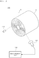
- FIG. 1 is a configuration diagram schematically illustrating an apparatus for measuring telescoping of a coil, according to an embodiment of the present disclosure.
- an apparatus 100 for measuring telescoping of a coil may include a laser generation unit 110, a camera unit 120, and a measurement unit 130.
- the laser generation unit 110 may output a laser at an arbitrary angle with respect to a coil A, wound on a transfer unit (not illustrated) transferred to a certain position, to generate a laser line B having a straight line on a lateral surface of the coil A.
- the camera unit 120 may be disposed at an arbitrary angle with respect to the laser line B, to obtain an image of the laser line.
- the laser generation unit 110 and the camera unit 120 may have an arbitrary angle, and as the angle increases, resolution of measuring telescoping of a coil may increase.
- FIG. 2 is a more detailed configuration diagram illustrating an apparatus for measuring telescoping of a coil, according to an embodiment of the present disclosure.
- a laser generation unit 110 of an apparatus 100 for measuring telescoping of a coil may include a plurality of line laser generators 111, 112, and 113, respectively generating a laser line.
- the plurality of line laser generators 111, 112, and 113 may be a first line laser generator 111, a second line laser generator 112, and a third line laser generator 113.
- Three (3) laser lines b1, b2, and b3 may be output at equal intervals.
- one (1) laser line may be interfered by a distorted signal to decrease a degree of recognition depending on an environment
- the three (3) laser lines may be restrictively used to increase the degree of recognition.
- the measurement unit 130 may secure end points of the three (3) laser lines to obtain a radius of a circle. When a value of the radius falls within a preset value, an object to be measured may be recognized as a coil.
- the camera unit 120 may include a plurality of cameras 121 and 122.
- the plurality of cameras 121 and 122 may be a first camera 121 and a second camera 122, respectively, and an absolute position of a coil shape may be known according to a stereo vision principle.
- An apparatus 100 for measuring telescoping of a coil may further include a transfer unit 140. Since a position of the transfer unit 140 is constant for each coil, the laser generation unit 110 may be formed at a fixed position. Since a center of the coil moves only in upward and downward directions according to weight of the coil, the laser line B may always pass through the center of the coil.
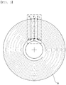
- FIG. 3 is a view illustrating telescoping of a coil measured by an apparatus for measuring telescoping of a coil, according to an embodiment of the present disclosure.
- the measurement unit 130 may apply the following principle with respect to a camera image of a laser line on a surface of the measured coil.
- the number of laser lines is three (3) in total.
- Three (3) lines of a cross-sectional view of the coil may be obtained from the three (3) laser lines, and end points of each of the lines may be obtained.
- the measurement unit 130 may obtain the end points of the three (3) laser lines, to obtain a radius of a circle, as illustrated in Equation 1 below.
- a value of the radius falls within a certain value, it may be recognized as a coil.
- End points of inner circle of coil of three 3 laser lines X 1 X 2 X 3
- End points of outer circle of coil of three 3 laser lines Y 1 Y 2 Y 3
- Effective diameter range 900 ⁇ R Y 1 Y 2 Y 3 ⁇ 2500 700 ⁇ r X 1 X 2 X 3 ⁇ 800
- r is a radius of an inner circle of a coil (mm)
- R is a radius of an outer circle of the coil (mm).
- points of each of the obtained lines by the measurement unit 130 may be calculated, as illustrated in Equation 2 below, by a formula of the inner circle and the outer circle of the coil.
- the center and radius of the coil that is, radii of the inner circle and the outer circle of the coil, may be found, and the difference between these values indicates the exact length of the telescope in the actual coil, that is, the thickness of the coil.
- FIG. 4 is a graph illustrating telescoping of a coil measured by an apparatus for measuring telescoping of a coil, according to an embodiment of the present disclosure.
- a measurement unit 130 may obtain a measured value of telescoping according to Equation 2 described above.
- the measurement unit 130 may average measured values of three (3) laser lines, or select a measured value of a laser line having a high light intensity, among the three (3) laser lines, to avoid measurement failure or distorted information and measure a more stable value.
- an apparatus less affected by an environment may be configured by making a fixed distance from the hot-rolled coil in a non-contact fixed type.
- a degree of telescoping of the hot-rolled coil may be measured only by a laser and a camera, work standards or prior problems of an operation according to a quantitative size may be grasped to obtain an effect of stabilizing coiling quality.
Landscapes
- Physics & Mathematics (AREA)
- General Physics & Mathematics (AREA)
- Engineering & Computer Science (AREA)
- Computer Vision & Pattern Recognition (AREA)
- Electromagnetism (AREA)
- Mechanical Engineering (AREA)
- Biochemistry (AREA)
- Life Sciences & Earth Sciences (AREA)
- Immunology (AREA)
- Pathology (AREA)
- Analytical Chemistry (AREA)
- Chemical & Material Sciences (AREA)
- Health & Medical Sciences (AREA)
- General Health & Medical Sciences (AREA)
- Computer Networks & Wireless Communication (AREA)
- Radar, Positioning & Navigation (AREA)
- Remote Sensing (AREA)
- Signal Processing (AREA)
- Length Measuring Devices By Optical Means (AREA)
- Winding, Rewinding, Material Storage Devices (AREA)
Abstract
Description
- The present disclosure relates to an apparatus for measuring telescoping of a coil.
- In general, when describing a coiling process in a hot-rolling line, a tip portion of a strip may be bent in a downward direction while passing through a pair of pinch rolls. The tip portion of the bent strip may be wrapped around a mandrel between the mandrel and a wrapper roll surrounding the mandrel. After a certain period of time has elapsed, the mandrel may expand in a circumferential direction, and tension may be applied between the pinch roll and the mandrel, to perform the coiling process.
- In such a coiler, if a material is shaken in a width direction while being wound, the material may not be wound in the same position during the coiling process, but the material may be wound in an arbitrary position in the width direction. In this manner, a step difference such as due to a telescope shape occurs in a coil wound in such an arbitrary position, which may be defined as telescoping. Such telescoping may have a major problem of lowering an error rate in a product due to defects such as stamping, folding, and the like, in processing the coil when the coiling process occurs.
- For the prior art, it can be easily understood with reference to
Korean Patent No. 10-1715497 - According to an embodiment of the present disclosure, there is provided an apparatus for measuring telescoping of a coil, which is a shape defect of the coil, after the coil is wounded by a coiler of a hot-rolling line and before the coil is transferred.
- According to an aspect of the present disclosure, an apparatus for measuring telescoping of a coil, according to an embodiment of the present disclosure, includes a laser generation unit generating at least one laser line output to a lateral surface of the coil and passing through a center of the coil; a camera unit capturing an image of the lateral surface of the coil, including the at least one laser line; and a measurement unit measuring a degree of telescoping of the coil along a length corresponding to the lateral surface of the coil, among lengths of the at least one laser line, from the image captured by the camera unit.
- According to an aspect of the present disclosure, an apparatus less affected by an environment and having an effect of stabilizing coiling quality may be provided.
-
-
FIG. 1 is a configuration diagram schematically illustrating an apparatus for measuring telescoping of a coil, according to an embodiment of the present disclosure. -
FIG. 2 is a more detailed configuration diagram illustrating an apparatus for measuring telescoping of a coil, according to an embodiment of the present disclosure. -
FIG. 3 is a view illustrating telescoping of a coil measured by an apparatus for measuring telescoping of a coil, according to an embodiment of the present disclosure. -
FIG. 4 is a graph illustrating telescoping of a coil measured by an apparatus for measuring telescoping of a coil, according to an embodiment of the present disclosure. - Hereinafter, embodiments will be described in detail with reference to the accompanying drawings so that those of ordinary skill in the art may easily implement the present disclosure.
-
FIG. 1 is a configuration diagram schematically illustrating an apparatus for measuring telescoping of a coil, according to an embodiment of the present disclosure. - Referring to
FIG. 1 , anapparatus 100 for measuring telescoping of a coil, according to an embodiment of the present disclosure, may include alaser generation unit 110, acamera unit 120, and ameasurement unit 130. - The
laser generation unit 110 may output a laser at an arbitrary angle with respect to a coil A, wound on a transfer unit (not illustrated) transferred to a certain position, to generate a laser line B having a straight line on a lateral surface of the coil A. - The
camera unit 120 may be disposed at an arbitrary angle with respect to the laser line B, to obtain an image of the laser line. - The
laser generation unit 110 and thecamera unit 120 may have an arbitrary angle, and as the angle increases, resolution of measuring telescoping of a coil may increase. -
FIG. 2 is a more detailed configuration diagram illustrating an apparatus for measuring telescoping of a coil, according to an embodiment of the present disclosure. - Referring to
FIGS. 1 and2 , alaser generation unit 110 of anapparatus 100 for measuring telescoping of a coil, according to an embodiment of the present disclosure, may include a plurality ofline laser generators line laser generators line laser generator 111, a secondline laser generator 112, and a thirdline laser generator 113. - Three (3) laser lines b1, b2, and b3 may be output at equal intervals.
- Since one (1) laser line may be interfered by a distorted signal to decrease a degree of recognition depending on an environment, the three (3) laser lines may be restrictively used to increase the degree of recognition.
- The
measurement unit 130 may secure end points of the three (3) laser lines to obtain a radius of a circle. When a value of the radius falls within a preset value, an object to be measured may be recognized as a coil. - The
camera unit 120 may include a plurality ofcameras cameras first camera 121 and asecond camera 122, respectively, and an absolute position of a coil shape may be known according to a stereo vision principle. - An
apparatus 100 for measuring telescoping of a coil, according to an embodiment of the present disclosure, may further include atransfer unit 140. Since a position of thetransfer unit 140 is constant for each coil, thelaser generation unit 110 may be formed at a fixed position. Since a center of the coil moves only in upward and downward directions according to weight of the coil, the laser line B may always pass through the center of the coil. -
FIG. 3 is a view illustrating telescoping of a coil measured by an apparatus for measuring telescoping of a coil, according to an embodiment of the present disclosure. - Referring to
FIG. 3 along withFIGS. 1 and2 , themeasurement unit 130 may apply the following principle with respect to a camera image of a laser line on a surface of the measured coil. - The number of laser lines is three (3) in total. Three (3) lines of a cross-sectional view of the coil may be obtained from the three (3) laser lines, and end points of each of the lines may be obtained.
- The
measurement unit 130 may obtain the end points of the three (3) laser lines, to obtain a radius of a circle, as illustrated in Equation 1 below. When a value of the radius falls within a certain value, it may be recognized as a coil.
- In addition, points of each of the obtained lines by the
measurement unit 130 may be calculated, as illustrated inEquation 2 below, by a formula of the inner circle and the outer circle of the coil. - From the calculated equation of each of the circles, the center and radius of the coil, that is, radii of the inner circle and the outer circle of the coil, may be found, and the difference between these values indicates the exact length of the telescope in the actual coil, that is, the thickness of the coil. By correcting the measured value of the laser line obtained by the actual camera to the calculated length, it may be possible to obtain even more precise measurement value.

-
FIG. 4 is a graph illustrating telescoping of a coil measured by an apparatus for measuring telescoping of a coil, according to an embodiment of the present disclosure. - Referring to
FIG. 4 , ameasurement unit 130 may obtain a measured value of telescoping according toEquation 2 described above. - The
measurement unit 130 may average measured values of three (3) laser lines, or select a measured value of a laser line having a high light intensity, among the three (3) laser lines, to avoid measurement failure or distorted information and measure a more stable value. - As described above, according to the present disclosure, in measuring telescoping of a hot-rolled coil, an apparatus less affected by an environment may be configured by making a fixed distance from the hot-rolled coil in a non-contact fixed type. In addition, since a degree of telescoping of the hot-rolled coil may be measured only by a laser and a camera, work standards or prior problems of an operation according to a quantitative size may be grasped to obtain an effect of stabilizing coiling quality.
- While example embodiments have been illustrated and described above, it will be apparent to those skilled in the art that modifications and variations could be made without departing from the scope of the present disclosure as defined by the appended claims.
Claims (8)
- An apparatus for measuring telescoping of a coil, comprising:a laser generation unit generating at least one laser line output to a lateral surface of the coil and passing through a center of the coil;a camera unit capturing an image of the lateral surface of the coil, including the at least one laser line; anda measurement unit measuring a degree of telescoping of the coil along a length corresponding to the lateral surface of the coil, among lengths of the at least one laser line, from the image captured by the camera unit.
- The apparatus of claim 1, wherein the laser generation unit comprises a plurality of line laser generators respectively outputting the at least one laser line.
- The apparatus of claim 2, wherein the laser generation unit comprises a first line laser generator, a second line laser generator, and a third line laser generator, respectively outputting the at least one laser line.
- The apparatus of claim 2, wherein the at least one laser line is output to the lateral surface of the coil at equal intervals.
- The apparatus of claim 1, wherein the camera unit comprises a plurality of cameras.
- The apparatus of claim 2, wherein the measurement unit recognizes both end points of a laser line overlapping an inner circle and an outer circle of the coil, among the at least one laser line, from the image captured by the camera unit, and recognizes a case in which a length between the both end points of the laser line is within a preset range, as the coil.
- The apparatus of claim 6, wherein the measurement unit measures the degree of telescoping of the coil according to an average value of the lengths between the both end points of the laser line, among the at least one laser line, or a length between both end points of a line having high light intensity in an image of the laser line.
- The apparatus of claim 1, further comprising a transfer unit transferring the coil to the same position.
Applications Claiming Priority (2)
| Application Number | Priority Date | Filing Date | Title |
|---|---|---|---|
| KR1020180101995A KR102043564B1 (en) | 2018-08-29 | 2018-08-29 | Measuring apparatus telescope of coil |
| PCT/KR2019/011073 WO2020046010A1 (en) | 2018-08-29 | 2019-08-29 | Apparatus for measuring telescoping of coil |
Publications (4)
| Publication Number | Publication Date |
|---|---|
| EP3845856A1 true EP3845856A1 (en) | 2021-07-07 |
| EP3845856A4 EP3845856A4 (en) | 2021-10-06 |
| EP3845856B1 EP3845856B1 (en) | 2024-03-13 |
| EP3845856C0 EP3845856C0 (en) | 2024-03-13 |
Family
ID=68577469
Family Applications (1)
| Application Number | Title | Priority Date | Filing Date |
|---|---|---|---|
| EP19855050.1A Active EP3845856B1 (en) | 2018-08-29 | 2019-08-29 | Apparatus for measuring telescoping of coil |
Country Status (5)
| Country | Link |
|---|---|
| EP (1) | EP3845856B1 (en) |
| JP (1) | JP7143509B2 (en) |
| KR (1) | KR102043564B1 (en) |
| CN (1) | CN112654833A (en) |
| WO (1) | WO2020046010A1 (en) |
Families Citing this family (6)
| Publication number | Priority date | Publication date | Assignee | Title |
|---|---|---|---|---|
| EP4086211B1 (en) | 2021-05-04 | 2023-08-23 | Comexi Group Industries, S.A.U | A film rewinder machine comprising a misalignment detector and misalignment detection method in a film rewinder machine |
| CN114441549B (en) * | 2021-12-31 | 2024-02-23 | 武汉钢铁有限公司 | Steel coil quality detection system and method |
| TWI806780B (en) * | 2022-09-28 | 2023-06-21 | 中國鋼鐵股份有限公司 | System and method for detecting and compensating depth |
| CN115647113A (en) * | 2022-10-09 | 2023-01-31 | 武汉钢铁有限公司 | A device and method for detecting coil core-pulling of a coiler |
| CN115625217B (en) * | 2022-10-27 | 2023-07-14 | 江苏沙钢集团有限公司 | A cold-rolled thickness on-line detection method and detection system |
| CN116164657A (en) * | 2023-01-10 | 2023-05-26 | 燕山大学 | Non-contact type hot rolled steel coil diameter and tower shape defect online detection method and system |
Family Cites Families (16)
| Publication number | Priority date | Publication date | Assignee | Title |
|---|---|---|---|---|
| JPS4872062A (en) * | 1971-12-29 | 1973-09-28 | ||
| JPS50107964A (en) * | 1974-01-31 | 1975-08-25 | ||
| JP2824141B2 (en) * | 1990-09-04 | 1998-11-11 | 日新製鋼株式会社 | Hot coil processing method |
| JP3110152B2 (en) * | 1992-05-14 | 2000-11-20 | 日新製鋼株式会社 | A device that detects the winding shape on the side of the coil |
| JP3155681B2 (en) * | 1995-06-30 | 2001-04-16 | 日本鋼管株式会社 | Coil winding shape measuring method, its measuring device, and coil winding shape monitoring device |
| KR100240985B1 (en) * | 1995-12-05 | 2000-03-02 | 이구택 | Apparatus for measuring telescope of steel coil and its method |
| KR19980026184A (en) * | 1996-10-08 | 1998-07-15 | 김종진 | Method for measuring side shape of winding coil moving on conveyor belt and device |
| JP2000055631A (en) * | 1998-08-13 | 2000-02-25 | Kawasaki Steel Corp | Coil winding measurement method |
| JP2003097923A (en) * | 2001-09-26 | 2003-04-03 | Kawasaki Steel Corp | Coil winding measurement method and device |
| KR20040020358A (en) * | 2002-08-30 | 2004-03-09 | 주식회사 포스코 | Device and method for telescope measurement for steel coil |
| KR100966544B1 (en) * | 2002-12-24 | 2010-06-29 | 주식회사 포스코 | Linear uneven defect detection device on coil surface |
| JP5974787B2 (en) * | 2012-09-28 | 2016-08-23 | Jfeスチール株式会社 | Edge defect detection method and edge defect detection apparatus for steel strip coil |
| KR102043459B1 (en) * | 2013-11-11 | 2019-11-11 | 삼성에스디아이 주식회사 | Web thickness measuring equipment and method |
| KR101581554B1 (en) * | 2014-05-28 | 2015-12-31 | 현대제철 주식회사 | Apparatus for measuring width of plate and mehtod thereof |
| CN104142127B (en) * | 2014-07-07 | 2017-12-05 | 北京福斯达轨道交通技术有限公司 | A kind of railway wheel diameter dynamic measurement device and method |
| KR101715497B1 (en) | 2015-08-19 | 2017-03-13 | 현대제철 주식회사 | Apparatus for measuring telescope of coil |
-
2018
- 2018-08-29 KR KR1020180101995A patent/KR102043564B1/en active Active
-
2019
- 2019-08-29 JP JP2021510227A patent/JP7143509B2/en active Active
- 2019-08-29 CN CN201980056713.0A patent/CN112654833A/en active Pending
- 2019-08-29 EP EP19855050.1A patent/EP3845856B1/en active Active
- 2019-08-29 WO PCT/KR2019/011073 patent/WO2020046010A1/en not_active Ceased
Also Published As
| Publication number | Publication date |
|---|---|
| EP3845856B1 (en) | 2024-03-13 |
| WO2020046010A1 (en) | 2020-03-05 |
| CN112654833A (en) | 2021-04-13 |
| KR102043564B1 (en) | 2019-11-12 |
| JP2021535382A (en) | 2021-12-16 |
| EP3845856C0 (en) | 2024-03-13 |
| EP3845856A4 (en) | 2021-10-06 |
| JP7143509B2 (en) | 2022-09-28 |
Similar Documents
| Publication | Publication Date | Title |
|---|---|---|
| EP3845856B1 (en) | Apparatus for measuring telescoping of coil | |
| EP0864847B1 (en) | Method of measuring the flatness of a moving metal sheet or of the front side of a coil | |
| US8459073B2 (en) | Method for measuring sheet material flatness and method for producing steel sheet using said measuring method | |
| WO2001035050A1 (en) | Method for measuring quality of bandlike body, method for suppressing camber, instrument for measuring quality of bandlike body, rolling machine, and trimming device | |
| CN112154112A (en) | Rewinding machine for producing paper rolls | |
| JP6772756B2 (en) | Steel plate shape straightening device, straightening method, and continuous pickling device for steel sheet | |
| EP3671113A1 (en) | Device and method for measuring kinks in coil | |
| JP7225880B2 (en) | Method for manufacturing hot-rolled coil | |
| KR100240985B1 (en) | Apparatus for measuring telescope of steel coil and its method | |
| EP1870174B1 (en) | Automatic control method of roll type pipe correction machine | |
| HU230935B1 (en) | Method and apparatus for straightening metal strip | |
| WO2014162666A1 (en) | Shape measuring device | |
| EP3657125A1 (en) | Device and method for determining variations in flatness when handling a material in the form of a strip | |
| CN114341753B (en) | Edge accumulation measurement | |
| RU2788830C1 (en) | Measurement of edge buildup | |
| JP2008107241A (en) | Method and apparatus for measuring plate shape of metal strip | |
| JP2710105B2 (en) | Method and apparatus for measuring shape of rolled foil wound on take-up reel | |
| JP2006234540A (en) | H-shape steel shape measurement method | |
| JPH07117364B2 (en) | Shape measurement method for cold rolled steel sheet | |
| EP4635643A1 (en) | Entry angle enlargement inhibiting device and method of manufacturing enameled wire | |
| RU2259245C1 (en) | Method of determining nonuniformity along roll gap of rolling mill, speed of metal in direction of movement of strip rolled under tension | |
| KR20160077257A (en) | Apparatus and method of controlling bending shape of strip wrapping in mandrel | |
| KR20040020358A (en) | Device and method for telescope measurement for steel coil | |
| JP2004020307A (en) | Method and apparatus for measuring coil thickness | |
| WO2024199806A1 (en) | Sensor and method for measuring a property of a strip |
Legal Events
| Date | Code | Title | Description |
|---|---|---|---|
| STAA | Information on the status of an ep patent application or granted ep patent |
Free format text: STATUS: THE INTERNATIONAL PUBLICATION HAS BEEN MADE |
|
| STAA | Information on the status of an ep patent application or granted ep patent |
Free format text: STATUS: REQUEST FOR EXAMINATION WAS MADE |
|
| PUAI | Public reference made under article 153(3) epc to a published international application that has entered the european phase |
Free format text: ORIGINAL CODE: 0009012 |
|
| 17P | Request for examination filed |
Effective date: 20210324 |
|
| AK | Designated contracting states |
Kind code of ref document: A1 Designated state(s): AL AT BE BG CH CY CZ DE DK EE ES FI FR GB GR HR HU IE IS IT LI LT LU LV MC MK MT NL NO PL PT RO RS SE SI SK SM TR |
|
| A4 | Supplementary search report drawn up and despatched |
Effective date: 20210903 |
|
| RIC1 | Information provided on ipc code assigned before grant |
Ipc: G01B 11/25 20060101ALI20210830BHEP Ipc: G01N 21/88 20060101ALI20210830BHEP Ipc: B21B 38/00 20060101ALI20210830BHEP Ipc: G01B 11/08 20060101ALI20210830BHEP Ipc: G01S 17/08 20060101ALI20210830BHEP Ipc: B21C 47/02 20060101ALI20210830BHEP Ipc: G01B 11/02 20060101ALI20210830BHEP Ipc: G01B 11/24 20060101AFI20210830BHEP |
|
| DAV | Request for validation of the european patent (deleted) | ||
| DAX | Request for extension of the european patent (deleted) | ||
| RAP3 | Party data changed (applicant data changed or rights of an application transferred) |
Owner name: POSCO HOLDINGS INC. |
|
| RAP1 | Party data changed (applicant data changed or rights of an application transferred) |
Owner name: POSCO CO., LTD |
|
| REG | Reference to a national code |
Ref country code: DE Ref legal event code: R079 Free format text: PREVIOUS MAIN CLASS: G01B0011240000 Ipc: G01B0011250000 Ref document number: 602019048374 Country of ref document: DE |
|
| GRAP | Despatch of communication of intention to grant a patent |
Free format text: ORIGINAL CODE: EPIDOSNIGR1 |
|
| STAA | Information on the status of an ep patent application or granted ep patent |
Free format text: STATUS: GRANT OF PATENT IS INTENDED |
|
| RIC1 | Information provided on ipc code assigned before grant |
Ipc: B21C 51/00 20060101ALN20230928BHEP Ipc: G01B 11/08 20060101ALN20230928BHEP Ipc: G01N 21/952 20060101ALI20230928BHEP Ipc: G01N 21/88 20060101ALI20230928BHEP Ipc: B21C 47/06 20060101ALI20230928BHEP Ipc: G01B 11/25 20060101AFI20230928BHEP |
|
| INTG | Intention to grant announced |
Effective date: 20231017 |
|
| GRAS | Grant fee paid |
Free format text: ORIGINAL CODE: EPIDOSNIGR3 |
|
| GRAA | (expected) grant |
Free format text: ORIGINAL CODE: 0009210 |
|
| STAA | Information on the status of an ep patent application or granted ep patent |
Free format text: STATUS: THE PATENT HAS BEEN GRANTED |
|
| AK | Designated contracting states |
Kind code of ref document: B1 Designated state(s): AL AT BE BG CH CY CZ DE DK EE ES FI FR GB GR HR HU IE IS IT LI LT LU LV MC MK MT NL NO PL PT RO RS SE SI SK SM TR |
|
| REG | Reference to a national code |
Ref country code: GB Ref legal event code: FG4D |
|
| REG | Reference to a national code |
Ref country code: CH Ref legal event code: EP |
|
| REG | Reference to a national code |
Ref country code: DE Ref legal event code: R096 Ref document number: 602019048374 Country of ref document: DE |
|
| REG | Reference to a national code |
Ref country code: IE Ref legal event code: FG4D |
|
| U01 | Request for unitary effect filed |
Effective date: 20240408 |
|
| U07 | Unitary effect registered |
Designated state(s): AT BE BG DE DK EE FI FR IT LT LU LV MT NL PT SE SI Effective date: 20240416 |
|
| PG25 | Lapsed in a contracting state [announced via postgrant information from national office to epo] |
Ref country code: GR Free format text: LAPSE BECAUSE OF FAILURE TO SUBMIT A TRANSLATION OF THE DESCRIPTION OR TO PAY THE FEE WITHIN THE PRESCRIBED TIME-LIMIT Effective date: 20240614 |
|
| PG25 | Lapsed in a contracting state [announced via postgrant information from national office to epo] |
Ref country code: RS Free format text: LAPSE BECAUSE OF FAILURE TO SUBMIT A TRANSLATION OF THE DESCRIPTION OR TO PAY THE FEE WITHIN THE PRESCRIBED TIME-LIMIT Effective date: 20240613 Ref country code: HR Free format text: LAPSE BECAUSE OF FAILURE TO SUBMIT A TRANSLATION OF THE DESCRIPTION OR TO PAY THE FEE WITHIN THE PRESCRIBED TIME-LIMIT Effective date: 20240313 |
|
| PG25 | Lapsed in a contracting state [announced via postgrant information from national office to epo] |
Ref country code: ES Free format text: LAPSE BECAUSE OF FAILURE TO SUBMIT A TRANSLATION OF THE DESCRIPTION OR TO PAY THE FEE WITHIN THE PRESCRIBED TIME-LIMIT Effective date: 20240313 |
|
| PG25 | Lapsed in a contracting state [announced via postgrant information from national office to epo] |
Ref country code: RS Free format text: LAPSE BECAUSE OF FAILURE TO SUBMIT A TRANSLATION OF THE DESCRIPTION OR TO PAY THE FEE WITHIN THE PRESCRIBED TIME-LIMIT Effective date: 20240613 Ref country code: NO Free format text: LAPSE BECAUSE OF FAILURE TO SUBMIT A TRANSLATION OF THE DESCRIPTION OR TO PAY THE FEE WITHIN THE PRESCRIBED TIME-LIMIT Effective date: 20240613 Ref country code: HR Free format text: LAPSE BECAUSE OF FAILURE TO SUBMIT A TRANSLATION OF THE DESCRIPTION OR TO PAY THE FEE WITHIN THE PRESCRIBED TIME-LIMIT Effective date: 20240313 Ref country code: GR Free format text: LAPSE BECAUSE OF FAILURE TO SUBMIT A TRANSLATION OF THE DESCRIPTION OR TO PAY THE FEE WITHIN THE PRESCRIBED TIME-LIMIT Effective date: 20240614 Ref country code: ES Free format text: LAPSE BECAUSE OF FAILURE TO SUBMIT A TRANSLATION OF THE DESCRIPTION OR TO PAY THE FEE WITHIN THE PRESCRIBED TIME-LIMIT Effective date: 20240313 |
|
| U20 | Renewal fee for the european patent with unitary effect paid |
Year of fee payment: 6 Effective date: 20240829 |
|
| PG25 | Lapsed in a contracting state [announced via postgrant information from national office to epo] |
Ref country code: IS Free format text: LAPSE BECAUSE OF FAILURE TO SUBMIT A TRANSLATION OF THE DESCRIPTION OR TO PAY THE FEE WITHIN THE PRESCRIBED TIME-LIMIT Effective date: 20240713 |
|
| PG25 | Lapsed in a contracting state [announced via postgrant information from national office to epo] |
Ref country code: SM Free format text: LAPSE BECAUSE OF FAILURE TO SUBMIT A TRANSLATION OF THE DESCRIPTION OR TO PAY THE FEE WITHIN THE PRESCRIBED TIME-LIMIT Effective date: 20240313 |
|
| PG25 | Lapsed in a contracting state [announced via postgrant information from national office to epo] |
Ref country code: CZ Free format text: LAPSE BECAUSE OF FAILURE TO SUBMIT A TRANSLATION OF THE DESCRIPTION OR TO PAY THE FEE WITHIN THE PRESCRIBED TIME-LIMIT Effective date: 20240313 |
|
| PG25 | Lapsed in a contracting state [announced via postgrant information from national office to epo] |
Ref country code: PL Free format text: LAPSE BECAUSE OF FAILURE TO SUBMIT A TRANSLATION OF THE DESCRIPTION OR TO PAY THE FEE WITHIN THE PRESCRIBED TIME-LIMIT Effective date: 20240313 |
|
| PG25 | Lapsed in a contracting state [announced via postgrant information from national office to epo] |
Ref country code: SK Free format text: LAPSE BECAUSE OF FAILURE TO SUBMIT A TRANSLATION OF THE DESCRIPTION OR TO PAY THE FEE WITHIN THE PRESCRIBED TIME-LIMIT Effective date: 20240313 |
|
| PG25 | Lapsed in a contracting state [announced via postgrant information from national office to epo] |
Ref country code: SM Free format text: LAPSE BECAUSE OF FAILURE TO SUBMIT A TRANSLATION OF THE DESCRIPTION OR TO PAY THE FEE WITHIN THE PRESCRIBED TIME-LIMIT Effective date: 20240313 Ref country code: SK Free format text: LAPSE BECAUSE OF FAILURE TO SUBMIT A TRANSLATION OF THE DESCRIPTION OR TO PAY THE FEE WITHIN THE PRESCRIBED TIME-LIMIT Effective date: 20240313 Ref country code: RO Free format text: LAPSE BECAUSE OF FAILURE TO SUBMIT A TRANSLATION OF THE DESCRIPTION OR TO PAY THE FEE WITHIN THE PRESCRIBED TIME-LIMIT Effective date: 20240313 Ref country code: PL Free format text: LAPSE BECAUSE OF FAILURE TO SUBMIT A TRANSLATION OF THE DESCRIPTION OR TO PAY THE FEE WITHIN THE PRESCRIBED TIME-LIMIT Effective date: 20240313 Ref country code: IS Free format text: LAPSE BECAUSE OF FAILURE TO SUBMIT A TRANSLATION OF THE DESCRIPTION OR TO PAY THE FEE WITHIN THE PRESCRIBED TIME-LIMIT Effective date: 20240713 Ref country code: CZ Free format text: LAPSE BECAUSE OF FAILURE TO SUBMIT A TRANSLATION OF THE DESCRIPTION OR TO PAY THE FEE WITHIN THE PRESCRIBED TIME-LIMIT Effective date: 20240313 |
|
| REG | Reference to a national code |
Ref country code: DE Ref legal event code: R097 Ref document number: 602019048374 Country of ref document: DE |
|
| PLBE | No opposition filed within time limit |
Free format text: ORIGINAL CODE: 0009261 |
|
| STAA | Information on the status of an ep patent application or granted ep patent |
Free format text: STATUS: NO OPPOSITION FILED WITHIN TIME LIMIT |
|
| 26N | No opposition filed |
Effective date: 20241216 |
|
| REG | Reference to a national code |
Ref country code: CH Ref legal event code: PL |
|
| GBPC | Gb: european patent ceased through non-payment of renewal fee |
Effective date: 20240829 |
|
| PG25 | Lapsed in a contracting state [announced via postgrant information from national office to epo] |
Ref country code: CH Free format text: LAPSE BECAUSE OF NON-PAYMENT OF DUE FEES Effective date: 20240831 Ref country code: MC Free format text: LAPSE BECAUSE OF FAILURE TO SUBMIT A TRANSLATION OF THE DESCRIPTION OR TO PAY THE FEE WITHIN THE PRESCRIBED TIME-LIMIT Effective date: 20240313 |
|
| PG25 | Lapsed in a contracting state [announced via postgrant information from national office to epo] |
Ref country code: GB Free format text: LAPSE BECAUSE OF NON-PAYMENT OF DUE FEES Effective date: 20240829 |
|
| PG25 | Lapsed in a contracting state [announced via postgrant information from national office to epo] |
Ref country code: IE Free format text: LAPSE BECAUSE OF NON-PAYMENT OF DUE FEES Effective date: 20240829 |
|
| U20 | Renewal fee for the european patent with unitary effect paid |
Year of fee payment: 7 Effective date: 20250822 |
|
| PG25 | Lapsed in a contracting state [announced via postgrant information from national office to epo] |
Ref country code: CY Free format text: LAPSE BECAUSE OF FAILURE TO SUBMIT A TRANSLATION OF THE DESCRIPTION OR TO PAY THE FEE WITHIN THE PRESCRIBED TIME-LIMIT; INVALID AB INITIO Effective date: 20190829 |
|
| PG25 | Lapsed in a contracting state [announced via postgrant information from national office to epo] |
Ref country code: HU Free format text: LAPSE BECAUSE OF FAILURE TO SUBMIT A TRANSLATION OF THE DESCRIPTION OR TO PAY THE FEE WITHIN THE PRESCRIBED TIME-LIMIT; INVALID AB INITIO Effective date: 20190829 |