EP3845837A1 - A cooling device having waterproof drip tray - Google Patents
A cooling device having waterproof drip tray Download PDFInfo
- Publication number
- EP3845837A1 EP3845837A1 EP20210259.6A EP20210259A EP3845837A1 EP 3845837 A1 EP3845837 A1 EP 3845837A1 EP 20210259 A EP20210259 A EP 20210259A EP 3845837 A1 EP3845837 A1 EP 3845837A1
- Authority
- EP
- European Patent Office
- Prior art keywords
- drip tray
- lug
- compressor
- cooling device
- fastening means
- Prior art date
- Legal status (The legal status is an assumption and is not a legal conclusion. Google has not performed a legal analysis and makes no representation as to the accuracy of the status listed.)
- Withdrawn
Links
- 238000001816 cooling Methods 0.000 title claims abstract description 26
- XLYOFNOQVPJJNP-UHFFFAOYSA-N water Substances O XLYOFNOQVPJJNP-UHFFFAOYSA-N 0.000 claims abstract description 28
- 238000007789 sealing Methods 0.000 claims description 9
- 230000000063 preceeding effect Effects 0.000 claims 2
- 238000000034 method Methods 0.000 description 12
- 230000000694 effects Effects 0.000 description 4
- 239000002826 coolant Substances 0.000 description 3
- 230000003247 decreasing effect Effects 0.000 description 3
- 238000004519 manufacturing process Methods 0.000 description 2
- 230000015572 biosynthetic process Effects 0.000 description 1
- 230000005494 condensation Effects 0.000 description 1
- 238000009833 condensation Methods 0.000 description 1
- 230000007423 decrease Effects 0.000 description 1
- 230000001419 dependent effect Effects 0.000 description 1
- 238000001704 evaporation Methods 0.000 description 1
- 230000008020 evaporation Effects 0.000 description 1
- JEIPFZHSYJVQDO-UHFFFAOYSA-N iron(III) oxide Inorganic materials O=[Fe]O[Fe]=O JEIPFZHSYJVQDO-UHFFFAOYSA-N 0.000 description 1
- 238000009877 rendering Methods 0.000 description 1
Images


Classifications
-
- F—MECHANICAL ENGINEERING; LIGHTING; HEATING; WEAPONS; BLASTING
- F25—REFRIGERATION OR COOLING; COMBINED HEATING AND REFRIGERATION SYSTEMS; HEAT PUMP SYSTEMS; MANUFACTURE OR STORAGE OF ICE; LIQUEFACTION SOLIDIFICATION OF GASES
- F25D—REFRIGERATORS; COLD ROOMS; ICE-BOXES; COOLING OR FREEZING APPARATUS NOT OTHERWISE PROVIDED FOR
- F25D21/00—Defrosting; Preventing frosting; Removing condensed or defrost water
- F25D21/14—Collecting or removing condensed and defrost water; Drip trays
-
- F—MECHANICAL ENGINEERING; LIGHTING; HEATING; WEAPONS; BLASTING
- F25—REFRIGERATION OR COOLING; COMBINED HEATING AND REFRIGERATION SYSTEMS; HEAT PUMP SYSTEMS; MANUFACTURE OR STORAGE OF ICE; LIQUEFACTION SOLIDIFICATION OF GASES
- F25D—REFRIGERATORS; COLD ROOMS; ICE-BOXES; COOLING OR FREEZING APPARATUS NOT OTHERWISE PROVIDED FOR
- F25D2321/00—Details or arrangements for defrosting; Preventing frosting; Removing condensed or defrost water, not provided for in other groups of this subclass
- F25D2321/14—Collecting condense or defrost water; Removing condense or defrost water
- F25D2321/143—Collecting condense or defrost water; Removing condense or defrost water characterised by means to fix, clamp, or connect water pipes or evaporation trays
-
- F—MECHANICAL ENGINEERING; LIGHTING; HEATING; WEAPONS; BLASTING
- F25—REFRIGERATION OR COOLING; COMBINED HEATING AND REFRIGERATION SYSTEMS; HEAT PUMP SYSTEMS; MANUFACTURE OR STORAGE OF ICE; LIQUEFACTION SOLIDIFICATION OF GASES
- F25D—REFRIGERATORS; COLD ROOMS; ICE-BOXES; COOLING OR FREEZING APPARATUS NOT OTHERWISE PROVIDED FOR
- F25D2321/00—Details or arrangements for defrosting; Preventing frosting; Removing condensed or defrost water, not provided for in other groups of this subclass
- F25D2321/14—Collecting condense or defrost water; Removing condense or defrost water
- F25D2321/144—Collecting condense or defrost water; Removing condense or defrost water characterised by the construction of drip water collection pans
- F25D2321/1442—Collecting condense or defrost water; Removing condense or defrost water characterised by the construction of drip water collection pans outside a refrigerator
Definitions
- the present invention relates to a cooling device, in particular to a cooling device having waterproof drip tray assembly means.
- the present invention relates to a cooling device having a drip tray that enables the water ensuing from the defrost process to be collected.
- the defrost process is carried out in order to remove the frost, accumulating on the evaporator which in time affects the energy efficiency of the cooling device if left unattended.
- the water resulting from the defrost process is carried to a drip tray provided on or in close vicinity of the compressor.
- the heat resulting during the operation of the compressor is used to vaporize the water.
- the drip tray is placed on the compressor via clips, wherein the clips are provided on a lower surface of the drip tray.
- the assembly personnel place the drip tray on the compressor wherein the clips are inserted inside a bracket provided on the compressor.
- a problem with the state of the art is that the drip tray, once it is fixed on the compressor via a fastening means, remains on the compressor. The drip tray, if needed to be removed from the compressor, the assembly personnel needs to break the fastening means rendering the drip tray useless. Therefore, the manufacturing costs of the cooling device increases.
- Another problem with the state of the art is that the water discharge line carrying the water ensuing due to the defrost process move on the drip tray which causes the water discharged to pour over the fastening means via which the drip tray is attached onto the compressor. The water leaks via the opening provided for the fastening means and reaches compressor which in time causes formation of rust or even flooding of the environment wherein the cooling device is kept.
- EP3102898B1 A prior art publication in the technical field of the present invention may be referred to as EP3102898B1 among others, the document disclosing a cooling appliance having an evaporation tray.
- An objective of the present invention is to prevent or minimize the amount of drip trays scrapped during the assembly process which in turn decreases the manufacturing costs.
- Another objective of the present invention is to prevent water leakages.
- the method realized to achieve the aim of the present invention and disclosed in the first claim and the dependent claims comprises a cooling device.
- the cooling device comprises a compressor and an evaporator.
- the compressor compresses the coolant and pumps the coolant into the cooling cycle.
- a fan is provided to circulate the air inside the compartments of the cooling device by passing the air through the evaporator.
- the humidity in the air freezes on the surface of the evaporator forming a layer of frost.
- the frost layer gets thicker in time, decreasing energy efficiency of the cooling device. Therefore, the cooling devices perform defrost process on regular intervals.
- the water ensuing from the defrost process is collected inside a drip tray.
- the drip tray and the evaporator are connected via a water discharge line fluidly connecting the evaporator to the drip tray.
- the drip tray is placed onto the compressor.
- the compressor has a casing enclosing the operational parts of the compressor hermetically from the outer environment.
- a bracket is placed onto the casing of the compressor.
- the bracket is in the shape of a "U" profile and form a conduit upon being placed onto the compressor.
- the drip tray comprises an aperture through which the bracket passes through upon placing the drip tray onto the compressor.
- a fastening means is provided via which the drip tray is removable placed onto the compressor.
- the drip tray further comprises a lug wherein the lug is attached to the drip tray in a pivotable manner between a closed position and an open position. During the open position, the lug protrudes away from the drip tray. During the closed position, the lug is pivoted with respect to the drip tray and folds onto the drip tray.
- the fastening means is accommodated inside an opening. During the closed position, the lug encloses the fastening means and the opening thereby preventing leakage of water. During the closed position, the lug forms a flush surface with the drip tray. By means of the lug, water leakages are prevented.
- Another advantageous effect of using the lug is that the lug can releasably enclose the fastening means. By means of this, the assembly line workers can pivot the lug to the open position if the fastening means is not seated onto the bracket properly. As a result, scrapping of drip trays is decreased.
- the lug is produced as an integral part of the drip tray.
- the lug comprises a pair of clips.
- the clips engage with the fastening means locking the clips and therefore the lug onto the drip tray.
- the clips needed to be compressed or pressed should the user or the assembly line worker needs to change the position of the lug from closed position to the open position.
- ease of use is provided for the assembly line workers if they need to remove the drip tray from the compressor.
- the fastening means comprises a pair of slots.
- the pair of clips are inserted inside the said slots in the closed position of the lug.
- the drip tray is attached onto the compressor in an unmovable and robust manner.
- the lug comprises a sealing member.
- the sealing member is a gasket.
- the sealing member at least partially surrounds the lower surface of the lug in the closed position.
- a channel is provided around the fastening means into which the sealing member is seated thereby providing further waterproofness.
- the drip tray is removable placed onto the compressor minimizing the amount of drip trays scrapped during the assembly process.
- Another advantageous effect of the present invention is that the water leakages are prevented by means of the lug completely enclosing the fastening means and the opening wherein the fastening means is accommodated. Sealing member provides further waterproofness.
- the present invention relates to a cooling device comprising; a compressor (1), an evaporator, a bracket attached onto the compressor (1) forming a conduit in-between, a drip tray (2) to be placed onto the compressor (1) wherein the drip tray (2) is configured to be fluidly communicated with the evaporator via a water discharge line such that the water discharged through said water discharge line is collected into the drip tray (2), the drip tray (2) comprising a fastening means (3) via which the drip tray (2) is removable placed onto the compressor (1) via the conduit.
- the present invention relates to a cooling device (1), comprising the drip tray (2) wherein the drip tray (2) comprises; a lug (4) pivotable attached to the drip tray (2) between an open position during which the lug (4) protrudes away from the drip tray (2), and a closed position during which the lug (4) is folded over to the drip tray (2) releasably enclosing the fastening means (3).
- the drip tray (2) is used to collect the water ensuing from the defrost process. The water is transferred to the drip tray (2) via a water discharge line. The heat resulting from the operation of the compressor (1) is used to vaporize the water collected inside the drip tray (2).
- the drip tray (2) is removable attached onto the compressor (1) via the fastening means (3) provided on the drip tray (2).
- the fastening means is visible upon being placed onto the compressor (1).
- a cut out volume is provided on the drip tray (2) wherein the said cut out volume accommodates the fastening means (3).
- the drip tray (2) further comprises the lug (4).
- the lug (4) has two positions. During the open position, the lug (4) protrudes away from the drip tray (2). During the closed position, the lug (4) folds onto the drip tray (2) enclosing the said cut out volume and therefore the fastening means (3). During the closed position, the fastening means (3) and the cut out volume is hidden from view. During the open position, the fastening means (3) is visible and the user may activate the fastening means (3) if the drip tray (2) is needed to be removed from the compressor (1).
- the lug (4) encloses the fastening means (3) in a waterproof manner. Therefore, water leakages are prevented.
- Another advantageous effect provided by means of this invention is that the lug (4) can be changed towards the open position should the user or the assembly line workers need to remove the drip tray (2). By means of this, number of scrapped drip trays is reduced.
- the lug (4) is integral with the drip tray (2).
- the lug (4) being an integral part of the drip tray (2), structural strength is achieved.
- Another advantageous effect provided is that the drip tray (2) can be produced with a single mold, thereby decreasing costs.
- the lug (4) comprises a pair of clips (5) which upon being pressed or compressed releases the lug (4) from the drip tray (2).
- the clips (5) passes through the cut out accommodating the fastening means (3).
- the clips (5) provides a reliable and convenient method for changing the position of the lug (4) from closed to open.
- the fastening means (3) comprises a pair of slots (6) into which the pair of clips (5) are seated in the closed position.
- the slots (6) extend along the extension direction of the fastening means (3).
- the slots (6) accommodate the clips (5) in closed position of the log (4).
- the lug (4) comprises a sealing member (7), providing waterproofness in the closed position.
- the sealing member (7) extends along the periphery of the lug (4) and provides waterproofness for the lug (4).
Landscapes
- Engineering & Computer Science (AREA)
- Chemical & Material Sciences (AREA)
- Combustion & Propulsion (AREA)
- Physics & Mathematics (AREA)
- Mechanical Engineering (AREA)
- Thermal Sciences (AREA)
- General Engineering & Computer Science (AREA)
- Removal Of Water From Condensation And Defrosting (AREA)
Abstract
The present invention relates to a cooling device comprising; a compressor (1), an evaporator,a bracket attached onto the compressor (1) forming a conduit in-between, a drip tray (2) to be placed onto the compressor (1) wherein the drip tray (2) is configured to be fluidly communicated with the evaporator via a water discharge line such that the water discharged through said water discharge line is collected into the drip tray (2), the drip tray (2) comprising a fastening means (3) via which the drip tray (2) is removable placed onto the compressor (1) via the conduit.
Description
- The present invention relates to a cooling device, in particular to a cooling device having waterproof drip tray assembly means.
- The present invention relates to a cooling device having a drip tray that enables the water ensuing from the defrost process to be collected. In cooling devices, for example freezers and refrigerators, the defrost process is carried out in order to remove the frost, accumulating on the evaporator which in time affects the energy efficiency of the cooling device if left unattended. The water resulting from the defrost process is carried to a drip tray provided on or in close vicinity of the compressor. The heat resulting during the operation of the compressor is used to vaporize the water. In the state of the art embodiments, the drip tray is placed on the compressor via clips, wherein the clips are provided on a lower surface of the drip tray. The assembly personnel place the drip tray on the compressor wherein the clips are inserted inside a bracket provided on the compressor. A problem with the state of the art is that the drip tray, once it is fixed on the compressor via a fastening means, remains on the compressor. The drip tray, if needed to be removed from the compressor, the assembly personnel needs to break the fastening means rendering the drip tray useless. Therefore, the manufacturing costs of the cooling device increases. Another problem with the state of the art is that the water discharge line carrying the water ensuing due to the defrost process move on the drip tray which causes the water discharged to pour over the fastening means via which the drip tray is attached onto the compressor. The water leaks via the opening provided for the fastening means and reaches compressor which in time causes formation of rust or even flooding of the environment wherein the cooling device is kept.
- A prior art publication in the technical field of the present invention may be referred to as
US20110232314A1 among others, the document disclosing a cooling appliance having a condensation collection chamber. - A prior art publication in the technical field of the present invention may be referred to as
EP3102898B1 among others, the document disclosing a cooling appliance having an evaporation tray. - An objective of the present invention is to prevent or minimize the amount of drip trays scrapped during the assembly process which in turn decreases the manufacturing costs.
- Another objective of the present invention is to prevent water leakages.
- The method realized to achieve the aim of the present invention and disclosed in the first claim and the dependent claims comprises a cooling device. The cooling device comprises a compressor and an evaporator. The compressor compresses the coolant and pumps the coolant into the cooling cycle. As the coolant passes through the evaporator, it expands, absorbs heat thus cooling the surface of the evaporator. A fan is provided to circulate the air inside the compartments of the cooling device by passing the air through the evaporator. The humidity in the air freezes on the surface of the evaporator forming a layer of frost. The frost layer gets thicker in time, decreasing energy efficiency of the cooling device. Therefore, the cooling devices perform defrost process on regular intervals. The water ensuing from the defrost process is collected inside a drip tray. The drip tray and the evaporator are connected via a water discharge line fluidly connecting the evaporator to the drip tray. As a result, the water ensuing from the defrost process is collected inside the drip tray. The drip tray is placed onto the compressor. The compressor has a casing enclosing the operational parts of the compressor hermetically from the outer environment. A bracket is placed onto the casing of the compressor. The bracket is in the shape of a "U" profile and form a conduit upon being placed onto the compressor. The drip tray comprises an aperture through which the bracket passes through upon placing the drip tray onto the compressor. A fastening means is provided via which the drip tray is removable placed onto the compressor. The drip tray further comprises a lug wherein the lug is attached to the drip tray in a pivotable manner between a closed position and an open position. During the open position, the lug protrudes away from the drip tray. During the closed position, the lug is pivoted with respect to the drip tray and folds onto the drip tray. The fastening means is accommodated inside an opening. During the closed position, the lug encloses the fastening means and the opening thereby preventing leakage of water. During the closed position, the lug forms a flush surface with the drip tray. By means of the lug, water leakages are prevented. Another advantageous effect of using the lug is that the lug can releasably enclose the fastening means. By means of this, the assembly line workers can pivot the lug to the open position if the fastening means is not seated onto the bracket properly. As a result, scrapping of drip trays is decreased.
- In an embodiment of the invention, the lug is produced as an integral part of the drip tray. By this means, mold related costs improve and also a robust structure for the lug and the drip tray is achieved.
- In an embodiment of the invention, the lug comprises a pair of clips. As the position of the lug changes from open position to the closed position, the clips engage with the fastening means locking the clips and therefore the lug onto the drip tray. The clips needed to be compressed or pressed should the user or the assembly line worker needs to change the position of the lug from closed position to the open position. By means of the clips, ease of use is provided for the assembly line workers if they need to remove the drip tray from the compressor.
- In an embodiment of the invention, the fastening means comprises a pair of slots. The pair of clips are inserted inside the said slots in the closed position of the lug. By means of the slots and the clips, the drip tray is attached onto the compressor in an unmovable and robust manner.
- In an embodiment of the invention, the lug comprises a sealing member. In an embodiment the sealing member is a gasket. The sealing member at least partially surrounds the lower surface of the lug in the closed position. In an embodiment, a channel is provided around the fastening means into which the sealing member is seated thereby providing further waterproofness.
- By means of the present invention, the drip tray is removable placed onto the compressor minimizing the amount of drip trays scrapped during the assembly process.
- Another advantageous effect of the present invention is that the water leakages are prevented by means of the lug completely enclosing the fastening means and the opening wherein the fastening means is accommodated. Sealing member provides further waterproofness.
- The drawings are not meant to delimit the scope of protection as identified in the claims nor should they be referred to alone in an effort to interpret the scope identified in the claims without recourse to the technical disclosure in the description of the present invention.
-
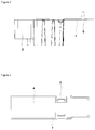
Figure 1 - is a cross sectional side view of the cooling device -
Figure 2 - is a top view of the drip tray -
Figure 3 - is a side view of the drip tray -
Figure 4 - is an isolated view of the lug - The following numerals are assigned to different parts demonstrated in the drawings and referred to in the present detailed description of the invention:
- 1. Compressor
- 2. Drip tray
- 3. Fastening means
- 4. Lug
- 5. Clip
- 6. Slot
- 7. Sealing member
- The present invention relates to a cooling device comprising; a compressor (1), an evaporator,
a bracket attached onto the compressor (1) forming a conduit in-between, a drip tray (2) to be placed onto the compressor (1) wherein the drip tray (2) is configured to be fluidly communicated with the evaporator via a water discharge line such that the water discharged through said water discharge line is collected into the drip tray (2), the drip tray (2) comprising a fastening means (3) via which the drip tray (2) is removable placed onto the compressor (1) via the conduit. - The present invention relates to a cooling device (1), comprising the drip tray (2) wherein the drip tray (2) comprises; a lug (4) pivotable attached to the drip tray (2) between an open position during which the lug (4) protrudes away from the drip tray (2), and a closed position during which the lug (4) is folded over to the drip tray (2) releasably enclosing the fastening means (3). The drip tray (2) is used to collect the water ensuing from the defrost process. The water is transferred to the drip tray (2) via a water discharge line. The heat resulting from the operation of the compressor (1) is used to vaporize the water collected inside the drip tray (2). The drip tray (2) is removable attached onto the compressor (1) via the fastening means (3) provided on the drip tray (2). The fastening means is visible upon being placed onto the compressor (1). A cut out volume is provided on the drip tray (2) wherein the said cut out volume accommodates the fastening means (3). The drip tray (2) further comprises the lug (4). The lug (4) has two positions. During the open position, the lug (4) protrudes away from the drip tray (2). During the closed position, the lug (4) folds onto the drip tray (2) enclosing the said cut out volume and therefore the fastening means (3). During the closed position, the fastening means (3) and the cut out volume is hidden from view. During the open position, the fastening means (3) is visible and the user may activate the fastening means (3) if the drip tray (2) is needed to be removed from the compressor (1). During the closed position, the lug (4) encloses the fastening means (3) in a waterproof manner. Therefore, water leakages are prevented. Another advantageous effect provided by means of this invention is that the lug (4) can be changed towards the open position should the user or the assembly line workers need to remove the drip tray (2). By means of this, number of scrapped drip trays is reduced.
- In a preferred embodiment of the invention, the lug (4) is integral with the drip tray (2). By means of the lug (4) being an integral part of the drip tray (2), structural strength is achieved. Another advantageous effect provided is that the drip tray (2) can be produced with a single mold, thereby decreasing costs.
- In a preferred embodiment of the invention, the lug (4) comprises a pair of clips (5) which upon being pressed or compressed releases the lug (4) from the drip tray (2). The clips (5) passes through the cut out accommodating the fastening means (3). The clips (5) provides a reliable and convenient method for changing the position of the lug (4) from closed to open.
- In a preferred embodiment of the invention, the fastening means (3) comprises a pair of slots (6) into which the pair of clips (5) are seated in the closed position. The slots (6) extend along the extension direction of the fastening means (3). The slots (6) accommodate the clips (5) in closed position of the log (4).
- In a preferred embodiment of the invention, the lug (4) comprises a sealing member (7), providing waterproofness in the closed position. The sealing member (7) extends along the periphery of the lug (4) and provides waterproofness for the lug (4).
Claims (5)
- A cooling device comprising;
a compressor (1),
an evaporator,
a bracket attached onto the compressor (1) forming a conduit in-between,
a drip tray (2) to be placed onto the compressor (1) wherein the drip tray (2) is configured to be fluidly communicated with the evaporator via a water discharge line such that the water discharged through said water discharge line is collected into the drip tray (2), the drip tray (2) comprising a fastening means (3) via which the drip tray (2) is removable placed onto the compressor (1) via the conduit,
characterized in that
the drip tray (2) comprises;
a lug (4) pivotable attached to the drip tray (2) between an open position during which the lug (4) protrudes away from the drip tray (2), and a closed position during which the lug (4) is folded over to the drip tray (2) releasably enclosing the fastening means (3). - A cooling device (1) according to claim 1, characterized in that the lug (4) is integral with the drip tray (2).
- A cooling device (1) according to any of the preceeding claims, characterized in that the lug (4) comprises a pair of clips (5) which upon being pressed or compressed releases the lug (4) from the drip tray (2).
- A cooling device (1) according to claims 3, characterized in that the fastening means (3) comprises a pair of slots (6) into which the pair of clips (5) are seated in the closed position.
- A cooling device (1) according to any of the preceeding claims, characterized in that the lug (4) comprises a sealing member (7), providing waterproofness in the closed position.
Applications Claiming Priority (1)
| Application Number | Priority Date | Filing Date | Title |
|---|---|---|---|
| TR201919694 | 2019-12-10 |
Publications (1)
| Publication Number | Publication Date |
|---|---|
| EP3845837A1 true EP3845837A1 (en) | 2021-07-07 |
Family
ID=73642634
Family Applications (1)
| Application Number | Title | Priority Date | Filing Date |
|---|---|---|---|
| EP20210259.6A Withdrawn EP3845837A1 (en) | 2019-12-10 | 2020-11-27 | A cooling device having waterproof drip tray |
Country Status (1)
| Country | Link |
|---|---|
| EP (1) | EP3845837A1 (en) |
Citations (4)
| Publication number | Priority date | Publication date | Assignee | Title |
|---|---|---|---|---|
| US20110232314A1 (en) | 2008-12-18 | 2011-09-29 | BSH Bosch und Siemens Hausgeräte GmbH | Refrigeration device |
| CN202709611U (en) * | 2012-07-20 | 2013-01-30 | 合肥美的荣事达电冰箱有限公司 | Refrigerator and water pan |
| DE102014208118A1 (en) * | 2014-04-30 | 2015-11-05 | BSH Hausgeräte GmbH | Refrigerating appliance with an evaporation tray |
| EP3102898B1 (en) | 2014-02-03 | 2018-09-12 | Arçelik Anonim Sirketi | A cooling device comprising an evaporation tray |
-
2020
- 2020-11-27 EP EP20210259.6A patent/EP3845837A1/en not_active Withdrawn
Patent Citations (4)
| Publication number | Priority date | Publication date | Assignee | Title |
|---|---|---|---|---|
| US20110232314A1 (en) | 2008-12-18 | 2011-09-29 | BSH Bosch und Siemens Hausgeräte GmbH | Refrigeration device |
| CN202709611U (en) * | 2012-07-20 | 2013-01-30 | 合肥美的荣事达电冰箱有限公司 | Refrigerator and water pan |
| EP3102898B1 (en) | 2014-02-03 | 2018-09-12 | Arçelik Anonim Sirketi | A cooling device comprising an evaporation tray |
| DE102014208118A1 (en) * | 2014-04-30 | 2015-11-05 | BSH Hausgeräte GmbH | Refrigerating appliance with an evaporation tray |
Similar Documents
| Publication | Publication Date | Title |
|---|---|---|
| EP3037754B1 (en) | Refrigerator | |
| KR101841838B1 (en) | Showcase to be guarded against any dew on them | |
| WO2015165512A1 (en) | Refrigeration appliance having an anti-condensation arrangement | |
| EP1807662B1 (en) | A cooling device and a control method | |
| US2552345A (en) | Refrigerating apparatus | |
| JP6398076B2 (en) | refrigerator | |
| EP3798553B1 (en) | A cooling device having simplified drip tray assembly means | |
| EP3106796A1 (en) | Refrigerator and ice making method therefor | |
| CN102809252B (en) | Integrated-type cold storage refrigerator | |
| KR100274502B1 (en) | An apparatus for eliminating the pressure discrepancy between the inner and the outer of a refrigerator | |
| AU2020314014B2 (en) | Refrigerator | |
| CN211120182U (en) | Refrigerator with a door | |
| CN217110162U (en) | Refrigerator air duct plate | |
| CN109737678A (en) | Door body assembly and refrigerating plant | |
| KR200332882Y1 (en) | a vacuum releasing apparatus for a refrigerator | |
| JP2008122064A (en) | Frost preventing refrigerating machine and defrosting device for refrigerating machine | |
| WO2015185090A1 (en) | Refrigeration appliance compressor having an integrated water collection receptacle | |
| EP4137013A1 (en) | Open refrigerator display with cascade system for evaporation of condensation moisture | |
| JP4460971B2 (en) | Cooling storage | |
| KR101695437B1 (en) | Packaged evaporative condensing water chiller | |
| KR100586980B1 (en) | Refrigerator | |
| KR200492900Y1 (en) | Refrigerator | |
| KR100419154B1 (en) | Machine room structure of showcase for defrost evaporation | |
| KR20070028635A (en) | Door structure of refrigerator | |
| CN118946774A (en) | Refrigerator with water collector |
Legal Events
| Date | Code | Title | Description |
|---|---|---|---|
| STAA | Information on the status of an ep patent application or granted ep patent |
Free format text: STATUS: REQUEST FOR EXAMINATION WAS MADE |
|
| PUAI | Public reference made under article 153(3) epc to a published international application that has entered the european phase |
Free format text: ORIGINAL CODE: 0009012 |
|
| 17P | Request for examination filed |
Effective date: 20201127 |
|
| AK | Designated contracting states |
Kind code of ref document: A1 Designated state(s): AL AT BE BG CH CY CZ DE DK EE ES FI FR GB GR HR HU IE IS IT LI LT LU LV MC MK MT NL NO PL PT RO RS SE SI SK SM TR |
|
| STAA | Information on the status of an ep patent application or granted ep patent |
Free format text: STATUS: THE APPLICATION IS DEEMED TO BE WITHDRAWN |
|
| 18D | Application deemed to be withdrawn |
Effective date: 20220108 |