EP3102898B1 - A cooling device comprising an evaporation tray - Google Patents
A cooling device comprising an evaporation tray Download PDFInfo
- Publication number
- EP3102898B1 EP3102898B1 EP15701230.3A EP15701230A EP3102898B1 EP 3102898 B1 EP3102898 B1 EP 3102898B1 EP 15701230 A EP15701230 A EP 15701230A EP 3102898 B1 EP3102898 B1 EP 3102898B1
- Authority
- EP
- European Patent Office
- Prior art keywords
- shaft
- casing
- evaporation tray
- cooling device
- compressor
- Prior art date
- Legal status (The legal status is an assumption and is not a legal conclusion. Google has not performed a legal analysis and makes no representation as to the accuracy of the status listed.)
- Active
Links
Images



Classifications
-
- F—MECHANICAL ENGINEERING; LIGHTING; HEATING; WEAPONS; BLASTING
- F25—REFRIGERATION OR COOLING; COMBINED HEATING AND REFRIGERATION SYSTEMS; HEAT PUMP SYSTEMS; MANUFACTURE OR STORAGE OF ICE; LIQUEFACTION SOLIDIFICATION OF GASES
- F25D—REFRIGERATORS; COLD ROOMS; ICE-BOXES; COOLING OR FREEZING APPARATUS NOT OTHERWISE PROVIDED FOR
- F25D21/00—Defrosting; Preventing frosting; Removing condensed or defrost water
- F25D21/14—Collecting or removing condensed and defrost water; Drip trays
-
- F—MECHANICAL ENGINEERING; LIGHTING; HEATING; WEAPONS; BLASTING
- F25—REFRIGERATION OR COOLING; COMBINED HEATING AND REFRIGERATION SYSTEMS; HEAT PUMP SYSTEMS; MANUFACTURE OR STORAGE OF ICE; LIQUEFACTION SOLIDIFICATION OF GASES
- F25D—REFRIGERATORS; COLD ROOMS; ICE-BOXES; COOLING OR FREEZING APPARATUS NOT OTHERWISE PROVIDED FOR
- F25D2321/00—Details or arrangements for defrosting; Preventing frosting; Removing condensed or defrost water, not provided for in other groups of this subclass
- F25D2321/14—Collecting condense or defrost water; Removing condense or defrost water
- F25D2321/141—Removal by evaporation
- F25D2321/1411—Removal by evaporation using compressor heat
-
- F—MECHANICAL ENGINEERING; LIGHTING; HEATING; WEAPONS; BLASTING
- F25—REFRIGERATION OR COOLING; COMBINED HEATING AND REFRIGERATION SYSTEMS; HEAT PUMP SYSTEMS; MANUFACTURE OR STORAGE OF ICE; LIQUEFACTION SOLIDIFICATION OF GASES
- F25D—REFRIGERATORS; COLD ROOMS; ICE-BOXES; COOLING OR FREEZING APPARATUS NOT OTHERWISE PROVIDED FOR
- F25D2321/00—Details or arrangements for defrosting; Preventing frosting; Removing condensed or defrost water, not provided for in other groups of this subclass
- F25D2321/14—Collecting condense or defrost water; Removing condense or defrost water
- F25D2321/143—Collecting condense or defrost water; Removing condense or defrost water characterised by means to fix, clamp, or connect water pipes or evaporation trays
-
- F—MECHANICAL ENGINEERING; LIGHTING; HEATING; WEAPONS; BLASTING
- F25—REFRIGERATION OR COOLING; COMBINED HEATING AND REFRIGERATION SYSTEMS; HEAT PUMP SYSTEMS; MANUFACTURE OR STORAGE OF ICE; LIQUEFACTION SOLIDIFICATION OF GASES
- F25D—REFRIGERATORS; COLD ROOMS; ICE-BOXES; COOLING OR FREEZING APPARATUS NOT OTHERWISE PROVIDED FOR
- F25D2321/00—Details or arrangements for defrosting; Preventing frosting; Removing condensed or defrost water, not provided for in other groups of this subclass
- F25D2321/14—Collecting condense or defrost water; Removing condense or defrost water
- F25D2321/144—Collecting condense or defrost water; Removing condense or defrost water characterised by the construction of drip water collection pans
- F25D2321/1442—Collecting condense or defrost water; Removing condense or defrost water characterised by the construction of drip water collection pans outside a refrigerator
Definitions
- the present invention relates to a cooling device comprising an evaporation tray that enables evaporation of the defrost water.
- cooling devices for example refrigerators or freezers
- the defrost process is performed in order to defrost the frost formed on the refrigeration system.
- a container named as the evaporation tray is used wherein the melted water is collected and evaporated.
- the evaporation tray is placed on the compressor to provide energy saving and the water inside the evaporation tray is enabled to be evaporated by using the heat generated by the compressor while operating.
- the evaporation tray is seated on the compressor so that the evaporation efficiency is high and the evaporation tray is agitated by being affected by the vibrations generated during the operation of the compressor.
- the evaporation tray that is agitated non-resonantly with respect to the compressor causes unwanted rattling by contacting the compressor.
- the total noise level of the cooling device increases when the oscillations of the compressor and the vibrations of the evaporation tray are in resonance.
- compressors in different sizes are used in cooling devices in different sizes and the same evaporation tray cannot be used for compressor casings in different sizes since the evaporation tray is seated on the surface of the compressor. This situation necessitates the production of evaporation trays suitable for compressors in different sizes and causes increase in production costs.
- a cooling device having an evaporation tray is disclosed, which is suitable to be mounted to different types of compressors.
- a cooling device comprising an evaporation tray having a flexible base.
- German Utility Model DE 84 37 286 U1 discloses a compressor on top of which an evaporator tray is mounted.
- a shaft extends vertically upwards from the casing of the compressor with its end projecting through an opening in the tray, wherein a leaf spring is arranged between the end of the shaft and the upper side of the tray and presses the tray down towards the compressor.
- British Patent GB 1 376 953 discloses a similar arrangement in which an evaporator tray is pressed towards a compressor by a nut, a protective washer, and a sealing washer that are arranged at the end of a stud which extends from the compressor through the bottom of the tray.
- the aim of the present invention is the realization of a cooling device that comprises a single type of evaporation tray that is suitable to be utilized with different types of compressors and wherein the total noise level is decreased.
- the noise level is prevented from increasing by transferring the oscillations generated while the compressor operates to the evaporation tray. Furthermore, the distance of the evaporation tray to the casing can be adjusted as desired by means of the nut and the evaporation tray is enabled to be used on compressors in different sizes.
- the shaft is mounted to the casing by screws without requiring changes in the production molds.
- connection is provided for compressors in any size.
- connection is maintained by adhering the shaft on the casing.
- the shaft is mounted without making alterations in the available products and thus the noise level is decreased.
- the shaft is produced with the casing as a single piece.
- the number of parts used is decreased and the noise generated at joints of the parts is prevented.
- a sealing member is used in order to prevent water from leaking between the shaft and the opening.
- the compressor is prevented from malfunctioning due to the water leaking through the opening - shaft cavity when the amount of condensed water increases.
- a second spring is used, that is fitted over the shaft, situated between the opening and the nut, in order to prevent the vibrations transmitted by the shaft to the evaporation tray by means of the nut.
- the casing is joined with the evaporation tray by a suspension-like method and the compressor vibrations are prevented from being transferred to the evaporation tray. Furthermore, by adjusting the compression rate of the first spring by the nut, the evaporation tray is mounted to compressors in different sizes.
- the cooling device (1) comprises a body (2), a compressor (3) that is situated inside the body (2), that performs the refrigeration cycle and that has a casing (4) covering the compressor (3), and an evaporation tray (5) that is disposed on the casing (4) and whereto the water condensed on the evaporator (not shown in the figures) is transferred.
- the water condensed on the evaporator after the defrost process is collected in the evaporation tray (5) that is disposed on the casing (4).
- the heat generated while the compressor (3) operates is transferred to the evaporation tray (5), enabling the water therein to be evaporated.
- the cooling device (1) of the present invention comprises a shaft (6) in form of an upright member that extends upwards vertically from the upper surface of the casing (4), a first spring (7) that is mounted by fitting around the shaft (6), an evaporation tray (5) that has an opening (8) through which the shaft (6) passes, and a nut (9) that is screwed to the end portion of the shaft (6) and that enables the first spring (7) to be compressed by applying pressure on the opening (8).
- the first spring (7) is mounted over the shaft (6) and the evaporation tray (5) is seated on the casing (4) by passing the shaft (6) through the opening (8).
- the first spring (7) is compressed by the nut (9) that is screwed to the screw threads formed on the upper end of the shaft (6) and the evaporation tray (5) is fixed to the casing (4).
- the vibrations generated while the compressor (3) operates are enabled to be dampened by the first spring (7).
- the evaporation tray (5) is enabled to be used with compressors (3) in different sizes by adjusting the compression rate of the first spring (7) by means of the nut (9).
- the shaft (6) is fixed on the casing (4) by means of screws.
- screw threads are formed on the lower end of the shaft (6) and the shaft (6) is screwed into the screw hole bored on the casing (4).
- the shaft (6) is fixed on the casing (4) by means of adhesion.
- adhesion By means of this embodiment, it is not required to make alterations on the casing (4) and the shaft (6) is enabled to be used with compressors (3) in any size.
- the shaft (6) is produced as a single piece with the casing (4).
- the noise originating from joining the casing (4) with the shaft (6) is prevented and furthermore strength is increased.
- the cooling device (1) comprises a sealing member (10) that provides leak-proofing between the shaft (6) and the opening (8).
- a sealing member (10) that provides leak-proofing between the shaft (6) and the opening (8).
- water is prevented from leaking from the cavity between the shaft (6) and the opening (8) and from damaging the compressor (3) when a large amount of water is collected in the evaporation tray (5).
- the cooling device (1) comprises a second spring (11) that is situated between the nut (9) and the opening (8) and that applies pressure on the evaporation tray (5) from above by being fitted over the shaft (6).
- the vibrations generated while the compressor (3) operates which are transmitted to the evaporation tray (5) by the casing (4) are dampened by the first spring (7), the vibrations transmitted through the shaft (6) when the nut (9) contacts the opening (8) are dampened by the second spring (11).
- the nut (9) can be a flange nut or a cap nut/a flat cap nut.
- the compressor (3) vibrations are dampened by the first spring (7) before being transmitted to the evaporation tray (5) and the total noise level is decreased by preventing the evaporation tray (5) from vibrating/shaking.
- a uniform evaporation tray (5) that can be used in compressors (3) in different sizes is realized by means of the shaft (6) and the opening (8).
Landscapes
- Engineering & Computer Science (AREA)
- Chemical & Material Sciences (AREA)
- Combustion & Propulsion (AREA)
- Physics & Mathematics (AREA)
- Mechanical Engineering (AREA)
- Thermal Sciences (AREA)
- General Engineering & Computer Science (AREA)
- Removal Of Water From Condensation And Defrosting (AREA)
Description
- The present invention relates to a cooling device comprising an evaporation tray that enables evaporation of the defrost water. In cooling devices, for example refrigerators or freezers, the defrost process is performed in order to defrost the frost formed on the refrigeration system. In the defrost process, a container named as the evaporation tray is used wherein the melted water is collected and evaporated. In state of the art embodiments, the evaporation tray is placed on the compressor to provide energy saving and the water inside the evaporation tray is enabled to be evaporated by using the heat generated by the compressor while operating. In this embodiment, the evaporation tray is seated on the compressor so that the evaporation efficiency is high and the evaporation tray is agitated by being affected by the vibrations generated during the operation of the compressor. The evaporation tray that is agitated non-resonantly with respect to the compressor causes unwanted rattling by contacting the compressor. The total noise level of the cooling device increases when the oscillations of the compressor and the vibrations of the evaporation tray are in resonance. At the same time, compressors in different sizes are used in cooling devices in different sizes and the same evaporation tray cannot be used for compressor casings in different sizes since the evaporation tray is seated on the surface of the compressor. This situation necessitates the production of evaporation trays suitable for compressors in different sizes and causes increase in production costs.
- In the Patent Application No.
WO2010055076 , a cooling device having an evaporation tray is disclosed, which is suitable to be mounted to different types of compressors. - In the Patent Application No.
EP2159520 , a cooling device is disclosed comprising an evaporation tray having a flexible base. - German Utility Model
DE 84 37 286 U1 discloses a compressor on top of which an evaporator tray is mounted. A shaft extends vertically upwards from the casing of the compressor with its end projecting through an opening in the tray, wherein a leaf spring is arranged between the end of the shaft and the upper side of the tray and presses the tray down towards the compressor. - British Patent
GB 1 376 953 - The aim of the present invention is the realization of a cooling device that comprises a single type of evaporation tray that is suitable to be utilized with different types of compressors and wherein the total noise level is decreased.
- The cooling device realized in order to attain the aim of the present invention is disclosed in the
independent claim 1. - In the cooling device of the present invention, the noise level is prevented from increasing by transferring the oscillations generated while the compressor operates to the evaporation tray. Furthermore, the distance of the evaporation tray to the casing can be adjusted as desired by means of the nut and the evaporation tray is enabled to be used on compressors in different sizes.
- In an embodiment of the present invention, the shaft is mounted to the casing by screws without requiring changes in the production molds. By means of the shaft screwed to the screw hole bored on the casing, connection is provided for compressors in any size.
- In an embodiment of the present invention, the connection is maintained by adhering the shaft on the casing. In this embodiment, the shaft is mounted without making alterations in the available products and thus the noise level is decreased.
- In an embodiment of the present invention, the shaft is produced with the casing as a single piece. By means of this embodiment, the number of parts used is decreased and the noise generated at joints of the parts is prevented.
- In an embodiment of the present invention, a sealing member is used in order to prevent water from leaking between the shaft and the opening. Thus, the compressor is prevented from malfunctioning due to the water leaking through the opening - shaft cavity when the amount of condensed water increases.
- In an embodiment of the present invention, a second spring is used, that is fitted over the shaft, situated between the opening and the nut, in order to prevent the vibrations transmitted by the shaft to the evaporation tray by means of the nut. By means of this embodiment, the vibrations generated by the compressor while operating are dampened by the first spring and the second spring, and the noise level is decreased.
- By means of the present invention, the casing is joined with the evaporation tray by a suspension-like method and the compressor vibrations are prevented from being transferred to the evaporation tray. Furthermore, by adjusting the compression rate of the first spring by the nut, the evaporation tray is mounted to compressors in different sizes.
- The cooling device realized in order to attain the aim of the present invention is illustrated in the attached figures, where:
-
Figure 1 - is the sideways schematic view of a cooling device. -
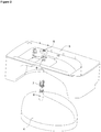
Figure 2 - is the exploded view of the casing and the evaporation tray related to an embodiment. -
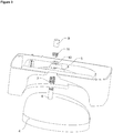
Figure 3 - is the exploded view of the casing and the evaporation tray related to another embodiment. -
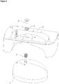
Figure 4 - is the exploded view of the casing and the evaporation tray related to an embodiment of the present invention. -
Figure 5 - is the perspective view of the casing and the evaporation tray related to an embodiment of the present invention. -
Figure 6 - is the perspective view of the casing and the evaporation tray related to another embodiment of the present invention. - The elements illustrated in the figures are numbered as follows:
- 1. Cooling device
- 2. Body
- 3. Compressor
- 4. Casing
- 5. Evaporation tray
- 6. Shaft
- 7. First spring
- 8. Opening
- 9. Nut
- 10. Sealing member
- 11. Second spring
- The cooling device (1) comprises a body (2), a compressor (3) that is situated inside the body (2), that performs the refrigeration cycle and that has a casing (4) covering the compressor (3), and an evaporation tray (5) that is disposed on the casing (4) and whereto the water condensed on the evaporator (not shown in the figures) is transferred.
- In the cooling device (1), the water condensed on the evaporator after the defrost process is collected in the evaporation tray (5) that is disposed on the casing (4). The heat generated while the compressor (3) operates is transferred to the evaporation tray (5), enabling the water therein to be evaporated.
- The cooling device (1) of the present invention comprises a shaft (6) in form of an upright member that extends upwards vertically from the upper surface of the casing (4), a first spring (7) that is mounted by fitting around the shaft (6), an evaporation tray (5) that has an opening (8) through which the shaft (6) passes, and a nut (9) that is screwed to the end portion of the shaft (6) and that enables the first spring (7) to be compressed by applying pressure on the opening (8). In the cooling device (1) of the present invention, the first spring (7) is mounted over the shaft (6) and the evaporation tray (5) is seated on the casing (4) by passing the shaft (6) through the opening (8). The first spring (7) is compressed by the nut (9) that is screwed to the screw threads formed on the upper end of the shaft (6) and the evaporation tray (5) is fixed to the casing (4). The vibrations generated while the compressor (3) operates are enabled to be dampened by the first spring (7). Furthermore, the evaporation tray (5) is enabled to be used with compressors (3) in different sizes by adjusting the compression rate of the first spring (7) by means of the nut (9).
- In an embodiment of the present invention, the shaft (6) is fixed on the casing (4) by means of screws. In this embodiment, screw threads are formed on the lower end of the shaft (6) and the shaft (6) is screwed into the screw hole bored on the casing (4).
- In an embodiment of the present invention, the shaft (6) is fixed on the casing (4) by means of adhesion. By means of this embodiment, it is not required to make alterations on the casing (4) and the shaft (6) is enabled to be used with compressors (3) in any size.
- In an embodiment of the present invention, the shaft (6) is produced as a single piece with the casing (4). In this embodiment, the noise originating from joining the casing (4) with the shaft (6) is prevented and furthermore strength is increased.
- In an embodiment of the present invention, the cooling device (1) comprises a sealing member (10) that provides leak-proofing between the shaft (6) and the opening (8). In this embodiment, water is prevented from leaking from the cavity between the shaft (6) and the opening (8) and from damaging the compressor (3) when a large amount of water is collected in the evaporation tray (5).
- In an embodiment of the present invention, the cooling device (1) comprises a second spring (11) that is situated between the nut (9) and the opening (8) and that applies pressure on the evaporation tray (5) from above by being fitted over the shaft (6). The vibrations generated while the compressor (3) operates which are transmitted to the evaporation tray (5) by the casing (4) are dampened by the first spring (7), the vibrations transmitted through the shaft (6) when the nut (9) contacts the opening (8) are dampened by the second spring (11).
- In an embodiment of the present invention, the nut (9) can be a flange nut or a cap nut/a flat cap nut.
- In the cooling device (1) of the present invention, the compressor (3) vibrations are dampened by the first spring (7) before being transmitted to the evaporation tray (5) and the total noise level is decreased by preventing the evaporation tray (5) from vibrating/shaking. A uniform evaporation tray (5) that can be used in compressors (3) in different sizes is realized by means of the shaft (6) and the opening (8).
Claims (6)
- A cooling device (1) comprising- a body (2),- a compressor (3) that is situated inside the body (2), that performs the refrigeration cycle and that has a casing (4) covering the compressor (3),- an evaporation tray (5) that is disposed on the casing (4) and whereto the water condensed on the evaporator is transferred,- a shaft (6) in form of an upright member that extends upwards vertically from the upper surface of the casing (4),- a first spring (7) that is mounted by fitting around the shaft (6),- an evaporation tray (5) that has an opening (8) through which the shaft (6) passes,characterized in that- the first spring (7) is arranged between the casing (4) and the evaporation tray (5)- a nut (9) is screwed to the end portion of the shaft (6) and enables the first spring (7) to be compressed by applying pressure on the opening (8).
- A cooling device (1) as in Claim 1, characterized in that the shaft (6) is fixed on the casing (4) by means of screws.
- A cooling device (1) as in Claim 1, characterized in that the shaft (6) is adhered on the casing (4).
- A cooling device (1) as in Claim 1, characterized in that the shaft (6) is produced as a single piece with the casing (4).
- A cooling device (1) as in any one of the above claims, characterized by a sealing member (10) that provides leak-proofing between the shaft (6) and the opening (8).
- A cooling device (1) as in any one of the above claims, characterized by a second spring (11) that is situated between the nut (9) and the opening (8) and that applies pressure on the evaporation tray (5) from above by being fitted over the shaft (6).
Applications Claiming Priority (2)
| Application Number | Priority Date | Filing Date | Title |
|---|---|---|---|
| TR201401201 | 2014-02-03 | ||
| PCT/EP2015/051644 WO2015113982A1 (en) | 2014-02-03 | 2015-01-28 | A cooling device comprising an evaporation tray |
Publications (2)
| Publication Number | Publication Date |
|---|---|
| EP3102898A1 EP3102898A1 (en) | 2016-12-14 |
| EP3102898B1 true EP3102898B1 (en) | 2018-09-12 |
Family
ID=52396709
Family Applications (1)
| Application Number | Title | Priority Date | Filing Date |
|---|---|---|---|
| EP15701230.3A Active EP3102898B1 (en) | 2014-02-03 | 2015-01-28 | A cooling device comprising an evaporation tray |
Country Status (3)
| Country | Link |
|---|---|
| EP (1) | EP3102898B1 (en) |
| TR (1) | TR201721791T3 (en) |
| WO (1) | WO2015113982A1 (en) |
Cited By (3)
| Publication number | Priority date | Publication date | Assignee | Title |
|---|---|---|---|---|
| EP3798553A1 (en) | 2019-09-27 | 2021-03-31 | Arçelik Anonim Sirketi | A cooling device having simplified drip tray assembly means |
| EP3845837A1 (en) | 2019-12-10 | 2021-07-07 | Arçelik Anonim Sirketi | A cooling device having waterproof drip tray |
| EP4575348A1 (en) * | 2023-12-21 | 2025-06-25 | BSH Electrodomésticos España, S.A. | Heat pump system for an electrical household appliance, and an electrical household appliance comprising a heat pump system |
Family Cites Families (3)
| Publication number | Priority date | Publication date | Assignee | Title |
|---|---|---|---|---|
| FR2129837B2 (en) * | 1971-03-16 | 1973-12-28 | Thomson Houston Hotchkis | |
| DE8437286U1 (en) * | 1984-12-20 | 1986-04-17 | Licentia Patent-Verwaltungs-Gmbh, 6000 Frankfurt | Condensate evaporation tray for a motor compressor |
| DE102008054936A1 (en) * | 2008-12-18 | 2010-06-24 | BSH Bosch und Siemens Hausgeräte GmbH | The refrigerator |
-
2015
- 2015-01-28 EP EP15701230.3A patent/EP3102898B1/en active Active
- 2015-01-28 TR TR2017/21791T patent/TR201721791T3/en unknown
- 2015-01-28 WO PCT/EP2015/051644 patent/WO2015113982A1/en not_active Ceased
Non-Patent Citations (1)
| Title |
|---|
| None * |
Cited By (3)
| Publication number | Priority date | Publication date | Assignee | Title |
|---|---|---|---|---|
| EP3798553A1 (en) | 2019-09-27 | 2021-03-31 | Arçelik Anonim Sirketi | A cooling device having simplified drip tray assembly means |
| EP3845837A1 (en) | 2019-12-10 | 2021-07-07 | Arçelik Anonim Sirketi | A cooling device having waterproof drip tray |
| EP4575348A1 (en) * | 2023-12-21 | 2025-06-25 | BSH Electrodomésticos España, S.A. | Heat pump system for an electrical household appliance, and an electrical household appliance comprising a heat pump system |
Also Published As
| Publication number | Publication date |
|---|---|
| TR201721791T3 (en) | 2018-01-22 |
| WO2015113982A1 (en) | 2015-08-06 |
| EP3102898A1 (en) | 2016-12-14 |
Similar Documents
| Publication | Publication Date | Title |
|---|---|---|
| US20160084567A1 (en) | Anchor assemblies and mounting kits for connecting door handles to doors of refrigerator appliances | |
| US20130294863A1 (en) | Floating fastener | |
| WO2015113982A1 (en) | A cooling device comprising an evaporation tray | |
| US10475562B2 (en) | Method for maintaining refrigeration unit and refrigeration unit | |
| CN204100706U (en) | A kind of floating sealing renovates blood plasma quick freezer | |
| CN104296498B (en) | A kind of floating sealing renovates blood plasma quick freezer | |
| CN106257169A (en) | Ice pan and the method for ice making for ice maker | |
| EP3327375B1 (en) | Accumulator fixing device for compressor, and air-conditioning apparatus including same | |
| US10921047B2 (en) | Home appliance device | |
| JP2017044282A (en) | Compressor support device | |
| CN205050253U (en) | Automatic vending machine modular refrigeration subassembly | |
| CN105352246A (en) | An adjustable water tray | |
| CN101341369A (en) | Refrigerant compressor | |
| CN204268777U (en) | Refrigerator | |
| KR101595629B1 (en) | Fan motor and fam motor assembly for refrigrator | |
| WO2015113981A1 (en) | A cooling device comprising an evaporation tray | |
| CN205119621U (en) | An adjustable water tray | |
| CN107270592A (en) | A kind of band fan micro-channel condenser assembly | |
| KR20150001509U (en) | Installation structure for chilled water unit a anti vibrator | |
| CN203796568U (en) | Shaft and rotor assembling structure of compressor | |
| KR100894017B1 (en) | Refrigerator fall prevention device | |
| CN203501636U (en) | Refrigerator | |
| CN204478720U (en) | A kind of wine-cooling machine | |
| CN111828448B (en) | Positioning device for vacuum heat insulation plate | |
| WO2015127997A1 (en) | Hermetic reciprocating mini compressor with reduced size |
Legal Events
| Date | Code | Title | Description |
|---|---|---|---|
| PUAI | Public reference made under article 153(3) epc to a published international application that has entered the european phase |
Free format text: ORIGINAL CODE: 0009012 |
|
| STAA | Information on the status of an ep patent application or granted ep patent |
Free format text: STATUS: REQUEST FOR EXAMINATION WAS MADE |
|
| 17P | Request for examination filed |
Effective date: 20160722 |
|
| AK | Designated contracting states |
Kind code of ref document: A1 Designated state(s): AL AT BE BG CH CY CZ DE DK EE ES FI FR GB GR HR HU IE IS IT LI LT LU LV MC MK MT NL NO PL PT RO RS SE SI SK SM TR |
|
| AX | Request for extension of the european patent |
Extension state: BA ME |
|
| DAX | Request for extension of the european patent (deleted) | ||
| GRAP | Despatch of communication of intention to grant a patent |
Free format text: ORIGINAL CODE: EPIDOSNIGR1 |
|
| STAA | Information on the status of an ep patent application or granted ep patent |
Free format text: STATUS: GRANT OF PATENT IS INTENDED |
|
| INTG | Intention to grant announced |
Effective date: 20180608 |
|
| GRAS | Grant fee paid |
Free format text: ORIGINAL CODE: EPIDOSNIGR3 |
|
| GRAA | (expected) grant |
Free format text: ORIGINAL CODE: 0009210 |
|
| STAA | Information on the status of an ep patent application or granted ep patent |
Free format text: STATUS: THE PATENT HAS BEEN GRANTED |
|
| AK | Designated contracting states |
Kind code of ref document: B1 Designated state(s): AL AT BE BG CH CY CZ DE DK EE ES FI FR GB GR HR HU IE IS IT LI LT LU LV MC MK MT NL NO PL PT RO RS SE SI SK SM TR |
|
| REG | Reference to a national code |
Ref country code: GB Ref legal event code: FG4D |
|
| REG | Reference to a national code |
Ref country code: CH Ref legal event code: EP |
|
| REG | Reference to a national code |
Ref country code: IE Ref legal event code: FG4D |
|
| REG | Reference to a national code |
Ref country code: DE Ref legal event code: R096 Ref document number: 602015016042 Country of ref document: DE |
|
| REG | Reference to a national code |
Ref country code: AT Ref legal event code: REF Ref document number: 1041078 Country of ref document: AT Kind code of ref document: T Effective date: 20181015 |
|
| REG | Reference to a national code |
Ref country code: NL Ref legal event code: MP Effective date: 20180912 |
|
| REG | Reference to a national code |
Ref country code: LT Ref legal event code: MG4D |
|
| PG25 | Lapsed in a contracting state [announced via postgrant information from national office to epo] |
Ref country code: FI Free format text: LAPSE BECAUSE OF FAILURE TO SUBMIT A TRANSLATION OF THE DESCRIPTION OR TO PAY THE FEE WITHIN THE PRESCRIBED TIME-LIMIT Effective date: 20180912 Ref country code: GR Free format text: LAPSE BECAUSE OF FAILURE TO SUBMIT A TRANSLATION OF THE DESCRIPTION OR TO PAY THE FEE WITHIN THE PRESCRIBED TIME-LIMIT Effective date: 20181213 Ref country code: RS Free format text: LAPSE BECAUSE OF FAILURE TO SUBMIT A TRANSLATION OF THE DESCRIPTION OR TO PAY THE FEE WITHIN THE PRESCRIBED TIME-LIMIT Effective date: 20180912 Ref country code: NO Free format text: LAPSE BECAUSE OF FAILURE TO SUBMIT A TRANSLATION OF THE DESCRIPTION OR TO PAY THE FEE WITHIN THE PRESCRIBED TIME-LIMIT Effective date: 20181212 Ref country code: SE Free format text: LAPSE BECAUSE OF FAILURE TO SUBMIT A TRANSLATION OF THE DESCRIPTION OR TO PAY THE FEE WITHIN THE PRESCRIBED TIME-LIMIT Effective date: 20180912 Ref country code: BG Free format text: LAPSE BECAUSE OF FAILURE TO SUBMIT A TRANSLATION OF THE DESCRIPTION OR TO PAY THE FEE WITHIN THE PRESCRIBED TIME-LIMIT Effective date: 20181212 Ref country code: LT Free format text: LAPSE BECAUSE OF FAILURE TO SUBMIT A TRANSLATION OF THE DESCRIPTION OR TO PAY THE FEE WITHIN THE PRESCRIBED TIME-LIMIT Effective date: 20180912 |
|
| PG25 | Lapsed in a contracting state [announced via postgrant information from national office to epo] |
Ref country code: AL Free format text: LAPSE BECAUSE OF FAILURE TO SUBMIT A TRANSLATION OF THE DESCRIPTION OR TO PAY THE FEE WITHIN THE PRESCRIBED TIME-LIMIT Effective date: 20180912 Ref country code: LV Free format text: LAPSE BECAUSE OF FAILURE TO SUBMIT A TRANSLATION OF THE DESCRIPTION OR TO PAY THE FEE WITHIN THE PRESCRIBED TIME-LIMIT Effective date: 20180912 Ref country code: HR Free format text: LAPSE BECAUSE OF FAILURE TO SUBMIT A TRANSLATION OF THE DESCRIPTION OR TO PAY THE FEE WITHIN THE PRESCRIBED TIME-LIMIT Effective date: 20180912 |
|
| REG | Reference to a national code |
Ref country code: AT Ref legal event code: MK05 Ref document number: 1041078 Country of ref document: AT Kind code of ref document: T Effective date: 20180912 |
|
| PG25 | Lapsed in a contracting state [announced via postgrant information from national office to epo] |
Ref country code: ES Free format text: LAPSE BECAUSE OF FAILURE TO SUBMIT A TRANSLATION OF THE DESCRIPTION OR TO PAY THE FEE WITHIN THE PRESCRIBED TIME-LIMIT Effective date: 20180912 Ref country code: NL Free format text: LAPSE BECAUSE OF FAILURE TO SUBMIT A TRANSLATION OF THE DESCRIPTION OR TO PAY THE FEE WITHIN THE PRESCRIBED TIME-LIMIT Effective date: 20180912 Ref country code: IS Free format text: LAPSE BECAUSE OF FAILURE TO SUBMIT A TRANSLATION OF THE DESCRIPTION OR TO PAY THE FEE WITHIN THE PRESCRIBED TIME-LIMIT Effective date: 20190112 Ref country code: PL Free format text: LAPSE BECAUSE OF FAILURE TO SUBMIT A TRANSLATION OF THE DESCRIPTION OR TO PAY THE FEE WITHIN THE PRESCRIBED TIME-LIMIT Effective date: 20180912 Ref country code: RO Free format text: LAPSE BECAUSE OF FAILURE TO SUBMIT A TRANSLATION OF THE DESCRIPTION OR TO PAY THE FEE WITHIN THE PRESCRIBED TIME-LIMIT Effective date: 20180912 Ref country code: CZ Free format text: LAPSE BECAUSE OF FAILURE TO SUBMIT A TRANSLATION OF THE DESCRIPTION OR TO PAY THE FEE WITHIN THE PRESCRIBED TIME-LIMIT Effective date: 20180912 Ref country code: IT Free format text: LAPSE BECAUSE OF FAILURE TO SUBMIT A TRANSLATION OF THE DESCRIPTION OR TO PAY THE FEE WITHIN THE PRESCRIBED TIME-LIMIT Effective date: 20180912 Ref country code: EE Free format text: LAPSE BECAUSE OF FAILURE TO SUBMIT A TRANSLATION OF THE DESCRIPTION OR TO PAY THE FEE WITHIN THE PRESCRIBED TIME-LIMIT Effective date: 20180912 Ref country code: AT Free format text: LAPSE BECAUSE OF FAILURE TO SUBMIT A TRANSLATION OF THE DESCRIPTION OR TO PAY THE FEE WITHIN THE PRESCRIBED TIME-LIMIT Effective date: 20180912 |
|
| PG25 | Lapsed in a contracting state [announced via postgrant information from national office to epo] |
Ref country code: SM Free format text: LAPSE BECAUSE OF FAILURE TO SUBMIT A TRANSLATION OF THE DESCRIPTION OR TO PAY THE FEE WITHIN THE PRESCRIBED TIME-LIMIT Effective date: 20180912 Ref country code: SK Free format text: LAPSE BECAUSE OF FAILURE TO SUBMIT A TRANSLATION OF THE DESCRIPTION OR TO PAY THE FEE WITHIN THE PRESCRIBED TIME-LIMIT Effective date: 20180912 Ref country code: PT Free format text: LAPSE BECAUSE OF FAILURE TO SUBMIT A TRANSLATION OF THE DESCRIPTION OR TO PAY THE FEE WITHIN THE PRESCRIBED TIME-LIMIT Effective date: 20190112 |
|
| REG | Reference to a national code |
Ref country code: DE Ref legal event code: R097 Ref document number: 602015016042 Country of ref document: DE |
|
| RAP2 | Party data changed (patent owner data changed or rights of a patent transferred) |
Owner name: ARCELIK ANONIM SIRKETI |
|
| PLBE | No opposition filed within time limit |
Free format text: ORIGINAL CODE: 0009261 |
|
| STAA | Information on the status of an ep patent application or granted ep patent |
Free format text: STATUS: NO OPPOSITION FILED WITHIN TIME LIMIT |
|
| PG25 | Lapsed in a contracting state [announced via postgrant information from national office to epo] |
Ref country code: DK Free format text: LAPSE BECAUSE OF FAILURE TO SUBMIT A TRANSLATION OF THE DESCRIPTION OR TO PAY THE FEE WITHIN THE PRESCRIBED TIME-LIMIT Effective date: 20180912 |
|
| 26N | No opposition filed |
Effective date: 20190613 |
|
| PG25 | Lapsed in a contracting state [announced via postgrant information from national office to epo] |
Ref country code: SI Free format text: LAPSE BECAUSE OF FAILURE TO SUBMIT A TRANSLATION OF THE DESCRIPTION OR TO PAY THE FEE WITHIN THE PRESCRIBED TIME-LIMIT Effective date: 20180912 Ref country code: MC Free format text: LAPSE BECAUSE OF FAILURE TO SUBMIT A TRANSLATION OF THE DESCRIPTION OR TO PAY THE FEE WITHIN THE PRESCRIBED TIME-LIMIT Effective date: 20180912 |
|
| REG | Reference to a national code |
Ref country code: CH Ref legal event code: PL |
|
| GBPC | Gb: european patent ceased through non-payment of renewal fee |
Effective date: 20190128 |
|
| PG25 | Lapsed in a contracting state [announced via postgrant information from national office to epo] |
Ref country code: LU Free format text: LAPSE BECAUSE OF NON-PAYMENT OF DUE FEES Effective date: 20190128 |
|
| REG | Reference to a national code |
Ref country code: BE Ref legal event code: MM Effective date: 20190131 |
|
| REG | Reference to a national code |
Ref country code: IE Ref legal event code: MM4A |
|
| PG25 | Lapsed in a contracting state [announced via postgrant information from national office to epo] |
Ref country code: FR Free format text: LAPSE BECAUSE OF NON-PAYMENT OF DUE FEES Effective date: 20190131 |
|
| PG25 | Lapsed in a contracting state [announced via postgrant information from national office to epo] |
Ref country code: BE Free format text: LAPSE BECAUSE OF NON-PAYMENT OF DUE FEES Effective date: 20190131 |
|
| PG25 | Lapsed in a contracting state [announced via postgrant information from national office to epo] |
Ref country code: GB Free format text: LAPSE BECAUSE OF NON-PAYMENT OF DUE FEES Effective date: 20190128 Ref country code: LI Free format text: LAPSE BECAUSE OF NON-PAYMENT OF DUE FEES Effective date: 20190131 Ref country code: CH Free format text: LAPSE BECAUSE OF NON-PAYMENT OF DUE FEES Effective date: 20190131 |
|
| PG25 | Lapsed in a contracting state [announced via postgrant information from national office to epo] |
Ref country code: IE Free format text: LAPSE BECAUSE OF NON-PAYMENT OF DUE FEES Effective date: 20190128 |
|
| PG25 | Lapsed in a contracting state [announced via postgrant information from national office to epo] |
Ref country code: MT Free format text: LAPSE BECAUSE OF NON-PAYMENT OF DUE FEES Effective date: 20190128 |
|
| PG25 | Lapsed in a contracting state [announced via postgrant information from national office to epo] |
Ref country code: CY Free format text: LAPSE BECAUSE OF FAILURE TO SUBMIT A TRANSLATION OF THE DESCRIPTION OR TO PAY THE FEE WITHIN THE PRESCRIBED TIME-LIMIT Effective date: 20180912 |
|
| PG25 | Lapsed in a contracting state [announced via postgrant information from national office to epo] |
Ref country code: HU Free format text: LAPSE BECAUSE OF FAILURE TO SUBMIT A TRANSLATION OF THE DESCRIPTION OR TO PAY THE FEE WITHIN THE PRESCRIBED TIME-LIMIT; INVALID AB INITIO Effective date: 20150128 |
|
| PG25 | Lapsed in a contracting state [announced via postgrant information from national office to epo] |
Ref country code: MK Free format text: LAPSE BECAUSE OF FAILURE TO SUBMIT A TRANSLATION OF THE DESCRIPTION OR TO PAY THE FEE WITHIN THE PRESCRIBED TIME-LIMIT Effective date: 20180912 |
|
| PGFP | Annual fee paid to national office [announced via postgrant information from national office to epo] |
Ref country code: DE Payment date: 20260121 Year of fee payment: 12 |
|
| PGFP | Annual fee paid to national office [announced via postgrant information from national office to epo] |
Ref country code: TR Payment date: 20260113 Year of fee payment: 12 |