EP3845799A1 - Vehicle lamp - Google Patents
Vehicle lamp Download PDFInfo
- Publication number
- EP3845799A1 EP3845799A1 EP19853387.9A EP19853387A EP3845799A1 EP 3845799 A1 EP3845799 A1 EP 3845799A1 EP 19853387 A EP19853387 A EP 19853387A EP 3845799 A1 EP3845799 A1 EP 3845799A1
- Authority
- EP
- European Patent Office
- Prior art keywords
- light
- distribution pattern
- optical lens
- incidence surface
- compound optical
- Prior art date
- Legal status (The legal status is an assumption and is not a legal conclusion. Google has not performed a legal analysis and makes no representation as to the accuracy of the status listed.)
- Granted
Links
Images


Classifications
-
- F—MECHANICAL ENGINEERING; LIGHTING; HEATING; WEAPONS; BLASTING
- F21—LIGHTING
- F21S—NON-PORTABLE LIGHTING DEVICES; SYSTEMS THEREOF; VEHICLE LIGHTING DEVICES SPECIALLY ADAPTED FOR VEHICLE EXTERIORS
- F21S41/00—Illuminating devices specially adapted for vehicle exteriors, e.g. headlamps
- F21S41/10—Illuminating devices specially adapted for vehicle exteriors, e.g. headlamps characterised by the light source
- F21S41/14—Illuminating devices specially adapted for vehicle exteriors, e.g. headlamps characterised by the light source characterised by the type of light source
- F21S41/141—Light emitting diodes [LED]
- F21S41/143—Light emitting diodes [LED] the main emission direction of the LED being parallel to the optical axis of the illuminating device
-
- F—MECHANICAL ENGINEERING; LIGHTING; HEATING; WEAPONS; BLASTING
- F21—LIGHTING
- F21S—NON-PORTABLE LIGHTING DEVICES; SYSTEMS THEREOF; VEHICLE LIGHTING DEVICES SPECIALLY ADAPTED FOR VEHICLE EXTERIORS
- F21S41/00—Illuminating devices specially adapted for vehicle exteriors, e.g. headlamps
- F21S41/10—Illuminating devices specially adapted for vehicle exteriors, e.g. headlamps characterised by the light source
- F21S41/14—Illuminating devices specially adapted for vehicle exteriors, e.g. headlamps characterised by the light source characterised by the type of light source
- F21S41/16—Laser light sources
-
- F—MECHANICAL ENGINEERING; LIGHTING; HEATING; WEAPONS; BLASTING
- F21—LIGHTING
- F21S—NON-PORTABLE LIGHTING DEVICES; SYSTEMS THEREOF; VEHICLE LIGHTING DEVICES SPECIALLY ADAPTED FOR VEHICLE EXTERIORS
- F21S41/00—Illuminating devices specially adapted for vehicle exteriors, e.g. headlamps
- F21S41/20—Illuminating devices specially adapted for vehicle exteriors, e.g. headlamps characterised by refractors, transparent cover plates, light guides or filters
- F21S41/25—Projection lenses
- F21S41/27—Thick lenses
-
- F—MECHANICAL ENGINEERING; LIGHTING; HEATING; WEAPONS; BLASTING
- F21—LIGHTING
- F21S—NON-PORTABLE LIGHTING DEVICES; SYSTEMS THEREOF; VEHICLE LIGHTING DEVICES SPECIALLY ADAPTED FOR VEHICLE EXTERIORS
- F21S41/00—Illuminating devices specially adapted for vehicle exteriors, e.g. headlamps
- F21S41/30—Illuminating devices specially adapted for vehicle exteriors, e.g. headlamps characterised by reflectors
- F21S41/32—Optical layout thereof
- F21S41/322—Optical layout thereof the reflector using total internal reflection
-
- F—MECHANICAL ENGINEERING; LIGHTING; HEATING; WEAPONS; BLASTING
- F21—LIGHTING
- F21S—NON-PORTABLE LIGHTING DEVICES; SYSTEMS THEREOF; VEHICLE LIGHTING DEVICES SPECIALLY ADAPTED FOR VEHICLE EXTERIORS
- F21S41/00—Illuminating devices specially adapted for vehicle exteriors, e.g. headlamps
- F21S41/40—Illuminating devices specially adapted for vehicle exteriors, e.g. headlamps characterised by screens, non-reflecting members, light-shielding members or fixed shades
- F21S41/43—Illuminating devices specially adapted for vehicle exteriors, e.g. headlamps characterised by screens, non-reflecting members, light-shielding members or fixed shades characterised by the shape thereof
-
- F—MECHANICAL ENGINEERING; LIGHTING; HEATING; WEAPONS; BLASTING
- F21—LIGHTING
- F21S—NON-PORTABLE LIGHTING DEVICES; SYSTEMS THEREOF; VEHICLE LIGHTING DEVICES SPECIALLY ADAPTED FOR VEHICLE EXTERIORS
- F21S45/00—Arrangements within vehicle lighting devices specially adapted for vehicle exteriors, for purposes other than emission or distribution of light
- F21S45/70—Prevention of harmful light leakage
-
- F—MECHANICAL ENGINEERING; LIGHTING; HEATING; WEAPONS; BLASTING
- F21—LIGHTING
- F21S—NON-PORTABLE LIGHTING DEVICES; SYSTEMS THEREOF; VEHICLE LIGHTING DEVICES SPECIALLY ADAPTED FOR VEHICLE EXTERIORS
- F21S41/00—Illuminating devices specially adapted for vehicle exteriors, e.g. headlamps
- F21S41/20—Illuminating devices specially adapted for vehicle exteriors, e.g. headlamps characterised by refractors, transparent cover plates, light guides or filters
- F21S41/29—Attachment thereof
- F21S41/295—Attachment thereof specially adapted to projection lenses
-
- F—MECHANICAL ENGINEERING; LIGHTING; HEATING; WEAPONS; BLASTING
- F21—LIGHTING
- F21S—NON-PORTABLE LIGHTING DEVICES; SYSTEMS THEREOF; VEHICLE LIGHTING DEVICES SPECIALLY ADAPTED FOR VEHICLE EXTERIORS
- F21S45/00—Arrangements within vehicle lighting devices specially adapted for vehicle exteriors, for purposes other than emission or distribution of light
- F21S45/40—Cooling of lighting devices
- F21S45/47—Passive cooling, e.g. using fins, thermal conductive elements or openings
-
- F—MECHANICAL ENGINEERING; LIGHTING; HEATING; WEAPONS; BLASTING
- F21—LIGHTING
- F21W—INDEXING SCHEME ASSOCIATED WITH SUBCLASSES F21K, F21L, F21S and F21V, RELATING TO USES OR APPLICATIONS OF LIGHTING DEVICES OR SYSTEMS
- F21W2102/00—Exterior vehicle lighting devices for illuminating purposes
- F21W2102/10—Arrangement or contour of the emitted light
- F21W2102/13—Arrangement or contour of the emitted light for high-beam region or low-beam region
- F21W2102/135—Arrangement or contour of the emitted light for high-beam region or low-beam region the light having cut-off lines, i.e. clear borderlines between emitted regions and dark regions
-
- F—MECHANICAL ENGINEERING; LIGHTING; HEATING; WEAPONS; BLASTING
- F21—LIGHTING
- F21W—INDEXING SCHEME ASSOCIATED WITH SUBCLASSES F21K, F21L, F21S and F21V, RELATING TO USES OR APPLICATIONS OF LIGHTING DEVICES OR SYSTEMS
- F21W2102/00—Exterior vehicle lighting devices for illuminating purposes
- F21W2102/10—Arrangement or contour of the emitted light
- F21W2102/17—Arrangement or contour of the emitted light for regions other than high beam or low beam
- F21W2102/18—Arrangement or contour of the emitted light for regions other than high beam or low beam for overhead signs
Definitions
- the present invention relates to a vehicle lamp.
- Patent Literature 1 discloses a vehicle lamp in which a low-beam light distribution pattern is formed by multiple light source units having different light distribution characteristics using compound optical lenses composed of shades and reflectors integrated with the lenses.
- an object of the disclosure is to provide a vehicle lamp using a compound optical lens that enables downsizing.
- a vehicle lamp is provided with a light source and a compound optical lens that emits light of the light source toward the front side;
- the compound optical lens is an integrally molded lens having an incidence surface, an emission surface, and a shade part, the incidence surface receiving light, the emission surface emitting the light from the incidence surface toward the front side, the shade part being formed between the incidence surface and the emission surface;
- the compound optical lens includes a first reflector surface that disposes above a top line of the shade part on the upper side of the incidence surface and reflects a light forming a first light distribution pattern toward the emission surface, and a second reflector surface that disposes below the top line on the lower side of the incidence surface and reflects a light forming a condensed-light distribution pattern toward the emission surface;
- the width of the first reflector surface is larger in a width of vehicle width direction at a position where the first reflector surface and the second reflector surface are adjacent to each other.
- a vehicle lamp using a compound optical lens that enables downsizing can be obtained.
- front and rear respectively refer to a “forward traveling direction” and a “backward traveling direction”
- top, bottom, “left”, and “right” refer to directions as seen from the driver of a vehicle 102, unless otherwise specified.
- top and bottom also respectively refer to the “top” and the “bottom” in the vertical direction
- left and right also respectively refer to the “left” and “right” in the horizontal direction.
- FIG. 1 is a plan view of a vehicle 102 including vehicle lamps of a first embodiment.
- the vehicle lamps of the first embodiment are vehicle headlights (101L, 101R) disposed on the front side of the vehicle 102, and, hereinafter, are simply referred to as vehicle lamps.
- a vehicle lamp of the present embodiment includes a housing (not illustrated) opened on the front side of the vehicle and an outer lens (not illustrated) attached to the housing so as to cover the opening.
- the vehicle lamp further includes a lamp unit 1 (see FIG. 2 ), etc., disposed in a lighting room composed of the housing and the outer lens.
- FIG. 2 is an exploded perspective view of a lamp unit 1 of the first embodiment.
- the lamp unit 1 includes a heatsink 10, a light source device 20 attached to the heatsink 10, an optical control member 30 disposed on the light source device 20, and a cover 40 that covers a portion of the optical control member 30.
- the heatsink 10 includes a base part 11 on which the light source device 20 is disposed; multiple heat radiating fins 12 disposed on the rear side of the base part 11 and arranged along the vehicle width direction; and two positioning pins 11A disposed on one side of the base part 11 in the vertical direction (bottom in FIG. 2 ), protruding toward the front side, and separated in the vehicle width direction.
- Two screw engagement holes 11B are formed in the base part 11 in the central area in the vehicle width direction and at positions separated in the vertical direction. Two screws N are screwed and fixed to the two screw engagement holes 11B so as to fasten together the light source device 20, the optical control member 30, and the cover 40, as described below.
- the heat radiating fins 12 extends vertically from the base part 11 to a second side (upper side in FIG. 2 ).
- the portion that extends vertically from the base part 11 (upper portion in FIG. 2 ) has a shape in which the base part 11 is recessed toward the rear side so as to house a connector connecting portion 23B of the light source device 20 as described below.
- the heatsink 10 is a heatsink 10 made of die-cast aluminum, but the heatsink 10 is not limited to this, and may be formed by using a metal or resin having high thermal conductivity.
- the light source device 20 includes a heat transfer member 21; a light source 22 disposed on the heat transfer member 21; and a connecting part 23 disposed on the heat transfer member 21 and having an opening 23A and a connector connecting portion 23B.
- the opening 23A is disposed at a position corresponding to the light source 22, and the connector connecting portion 23B is connected to an external connector.
- the connector connecting portion 23B is positioned on the second side (upper side in FIG. 2 ) in the vertical direction of the heat transfer member 21 such that a portion of the connector connecting portion 23B protrudes to the rear side of the heat transfer member 21.
- the protruding portion is positioned in a recess in the heat radiating fins 12 toward the rear side.
- the heat transfer member 21 is composed of an aluminum plate having a larger outer shape than that of the light source 22.
- the heat transfer member 21 may be composed of any material other than aluminum such as a metal or resin aluminum having high thermal conductivity.
- the heat transfer member 21 serves to increase the cooling efficiency of the light source 22 by efficiently transferring heat to the heatsink 10 while rapidly diffusing the heat generated at the light source 22 over a wide range.
- the light source 22 includes a substrate 22A having a light emitting region 22B that transmits light, and a light emitting chip (not illustrated) that is disposed on the back side of the substrate 22A and emits light for lighting the light emitting region 22B.
- the light source 22 is a laser diode light source (LD light source) using a laser diode chip (LD chip) as the light emitting chip, but alternatively a light-emitting-diode light source (LED light source) using an LED chip as the light emitting chip may be used.
- LD light source laser diode light source
- LED light source light-emitting-diode light source
- the light source 22 (light emitting chip) of the present embodiment has a lumbar cyan distribution or a similar distribution having a flat light emitting portion.
- the light source 22 be an LD light source.
- the connecting part 23 is a member formed by, for example, insert-molding using an electrically insulating resin having excellent heat resistance so as to internally accommodate electrical wiring (not illustrated) for electrically connecting the light source 22 and the external connector.
- electrical wiring (not illustrated)
- One end of the electrical wiring (not illustrated) is led out to the opening 23A to establish an electrical connection with the light source 22, and the other end of the electrical wiring (not illustrated) is led out into the connector connecting portion 23B to establish an electrical connection with an external connector.
- the light source device 20 includes two positioning holes 24A through which the two positioning pins 11A disposed on the base part 11 are passed, and two screw holes 24B disposed at positions corresponding to the screw engagement holes 11B formed in the base part 11.
- the light source device 20 can be fixed to the heatsink 10 by screws N while being positioned by the positioning pins 11A.
- the optical control member 30 includes a compound optical lens 31 that emits the light from the light source device 20 toward the front side, and a fixing part 32 for arranging the compound optical lens 31 on the light source device 20 and fixing the compound optical lens 31 to the heatsink 10 together with the light source device 20.
- the compound optical lens 31 and the fixing part 32 are integrally formed of a transparent resin (for example, acrylic resins and polycarbonate resins).
- the fixing part 32 includes a pair of leg portions 32A extending toward the rear side from the left and right side surfaces (left and right side surfaces on the front side of the top line 31CA of a shade part 31C described below) that do not affect the optical control of the compound optical lens 31, and a base portion 32B for fixing provided so as to be connected to the pair of leg portions 32A.
- the base portion 32B includes a pair of positioning holes 32BA through which the pair of positioning pins 11A disposed on the base part 11 are passed, and a pair of screw holes 32BB disposed at positions corresponding to the screw engagement holes 11B formed in the base part 11.
- the base portion 32B is fixed together with the light source device 20 to the heatsink 10 by the screws N while being positioned by the positioning pins 11A.
- the connecting part 23 functions as a heat insulator disposed between the optical control member 30 and the heat transfer member 21.
- an acrylic resin having low heat resistance for example, a heat resistant temperature of approximately 100°C
- the cover 40 includes substantially cylindrical covering part 41 and flange parts 42.
- the covering part 41 is opened so as not to block an emission surface 31A that emits the light of the compound optical lens 31 and an incidence surface 31B (see FIGS. 8 and 10 described below) on which the light is incident, and covers the side surface of the compound optical lens 31.
- the flange parts 42 are positioned behind the covering part 41 so as to protrude outward from the covering part 41 and fixes the cover 40 to the heatsink 10 together with the optical control member 30 and the light source device 20.
- the covering part 41 has a pair of notches 41A, separated in the vehicle width direction, at the front edge so that the pair of leg portions 32A of the fixing part 32 of the compound optical lens 31 can be inserted from the rear edge side.
- a pair of flange parts 42 are disposed apart from each other, on one side in the vertical direction (lower side in FIG. 2 ) and on another side in the vertical direction (upper side in FIG. 2 ) with reference to the portions of the pair of notches 41A, to enable the insertion of the leg portions 32A into the notches 41A.
- the flange parts 42 have a pair of positioning holes 42A through which the pair of positioning pins 11A disposed on the base part 11 pass, on the flange part 42 on the one side in the vertical direction (lower side in FIG. 2 ), and a pair of screw holes 42B, one of which is formed on the one side in the vertical direction (lower side in FIG. 2 ) and another one of which is formed on the other side in the vertical direction (upper side in FIG. 2 ), at positions corresponding to the screw engagement holes 11B disposed on the base part 11.
- the flange parts 42 are fixed to the heatsink 10 together with the optical control member 30 and the light source device 20 by the screws N while being positioned with the positioning pins 11A.
- the cover 40 is for suppressing light leakage from a position other than the emission surface 31A of the compound optical lens 31, and in the present embodiment, the cover 40 is formed of an opaque resin that does not transmit light.
- the cover 40 may be formed of a transparent resin that allows light to pass through, and may have a colored layer that suppresses light transmission on the surface.
- the cover 40 may be omitted, and aluminum vapor deposition or the like may be performed on a portion of the compound optical lens 31 other than the incidence surface 31B and the emission surface 31A to provide the same function as the cover 40.
- FIG. 3 is a cross-sectional view of the compound optical lens 31 and is a cross-sectional view from the side surface taken along the lens optical axis Z in the vertical direction.
- FIG. 3 also schematically illustrates the light emitting region 22B of the light source 22.
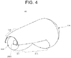
- FIG. 4 is a perspective view of the compound optical lens 31, in which the incidence surface 31B side of the compound optical lens 31 is visible.
- the compound optical lens 31 is an integrally molded lens having an incidence surface 31B, an emission surface 31A, and a shade part 31C.
- the incidence surface 31B receives light from the light source 22 (see FIG. 3 ).
- the emission surface 31A emits the light from the incidence surface 31B toward the front side and is a smoothly curved surface, without fine asperities, protruding toward the front side.
- the shade part 31C is formed between the incidence surface 31B and the emission surface 31A.
- the shade part 31C is formed so as to form a substantially triangular recess on the inner side of the compound optical lens 31 from the lower side in the vertical direction at a position between the incidence surface 31B and the emission surface 31A of the compound optical lens 31.
- the position of the apex of the triangular recess is set to be the top line 31CA that matches the shape of the cut-offline.
- the top line 31CA is formed so that the portion forming the upper side of the oblique cut-offline is positioned at the rear focal point or in the vicinity of the rear focal point of the emission surface 31A.
- the compound optical lens 31 has a semi-dome-shaped first reflector surface 31D having a free curved surface and a semi-dome-shaped second reflector surface 31E having a free curved surface.
- the first reflector surface 31D is formed on the upper side (upper side in the vertical direction) of the incidence surface 31B side of the top line 31CA of the shade part 31C, and reflects, toward the emission surface 31A, a light beam L1 that forms a first light distribution pattern of the low-beam light distribution pattern incident from the incidence surface 31B.
- the second reflector surface 31E is formed on the lower side (lower side in the vertical direction) of the incidence surface 31B side of the top line 31CA and reflects, toward the emission surface 31A, a light beam L2 that forms a condensed-light distribution pattern of the low-beam light distribution pattern incident from the incidence surface 31B.
- the first light distribution pattern is a diffused-light distribution pattern of the low-beam light distribution pattern, and therefore hereinafter may be referred to as the first diffused-light distribution pattern.
- the width of the first reflector surface 31D is larger than the width of the second reflector surface 31E in the vehicle width direction at the position where the first reflector surface 31D and the second reflector surface 31E are adjacent to each other so that the first diffused-light distribution pattern of the low-beam light distribution pattern can be satisfactorily formed.
- the first diffused-light distribution pattern and the condensed-light distribution pattern of the low-beam light distribution pattern can be formed with one compound optical lens 31, many light units 1 for forming the low-beam light distribution pattern is not needed, and the vehicle lamp can be downsized.
- the incidence surface 31B is a concave surface of which the overall shape is recessed toward the inner side of the compound optical lens 31.
- the incidence surface 31B has a convex surface 31BA that protrudes outward from the compound optical lens 31 and receives a light beam L3 forming a second light distribution pattern of the low-beam light distribution pattern in the central area.
- the second light distribution pattern is a medium-diffused-light distribution pattern of the low-beam light distribution pattern that is smaller than the first diffused-light distribution pattern of the low-beam light distribution pattern, and therefore hereinafter may be referred to as the second diffused-light distribution pattern.
- the convex surface 31BA has a substantially rectangular outer shape (square shape) and is formed so that the front focal point is located on the top line 31CA or in the vicinity of the top line 31CA, as illustrated in FIG. 3 .
- the light source 22 is positioned behind the convex surface 31BA so that the center of the convex surface 31BA and the light emission center of the light source 22 substantially coincide with each other when viewed in the vehicle width direction and the vertical direction, the light received by the convex surface 31BA is gradually condensed toward the top line 31CA and then gradually spreads from the front focal point toward the emission surface 31A, without great refraction, so as to form a satisfactory medium-diffused-light distribution pattern.
- the convex surface 31BA is designed to collect light in the vertical direction, but is designed to diffuse or spread in the horizontal direction.
- the second diffused light distribution pattern which is a medium level diffused-light distribution pattern (medium-diffused-light distribution pattern), multiplexed with the condensed-light distribution pattern and the first diffused light distribution pattern, is also formed. Therefore, the luminous intensity distribution of the low-beam light distribution pattern can be more satisfactory.
- the incidence surface 31B on the outer side of the convex surface 31BA has a shape that extends to the rear side, and the entire shape of the incidence surface 31B has a concave shape that is recessed toward the inner side of the compound optical lens 31, the light emitted from the light source 22 toward the front side can be incident on the compound optical lens 31 without loss, in consideration of the spread of the light.
- the rear focal point of the overall shape of the incidence surface 31B which is the concave surface recessed toward the inner side of the compound optical lens 31, substantially coincides with the rear focal points of the first reflector surface 31D and the second reflector surface 31E, and these rear focal points substantially coincide with the light emission center of the light source 22.
- the emission surface 31A is formed to have a shape that causes a portion of the light beam L1 forming the first diffused-light distribution pattern (a lower portion in the present embodiment) to be incident above the cut-offline of the condensed-light distribution pattern and the second diffused-light distribution pattern.
- the curvature of the lower side of the emission surface 31A is smoothly adjusted so that the light is emitted upward by approximately 0.2 to 0.5 degrees relative to the lens optical axis Z.
- the light source 22 is disposed so as to emit light toward the front side, and the compound optical lens 31 utilizes the spread of the light, forms a diffused-light distribution pattern (first diffused-light distribution pattern) of the largest low-beam light distribution pattern with the light spreading to the upper side, forms a condensed-light distribution pattern of the low-beam light distribution pattern with the light spreading to the lower side, and forms a middle-diffused-light distribution pattern (second diffused-light distribution pattern) of the low-beam light distribution pattern with the light in the central area; therefore a satisfactory low-beam light distribution pattern can be formed without using many lamp units 1, and the vehicle lamp can be downsized.
- first diffused-light distribution pattern of the largest low-beam light distribution pattern with the light spreading to the upper side
- second diffused-light distribution pattern forms a middle-diffused-light distribution pattern of the low-beam light distribution pattern with the light in the central area
- the spectroscopic light of the condensed-light distribution pattern having a slight yellow tint and the spectroscopic light of the first diffused-light distribution pattern having a bluish tint are multiplexed so that the spectral color can be relaxed.
- a vehicle lamp of a second embodiment will now be described with reference to FIGS. 5 to 7 .
- the overall configuration of the lamp unit 1 is also the same in the second embodiment, and the only difference from the first embodiment is the compound optical lens 31. Therefore, the main differences will be described below, and description of the same points may be omitted.
- FIG. 5 is a cross-sectional view of the compound optical lens 31 of the present embodiment and is a cross-sectional view from the side surface taken along the lens optical axis Z in the vertical direction. Note that FIG. 5 also schematically illustrates the light emitting region 22B of the light source 22.
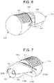
- FIG. 6 is a perspective view of the compound optical lens 31 in which that the emission surface 31A side of the present embodiment is visible.
- FIG. 7 is a perspective view of the compound optical lens 31 in which the incidence surface 31B side of the present embodiment is visible.
- the compound optical lens 31 of the present embodiment is an integrally molded lens having an incidence surface 31B, an emission surface 31A, and a shade part 31C.
- the incidence surface 31B receives light from the light source 22.
- the emission surface 31A emits the light from the incidence surface 31B toward the front side.
- the shade part 31C is formed between the incidence surface 31B and the emission surface 31A.
- the shade part 31C is also formed so as to form a substantially triangular recess on the inner side of the compound optical lens 31 from the lower side in the vertical direction at a position between the incidence surface 31B and the emission surface 31A of the compound optical lens 31.
- the position of the apex of the triangular recess is set to be the top line 31CA that matches the shape of the cut-offline.
- the compound optical lens 31 has a semi-dome-shaped first reflector surface 31D having a free curved surface and a semi-dome-shaped second reflector surface 31E having a free curved surface.
- the first reflector surface 31D is formed on the upper side (upper side in the vertical direction) of the incidence surface 31B side of the top line 31CA of the shade part 31C, and reflects, toward the emission surface 31A, a light beam that forms a first diffused-light distribution pattern of the low-beam light distribution pattern.
- the second reflector surface 31E is formed on the lower side (lower side in the vertical direction) of the incidence surface 31B side of the top line 31CA and reflects, toward the emission surface 31A, a light beam that forms a condensed-light distribution pattern of the low-beam light distribution pattern. Similar to above, the width of the first reflector surface 31D is larger than the width of the second reflector surface 31E in the vehicle width direction at the position where the first reflector surface 31D and the second reflector surface 31E are adjacent to each other.
- the shade part 31C Since the shade part 31C is formed so as to form a substantially triangular recess in the inner side of the compound optical lens 31, the shade part 31C has a rearward tilting surface 31CB that tilts rearward from the top line 31CA.
- a portion of the light reflected by the first reflector surface 31D, a portion of the light reflected by the second reflector surface 31E, and a portion of the direct light from the light source 22 are reflected by the rearward tilting surface 31CB, a portion of the reflected light is reflected by the surface on the front side above the top line 31CA and is emitted from the emission surface 31A toward the front side.
- Such light is not planned to be subjected to light distribution control by the emission surface 31A, and thus may be harmful light that is emitted into the lamp chamber and/or the vicinity of the vehicle.
- the compound optical lens 31 includes a light scatterer 31F formed on the emission surface 31A side of the top line 31CA of the shade part 31C in a section that reflects, toward the emission surface 31A, reflected light that is not planned to be subjected to light distribution control by the emission surface 31A.
- the light scatterer 31F is formed in a section of the compound optical lens 31 directly irradiated by the light reflected by the rearward tilting surface 31CB. In this way, as illustrated in FIG. 5 , light is scattered, and most of the scattered light becomes a light beam L4 emitted from the light scatterer 31F and is shielded and prevented from leaking outside by the cover 40 (see FIG. 2 ).
- a portion of the light scattered by the light scatterer 31F becomes a light beam L5 radiated from the emission surface 31A toward the front side.
- the intensity of the light beam L5 is significantly reduced, no harm is caused even when the light chamber and/or the vicinity of the vehicle are irradiated with the light beam L5.
- the light scatterer 31F is composed of fine asperities (for example, prisms) formed on the surface of the compound optical lens 31.
- the structure is not limited to this as long as light can be efficiently scattered.
- Another light scatterer may be disposed on the rearward tilting surface 31CB. In this way, the intensity of light that may be radiated to the lamp chamber and/or the vicinity of the vehicle can be further reduced.
- the compound optical lens 31 mainly controls the formation of the low-beam light distribution pattern.
- an overhead light distribution may be formed in addition to the low-beam light distribution pattern. The configuration for forming an overhead distribution light will be described below.
- the shade part 31C is formed so as to form a substantially triangular recess on the inner side of the compound optical lens 31, the shade part 31C has a forward tilting surface 31CC that tilts forward from the top line 31CA.
- a reflective surface 31G is formed on the compound optical lens 31.
- the reflective surface 31G reflects a portion of the direct light from the light source 22 toward at least a portion of the forward tilting surface 31CC.
- a light beam L6 reflected by the reflective surface 31G and further reflected by the forward tilting surface 31CC is emitted from the emission surface 31A as overhead distribution light.
- the reflective surface 31G is formed between the first reflector surface 31D and the light scatterer 31F on the upper side of the compound optical lens 31, and reflects a portion of the direct light from the light source 22 toward at least a section of the forward tilting surface 31CC.
- a reflection angle adjuster 31CCA for adjusting the reflection angle toward the emission surface 31A is disposed in a section of the forward tilting surface 31CC irradiated with the light reflected by the reflective surface 31G.
- the forward tilting surface 31CC be provided with the reflection angle adjuster 31CCA.
- the tilt state of the entire forward tilting surface 31CC may be set so that the light reflected by the reflective surface 31G is reflected toward the emission surface 31A at a reflection angle suitable for overhead light distribution.
- the first reflector surface 31D, the second reflector surface 31E, the forward tilting surface 31CC (or may be only the reflection angle adjuster 31CCA), and the reflective surface 31G are required to have a function of reflecting light, they may be colored with white or silver to increase the light reflectance.
- a satisfactory lamp unit 1 can be provided that can suppress harmful light, which may be generated due to the user of the compound optical lens 31, emitted to the lamp chamber and/or the vicinity of the vehicle, and can form overhead distribution light by the compound optical lens 31, which forms a low-beam light distribution pattern.
- a vehicle lamp of a third embodiment will now be described with reference to FIGS. 8 to 14 .
- the overall configuration of the lamp unit 1 is also the same in the third embodiment, and the only difference from the first and second embodiments is the compound optical lens 31. Therefore, the main differences will be described below, and description of the same points may be omitted.
- a vehicle lamp including a compound optical lens in which an incidence surface, an emission surface, and a shade part are integrally molded is known (for example, French Patent Publication No. 3010772 ).
- the compound optical lens collects the light incident to the incidence surface at the focal point of the emission surface, it is difficult to form a light distribution pattern having a spread or the like.
- the vehicle lamp of the third embodiment includes a light source and a compound optical lens.
- the compound optical lens includes an incidence surface on which light is incident; an emission surface that emits the light from the incidence surface toward the front side; a shade part formed between the incidence surface and the emission surface; a first reflector surface formed on the upper side of the incidence surface side and reflects the light forming a first light distribution pattern toward the emission surface; and a second reflector surface formed on the lower side of the incidence surface side and reflects the light forming a condensed-light distribution pattern toward the emission surface.
- the incidence surface on the vertical cross-section passing through the optical axis is formed such that the lower side of the incidence surface positioned below the light source is closer to the light source than the upper side of the incidence surface positioned above the light source.
- the vehicle lamp of the third embodiment it is also possible to facilitate the formation of a light distribution pattern having a spread.
- the compound optical lens 31 will now be described in detail with reference to FIGS. 8 to 14 .
- the overall features of the compound optical lens 31 will be described with reference to FIGS. 8 to 10 , and then the features of a portion of the compound optical lens 31 (the lower region of the incidence surface 31B) will be described in more detail with reference to FIGS. 12 to 14 .
- FIG. 8 is a cross-sectional view of the compound optical lens 31 of the present embodiment and is a cross-sectional view from the side surface taken along the lens optical axis Z in the vertical direction. Note that FIG. 8 also schematically illustrates the light emitting region 22B of the light source 22.
- FIG. 9 is a perspective view of the compound optical lens 31 in which that the emission surface 31A side of the present embodiment is visible.
- FIG. 10 is a perspective view of the compound optical lens 31 in which the incidence surface 31B side of the present embodiment is visible.
- the compound optical lens 31 of the present embodiment is an integrally molded lens having an incidence surface 31B, an emission surface 31A, and a shade part 31C.
- the incidence surface 31B receives light from the light source 22.
- the emission surface 31A emits the light from the incidence surface 31B toward the front side.
- the shade part 31C is formed between the incidence surface 31B and the emission surface 31A.
- the shade part 31C is formed so as to form a substantially triangular recess on the inner side of the compound optical lens 31 from the lower side in the vertical direction at a position between the incidence surface 31B and the emission surface 31A of the compound optical lens 31.
- the position of the apex of the triangular recess is set to be the top line 31CA that matches the shape of the cut-offline.
- the compound optical lens 31 has a semi-dome-shaped first reflector surface 31D having a free curved surface and a semi-dome-shaped second reflector surface 31E (total reflection surface) having a free curved surface.
- the first reflector surface 31D is formed on the upper side (upper side in the vertical direction) of the incidence surface 31B side of the top line 31CA of the shade part 31C, and reflects, toward the emission surface 31A, a light beam L1 that forms a first light distribution pattern of the low-beam light distribution pattern incident from the incidence surface 31B.
- the second reflector surface 31E is formed on the lower side (lower side in the vertical direction) of the incidence surface 31B side of the top line 31CA and reflects, toward the emission surface 31A, a light beam L2 that forms a condensed-light distribution pattern of the low-beam light distribution pattern incident from the incidence surface 31B.
- the incidence surface 31B is a concave surface of which the overall shape is recessed toward the inner side of the compound optical lens 31.
- the incidence surface 31B has a convex surface 31BA that protrudes outward from the compound optical lens 31 and receives a light beam L3 forming a second light distribution pattern of the low-beam light distribution pattern in the central area.
- the second light distribution pattern is a medium-diffused-light distribution pattern of the low-beam light distribution pattern that is smaller than the first diffused-light distribution pattern of the low-beam light distribution pattern, and therefore hereinafter may be referred to as the second diffused-light distribution pattern.
- the convex surface 31BA has a substantially rectangular outer shape (square shape) and is formed so that the front focal point is located on the top line 31CA or in the vicinity of the top line 31CA, as illustrated in FIG. 8 .
- the light source 22 is positioned behind the convex surface 31BA so that the center of the convex surface 31BA and the light emission center of the light source 22 substantially coincide with each other when viewed in the vehicle width direction and the vertical direction, the light received by the convex surface 31BA is gradually condensed toward the top line 31CA and then gradually spreads from the front focal point toward the emission surface 31A, without great refraction, so as to form a satisfactory medium-diffused-light distribution pattern.
- the convex surface 31BA is designed to collect light in the vertical direction, but is designed to diffuse or spread in the horizontal direction.
- the compound optical lens 31 includes a light scatterer 31F formed on the emission surface 31A side of the top line 31CA of the shade part 31C in a section that reflects, toward the emission surface 31A, reflected light that is not planned to be subjected to light distribution control by the emission surface 31A.
- the light scatterer 31F is formed in a section of the compound optical lens 31 directly irradiated by the light reflected by the rearward tilting surface 31CB. In this way, as illustrated in FIG. 8 , light is scattered, and most of the scattered light becomes a light beam L4 emitted from the light scatterer 31F and is shielded and prevented from leaking outside by the cover 40 (see FIG. 2 ).
- a portion of the light scattered by the light scatterer 31F becomes a light beam L5 radiated from the emission surface 31A toward the front side.
- the intensity of the light beam L5 is significantly reduced, no harm is caused even when the light chamber and/or the vicinity of the vehicle are irradiated with the light beam L5.
- the light scatterer 31F is composed of fine asperities (for example, prisms) formed on the surface of the compound optical lens 31.
- the structure is not limited to this as long as light can be efficiently scattered.
- Another light scatterer may be disposed on the rearward tilting surface 31CB. In this way, the intensity of light that may be radiated to the lamp chamber and/or the vicinity of the vehicle can be further reduced.
- the light scatterer 31F may be omitted.
- the compound optical lens 31 mainly controls the formation of the low-beam light distribution pattern.
- an overhead light distribution may be formed in addition to the low-beam light distribution pattern. The configuration for forming an overhead distribution light will be described below.
- the shade part 31C is formed so as to form a substantially triangular recess on the inner side of the compound optical lens 31, the shade part 31C has a forward tilting surface 31CC that tilts forward from the top line 31CA.
- a reflective surface 31G is formed on the compound optical lens 31.
- the reflective surface 31G reflects a portion of the direct light from the light source 22 toward at least a portion of the forward tilting surface 31CC.
- a light beam L6 reflected by the reflective surface 31G and further reflected by the forward tilting surface 31CC is emitted from the emission surface 31A as overhead distribution light.
- the reflective surface 31G is formed between the first reflector surface 31D and the light scatterer 31F on the upper side of the compound optical lens 31, and reflects a portion of the direct light from the light source 22 toward at least a section of the forward tilting surface 31CC.
- a reflection angle adjuster 31CCA for adjusting the reflection angle toward the emission surface 31A is disposed in a section of the forward tilting surface 31CC irradiated with the light reflected by the reflective surface 31G.
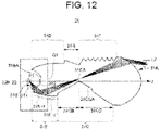
- FIG. 12 is a cross-sectional view of the compound optical lens 31 and is a cross-sectional view from the side surface taken along the lens optical axis Z in the vertical direction.
- FIG. 12 is the same cross-sectional view as that of FIG. 8 , but is an explanatory diagram illustrating in detail the optical path of the light beam L2 (see FIG. 8 ) forming the condensed-light distribution pattern of the low-beam light distribution pattern.
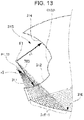
- FIG. 13 is an enlarged view of the Q1 portion in FIG. 12 .
- FIG. 14 is an explanatory view (cross-sectional view) of the case of a comparative example.
- the position of the light source 22 (the position of the light emission center) is denoted by P1.
- the lower region of the incidence surface 31B is a region on which the light reflected by the second reflector surface 31E is incident.
- the light reflected by the second reflector surface 31E includes the light beam L4 emitted from the light scatterer 31F and the light beam L2 forming the condensed-light distribution pattern of the low-beam light distribution pattern.
- the light scatterer 31F may be omitted.
- the light beam L4 is light that reaches a section corresponding to the light scatterer 31F (however, unlike the light scatterer 31F, the surface of this section is not provided with fine asperities).
- a region 31E-1 that reflects the light beam L2 is positioned closer to the light source 22 than a region 31E-2 that reflects the light beam L4, in the direction of the lens optical axis Z.
- the region below the light source 22 (or the light emitting region 22B) on the incidence surface 31B (hereinafter, referred to as "lower incidence surface 311") is formed such that light incident on the lower incidence surface 311 from the light emitting center is refracted, as illustrated in FIGS. 12 and 13 . That is, the light beam L2 is refracted at the incidence surface 31B and then reflected by the second reflector surface 31E.
- the lower incidence surface 311 is formed such that each light beam of the light refracted at the lower incidence surface 311 is focused at a point F1 (hereinafter, referred to as "virtual focal point F1") above the light source 22 when the light is traced in a direction opposite to the traveling direction of the light. That is, in FIG. 13 , each light beam of the light refracted is indicated by the dotted lines 700 when the light refracted at the lower incidence surface 311 is traced in a direction opposite to the traveling direction of the light. The dotted lines 700 intersect at the virtual focal point F1.
- the incidence surface 31B is formed such that the virtual focal point F1 is positioned above the light source 22 (see position P1) as illustrated in FIG. 13 .
- the position of the virtual focal point F1 is determined in accordance with the lower incidence surface 311.
- the lower incidence surface 311 is formed such that the virtual focal point F1 is positioned above the light source (see position P1)
- the lower incidence surface 311 is disposed closer to the light source 22 than a region 314 (see FIG. 13 ) above the convex surface 31BA of the incidence surface 31B. That is, when the region 314 is shaped like a sphere having a radius r1 centered on the light source 22 (see position P1), the distance r2 from the light source 22 (see position P1) to an arbitrary point in the lower incidence surface 311 is r1 or smaller.
- the optical control member 30' differs from the optical control member 30 according to the present embodiment in that the incidence surface 31B is replaced with an incidence surface 31B'.
- the incidence surface 31B' has a shape of a sphere (spherical surface) centered on the light source (see position P1) except for the convex surface 31BA.
- the light from the region below the incidence surface 31B' and reflected by the region of a second reflector surface 31E' near the light source 22 in the direction of the lens optical axis Z is reflected by the rearward tilting surface 31CB and travels toward the light scatterer 31F. That is, the light does not readily reach the emission surface 31A.
- the region of the second reflector surface 31E near the light source 22 in the direction of the lens optical axis Z is the region 31E-1 that reflects the light beam L2, i.e., the region 31E-1 that reflects the light that enters the emission surface 31A.
- the light beams reflected in the region of the second reflector surface 31E near the light source 22 in the direction of the lens optical axis Z can also be used as a light distribution pattern emitted from the emission surface 31A. That is, the utilization efficiency of the light increases.
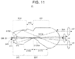
- the second reflector surface 31E can be designed as a reflective surface (free curved surface) having a focal point at the virtual focal point F1, and thus the structure can be easily designed.
- the second reflector surface 31E includes the region 31E-1 that reflects the light beam L2 and the region 31E-2 that reflects the light beam L4. According to the modified example, the second reflector surface 31E may include only the region 31E-1 that reflects the light beam L2.
- the compound optical lens 31 may be a compound optical lens that forms a high-beam light distribution pattern without the shade part 31C. Since it is possible to form a diffused distribution light pattern and a condensed-light distribution pattern of the high-beam light distribution pattern with one compound optical lens, the size of the vehicle lamp can be reduced.
- the shade function may be enhanced by applying aluminum vapor deposition, coloring, or the like to the surface of the shade part 31C.
- the entire lower incidence surface 311 is formed such that the light beams of the light refracted by the lower incidence surface 311 focuses at the virtual focal point F1 when the light is traced in a direction opposite to the traveling direction.
- the lower incidence surface 311 is not limited thereto.
- an upper portion of a region 312 of the lower incidence surface 311 may have a different design.
Landscapes
- Engineering & Computer Science (AREA)
- General Engineering & Computer Science (AREA)
- Physics & Mathematics (AREA)
- Optics & Photonics (AREA)
- Microelectronics & Electronic Packaging (AREA)
- Non-Portable Lighting Devices Or Systems Thereof (AREA)
Abstract
Description
- The present invention relates to a vehicle lamp.
-
Patent Literature 1 discloses a vehicle lamp in which a low-beam light distribution pattern is formed by multiple light source units having different light distribution characteristics using compound optical lenses composed of shades and reflectors integrated with the lenses. - PTL 1:
Japanese Unexamined Patent Publication No. 2004-241349 - There is a problem in that as the number of light source units increases, the vehicle lamps become larger.
- Therefore, an object of the disclosure is to provide a vehicle lamp using a compound optical lens that enables downsizing.
- According to one aspect of the present disclosure, a vehicle lamp is provided with a light source and a compound optical lens that emits light of the light source toward the front side; the compound optical lens is an integrally molded lens having an incidence surface, an emission surface, and a shade part, the incidence surface receiving light, the emission surface emitting the light from the incidence surface toward the front side, the shade part being formed between the incidence surface and the emission surface; the compound optical lens includes a first reflector surface that disposes above a top line of the shade part on the upper side of the incidence surface and reflects a light forming a first light distribution pattern toward the emission surface, and a second reflector surface that disposes below the top line on the lower side of the incidence surface and reflects a light forming a condensed-light distribution pattern toward the emission surface; the width of the first reflector surface is larger in a width of vehicle width direction at a position where the first reflector surface and the second reflector surface are adjacent to each other.
- According to the disclosure, a vehicle lamp using a compound optical lens that enables downsizing can be obtained.
-
- [
FIG. 1] FIG. 1 is a plan view of a vehicle including vehicle lamps of a first embodiment. - [
FIG. 2] FIG. 2 is an exploded perspective view of a lamp unit of the first embodiment. - [
FIG. 3] FIG. 3 is a cross-sectional view of a compound optical lens of the first embodiment. - [
FIG. 4] FIG. 4 is a perspective view of a compound optical lens of the first embodiment. - [
FIG. 5] FIG. 5 is a cross-sectional view of a compound optical lens of a second embodiment. - [
FIG. 6] FIG. 6 is a perspective view of the compound optical lens of the second embodiment with the side of an emission surface being visible. - [
FIG. 7] FIG. 7 is a perspective view of the compound optical lens of the second embodiment with the side of an incidence surface being visible. - [
FIG. 8] FIG. 8 is a cross-sectional view of a compound optical lens of a third embodiment. - [
FIG. 9] FIG. 9 is a perspective view of the compound optical lens of the third embodiment with the side of an emission surface being visible. - [
FIG. 10] FIG. 10 is a perspective view of the compound optical lens of the third embodiment with the side of an incidence surface being visible. - [
FIG. 11] FIG. 11 is a cross-sectional view of a compound optical lens according to a modification. - [
FIG. 12] FIG. 12 is a cross-sectional view of a compound optical lens for describing an optical path of light forming a condensed-light distribution pattern. - [
FIG. 13] FIG. 13 is an enlarged view of the Q1 portion inFIG. 12 . - [
FIG. 14] FIG. 14 is an explanatory view (cross-sectional view) of the case of a comparative example. - Embodiments will now be described with reference to the accompanying drawings. Note that the same numbers or reference signs denote the same elements throughout the description of the embodiments.
- In the embodiments and drawings, the terms "front" and "rear" respectively refer to a "forward traveling direction" and a "backward traveling direction", and the terms "top", "bottom", "left", and "right" refer to directions as seen from the driver of a
vehicle 102, unless otherwise specified. - Note that the terms "top" and "bottom" also respectively refer to the "top" and the "bottom" in the vertical direction, and the terms "left" and "right" also respectively refer to the "left" and "right" in the horizontal direction.
-
FIG. 1 is a plan view of avehicle 102 including vehicle lamps of a first embodiment. As illustrated inFIG. 1 , the vehicle lamps of the first embodiment are vehicle headlights (101L, 101R) disposed on the front side of thevehicle 102, and, hereinafter, are simply referred to as vehicle lamps. - A vehicle lamp of the present embodiment includes a housing (not illustrated) opened on the front side of the vehicle and an outer lens (not illustrated) attached to the housing so as to cover the opening. The vehicle lamp further includes a lamp unit 1 (see
FIG. 2 ), etc., disposed in a lighting room composed of the housing and the outer lens. -
FIG. 2 is an exploded perspective view of alamp unit 1 of the first embodiment. As illustrated inFIG. 2 , thelamp unit 1 includes a heatsink 10, a light source device 20 attached to the heatsink 10, anoptical control member 30 disposed on the light source device 20, and a cover 40 that covers a portion of theoptical control member 30. - The heatsink 10 includes a base part 11 on which the light source device 20 is disposed; multiple
heat radiating fins 12 disposed on the rear side of the base part 11 and arranged along the vehicle width direction; and two positioning pins 11A disposed on one side of the base part 11 in the vertical direction (bottom inFIG. 2 ), protruding toward the front side, and separated in the vehicle width direction. - Two screw engagement holes 11B are formed in the base part 11 in the central area in the vehicle width direction and at positions separated in the vertical direction. Two screws N are screwed and fixed to the two screw engagement holes 11B so as to fasten together the light source device 20, the
optical control member 30, and the cover 40, as described below. - The
heat radiating fins 12 extends vertically from the base part 11 to a second side (upper side inFIG. 2 ). The portion that extends vertically from the base part 11 (upper portion inFIG. 2 ) has a shape in which the base part 11 is recessed toward the rear side so as to house a connector connecting portion 23B of the light source device 20 as described below. - In the present embodiment, the heatsink 10 is a heatsink 10 made of die-cast aluminum, but the heatsink 10 is not limited to this, and may be formed by using a metal or resin having high thermal conductivity.
- The light source device 20 includes a heat transfer member 21; a light source 22 disposed on the heat transfer member 21; and a connecting part 23 disposed on the heat transfer member 21 and having an opening 23A and a connector connecting portion 23B. The opening 23A is disposed at a position corresponding to the light source 22, and the connector connecting portion 23B is connected to an external connector.
- Note that the connector connecting portion 23B is positioned on the second side (upper side in
FIG. 2 ) in the vertical direction of the heat transfer member 21 such that a portion of the connector connecting portion 23B protrudes to the rear side of the heat transfer member 21. As mentioned above, the protruding portion is positioned in a recess in theheat radiating fins 12 toward the rear side. - In the present embodiment, the heat transfer member 21 is composed of an aluminum plate having a larger outer shape than that of the light source 22. However, the heat transfer member 21 may be composed of any material other than aluminum such as a metal or resin aluminum having high thermal conductivity. The heat transfer member 21 serves to increase the cooling efficiency of the light source 22 by efficiently transferring heat to the heatsink 10 while rapidly diffusing the heat generated at the light source 22 over a wide range.
- The light source 22 includes a substrate 22A having a light emitting region 22B that transmits light, and a light emitting chip (not illustrated) that is disposed on the back side of the substrate 22A and emits light for lighting the light emitting region 22B. In the embodiment, the light source 22 is a laser diode light source (LD light source) using a laser diode chip (LD chip) as the light emitting chip, but alternatively a light-emitting-diode light source (LED light source) using an LED chip as the light emitting chip may be used.
- Note that the light source 22 (light emitting chip) of the present embodiment has a lumbar cyan distribution or a similar distribution having a flat light emitting portion.
- However, since it is easier to downsize a light source 22 that is an LD light source than one that is an LED light source, it is preferable that the light source 22 be an LD light source.
- The connecting part 23 is a member formed by, for example, insert-molding using an electrically insulating resin having excellent heat resistance so as to internally accommodate electrical wiring (not illustrated) for electrically connecting the light source 22 and the external connector. One end of the electrical wiring (not illustrated) is led out to the opening 23A to establish an electrical connection with the light source 22, and the other end of the electrical wiring (not illustrated) is led out into the connector connecting portion 23B to establish an electrical connection with an external connector.
- The light source device 20 includes two positioning holes 24A through which the two positioning pins 11A disposed on the base part 11 are passed, and two screw holes 24B disposed at positions corresponding to the screw engagement holes 11B formed in the base part 11. The light source device 20 can be fixed to the heatsink 10 by screws N while being positioned by the positioning pins 11A.
- The
optical control member 30 includes a compoundoptical lens 31 that emits the light from the light source device 20 toward the front side, and a fixing part 32 for arranging the compoundoptical lens 31 on the light source device 20 and fixing the compoundoptical lens 31 to the heatsink 10 together with the light source device 20. In theoptical control member 30, the compoundoptical lens 31 and the fixing part 32 are integrally formed of a transparent resin (for example, acrylic resins and polycarbonate resins). - The fixing part 32 includes a pair of leg portions 32A extending toward the rear side from the left and right side surfaces (left and right side surfaces on the front side of the top line 31CA of a
shade part 31C described below) that do not affect the optical control of the compoundoptical lens 31, and a base portion 32B for fixing provided so as to be connected to the pair of leg portions 32A. - The base portion 32B includes a pair of positioning holes 32BA through which the pair of positioning pins 11A disposed on the base part 11 are passed, and a pair of screw holes 32BB disposed at positions corresponding to the screw engagement holes 11B formed in the base part 11. The base portion 32B is fixed together with the light source device 20 to the heatsink 10 by the screws N while being positioned by the positioning pins 11A.
- By disposing the base portion 32B of the
optical control member 30 on the connecting part 23 of the light source device 20, contact with the heat transfer member 21 of the light source device 20 is avoided. The connecting part 23 functions as a heat insulator disposed between theoptical control member 30 and the heat transfer member 21. In this way, an acrylic resin having low heat resistance (for example, a heat resistant temperature of approximately 100°C) can be used for theoptical control member 30 with no problem. - The cover 40 includes substantially cylindrical covering part 41 and flange parts 42. The covering part 41 is opened so as not to block an
emission surface 31A that emits the light of the compoundoptical lens 31 and anincidence surface 31B (seeFIGS. 8 and10 described below) on which the light is incident, and covers the side surface of the compoundoptical lens 31. The flange parts 42 are positioned behind the covering part 41 so as to protrude outward from the covering part 41 and fixes the cover 40 to the heatsink 10 together with theoptical control member 30 and the light source device 20. - Note that the covering part 41 has a pair of notches 41A, separated in the vehicle width direction, at the front edge so that the pair of leg portions 32A of the fixing part 32 of the compound
optical lens 31 can be inserted from the rear edge side. - A pair of flange parts 42 are disposed apart from each other, on one side in the vertical direction (lower side in
FIG. 2 ) and on another side in the vertical direction (upper side inFIG. 2 ) with reference to the portions of the pair of notches 41A, to enable the insertion of the leg portions 32A into the notches 41A. - The flange parts 42 have a pair of positioning holes 42A through which the pair of positioning pins 11A disposed on the base part 11 pass, on the flange part 42 on the one side in the vertical direction (lower side in
FIG. 2 ), and a pair of screw holes 42B, one of which is formed on the one side in the vertical direction (lower side inFIG. 2 ) and another one of which is formed on the other side in the vertical direction (upper side inFIG. 2 ), at positions corresponding to the screw engagement holes 11B disposed on the base part 11. The flange parts 42 are fixed to the heatsink 10 together with theoptical control member 30 and the light source device 20 by the screws N while being positioned with the positioning pins 11A. - Note that the cover 40 is for suppressing light leakage from a position other than the
emission surface 31A of the compoundoptical lens 31, and in the present embodiment, the cover 40 is formed of an opaque resin that does not transmit light. - However, the cover 40 may be formed of a transparent resin that allows light to pass through, and may have a colored layer that suppresses light transmission on the surface. Alternatively, the cover 40 may be omitted, and aluminum vapor deposition or the like may be performed on a portion of the compound
optical lens 31 other than theincidence surface 31B and theemission surface 31A to provide the same function as the cover 40. - The compound
optical lens 31 will now be described in detail with reference toFIGS. 3 and4 .FIG. 3 is a cross-sectional view of the compoundoptical lens 31 and is a cross-sectional view from the side surface taken along the lens optical axis Z in the vertical direction. - Note that
FIG. 3 also schematically illustrates the light emitting region 22B of the light source 22.FIG. 4 is a perspective view of the compoundoptical lens 31, in which theincidence surface 31B side of the compoundoptical lens 31 is visible. - As illustrated in
FIGS. 3 and4 , the compoundoptical lens 31 is an integrally molded lens having anincidence surface 31B, anemission surface 31A, and ashade part 31C. Theincidence surface 31B receives light from the light source 22 (seeFIG. 3 ). Theemission surface 31A emits the light from theincidence surface 31B toward the front side and is a smoothly curved surface, without fine asperities, protruding toward the front side. Theshade part 31C is formed between theincidence surface 31B and theemission surface 31A. - Note that, as in the present embodiment, by not forming asperities on the
emission surface 31A, such as in prisms, it is possible to suppress the occurrence of light streaks and unevenness, and form a low-beam light distribution pattern that does not cause discomfort to the driver. - The
shade part 31C is formed so as to form a substantially triangular recess on the inner side of the compoundoptical lens 31 from the lower side in the vertical direction at a position between theincidence surface 31B and theemission surface 31A of the compoundoptical lens 31. The position of the apex of the triangular recess is set to be the top line 31CA that matches the shape of the cut-offline. - The top line 31CA is formed so that the portion forming the upper side of the oblique cut-offline is positioned at the rear focal point or in the vicinity of the rear focal point of the
emission surface 31A. - The compound
optical lens 31 has a semi-dome-shapedfirst reflector surface 31D having a free curved surface and a semi-dome-shapedsecond reflector surface 31E having a free curved surface. Thefirst reflector surface 31D is formed on the upper side (upper side in the vertical direction) of theincidence surface 31B side of the top line 31CA of theshade part 31C, and reflects, toward theemission surface 31A, a light beam L1 that forms a first light distribution pattern of the low-beam light distribution pattern incident from theincidence surface 31B. Thesecond reflector surface 31E is formed on the lower side (lower side in the vertical direction) of theincidence surface 31B side of the top line 31CA and reflects, toward theemission surface 31A, a light beam L2 that forms a condensed-light distribution pattern of the low-beam light distribution pattern incident from theincidence surface 31B. - Note that, in the present embodiment, the first light distribution pattern is a diffused-light distribution pattern of the low-beam light distribution pattern, and therefore hereinafter may be referred to as the first diffused-light distribution pattern.
- As apparent from
FIG. 4 , the width of thefirst reflector surface 31D is larger than the width of thesecond reflector surface 31E in the vehicle width direction at the position where thefirst reflector surface 31D and thesecond reflector surface 31E are adjacent to each other so that the first diffused-light distribution pattern of the low-beam light distribution pattern can be satisfactorily formed. - Note that the front focal points of the basic optical paths of the
first reflector surface 31D and thesecond reflector surface 31E substantially coincide with the rear focal point of theemission surface 31A. - In this way, in the present embodiment, since the first diffused-light distribution pattern and the condensed-light distribution pattern of the low-beam light distribution pattern can be formed with one compound
optical lens 31, manylight units 1 for forming the low-beam light distribution pattern is not needed, and the vehicle lamp can be downsized. - In the present embodiment, the
incidence surface 31B is a concave surface of which the overall shape is recessed toward the inner side of the compoundoptical lens 31. Theincidence surface 31B has a convex surface 31BA that protrudes outward from the compoundoptical lens 31 and receives a light beam L3 forming a second light distribution pattern of the low-beam light distribution pattern in the central area. - Note that, in the present embodiment, the second light distribution pattern is a medium-diffused-light distribution pattern of the low-beam light distribution pattern that is smaller than the first diffused-light distribution pattern of the low-beam light distribution pattern, and therefore hereinafter may be referred to as the second diffused-light distribution pattern.
- As illustrated in
FIG. 4 , the convex surface 31BA has a substantially rectangular outer shape (square shape) and is formed so that the front focal point is located on the top line 31CA or in the vicinity of the top line 31CA, as illustrated inFIG. 3 . - Since the light source 22 is positioned behind the convex surface 31BA so that the center of the convex surface 31BA and the light emission center of the light source 22 substantially coincide with each other when viewed in the vehicle width direction and the vertical direction, the light received by the convex surface 31BA is gradually condensed toward the top line 31CA and then gradually spreads from the front focal point toward the
emission surface 31A, without great refraction, so as to form a satisfactory medium-diffused-light distribution pattern. - Note that, to be more precise, the convex surface 31BA is designed to collect light in the vertical direction, but is designed to diffuse or spread in the horizontal direction.
- In this way, in the present embodiment, the second diffused light distribution pattern, which is a medium level diffused-light distribution pattern (medium-diffused-light distribution pattern), multiplexed with the condensed-light distribution pattern and the first diffused light distribution pattern, is also formed. Therefore, the luminous intensity distribution of the low-beam light distribution pattern can be more satisfactory.
- Since the
incidence surface 31B on the outer side of the convex surface 31BA has a shape that extends to the rear side, and the entire shape of theincidence surface 31B has a concave shape that is recessed toward the inner side of the compoundoptical lens 31, the light emitted from the light source 22 toward the front side can be incident on the compoundoptical lens 31 without loss, in consideration of the spread of the light.
Note that the rear focal point of the overall shape of theincidence surface 31B, which is the concave surface recessed toward the inner side of the compoundoptical lens 31, substantially coincides with the rear focal points of thefirst reflector surface 31D and thesecond reflector surface 31E, and these rear focal points substantially coincide with the light emission center of the light source 22. - If the contrast is too clear at the cut-offline of the low-beam light distribution pattern, visibility is impaired. Therefore, in the present embodiment, as illustrated in
FIG. 3 , theemission surface 31A is formed to have a shape that causes a portion of the light beam L1 forming the first diffused-light distribution pattern (a lower portion in the present embodiment) to be incident above the cut-offline of the condensed-light distribution pattern and the second diffused-light distribution pattern. - Specifically, the curvature of the lower side of the
emission surface 31A is smoothly adjusted so that the light is emitted upward by approximately 0.2 to 0.5 degrees relative to the lens optical axis Z. - Therefore, light is also incident on above the cut-offline of the condensed-light distribution pattern and the second diffused-light distribution pattern, and the sharpness of the cut-offline is appropriately lowered, so that the visibility can be improved.
- As described above, according to the present embodiment, the light source 22 is disposed so as to emit light toward the front side, and the compound
optical lens 31 utilizes the spread of the light, forms a diffused-light distribution pattern (first diffused-light distribution pattern) of the largest low-beam light distribution pattern with the light spreading to the upper side, forms a condensed-light distribution pattern of the low-beam light distribution pattern with the light spreading to the lower side, and forms a middle-diffused-light distribution pattern (second diffused-light distribution pattern) of the low-beam light distribution pattern with the light in the central area; therefore a satisfactory low-beam light distribution pattern can be formed without usingmany lamp units 1, and the vehicle lamp can be downsized. - Note that, in the vicinity of the upper edge of the cut-offline, the spectroscopic light of the condensed-light distribution pattern having a slight yellow tint and the spectroscopic light of the first diffused-light distribution pattern having a bluish tint are multiplexed so that the spectral color can be relaxed.
- A vehicle lamp of a second embodiment will now be described with reference to
FIGS. 5 to 7 . The overall configuration of thelamp unit 1 is also the same in the second embodiment, and the only difference from the first embodiment is the compoundoptical lens 31. Therefore, the main differences will be described below, and description of the same points may be omitted. -
FIG. 5 is a cross-sectional view of the compoundoptical lens 31 of the present embodiment and is a cross-sectional view from the side surface taken along the lens optical axis Z in the vertical direction. Note thatFIG. 5 also schematically illustrates the light emitting region 22B of the light source 22.FIG. 6 is a perspective view of the compoundoptical lens 31 in which that theemission surface 31A side of the present embodiment is visible.FIG. 7 is a perspective view of the compoundoptical lens 31 in which theincidence surface 31B side of the present embodiment is visible. - As illustrated in
FIG. 5 , similar to the compoundoptical lens 31 of the first embodiment, the compoundoptical lens 31 of the present embodiment is an integrally molded lens having anincidence surface 31B, anemission surface 31A, and ashade part 31C. Theincidence surface 31B receives light from the light source 22. Theemission surface 31A emits the light from theincidence surface 31B toward the front side. Theshade part 31C is formed between theincidence surface 31B and theemission surface 31A. - The
shade part 31C is also formed so as to form a substantially triangular recess on the inner side of the compoundoptical lens 31 from the lower side in the vertical direction at a position between theincidence surface 31B and theemission surface 31A of the compoundoptical lens 31. The position of the apex of the triangular recess is set to be the top line 31CA that matches the shape of the cut-offline. - The compound
optical lens 31 has a semi-dome-shapedfirst reflector surface 31D having a free curved surface and a semi-dome-shapedsecond reflector surface 31E having a free curved surface. Thefirst reflector surface 31D is formed on the upper side (upper side in the vertical direction) of theincidence surface 31B side of the top line 31CA of theshade part 31C, and reflects, toward theemission surface 31A, a light beam that forms a first diffused-light distribution pattern of the low-beam light distribution pattern. Thesecond reflector surface 31E is formed on the lower side (lower side in the vertical direction) of theincidence surface 31B side of the top line 31CA and reflects, toward theemission surface 31A, a light beam that forms a condensed-light distribution pattern of the low-beam light distribution pattern. Similar to above, the width of thefirst reflector surface 31D is larger than the width of thesecond reflector surface 31E in the vehicle width direction at the position where thefirst reflector surface 31D and thesecond reflector surface 31E are adjacent to each other. - Since the
shade part 31C is formed so as to form a substantially triangular recess in the inner side of the compoundoptical lens 31, theshade part 31C has a rearward tilting surface 31CB that tilts rearward from the top line 31CA. When a portion of the light reflected by thefirst reflector surface 31D, a portion of the light reflected by thesecond reflector surface 31E, and a portion of the direct light from the light source 22 are reflected by the rearward tilting surface 31CB, a portion of the reflected light is reflected by the surface on the front side above the top line 31CA and is emitted from theemission surface 31A toward the front side. - Such light is not planned to be subjected to light distribution control by the
emission surface 31A, and thus may be harmful light that is emitted into the lamp chamber and/or the vicinity of the vehicle. - Therefore, in the present embodiment, as illustrated in
FIG. 5 , the compoundoptical lens 31 includes alight scatterer 31F formed on theemission surface 31A side of the top line 31CA of theshade part 31C in a section that reflects, toward theemission surface 31A, reflected light that is not planned to be subjected to light distribution control by theemission surface 31A. - Specifically, the
light scatterer 31F is formed in a section of the compoundoptical lens 31 directly irradiated by the light reflected by the rearward tilting surface 31CB. In this way, as illustrated inFIG. 5 , light is scattered, and most of the scattered light becomes a light beam L4 emitted from thelight scatterer 31F and is shielded and prevented from leaking outside by the cover 40 (seeFIG. 2 ). - A portion of the light scattered by the
light scatterer 31F becomes a light beam L5 radiated from theemission surface 31A toward the front side. However, since the intensity of the light beam L5 is significantly reduced, no harm is caused even when the light chamber and/or the vicinity of the vehicle are irradiated with the light beam L5. - The
light scatterer 31F is composed of fine asperities (for example, prisms) formed on the surface of the compoundoptical lens 31. However, the structure is not limited to this as long as light can be efficiently scattered. Another light scatterer may be disposed on the rearward tilting surface 31CB. In this way, the intensity of light that may be radiated to the lamp chamber and/or the vicinity of the vehicle can be further reduced. - In the first embodiment, the case where the compound
optical lens 31 mainly controls the formation of the low-beam light distribution pattern has been described. Alternatively, an overhead light distribution may be formed in addition to the low-beam light distribution pattern. The configuration for forming an overhead distribution light will be described below. - As described above, since the
shade part 31C is formed so as to form a substantially triangular recess on the inner side of the compoundoptical lens 31, theshade part 31C has a forward tilting surface 31CC that tilts forward from the top line 31CA. - Since the forward tilting surface 31CC can be used to reflect light obliquely upward, in the present embodiment, a
reflective surface 31G is formed on the compoundoptical lens 31. Thereflective surface 31G reflects a portion of the direct light from the light source 22 toward at least a portion of the forward tilting surface 31CC. A light beam L6 reflected by thereflective surface 31G and further reflected by the forward tilting surface 31CC is emitted from theemission surface 31A as overhead distribution light. - Specifically, as illustrated in
FIGS. 5 and6 , thereflective surface 31G is formed between thefirst reflector surface 31D and thelight scatterer 31F on the upper side of the compoundoptical lens 31, and reflects a portion of the direct light from the light source 22 toward at least a section of the forward tilting surface 31CC. - Note that, in the present embodiment, as illustrated in
FIGS. 5 and7 , a reflection angle adjuster 31CCA for adjusting the reflection angle toward theemission surface 31A is disposed in a section of the forward tilting surface 31CC irradiated with the light reflected by thereflective surface 31G. - However, it is not an essential requirement that the forward tilting surface 31CC be provided with the reflection angle adjuster 31CCA. Alternatively, the tilt state of the entire forward tilting surface 31CC may be set so that the light reflected by the
reflective surface 31G is reflected toward theemission surface 31A at a reflection angle suitable for overhead light distribution. - Since the
first reflector surface 31D, thesecond reflector surface 31E, the forward tilting surface 31CC (or may be only the reflection angle adjuster 31CCA), and thereflective surface 31G are required to have a function of reflecting light, they may be colored with white or silver to increase the light reflectance. - According to the present embodiment, a
satisfactory lamp unit 1 can be provided that can suppress harmful light, which may be generated due to the user of the compoundoptical lens 31, emitted to the lamp chamber and/or the vicinity of the vehicle, and can form overhead distribution light by the compoundoptical lens 31, which forms a low-beam light distribution pattern. - A vehicle lamp of a third embodiment will now be described with reference to
FIGS. 8 to 14 . The overall configuration of thelamp unit 1 is also the same in the third embodiment, and the only difference from the first and second embodiments is the compoundoptical lens 31. Therefore, the main differences will be described below, and description of the same points may be omitted. - In the conventional technique, a vehicle lamp including a compound optical lens in which an incidence surface, an emission surface, and a shade part are integrally molded is known (for example,
French Patent Publication No. 3010772 - However, in the conventional technique as described above, since the compound optical lens collects the light incident to the incidence surface at the focal point of the emission surface, it is difficult to form a light distribution pattern having a spread or the like.
- Therefore, it is an object of the vehicle lamp of the third embodiment to facilitate the formation of a light distribution pattern having a spread.
- The vehicle lamp of the third embodiment includes a light source and a compound optical lens. The compound optical lens includes an incidence surface on which light is incident; an emission surface that emits the light from the incidence surface toward the front side; a shade part formed between the incidence surface and the emission surface; a first reflector surface formed on the upper side of the incidence surface side and reflects the light forming a first light distribution pattern toward the emission surface; and a second reflector surface formed on the lower side of the incidence surface side and reflects the light forming a condensed-light distribution pattern toward the emission surface. The incidence surface on the vertical cross-section passing through the optical axis is formed such that the lower side of the incidence surface positioned below the light source is closer to the light source than the upper side of the incidence surface positioned above the light source.
- According to the vehicle lamp of the third embodiment, it is also possible to facilitate the formation of a light distribution pattern having a spread.
- The compound
optical lens 31 will now be described in detail with reference toFIGS. 8 to 14 . Here, the overall features of the compoundoptical lens 31 will be described with reference toFIGS. 8 to 10 , and then the features of a portion of the compound optical lens 31 (the lower region of theincidence surface 31B) will be described in more detail with reference toFIGS. 12 to 14 . -
FIG. 8 is a cross-sectional view of the compoundoptical lens 31 of the present embodiment and is a cross-sectional view from the side surface taken along the lens optical axis Z in the vertical direction. Note thatFIG. 8 also schematically illustrates the light emitting region 22B of the light source 22.FIG. 9 is a perspective view of the compoundoptical lens 31 in which that theemission surface 31A side of the present embodiment is visible.FIG. 10 is a perspective view of the compoundoptical lens 31 in which theincidence surface 31B side of the present embodiment is visible. - As illustrated in
FIG. 8 , the compoundoptical lens 31 of the present embodiment is an integrally molded lens having anincidence surface 31B, anemission surface 31A, and ashade part 31C. Theincidence surface 31B receives light from the light source 22. Theemission surface 31A emits the light from theincidence surface 31B toward the front side. Theshade part 31C is formed between theincidence surface 31B and theemission surface 31A. - The
shade part 31C is formed so as to form a substantially triangular recess on the inner side of the compoundoptical lens 31 from the lower side in the vertical direction at a position between theincidence surface 31B and theemission surface 31A of the compoundoptical lens 31. The position of the apex of the triangular recess is set to be the top line 31CA that matches the shape of the cut-offline. - The compound
optical lens 31 has a semi-dome-shapedfirst reflector surface 31D having a free curved surface and a semi-dome-shapedsecond reflector surface 31E (total reflection surface) having a free curved surface. Thefirst reflector surface 31D is formed on the upper side (upper side in the vertical direction) of theincidence surface 31B side of the top line 31CA of theshade part 31C, and reflects, toward theemission surface 31A, a light beam L1 that forms a first light distribution pattern of the low-beam light distribution pattern incident from theincidence surface 31B. Thesecond reflector surface 31E is formed on the lower side (lower side in the vertical direction) of theincidence surface 31B side of the top line 31CA and reflects, toward theemission surface 31A, a light beam L2 that forms a condensed-light distribution pattern of the low-beam light distribution pattern incident from theincidence surface 31B. - In the present embodiment, the
incidence surface 31B is a concave surface of which the overall shape is recessed toward the inner side of the compoundoptical lens 31. Theincidence surface 31B has a convex surface 31BA that protrudes outward from the compoundoptical lens 31 and receives a light beam L3 forming a second light distribution pattern of the low-beam light distribution pattern in the central area. - Note that, in the present embodiment, the second light distribution pattern is a medium-diffused-light distribution pattern of the low-beam light distribution pattern that is smaller than the first diffused-light distribution pattern of the low-beam light distribution pattern, and therefore hereinafter may be referred to as the second diffused-light distribution pattern.
- As illustrated in
FIG. 10 , the convex surface 31BA has a substantially rectangular outer shape (square shape) and is formed so that the front focal point is located on the top line 31CA or in the vicinity of the top line 31CA, as illustrated inFIG. 8 . - Since the light source 22 is positioned behind the convex surface 31BA so that the center of the convex surface 31BA and the light emission center of the light source 22 substantially coincide with each other when viewed in the vehicle width direction and the vertical direction, the light received by the convex surface 31BA is gradually condensed toward the top line 31CA and then gradually spreads from the front focal point toward the
emission surface 31A, without great refraction, so as to form a satisfactory medium-diffused-light distribution pattern.
Note that, to be more precise, the convex surface 31BA is designed to collect light in the vertical direction, but is designed to diffuse or spread in the horizontal direction. - Therefore, in the present embodiment, as illustrated in
FIG. 8 , the compoundoptical lens 31 includes alight scatterer 31F formed on theemission surface 31A side of the top line 31CA of theshade part 31C in a section that reflects, toward theemission surface 31A, reflected light that is not planned to be subjected to light distribution control by theemission surface 31A. - Specifically, the
light scatterer 31F is formed in a section of the compoundoptical lens 31 directly irradiated by the light reflected by the rearward tilting surface 31CB. In this way, as illustrated inFIG. 8 , light is scattered, and most of the scattered light becomes a light beam L4 emitted from thelight scatterer 31F and is shielded and prevented from leaking outside by the cover 40 (seeFIG. 2 ). - A portion of the light scattered by the
light scatterer 31F becomes a light beam L5 radiated from theemission surface 31A toward the front side. However, since the intensity of the light beam L5 is significantly reduced, no harm is caused even when the light chamber and/or the vicinity of the vehicle are irradiated with the light beam L5. - The
light scatterer 31F is composed of fine asperities (for example, prisms) formed on the surface of the compoundoptical lens 31. However, the structure is not limited to this as long as light can be efficiently scattered. - Another light scatterer may be disposed on the rearward tilting surface 31CB. In this way, the intensity of light that may be radiated to the lamp chamber and/or the vicinity of the vehicle can be further reduced.
- In the modified example, as illustrated in
FIG. 11 , thelight scatterer 31F may be omitted. - In the present embodiment, the case where the compound
optical lens 31 mainly controls the formation of the low-beam light distribution pattern has been described. Alternatively, an overhead light distribution may be formed in addition to the low-beam light distribution pattern. The configuration for forming an overhead distribution light will be described below. - As described above, since the
shade part 31C is formed so as to form a substantially triangular recess on the inner side of the compoundoptical lens 31, theshade part 31C has a forward tilting surface 31CC that tilts forward from the top line 31CA. - Since the forward tilting surface 31CC can be used to reflect light obliquely upward, in the present embodiment, a
reflective surface 31G is formed on the compoundoptical lens 31. Thereflective surface 31G reflects a portion of the direct light from the light source 22 toward at least a portion of the forward tilting surface 31CC. A light beam L6 reflected by thereflective surface 31G and further reflected by the forward tilting surface 31CC is emitted from theemission surface 31A as overhead distribution light. - Specifically, as illustrated in
FIGS. 8 and9 , thereflective surface 31G is formed between thefirst reflector surface 31D and thelight scatterer 31F on the upper side of the compoundoptical lens 31, and reflects a portion of the direct light from the light source 22 toward at least a section of the forward tilting surface 31CC. - Note that, in the present embodiment, as illustrated in
FIGS. 8 and10 , a reflection angle adjuster 31CCA for adjusting the reflection angle toward theemission surface 31A is disposed in a section of the forward tilting surface 31CC irradiated with the light reflected by thereflective surface 31G. - The features of a portion of the compound optical lens 31 (the lower region of the
incidence surface 31B) will be described in more detail with reference toFIGS. 12 to 14 . -
FIG. 12 is a cross-sectional view of the compoundoptical lens 31 and is a cross-sectional view from the side surface taken along the lens optical axis Z in the vertical direction.FIG. 12 is the same cross-sectional view as that ofFIG. 8 , but is an explanatory diagram illustrating in detail the optical path of the light beam L2 (seeFIG. 8 ) forming the condensed-light distribution pattern of the low-beam light distribution pattern.FIG. 13 is an enlarged view of the Q1 portion inFIG. 12 .FIG. 14 is an explanatory view (cross-sectional view) of the case of a comparative example. InFIGS. 12 to 14 , the position of the light source 22 (the position of the light emission center) is denoted by P1. - As described above, the lower region of the
incidence surface 31B is a region on which the light reflected by thesecond reflector surface 31E is incident. As described above, the light reflected by thesecond reflector surface 31E includes the light beam L4 emitted from thelight scatterer 31F and the light beam L2 forming the condensed-light distribution pattern of the low-beam light distribution pattern. Note that, as described above, thelight scatterer 31F may be omitted. In such a modification (seeFIG. 11 ), the light beam L4 is light that reaches a section corresponding to thelight scatterer 31F (however, unlike thelight scatterer 31F, the surface of this section is not provided with fine asperities). - As illustrated in
FIG. 12 , on thesecond reflector surface 31E, aregion 31E-1 that reflects the light beam L2 is positioned closer to the light source 22 than aregion 31E-2 that reflects the light beam L4, in the direction of the lens optical axis Z. - In the present embodiment, the region below the light source 22 (or the light emitting region 22B) on the
incidence surface 31B (hereinafter, referred to as "lower incidence surface 311") is formed such that light incident on thelower incidence surface 311 from the light emitting center is refracted, as illustrated inFIGS. 12 and13 . That is, the light beam L2 is refracted at theincidence surface 31B and then reflected by thesecond reflector surface 31E. - Specifically, as illustrated in
FIG. 13 , thelower incidence surface 311 is formed such that each light beam of the light refracted at thelower incidence surface 311 is focused at a point F1 (hereinafter, referred to as "virtual focal point F1") above the light source 22 when the light is traced in a direction opposite to the traveling direction of the light. That is, inFIG. 13 , each light beam of the light refracted is indicated by the dottedlines 700 when the light refracted at thelower incidence surface 311 is traced in a direction opposite to the traveling direction of the light. Thedotted lines 700 intersect at the virtual focal point F1. - In the present embodiment, the
incidence surface 31B is formed such that the virtual focal point F1 is positioned above the light source 22 (see position P1) as illustrated inFIG. 13 . As a result, it becomes easy to reflect the light refracted by thelower incidence surface 311 to the region of thesecond reflector surface 31E near the light source 22 in the direction of the lens optical axis Z. That is, the region on thesecond reflector surface 31E near the light source 22 in the direction of the lens optical axis Z can be efficiently used as theregion 31E-1 where the light beam L2 is reflected. - The position of the virtual focal point F1 is determined in accordance with the
lower incidence surface 311. When thelower incidence surface 311 is formed such that the virtual focal point F1 is positioned above the light source (see position P1), thelower incidence surface 311 is disposed closer to the light source 22 than a region 314 (seeFIG. 13 ) above the convex surface 31BA of theincidence surface 31B. That is, when theregion 314 is shaped like a sphere having a radius r1 centered on the light source 22 (see position P1), the distance r2 from the light source 22 (see position P1) to an arbitrary point in thelower incidence surface 311 is r1 or smaller. - Here, with reference to an optical control member 30' according to the comparative example illustrated in
FIG. 14 , the optical control member 30' differs from theoptical control member 30 according to the present embodiment in that theincidence surface 31B is replaced with anincidence surface 31B'. In the comparative example, theincidence surface 31B' has a shape of a sphere (spherical surface) centered on the light source (see position P1) except for the convex surface 31BA. In such the case, as illustrated inFIG. 14 , the light from the region below theincidence surface 31B' and reflected by the region of asecond reflector surface 31E' near the light source 22 in the direction of the lens optical axis Z is reflected by the rearward tilting surface 31CB and travels toward thelight scatterer 31F. That is, the light does not readily reach theemission surface 31A. - On the other hand, as described above in the present embodiment, the region of the
second reflector surface 31E near the light source 22 in the direction of the lens optical axis Z is theregion 31E-1 that reflects the light beam L2, i.e., theregion 31E-1 that reflects the light that enters theemission surface 31A. - In this way, it is possible to reduce the light directed to the
light scatterer 31F as in the comparative example illustrated inFIG. 14 and increase the light entering theemission surface 31A. In this way, in the present embodiment, among the light beams from the light source 22, the light beams reflected in the region of thesecond reflector surface 31E near the light source 22 in the direction of the lens optical axis Z can also be used as a light distribution pattern emitted from theemission surface 31A. That is, the utilization efficiency of the light increases. - According to the present embodiment, the
second reflector surface 31E can be designed as a reflective surface (free curved surface) having a focal point at the virtual focal point F1, and thus the structure can be easily designed. - In the present embodiment, the
second reflector surface 31E includes theregion 31E-1 that reflects the light beam L2 and theregion 31E-2 that reflects the light beam L4. According to the modified example, thesecond reflector surface 31E may include only theregion 31E-1 that reflects the light beam L2. - Although the specific embodiments have been described above, the present invention is not limited to the embodiments, and modifications and improvements are also included in the technical scope of the invention.
- For example, although the case where the compound
optical lens 31 forms a low-beam light distribution pattern has been described above, the compound optical lens may be a compound optical lens that forms a high-beam light distribution pattern without theshade part 31C. Since it is possible to form a diffused distribution light pattern and a condensed-light distribution pattern of the high-beam light distribution pattern with one compound optical lens, the size of the vehicle lamp can be reduced. - The shade function may be enhanced by applying aluminum vapor deposition, coloring, or the like to the surface of the
shade part 31C. - In the above embodiment, the entire
lower incidence surface 311 is formed such that the light beams of the light refracted by thelower incidence surface 311 focuses at the virtual focal point F1 when the light is traced in a direction opposite to the traveling direction. However, thelower incidence surface 311 is not limited thereto. For example, an upper portion of aregion 312 of thelower incidence surface 311 may have a different design. - As described above, the present invention is not limited to the embodiments, and this will be apparent to those skilled in the art from the description of the claims.
-
- 1
- lamp unit
- 10
- heatsink
- 11
- base part
- 11A
- positioning pin
- 11B
- screw engagement hole
- 12
- heat radiating fin
- 20
- light source device
- 21
- heat transfer member
- 22
- light source
- 22A
- substrate
- 22B
- light emitting region
- 23
- connecting part
- 23A
- opening
- 23B
- connector connecting portion
- 24A
- positioning hole
- 24B
- screw hole
- 30
- optical control member
- 31
- compound optical lens
- 31A
- emission surface
- 31B
- incidence surface
- 31BA
- convex surface
- 31C
- shade part
- 31CA
- top line
- 31CB
- rearward tilting surface
- 31CC
- forward tilting surface
- 31CCA
- reflection angle adjustment unit
- 31D
- first reflector surface
- 31E
- second reflector surface
- 31F
- light scatterer
- 31G
- reflective surface
- 32
- fixing part
- 32A
- leg portion
- 32B
- base portion
- 32BA
- positioning hole
- 32BB
- screw hole
- 40
- cover
- 41
- covering part
- 41A
- notch
- 42
- flange part
- 42A
- positioning hole
- 42B
- screw hole
- L1, L2, L3, L4, L5, L6
- light beam
- N
- screw
- Z
- lens optical axis
- 101L, 101R
- headlight for vehicles
- 102
- vehicle
Claims (11)
- A vehicle lamp comprising:a light source, and a compound optical lens that emits light of the light source toward the front side, wherein,the compound optical lens is an integrally molded lens having an incidence surface, an emission surface, and a shade part, the incidence surface receiving light, the emission surface emitting the light from the incidence surface toward the front side, the shade part being disposed between the incidence surface and the emission surface,the compound optical lens includes:a first reflector surface that disposes above a top line of the shade part on an upper side of the incidence surface and reflects a light forming a first light distribution pattern toward the emission surface; anda second reflector surface that disposes below the top line on a lower side of the incidence surface side and reflects a light forming a condensed-light distribution pattern toward the emission surface,the width of the first reflector surface is larger in a width of a vehicle width direction at a position where the first reflector surface and the second reflector surface are adjacent to each other.
- The vehicle lamp according to claim 1, wherein the incidence surface is a concave surface of which the overall shape is recessed toward the inner side of the compound optical lens, and the incidence surface has a convex surface that protrudes outward from the compound optical lens and receives a light forming a second light distribution pattern in the central area, the second light distribution pattern being smaller than the first light distribution pattern.
- The vehicle lamp according to claim 2, wherein the emission surface has a shape that causes a portion of the light forming the first light distribution pattern above a cutoff line of the condensed-light distribution pattern and the second light distribution pattern.
- The vehicle lamp according to claim 1, wherein
the shade part has a forward tilting surface that tilts forward from the top line,
the compound optical lens has a reflective surface that reflects a portion of direct light from the light source toward at least a portion of the forward tilting surface, and
the light reflected by the reflective surface and by the forward tilting surface is emitted from the emission surface as overhead distribution light. - The vehicle lamp according to claim 2, wherein the convex surface has a rectangular outer shape when viewed from the incidence surface side.
- A vehicle lamp comprising:a light source, and a compound optical lens that emits light of the light source toward the front side, wherein,the compound optical lens includes:an incidence surface receiving light;an emission surface emitting the light from the incidence surface toward the front side;a first reflector surface reflecting the light from the incidence surface toward the emission surface, the light forming a first light distribution pattern, anda second reflector surface reflecting light from the incidence surface toward the emission surface, the light forming a condensed-light distribution pattern,the incidence surface has a concave surface protruding outward from the compound optical lens and receives a light forming a second light distribution pattern in a central area, the second light distribution pattern being smaller than the first light distribution pattern.
- The vehicle lamp according to claim 6, wherein the convex surface has a rectangular outer shape when viewed from the incidence surface side.
- A vehicle lamp comprising:a light source, and a compound optical lens, wherein,the compound optical lens includesan incidence surface receiving light;an emission surface emitting the light from the incidence surface toward the front side;a shade part disposed between the incidence surface and the emission surface;a first reflector surface disposed on an upper side of the incidence surface and reflecting light to form a first light distribution pattern toward the emission surface; anda second reflector surface disposed on a lower side of the incidence surface and reflecting light to form a condensed-light distribution pattern toward the emission surface,the incidence surface is disposed in such a manner that the lower incidence surface positioned below the light source is closer to the light source than the upper incidence surface positioned above the light source in a vertical cross-section passing through an optical axis.
- The vehicle lamp according to claim 8, wherein the second reflector surface is disposed in such a manner that the focal point of the second reflector surface is positioned above the light source.
- The vehicle lamp according to claim 8, wherein the lower incidence surface is disposed in such a manner that each light beam of the light refracted by the lower incidence surface is focused at a point above the light source when the light is traced in a direction opposite to a traveling direction of the light.
- The vehicle lamp according to claim 8, wherein
the incidence surface is a concave surface of which the overall shape is recessed toward the inner side of the compound optical lens, and
the incidence surface has a convex surface in a central area above the lower incidence surface, the convex surface protruding outward from the compound optical lens and receiving light forming a second light distribution pattern, the second light distribution pattern being smaller than the first light distribution pattern.
Applications Claiming Priority (3)
| Application Number | Priority Date | Filing Date | Title |
|---|---|---|---|
| JP2018163030A JP7180212B2 (en) | 2018-08-31 | 2018-08-31 | vehicle lamp |
| JP2018227201A JP7218038B2 (en) | 2018-12-04 | 2018-12-04 | vehicle lamp |
| PCT/JP2019/034304 WO2020045674A1 (en) | 2018-08-31 | 2019-08-30 | Vehicle lamp |
Publications (3)
| Publication Number | Publication Date |
|---|---|
| EP3845799A1 true EP3845799A1 (en) | 2021-07-07 |
| EP3845799A4 EP3845799A4 (en) | 2022-08-03 |
| EP3845799B1 EP3845799B1 (en) | 2024-10-02 |
Family
ID=69642777
Family Applications (1)
| Application Number | Title | Priority Date | Filing Date |
|---|---|---|---|
| EP19853387.9A Active EP3845799B1 (en) | 2018-08-31 | 2019-08-30 | Vehicle lamp |
Country Status (4)
| Country | Link |
|---|---|
| US (1) | US11448378B2 (en) |
| EP (1) | EP3845799B1 (en) |
| CN (1) | CN112639355B (en) |
| WO (1) | WO2020045674A1 (en) |
Cited By (1)
| Publication number | Priority date | Publication date | Assignee | Title |
|---|---|---|---|---|
| FR3139881A1 (en) * | 2022-09-20 | 2024-03-22 | Valeo Vision | Light module |
Families Citing this family (13)
| Publication number | Priority date | Publication date | Assignee | Title |
|---|---|---|---|---|
| CN110953545B (en) * | 2019-05-21 | 2025-06-13 | 华域视觉科技(上海)有限公司 | Lighting structure of vehicle lamp zone III, vehicle lamp concentrator, vehicle lighting module and vehicle |
| US11662073B2 (en) * | 2020-12-11 | 2023-05-30 | Hyundai Mobis Co., Ltd. | Lamp for vehicle with different lenses |
| KR102517337B1 (en) * | 2021-02-01 | 2023-04-04 | 현대모비스 주식회사 | Lamp module for vehicle and lamp for vehicle including the same |
| JP7134387B1 (en) | 2021-04-22 | 2022-09-09 | 三菱電機株式会社 | Headlight module and headlight device |
| KR20220170682A (en) | 2021-06-23 | 2022-12-30 | 현대모비스 주식회사 | Lamp for vehicle and vehicle including the same |
| KR102602255B1 (en) * | 2021-09-13 | 2023-11-16 | 현대모비스 주식회사 | Lamp for vehicle and vehicle including the same |
| KR20230041398A (en) * | 2021-09-17 | 2023-03-24 | 현대모비스 주식회사 | Lamp for vehicle and vehicle including the same |
| CN115183196B (en) * | 2022-05-24 | 2024-06-11 | 马瑞利汽车零部件(芜湖)有限公司 | Lens system and car lamp module system |
| CN115183195A (en) * | 2022-05-24 | 2022-10-14 | 马瑞利汽车零部件(芜湖)有限公司 | Lens system and car light module system |
| KR20250021854A (en) * | 2023-08-07 | 2025-02-14 | 현대모비스 주식회사 | Lamp |
| KR20250021855A (en) * | 2023-08-07 | 2025-02-14 | 현대모비스 주식회사 | Lamp |
| EP4560185A1 (en) * | 2023-11-23 | 2025-05-28 | ZKW Group GmbH | Lighting device for a motor vehicle headlight and motor vehicle headlight |
| EP4671603A1 (en) * | 2024-06-26 | 2025-12-31 | Nordic Lights Oy | OPTICAL ELEMENT FOR A CAR HEADLIGHT, LIGHTING UNIT AND VEHICLE |
Family Cites Families (13)
| Publication number | Priority date | Publication date | Assignee | Title |
|---|---|---|---|---|
| JP3341325B2 (en) * | 1992-06-19 | 2002-11-05 | 株式会社デンソー | Lighting equipment for vehicles |
| JP4047186B2 (en) | 2003-02-10 | 2008-02-13 | 株式会社小糸製作所 | Vehicle headlamp and optical unit |
| FR2884899B1 (en) * | 2005-04-21 | 2007-06-15 | Valeo Vision Sa | LIGHTING MODULE PROVIDING A LUMINOUS BEAM WITH CUT FOR A MOTOR VEHICLE PROJECTOR, AND PROJECTOR COMPRISING SUCH A MODULE |
| JP5152563B2 (en) * | 2007-11-29 | 2013-02-27 | スタンレー電気株式会社 | Vehicle headlamp |
| JP2010170836A (en) * | 2009-01-22 | 2010-08-05 | Stanley Electric Co Ltd | Projector type vehicular headlight |
| JP2014060041A (en) | 2012-09-18 | 2014-04-03 | Ichikoh Ind Ltd | Vehicular lighting fixture |
| CN103672664B (en) * | 2012-09-26 | 2017-03-01 | 中强光电股份有限公司 | Lighting device for vehicle |
| DE102013106620B4 (en) * | 2013-06-25 | 2022-10-20 | HELLA GmbH & Co. KGaA | Lighting device for vehicles |
| FR3010772A1 (en) | 2013-07-25 | 2015-03-20 | Valeo Vision | LIGHT EMITTING DEVICE FOR MOTOR VEHICLE PROJECTOR |
| WO2015198527A1 (en) * | 2014-06-27 | 2015-12-30 | パナソニックIpマネジメント株式会社 | Lighting device and lighting method |
| US9719648B2 (en) * | 2015-09-09 | 2017-08-01 | Witslight Technology Corporation Limited | Automobile lamp having a lighting pattern with a light-and-shade contrast |
| FR3058105B1 (en) * | 2016-10-28 | 2021-04-02 | Valeo Vision | OPTICAL MODULE FOR PROJECTING A CUT-OFF LIGHT BEAM WITH HORIZONTAL FOCUSING MEANS |
| JP6840606B2 (en) * | 2017-04-14 | 2021-03-10 | スタンレー電気株式会社 | Lens body and vehicle lighting equipment |
-
2019
- 2019-08-30 WO PCT/JP2019/034304 patent/WO2020045674A1/en not_active Ceased
- 2019-08-30 US US17/271,771 patent/US11448378B2/en active Active
- 2019-08-30 CN CN201980055774.5A patent/CN112639355B/en active Active
- 2019-08-30 EP EP19853387.9A patent/EP3845799B1/en active Active
Cited By (2)
| Publication number | Priority date | Publication date | Assignee | Title |
|---|---|---|---|---|
| FR3139881A1 (en) * | 2022-09-20 | 2024-03-22 | Valeo Vision | Light module |
| WO2024061970A1 (en) * | 2022-09-20 | 2024-03-28 | Valeo Vision | Lighting module |
Also Published As
| Publication number | Publication date |
|---|---|
| US20210325017A1 (en) | 2021-10-21 |
| CN112639355A (en) | 2021-04-09 |
| CN112639355B (en) | 2023-05-09 |
| WO2020045674A1 (en) | 2020-03-05 |
| EP3845799B1 (en) | 2024-10-02 |
| EP3845799A4 (en) | 2022-08-03 |
| US11448378B2 (en) | 2022-09-20 |
Similar Documents
| Publication | Publication Date | Title |
|---|---|---|
| EP3845799B1 (en) | Vehicle lamp | |
| JP7180212B2 (en) | vehicle lamp | |
| KR100557719B1 (en) | Vehicular lamp | |
| JP4047266B2 (en) | Lamp | |
| EP2796772B1 (en) | Vehicle headlamp lighting unit | |
| EP2673165B1 (en) | Headlamp assembly with planar heat sink structure | |
| CN108351080B (en) | Vehicle lamps | |
| EP2019257B1 (en) | Vehicle lighting assembly and light guiding lens for use n vehicle lighting assembly | |
| US9079529B2 (en) | Vehicle lighting unit and light guide lens | |
| US10976021B2 (en) | Light projecting device having high light utilization efficiency | |
| EP3499111A1 (en) | Lighting fixture for vehicle | |
| JP6705174B2 (en) | Light source device and lighting device | |
| KR20150017221A (en) | Lamp for vehicle | |
| JP7099195B2 (en) | Vehicle lighting | |
| JP7218038B2 (en) | vehicle lamp | |
| JP7151284B2 (en) | vehicle lamp | |
| CN217763273U (en) | Optical assembly, lighting and/or signalling device, and motor vehicle | |
| JP7354570B2 (en) | Vehicle lights | |
| JP2022117862A (en) | Lamp for vehicle | |
| JP7043966B2 (en) | Vehicle lighting | |
| CN218032949U (en) | Vehicle lamp | |
| US11885473B2 (en) | Vehicle lamp having a light source unit with chip laterally spaced from optical axis of optical unit and a reflector central axis tilted with respect to the optical axis | |
| KR20180037491A (en) | The light source module and vehicle lamp including the same | |
| JP2021005450A (en) | Vehicular lighting fixture |
Legal Events
| Date | Code | Title | Description |
|---|---|---|---|
| STAA | Information on the status of an ep patent application or granted ep patent |
Free format text: STATUS: THE INTERNATIONAL PUBLICATION HAS BEEN MADE |
|
| STAA | Information on the status of an ep patent application or granted ep patent |
Free format text: STATUS: REQUEST FOR EXAMINATION WAS MADE |
|
| PUAI | Public reference made under article 153(3) epc to a published international application that has entered the european phase |
Free format text: ORIGINAL CODE: 0009012 |
|
| 17P | Request for examination filed |
Effective date: 20210226 |
|
| AK | Designated contracting states |
Kind code of ref document: A1 Designated state(s): AL AT BE BG CH CY CZ DE DK EE ES FI FR GB GR HR HU IE IS IT LI LT LU LV MC MK MT NL NO PL PT RO RS SE SI SK SM TR |
|
| DAV | Request for validation of the european patent (deleted) | ||
| DAX | Request for extension of the european patent (deleted) | ||
| REG | Reference to a national code |
Ref country code: DE Ref legal event code: R079 Free format text: PREVIOUS MAIN CLASS: F21S0041240000 Ipc: F21S0041270000 Ref document number: 602019059839 Country of ref document: DE |
|
| A4 | Supplementary search report drawn up and despatched |
Effective date: 20220706 |
|
| RIC1 | Information provided on ipc code assigned before grant |
Ipc: F21W 102/18 20180101ALI20220630BHEP Ipc: F21W 102/135 20180101ALI20220630BHEP Ipc: F21S 41/143 20180101ALI20220630BHEP Ipc: F21S 41/27 20180101AFI20220630BHEP |
|
| GRAP | Despatch of communication of intention to grant a patent |
Free format text: ORIGINAL CODE: EPIDOSNIGR1 |
|
| STAA | Information on the status of an ep patent application or granted ep patent |
Free format text: STATUS: GRANT OF PATENT IS INTENDED |
|
| INTG | Intention to grant announced |
Effective date: 20231023 |
|
| GRAJ | Information related to disapproval of communication of intention to grant by the applicant or resumption of examination proceedings by the epo deleted |
Free format text: ORIGINAL CODE: EPIDOSDIGR1 |
|
| STAA | Information on the status of an ep patent application or granted ep patent |
Free format text: STATUS: REQUEST FOR EXAMINATION WAS MADE |
|
| GRAP | Despatch of communication of intention to grant a patent |
Free format text: ORIGINAL CODE: EPIDOSNIGR1 |
|
| STAA | Information on the status of an ep patent application or granted ep patent |
Free format text: STATUS: GRANT OF PATENT IS INTENDED |
|
| INTC | Intention to grant announced (deleted) | ||
| INTG | Intention to grant announced |
Effective date: 20240327 |
|
| GRAS | Grant fee paid |
Free format text: ORIGINAL CODE: EPIDOSNIGR3 |
|
| GRAA | (expected) grant |
Free format text: ORIGINAL CODE: 0009210 |
|
| STAA | Information on the status of an ep patent application or granted ep patent |
Free format text: STATUS: THE PATENT HAS BEEN GRANTED |
|
| AK | Designated contracting states |
Kind code of ref document: B1 Designated state(s): AL AT BE BG CH CY CZ DE DK EE ES FI FR GB GR HR HU IE IS IT LI LT LU LV MC MK MT NL NO PL PT RO RS SE SI SK SM TR |
|
| REG | Reference to a national code |
Ref country code: GB Ref legal event code: FG4D |
|
| REG | Reference to a national code |
Ref country code: CH Ref legal event code: EP |
|
| REG | Reference to a national code |
Ref country code: DE Ref legal event code: R096 Ref document number: 602019059839 Country of ref document: DE |
|
| REG | Reference to a national code |
Ref country code: IE Ref legal event code: FG4D |
|
| REG | Reference to a national code |
Ref country code: LT Ref legal event code: MG9D |
|
| REG | Reference to a national code |
Ref country code: NL Ref legal event code: MP Effective date: 20241002 |
|
| REG | Reference to a national code |
Ref country code: AT Ref legal event code: MK05 Ref document number: 1728745 Country of ref document: AT Kind code of ref document: T Effective date: 20241002 |
|
| PG25 | Lapsed in a contracting state [announced via postgrant information from national office to epo] |
Ref country code: NL Free format text: LAPSE BECAUSE OF FAILURE TO SUBMIT A TRANSLATION OF THE DESCRIPTION OR TO PAY THE FEE WITHIN THE PRESCRIBED TIME-LIMIT Effective date: 20241002 |
|
| PG25 | Lapsed in a contracting state [announced via postgrant information from national office to epo] |
Ref country code: NL Free format text: LAPSE BECAUSE OF FAILURE TO SUBMIT A TRANSLATION OF THE DESCRIPTION OR TO PAY THE FEE WITHIN THE PRESCRIBED TIME-LIMIT Effective date: 20241002 |
|
| PG25 | Lapsed in a contracting state [announced via postgrant information from national office to epo] |
Ref country code: HR Free format text: LAPSE BECAUSE OF FAILURE TO SUBMIT A TRANSLATION OF THE DESCRIPTION OR TO PAY THE FEE WITHIN THE PRESCRIBED TIME-LIMIT Effective date: 20241002 Ref country code: PT Free format text: LAPSE BECAUSE OF FAILURE TO SUBMIT A TRANSLATION OF THE DESCRIPTION OR TO PAY THE FEE WITHIN THE PRESCRIBED TIME-LIMIT Effective date: 20250203 Ref country code: IS Free format text: LAPSE BECAUSE OF FAILURE TO SUBMIT A TRANSLATION OF THE DESCRIPTION OR TO PAY THE FEE WITHIN THE PRESCRIBED TIME-LIMIT Effective date: 20250202 |
|
| PG25 | Lapsed in a contracting state [announced via postgrant information from national office to epo] |
Ref country code: FI Free format text: LAPSE BECAUSE OF FAILURE TO SUBMIT A TRANSLATION OF THE DESCRIPTION OR TO PAY THE FEE WITHIN THE PRESCRIBED TIME-LIMIT Effective date: 20241002 |
|
| PG25 | Lapsed in a contracting state [announced via postgrant information from national office to epo] |
Ref country code: BG Free format text: LAPSE BECAUSE OF FAILURE TO SUBMIT A TRANSLATION OF THE DESCRIPTION OR TO PAY THE FEE WITHIN THE PRESCRIBED TIME-LIMIT Effective date: 20241002 |
|
| PG25 | Lapsed in a contracting state [announced via postgrant information from national office to epo] |
Ref country code: ES Free format text: LAPSE BECAUSE OF FAILURE TO SUBMIT A TRANSLATION OF THE DESCRIPTION OR TO PAY THE FEE WITHIN THE PRESCRIBED TIME-LIMIT Effective date: 20241002 |
|
| PG25 | Lapsed in a contracting state [announced via postgrant information from national office to epo] |
Ref country code: NO Free format text: LAPSE BECAUSE OF FAILURE TO SUBMIT A TRANSLATION OF THE DESCRIPTION OR TO PAY THE FEE WITHIN THE PRESCRIBED TIME-LIMIT Effective date: 20250102 |
|
| PG25 | Lapsed in a contracting state [announced via postgrant information from national office to epo] |
Ref country code: LV Free format text: LAPSE BECAUSE OF FAILURE TO SUBMIT A TRANSLATION OF THE DESCRIPTION OR TO PAY THE FEE WITHIN THE PRESCRIBED TIME-LIMIT Effective date: 20241002 Ref country code: AT Free format text: LAPSE BECAUSE OF FAILURE TO SUBMIT A TRANSLATION OF THE DESCRIPTION OR TO PAY THE FEE WITHIN THE PRESCRIBED TIME-LIMIT Effective date: 20241002 Ref country code: GR Free format text: LAPSE BECAUSE OF FAILURE TO SUBMIT A TRANSLATION OF THE DESCRIPTION OR TO PAY THE FEE WITHIN THE PRESCRIBED TIME-LIMIT Effective date: 20250103 |
|
| PG25 | Lapsed in a contracting state [announced via postgrant information from national office to epo] |
Ref country code: PL Free format text: LAPSE BECAUSE OF FAILURE TO SUBMIT A TRANSLATION OF THE DESCRIPTION OR TO PAY THE FEE WITHIN THE PRESCRIBED TIME-LIMIT Effective date: 20241002 Ref country code: CZ Free format text: LAPSE BECAUSE OF FAILURE TO SUBMIT A TRANSLATION OF THE DESCRIPTION OR TO PAY THE FEE WITHIN THE PRESCRIBED TIME-LIMIT Effective date: 20241002 |
|
| PG25 | Lapsed in a contracting state [announced via postgrant information from national office to epo] |
Ref country code: RS Free format text: LAPSE BECAUSE OF FAILURE TO SUBMIT A TRANSLATION OF THE DESCRIPTION OR TO PAY THE FEE WITHIN THE PRESCRIBED TIME-LIMIT Effective date: 20250102 |
|
| PG25 | Lapsed in a contracting state [announced via postgrant information from national office to epo] |
Ref country code: SM Free format text: LAPSE BECAUSE OF FAILURE TO SUBMIT A TRANSLATION OF THE DESCRIPTION OR TO PAY THE FEE WITHIN THE PRESCRIBED TIME-LIMIT Effective date: 20241002 |
|
| REG | Reference to a national code |
Ref country code: DE Ref legal event code: R097 Ref document number: 602019059839 Country of ref document: DE |
|
| PG25 | Lapsed in a contracting state [announced via postgrant information from national office to epo] |
Ref country code: DK Free format text: LAPSE BECAUSE OF FAILURE TO SUBMIT A TRANSLATION OF THE DESCRIPTION OR TO PAY THE FEE WITHIN THE PRESCRIBED TIME-LIMIT Effective date: 20241002 |
|
| PG25 | Lapsed in a contracting state [announced via postgrant information from national office to epo] |
Ref country code: EE Free format text: LAPSE BECAUSE OF FAILURE TO SUBMIT A TRANSLATION OF THE DESCRIPTION OR TO PAY THE FEE WITHIN THE PRESCRIBED TIME-LIMIT Effective date: 20241002 |
|
| PG25 | Lapsed in a contracting state [announced via postgrant information from national office to epo] |
Ref country code: RO Free format text: LAPSE BECAUSE OF FAILURE TO SUBMIT A TRANSLATION OF THE DESCRIPTION OR TO PAY THE FEE WITHIN THE PRESCRIBED TIME-LIMIT Effective date: 20241002 |
|
| PG25 | Lapsed in a contracting state [announced via postgrant information from national office to epo] |
Ref country code: SK Free format text: LAPSE BECAUSE OF FAILURE TO SUBMIT A TRANSLATION OF THE DESCRIPTION OR TO PAY THE FEE WITHIN THE PRESCRIBED TIME-LIMIT Effective date: 20241002 |
|
| PG25 | Lapsed in a contracting state [announced via postgrant information from national office to epo] |
Ref country code: IT Free format text: LAPSE BECAUSE OF FAILURE TO SUBMIT A TRANSLATION OF THE DESCRIPTION OR TO PAY THE FEE WITHIN THE PRESCRIBED TIME-LIMIT Effective date: 20241002 |
|
| PLBE | No opposition filed within time limit |
Free format text: ORIGINAL CODE: 0009261 |
|
| STAA | Information on the status of an ep patent application or granted ep patent |
Free format text: STATUS: NO OPPOSITION FILED WITHIN TIME LIMIT |
|
| PG25 | Lapsed in a contracting state [announced via postgrant information from national office to epo] |
Ref country code: SE Free format text: LAPSE BECAUSE OF FAILURE TO SUBMIT A TRANSLATION OF THE DESCRIPTION OR TO PAY THE FEE WITHIN THE PRESCRIBED TIME-LIMIT Effective date: 20241002 |
|
| 26N | No opposition filed |
Effective date: 20250703 |
|
| PGFP | Annual fee paid to national office [announced via postgrant information from national office to epo] |
Ref country code: DE Payment date: 20250820 Year of fee payment: 7 |
|
| PGFP | Annual fee paid to national office [announced via postgrant information from national office to epo] |
Ref country code: GB Payment date: 20250820 Year of fee payment: 7 |
|
| PGFP | Annual fee paid to national office [announced via postgrant information from national office to epo] |
Ref country code: FR Payment date: 20250828 Year of fee payment: 7 |