EP3845740A1 - Gasturbinenanordnung - Google Patents
Gasturbinenanordnung Download PDFInfo
- Publication number
- EP3845740A1 EP3845740A1 EP19425103.9A EP19425103A EP3845740A1 EP 3845740 A1 EP3845740 A1 EP 3845740A1 EP 19425103 A EP19425103 A EP 19425103A EP 3845740 A1 EP3845740 A1 EP 3845740A1
- Authority
- EP
- European Patent Office
- Prior art keywords
- gas turbine
- turbine assembly
- outer casing
- assembly according
- plenum
- Prior art date
- Legal status (The legal status is an assumption and is not a legal conclusion. Google has not performed a legal analysis and makes no representation as to the accuracy of the status listed.)
- Granted
Links
Images


Classifications
-
- F—MECHANICAL ENGINEERING; LIGHTING; HEATING; WEAPONS; BLASTING
- F01—MACHINES OR ENGINES IN GENERAL; ENGINE PLANTS IN GENERAL; STEAM ENGINES
- F01D—NON-POSITIVE DISPLACEMENT MACHINES OR ENGINES, e.g. STEAM TURBINES
- F01D17/00—Regulating or controlling by varying flow
- F01D17/02—Arrangement of sensing elements
- F01D17/08—Arrangement of sensing elements responsive to condition of working-fluid, e.g. pressure
-
- F—MECHANICAL ENGINEERING; LIGHTING; HEATING; WEAPONS; BLASTING
- F02—COMBUSTION ENGINES; HOT-GAS OR COMBUSTION-PRODUCT ENGINE PLANTS
- F02C—GAS-TURBINE PLANTS; AIR INTAKES FOR JET-PROPULSION PLANTS; CONTROLLING FUEL SUPPLY IN AIR-BREATHING JET-PROPULSION PLANTS
- F02C3/00—Gas-turbine plants characterised by the use of combustion products as the working fluid
- F02C3/04—Gas-turbine plants characterised by the use of combustion products as the working fluid having a turbine driving a compressor
-
- F—MECHANICAL ENGINEERING; LIGHTING; HEATING; WEAPONS; BLASTING
- F02—COMBUSTION ENGINES; HOT-GAS OR COMBUSTION-PRODUCT ENGINE PLANTS
- F02C—GAS-TURBINE PLANTS; AIR INTAKES FOR JET-PROPULSION PLANTS; CONTROLLING FUEL SUPPLY IN AIR-BREATHING JET-PROPULSION PLANTS
- F02C7/00—Features, components parts, details or accessories, not provided for in, or of interest apart form groups F02C1/00 - F02C6/00; Air intakes for jet-propulsion plants
-
- F—MECHANICAL ENGINEERING; LIGHTING; HEATING; WEAPONS; BLASTING
- F05—INDEXING SCHEMES RELATING TO ENGINES OR PUMPS IN VARIOUS SUBCLASSES OF CLASSES F01-F04
- F05D—INDEXING SCHEME FOR ASPECTS RELATING TO NON-POSITIVE-DISPLACEMENT MACHINES OR ENGINES, GAS-TURBINES OR JET-PROPULSION PLANTS
- F05D2260/00—Function
- F05D2260/96—Preventing, counteracting or reducing vibration or noise
- F05D2260/964—Preventing, counteracting or reducing vibration or noise counteracting thermoacoustic noise
-
- F—MECHANICAL ENGINEERING; LIGHTING; HEATING; WEAPONS; BLASTING
- F05—INDEXING SCHEMES RELATING TO ENGINES OR PUMPS IN VARIOUS SUBCLASSES OF CLASSES F01-F04
- F05D—INDEXING SCHEME FOR ASPECTS RELATING TO NON-POSITIVE-DISPLACEMENT MACHINES OR ENGINES, GAS-TURBINES OR JET-PROPULSION PLANTS
- F05D2270/00—Control
- F05D2270/01—Purpose of the control system
- F05D2270/14—Purpose of the control system to control thermoacoustic behaviour in the combustion chambers
-
- F—MECHANICAL ENGINEERING; LIGHTING; HEATING; WEAPONS; BLASTING
- F05—INDEXING SCHEMES RELATING TO ENGINES OR PUMPS IN VARIOUS SUBCLASSES OF CLASSES F01-F04
- F05D—INDEXING SCHEME FOR ASPECTS RELATING TO NON-POSITIVE-DISPLACEMENT MACHINES OR ENGINES, GAS-TURBINES OR JET-PROPULSION PLANTS
- F05D2270/00—Control
- F05D2270/30—Control parameters, e.g. input parameters
- F05D2270/333—Noise or sound levels
Definitions
- the present invention relates to a gas turbine assembly.
- gas turbine assembly of the present invention is part of a plant for the production of electrical energy.
- a gas turbine assembly for power plants comprises a compressor, a combustor and a turbine.
- the compressor comprises an inlet supplied with air and a plurality of rotating blades compressing the passing air.
- the compressed air leaving the compressor flows into a plenum, i.e. a closed volume delimited by an outer casing, and from there into the combustor.
- a plenum i.e. a closed volume delimited by an outer casing
- the compressed air is mixed with at least one fuel and combusted.
- the resulting hot gas leaves the combustor and expands in the turbine. In the turbine the hot gas expansion moves rotating blades connected to a rotor, performing work.
- acoustic oscillations may be triggered spontaneously (here and hereinafter identified with the term 'humming' typically used in the sector of reference), which are destructive to the structural integrity of the combustor.
- the monitoring of the acoustic pressure oscillations should be performed in reliable manner as the risks connected to a not optimal monitoring are really serious: reduction of the power output and loss of the integrity of components of the combustor.
- a gas turbine assembly comprising:
- the present invention can be applied on existing gas turbine assemblies.
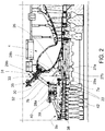
- reference numeral 1 indicates a gas turbine assembly (schematically shown in Figure 1 ).
- the gas turbine assembly 1 comprises a compressor 3, a combustor 4, a gas turbine 5, at least one pressure sensor 7 and a control device (not shown in the attached figures).
- the compressor 3 are the turbine 5 are mounted on the same shaft to form a rotor 8, which extends along an axis A.
- the rotor 8 is coupled to a generator (for simplicity, not shown in the attached figures).
- the rotor 8 comprises a front shaft 10, a plurality of rotor assemblies 11 and a rear shaft 13.
- Each rotor assembly 11 comprises a rotor disk 15 and a plurality of rotor blades 16 coupled to the rotor disk 15 and radially arranged.
- the plurality of rotor disks 15 are arranged in succession between the front shaft 10 and the rear shaft 13 and preferably clamped as a pack by a central tie rod 14. As an alternative, the rotor disks may be welded together.
- a central shaft 17 separates the rotor disks 15 of the compressor 3 from the rotor disks 15 of the turbine 5 and extends through the combustor 4.
- stator assemblies 22 are alternated with the compressor rotor assemblies 11.
- Each stator assembly 22 comprises a stator ring 24 and a plurality of stator vanes 25, which are radially arranged and coupled to the stator ring 24.
- stator vanes 25 in the compressor 3 are coupled to the stator ring 24 and to a compressor stator casing 9a, while stator vanes 25 in the turbine 5 are coupled to the stator ring 24 and to a turbine stator casing 9b.
- Compressor 3 is also provided with an outlet diffuser 26, which is arranged at the outlet of the compressor 3.
- the diffuser 26 is designed to discharge the compressed air into a plenum 30.
- diffuser 26 comprises two shells 27a 27b defining a channel having an increasing section in order to obtain a reduction in velocity of the evolving airflow.
- Shells 27a 27b are coupled to compressor stator casing 9a.
- the shell 27a facing the plenum 30 is provided with a first portion 28a, which is substantially cylindrical, and with a second portion 28b folded on the first portion 28a, which is substantially truncated cone shaped.
- the first portion 28a defines an outer face 29a, while the second portion defines substantially an outer face 29b.
- the plenum 30 is a closed volume delimited at least by an outer casing 31 and by the outlet diffuser 26, wherein compressed air coming from the outlet diffuser 26 is collected.
- the plenum 30 is delimited also by other parts of the gas turbine assembly 1, as the gas turbine casing 9b.
- the plenum 30 At least a part of the combustor 4 is arranged.
- the outer casing 31 is coupled to the compressor stator casing 9a.
- the outer casing 31 has at least one portion 32 which is truncated-cone shaped.
- the portion 32 is provided with a plurality of holes 33 housing the fuel supply conduits 35 of combustor 4.
- the portion 32 has a radius increasing towards the turbine 5.
- the outer casing 31 is fixed to a first portion 38 of the compressor stator casing 9a by means of bolts 39.
- a diaphragm 40 is arranged between a second portion 42 of the compressor stator casing 9a and the outer casing 31.
- the diaphragm 40 is arranged on a plane substantially orthogonal to longitudinal axis A.
- the diaphragm 40 is arranged substantially at the same axial position of the last stator stage 22 of the compressor 3.
- the diaphragm 40 is preferably coupled substantially to the end of the portion 32 having the minimum radius.
- the second portion 42 of the compressor stator casing 9a is configured to support at least the last stator stage 22 of the compressor 3.
- the second portion 42 of the compressor stator casing 9a is configured to support the last seven stator stages 22 of the compressor 3.
- Diffuser 26 is coupled to the second portion 42 of the compressor stator casing 9a.
- the outer casing 31 is also coupled to the turbine stator casing 9b.
- the compressor 3 In use, the compressor 3 is supplied with air. In the compressor 3 the rotation of the compressor rotor assemblies 11, which are alternated with the stator assemblies 22, compress the passing air.
- the compressed air leaving the compressor 3 flows into the plenum 30 through the diffuser 26. Compressed air flows from the plenum 30 into the combustor 4. Inside the combustor 4, the compressed air is mixed with at least one fuel and combusted. The resulting hot gas leaves the combustor 4 and expands in the turbine 5.
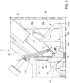
- the gas turbine assembly 1 comprises at least one pressure sensor 7 facing an area of the plenum 30 comprised between the diffuser 26 and the outer casing 31.
- the gas turbine assembly 1 comprises at least one pressure sensor 7 facing an area of the plenum 30 comprised between the diffuser 26 and the portion 32 of the outer casing 31.
- the gas turbine assembly 1 comprises at least one pressure sensor 7a arranged in the plenum 30 between the diffuser 26 and the portion 32 of the outer casing 31 closer to the diffuser 26 than to the outer casing 31.
- the gas turbine assembly 1 comprises at least one pressure sensor 7a arranged between the diffuser 26 and the portion 32 of the outer casing 31 closer to the diffuser 26.
- the pressure sensor 7a faces the area comprised between the outer face 29a and the outer face 29b.
- the pressure sensor 7a is arranged close to the area of coupling between shell 27a and the compressor stator casing 9a.
- the pressure sensor 7a is coupled to the portion of the shell 27a coupled to the compressor stator casing 9a.
- a plurality of pressure sensors 7a is arranged along a circumference extending about the longitudinal axis A.
- pressure sensors 7a are arranged in different sectors of the plenum 30.
- the gas turbine assembly 1 comprises at least one pressure sensor 7b arranged in a pressure tap 43 made in the outer casing 31.
- the pressure tap 43 is defined by a tube 45 housed in a hole 46 of the outer casing 31.
- the hole 46 is made in the portion 32 of the outer casing 31.
- the senor can be arranged between the diffuser 26 and the portion 32 of the outer casing 31 closer to the outer casing 31 than to the diffuser 26.
- a plurality of pressure sensors 7b is arranged along a circumference extending about the longitudinal axis A.
- pressure sensors 7b are arranged in different sectors of the plenum 30.
- the gas turbine assembly comprises only one sensor between sensor 7a and sensor 7b.
- Sensor data detected by sensor 7a and/or sensor 7b are sent to control device 8.
- Figure 3 shows an alternative embodiment according to the present invention, wherein sensor 7b is replaced by a sensor 7c which is arranged at the end 48 of a duct 47 extending from the outer casing 31 into the plenum 30.
- the duct 47 is oriented so as the end 48 is arranged closer to the diffuser 26 than to the outer casing 31.
- the duct 47 is housed in a hole 49 of the outer casing 31.
- the hole 49 is made is the portion 32 of the outer casing 31.
- a plurality of pressure sensors 7c is arranged along a circumference extending about the longitudinal axis A.
- pressure sensors 7c are arranged in different sectors of the plenum 30.
- Sensor data detected by sensor 7a and/or sensor 7c are sent to control device 8.
- the gas turbine assembly comprises only one sensor between sensor 7a and sensor 7c.
- the gas turbine assembly comprises all the sensors 7a, 7b and 7c.
- the overall number of pressure sensors 7a and/or 7b and/or 7c to be installed in the combustor 4 is mainly related to the acoustic modes that have to be monitored.
- the final position of the sensors 7a and/or 7b and/or 7c depends on the acoustic modes to be monitored taking into account also thermo-structural behaviors and/or the necessity to avoid any kind of interference with existing components.
- pressure sensors 7a and/or 7b and/or 7c are pressure probes.
Landscapes
- Engineering & Computer Science (AREA)
- Chemical & Material Sciences (AREA)
- Combustion & Propulsion (AREA)
- Mechanical Engineering (AREA)
- General Engineering & Computer Science (AREA)
- Structures Of Non-Positive Displacement Pumps (AREA)
Priority Applications (2)
| Application Number | Priority Date | Filing Date | Title |
|---|---|---|---|
| EP19425103.9A EP3845740B1 (de) | 2019-12-31 | 2019-12-31 | Gasturbinenanordnung |
| CN202011575751.8A CN113123868B (zh) | 2019-12-31 | 2020-12-28 | 燃气涡轮组件 |
Applications Claiming Priority (1)
| Application Number | Priority Date | Filing Date | Title |
|---|---|---|---|
| EP19425103.9A EP3845740B1 (de) | 2019-12-31 | 2019-12-31 | Gasturbinenanordnung |
Publications (2)
| Publication Number | Publication Date |
|---|---|
| EP3845740A1 true EP3845740A1 (de) | 2021-07-07 |
| EP3845740B1 EP3845740B1 (de) | 2024-04-03 |
Family
ID=69650518
Family Applications (1)
| Application Number | Title | Priority Date | Filing Date |
|---|---|---|---|
| EP19425103.9A Active EP3845740B1 (de) | 2019-12-31 | 2019-12-31 | Gasturbinenanordnung |
Country Status (2)
| Country | Link |
|---|---|
| EP (1) | EP3845740B1 (de) |
| CN (1) | CN113123868B (de) |
Citations (7)
| Publication number | Priority date | Publication date | Assignee | Title |
|---|---|---|---|---|
| JPH07166892A (ja) * | 1993-12-17 | 1995-06-27 | Kobe Steel Ltd | ガスタービンの燃焼器異常診断装置 |
| US20030159446A1 (en) * | 2002-02-15 | 2003-08-28 | Siemens Westinghouse Power Corporation | Gas turbine with flexible combustion sensor connection |
| EP1387062A2 (de) * | 2002-08-02 | 2004-02-04 | General Electric Company | Verfahren/System zum Mapping einer Brennkammer in einer Gasturbine |
| US20090217672A1 (en) * | 2006-01-19 | 2009-09-03 | Siemens Aktiengesellschaft | Fuel Ratio Control in a Combustion Apparatus with Multiple Fuel Supply Lines |
| EP2722508A1 (de) * | 2012-10-22 | 2014-04-23 | Alstom Technology Ltd | Verfahren zum Betreiben einer Gasturbine mit sequentieller Verbrennung und Gasturbine zum Durchführen des Verfahrens |
| US20180230913A1 (en) * | 2017-02-10 | 2018-08-16 | General Electric Company | Pressure Sensor Assembly for a Turbine Engine |
| US20190086085A1 (en) * | 2017-09-21 | 2019-03-21 | General Electric Company | Canted combustor for gas turbine engine |
Family Cites Families (1)
| Publication number | Priority date | Publication date | Assignee | Title |
|---|---|---|---|---|
| US9127554B2 (en) * | 2012-09-04 | 2015-09-08 | Siemens Energy, Inc. | Gas turbine engine with radial diffuser and shortened mid section |
-
2019
- 2019-12-31 EP EP19425103.9A patent/EP3845740B1/de active Active
-
2020
- 2020-12-28 CN CN202011575751.8A patent/CN113123868B/zh active Active
Patent Citations (7)
| Publication number | Priority date | Publication date | Assignee | Title |
|---|---|---|---|---|
| JPH07166892A (ja) * | 1993-12-17 | 1995-06-27 | Kobe Steel Ltd | ガスタービンの燃焼器異常診断装置 |
| US20030159446A1 (en) * | 2002-02-15 | 2003-08-28 | Siemens Westinghouse Power Corporation | Gas turbine with flexible combustion sensor connection |
| EP1387062A2 (de) * | 2002-08-02 | 2004-02-04 | General Electric Company | Verfahren/System zum Mapping einer Brennkammer in einer Gasturbine |
| US20090217672A1 (en) * | 2006-01-19 | 2009-09-03 | Siemens Aktiengesellschaft | Fuel Ratio Control in a Combustion Apparatus with Multiple Fuel Supply Lines |
| EP2722508A1 (de) * | 2012-10-22 | 2014-04-23 | Alstom Technology Ltd | Verfahren zum Betreiben einer Gasturbine mit sequentieller Verbrennung und Gasturbine zum Durchführen des Verfahrens |
| US20180230913A1 (en) * | 2017-02-10 | 2018-08-16 | General Electric Company | Pressure Sensor Assembly for a Turbine Engine |
| US20190086085A1 (en) * | 2017-09-21 | 2019-03-21 | General Electric Company | Canted combustor for gas turbine engine |
Also Published As
| Publication number | Publication date |
|---|---|
| EP3845740B1 (de) | 2024-04-03 |
| CN113123868A (zh) | 2021-07-16 |
| CN113123868B (zh) | 2025-11-21 |
Similar Documents
| Publication | Publication Date | Title |
|---|---|---|
| CN101153546B (zh) | 双轴燃气涡轮 | |
| CN102119268A (zh) | 燃气轮机中使用的具有带排气口的线性流动路径的过渡件 | |
| US20140318148A1 (en) | Burner seal for gas-turbine combustion chamber head and heat shield | |
| US10844750B2 (en) | Method of disassembling and assembling gas turbine and gas turbine assembled thereby | |
| US20150292357A1 (en) | Aircraft gas turbine having a core engine casing with cooling-air tubes | |
| US20110016884A1 (en) | Cooling passage cover, manufacturing method of the cover, and gas turbine | |
| US20150152743A1 (en) | Method for minimizing the gap between a rotor and a housing | |
| KR102426622B1 (ko) | 연소기 및 이를 포함하는 가스터빈 | |
| EP2249003B1 (de) | Gasturbine | |
| US8734089B2 (en) | Damper seal and vane assembly for a gas turbine engine | |
| EP2261567B1 (de) | Gasturbine und verfahren zum ausbilden eines einführlochs für eine gasturbinenbrennkammer | |
| US11060405B2 (en) | Turbine engine with a swirler | |
| EP3845740B1 (de) | Gasturbinenanordnung | |
| US20190003381A1 (en) | Method of assembling and disassembling gas turbine and gas turbine assembled thereby | |
| EP3296573A1 (de) | Methodik zur behandlung von umlaufendem strömungsabriss in einem gasturbinen-verdichter | |
| KR102103580B1 (ko) | 터빈 블레이드 균열 검출 시스템 | |
| CN108266231B (zh) | 用于燃气涡轮的最后一个涡轮转子盘、转子以及燃气涡轮 | |
| EP3974723B1 (de) | Gasturbine für kraftwerk mit einer dämpfungsvorrichtung | |
| KR102433705B1 (ko) | 스테이터 및 이를 포함하는 터보머신 | |
| US11761347B2 (en) | Exhaust frame differential cooling system | |
| US20190085727A1 (en) | Turbine stator, turbine, and gas turbine including the same | |
| US9297271B2 (en) | Turbine blade monitoring arrangement and method of manufacturing | |
| KR102080569B1 (ko) | 가스터빈의 분해 및 조립방법과 이에 의해 조립된 가스터빈 | |
| EP4206441A1 (de) | Statoranordnung für einen verdichter einer gasturbinenanordnung und verdichter | |
| US10590797B2 (en) | Impedance tube having a machined union |
Legal Events
| Date | Code | Title | Description |
|---|---|---|---|
| PUAI | Public reference made under article 153(3) epc to a published international application that has entered the european phase |
Free format text: ORIGINAL CODE: 0009012 |
|
| STAA | Information on the status of an ep patent application or granted ep patent |
Free format text: STATUS: THE APPLICATION HAS BEEN PUBLISHED |
|
| AK | Designated contracting states |
Kind code of ref document: A1 Designated state(s): AL AT BE BG CH CY CZ DE DK EE ES FI FR GB GR HR HU IE IS IT LI LT LU LV MC MK MT NL NO PL PT RO RS SE SI SK SM TR |
|
| STAA | Information on the status of an ep patent application or granted ep patent |
Free format text: STATUS: REQUEST FOR EXAMINATION WAS MADE |
|
| 17P | Request for examination filed |
Effective date: 20220107 |
|
| RBV | Designated contracting states (corrected) |
Designated state(s): AL AT BE BG CH CY CZ DE DK EE ES FI FR GB GR HR HU IE IS IT LI LT LU LV MC MK MT NL NO PL PT RO RS SE SI SK SM TR |
|
| GRAP | Despatch of communication of intention to grant a patent |
Free format text: ORIGINAL CODE: EPIDOSNIGR1 |
|
| STAA | Information on the status of an ep patent application or granted ep patent |
Free format text: STATUS: GRANT OF PATENT IS INTENDED |
|
| INTG | Intention to grant announced |
Effective date: 20230823 |
|
| GRAS | Grant fee paid |
Free format text: ORIGINAL CODE: EPIDOSNIGR3 |
|
| GRAA | (expected) grant |
Free format text: ORIGINAL CODE: 0009210 |
|
| STAA | Information on the status of an ep patent application or granted ep patent |
Free format text: STATUS: THE PATENT HAS BEEN GRANTED |
|
| AK | Designated contracting states |
Kind code of ref document: B1 Designated state(s): AL AT BE BG CH CY CZ DE DK EE ES FI FR GB GR HR HU IE IS IT LI LT LU LV MC MK MT NL NO PL PT RO RS SE SI SK SM TR |
|
| REG | Reference to a national code |
Ref country code: CH Ref legal event code: EP |
|
| REG | Reference to a national code |
Ref country code: IE Ref legal event code: FG4D |
|
| REG | Reference to a national code |
Ref country code: DE Ref legal event code: R096 Ref document number: 602019049393 Country of ref document: DE |
|
| P01 | Opt-out of the competence of the unified patent court (upc) registered |
Effective date: 20240430 |
|
| REG | Reference to a national code |
Ref country code: LT Ref legal event code: MG9D |
|
| REG | Reference to a national code |
Ref country code: NL Ref legal event code: MP Effective date: 20240403 |
|
| REG | Reference to a national code |
Ref country code: AT Ref legal event code: MK05 Ref document number: 1672522 Country of ref document: AT Kind code of ref document: T Effective date: 20240403 |
|
| PG25 | Lapsed in a contracting state [announced via postgrant information from national office to epo] |
Ref country code: NL Free format text: LAPSE BECAUSE OF FAILURE TO SUBMIT A TRANSLATION OF THE DESCRIPTION OR TO PAY THE FEE WITHIN THE PRESCRIBED TIME-LIMIT Effective date: 20240403 |
|
| PG25 | Lapsed in a contracting state [announced via postgrant information from national office to epo] |
Ref country code: NL Free format text: LAPSE BECAUSE OF FAILURE TO SUBMIT A TRANSLATION OF THE DESCRIPTION OR TO PAY THE FEE WITHIN THE PRESCRIBED TIME-LIMIT Effective date: 20240403 |
|
| PG25 | Lapsed in a contracting state [announced via postgrant information from national office to epo] |
Ref country code: IS Free format text: LAPSE BECAUSE OF FAILURE TO SUBMIT A TRANSLATION OF THE DESCRIPTION OR TO PAY THE FEE WITHIN THE PRESCRIBED TIME-LIMIT Effective date: 20240803 |
|
| PG25 | Lapsed in a contracting state [announced via postgrant information from national office to epo] |
Ref country code: BG Free format text: LAPSE BECAUSE OF FAILURE TO SUBMIT A TRANSLATION OF THE DESCRIPTION OR TO PAY THE FEE WITHIN THE PRESCRIBED TIME-LIMIT Effective date: 20240403 |
|
| PG25 | Lapsed in a contracting state [announced via postgrant information from national office to epo] |
Ref country code: HR Free format text: LAPSE BECAUSE OF FAILURE TO SUBMIT A TRANSLATION OF THE DESCRIPTION OR TO PAY THE FEE WITHIN THE PRESCRIBED TIME-LIMIT Effective date: 20240403 Ref country code: FI Free format text: LAPSE BECAUSE OF FAILURE TO SUBMIT A TRANSLATION OF THE DESCRIPTION OR TO PAY THE FEE WITHIN THE PRESCRIBED TIME-LIMIT Effective date: 20240403 |
|
| PG25 | Lapsed in a contracting state [announced via postgrant information from national office to epo] |
Ref country code: GR Free format text: LAPSE BECAUSE OF FAILURE TO SUBMIT A TRANSLATION OF THE DESCRIPTION OR TO PAY THE FEE WITHIN THE PRESCRIBED TIME-LIMIT Effective date: 20240704 |
|
| PG25 | Lapsed in a contracting state [announced via postgrant information from national office to epo] |
Ref country code: PT Free format text: LAPSE BECAUSE OF FAILURE TO SUBMIT A TRANSLATION OF THE DESCRIPTION OR TO PAY THE FEE WITHIN THE PRESCRIBED TIME-LIMIT Effective date: 20240805 |
|
| PG25 | Lapsed in a contracting state [announced via postgrant information from national office to epo] |
Ref country code: ES Free format text: LAPSE BECAUSE OF FAILURE TO SUBMIT A TRANSLATION OF THE DESCRIPTION OR TO PAY THE FEE WITHIN THE PRESCRIBED TIME-LIMIT Effective date: 20240403 |
|
| PG25 | Lapsed in a contracting state [announced via postgrant information from national office to epo] |
Ref country code: CZ Free format text: LAPSE BECAUSE OF FAILURE TO SUBMIT A TRANSLATION OF THE DESCRIPTION OR TO PAY THE FEE WITHIN THE PRESCRIBED TIME-LIMIT Effective date: 20240403 |
|
| PG25 | Lapsed in a contracting state [announced via postgrant information from national office to epo] |
Ref country code: AT Free format text: LAPSE BECAUSE OF FAILURE TO SUBMIT A TRANSLATION OF THE DESCRIPTION OR TO PAY THE FEE WITHIN THE PRESCRIBED TIME-LIMIT Effective date: 20240403 |
|
| PG25 | Lapsed in a contracting state [announced via postgrant information from national office to epo] |
Ref country code: PL Free format text: LAPSE BECAUSE OF FAILURE TO SUBMIT A TRANSLATION OF THE DESCRIPTION OR TO PAY THE FEE WITHIN THE PRESCRIBED TIME-LIMIT Effective date: 20240403 |
|
| PG25 | Lapsed in a contracting state [announced via postgrant information from national office to epo] |
Ref country code: LV Free format text: LAPSE BECAUSE OF FAILURE TO SUBMIT A TRANSLATION OF THE DESCRIPTION OR TO PAY THE FEE WITHIN THE PRESCRIBED TIME-LIMIT Effective date: 20240403 |
|
| PG25 | Lapsed in a contracting state [announced via postgrant information from national office to epo] |
Ref country code: PT Free format text: LAPSE BECAUSE OF FAILURE TO SUBMIT A TRANSLATION OF THE DESCRIPTION OR TO PAY THE FEE WITHIN THE PRESCRIBED TIME-LIMIT Effective date: 20240805 Ref country code: PL Free format text: LAPSE BECAUSE OF FAILURE TO SUBMIT A TRANSLATION OF THE DESCRIPTION OR TO PAY THE FEE WITHIN THE PRESCRIBED TIME-LIMIT Effective date: 20240403 Ref country code: NO Free format text: LAPSE BECAUSE OF FAILURE TO SUBMIT A TRANSLATION OF THE DESCRIPTION OR TO PAY THE FEE WITHIN THE PRESCRIBED TIME-LIMIT Effective date: 20240703 Ref country code: LV Free format text: LAPSE BECAUSE OF FAILURE TO SUBMIT A TRANSLATION OF THE DESCRIPTION OR TO PAY THE FEE WITHIN THE PRESCRIBED TIME-LIMIT Effective date: 20240403 Ref country code: IS Free format text: LAPSE BECAUSE OF FAILURE TO SUBMIT A TRANSLATION OF THE DESCRIPTION OR TO PAY THE FEE WITHIN THE PRESCRIBED TIME-LIMIT Effective date: 20240803 Ref country code: HR Free format text: LAPSE BECAUSE OF FAILURE TO SUBMIT A TRANSLATION OF THE DESCRIPTION OR TO PAY THE FEE WITHIN THE PRESCRIBED TIME-LIMIT Effective date: 20240403 Ref country code: GR Free format text: LAPSE BECAUSE OF FAILURE TO SUBMIT A TRANSLATION OF THE DESCRIPTION OR TO PAY THE FEE WITHIN THE PRESCRIBED TIME-LIMIT Effective date: 20240704 Ref country code: FI Free format text: LAPSE BECAUSE OF FAILURE TO SUBMIT A TRANSLATION OF THE DESCRIPTION OR TO PAY THE FEE WITHIN THE PRESCRIBED TIME-LIMIT Effective date: 20240403 Ref country code: ES Free format text: LAPSE BECAUSE OF FAILURE TO SUBMIT A TRANSLATION OF THE DESCRIPTION OR TO PAY THE FEE WITHIN THE PRESCRIBED TIME-LIMIT Effective date: 20240403 Ref country code: CZ Free format text: LAPSE BECAUSE OF FAILURE TO SUBMIT A TRANSLATION OF THE DESCRIPTION OR TO PAY THE FEE WITHIN THE PRESCRIBED TIME-LIMIT Effective date: 20240403 Ref country code: BG Free format text: LAPSE BECAUSE OF FAILURE TO SUBMIT A TRANSLATION OF THE DESCRIPTION OR TO PAY THE FEE WITHIN THE PRESCRIBED TIME-LIMIT Effective date: 20240403 Ref country code: AT Free format text: LAPSE BECAUSE OF FAILURE TO SUBMIT A TRANSLATION OF THE DESCRIPTION OR TO PAY THE FEE WITHIN THE PRESCRIBED TIME-LIMIT Effective date: 20240403 Ref country code: RS Free format text: LAPSE BECAUSE OF FAILURE TO SUBMIT A TRANSLATION OF THE DESCRIPTION OR TO PAY THE FEE WITHIN THE PRESCRIBED TIME-LIMIT Effective date: 20240703 |
|
| REG | Reference to a national code |
Ref country code: DE Ref legal event code: R097 Ref document number: 602019049393 Country of ref document: DE |
|
| PGFP | Annual fee paid to national office [announced via postgrant information from national office to epo] |
Ref country code: DE Payment date: 20241216 Year of fee payment: 6 |
|
| PG25 | Lapsed in a contracting state [announced via postgrant information from national office to epo] |
Ref country code: DK Free format text: LAPSE BECAUSE OF FAILURE TO SUBMIT A TRANSLATION OF THE DESCRIPTION OR TO PAY THE FEE WITHIN THE PRESCRIBED TIME-LIMIT Effective date: 20240403 |
|
| PG25 | Lapsed in a contracting state [announced via postgrant information from national office to epo] |
Ref country code: EE Free format text: LAPSE BECAUSE OF FAILURE TO SUBMIT A TRANSLATION OF THE DESCRIPTION OR TO PAY THE FEE WITHIN THE PRESCRIBED TIME-LIMIT Effective date: 20240403 |
|
| PG25 | Lapsed in a contracting state [announced via postgrant information from national office to epo] |
Ref country code: RO Free format text: LAPSE BECAUSE OF FAILURE TO SUBMIT A TRANSLATION OF THE DESCRIPTION OR TO PAY THE FEE WITHIN THE PRESCRIBED TIME-LIMIT Effective date: 20240403 Ref country code: SK Free format text: LAPSE BECAUSE OF FAILURE TO SUBMIT A TRANSLATION OF THE DESCRIPTION OR TO PAY THE FEE WITHIN THE PRESCRIBED TIME-LIMIT Effective date: 20240403 |
|
| PG25 | Lapsed in a contracting state [announced via postgrant information from national office to epo] |
Ref country code: SM Free format text: LAPSE BECAUSE OF FAILURE TO SUBMIT A TRANSLATION OF THE DESCRIPTION OR TO PAY THE FEE WITHIN THE PRESCRIBED TIME-LIMIT Effective date: 20240403 |
|
| PG25 | Lapsed in a contracting state [announced via postgrant information from national office to epo] |
Ref country code: SM Free format text: LAPSE BECAUSE OF FAILURE TO SUBMIT A TRANSLATION OF THE DESCRIPTION OR TO PAY THE FEE WITHIN THE PRESCRIBED TIME-LIMIT Effective date: 20240403 Ref country code: SK Free format text: LAPSE BECAUSE OF FAILURE TO SUBMIT A TRANSLATION OF THE DESCRIPTION OR TO PAY THE FEE WITHIN THE PRESCRIBED TIME-LIMIT Effective date: 20240403 Ref country code: RO Free format text: LAPSE BECAUSE OF FAILURE TO SUBMIT A TRANSLATION OF THE DESCRIPTION OR TO PAY THE FEE WITHIN THE PRESCRIBED TIME-LIMIT Effective date: 20240403 Ref country code: EE Free format text: LAPSE BECAUSE OF FAILURE TO SUBMIT A TRANSLATION OF THE DESCRIPTION OR TO PAY THE FEE WITHIN THE PRESCRIBED TIME-LIMIT Effective date: 20240403 Ref country code: DK Free format text: LAPSE BECAUSE OF FAILURE TO SUBMIT A TRANSLATION OF THE DESCRIPTION OR TO PAY THE FEE WITHIN THE PRESCRIBED TIME-LIMIT Effective date: 20240403 |
|
| PLBE | No opposition filed within time limit |
Free format text: ORIGINAL CODE: 0009261 |
|
| STAA | Information on the status of an ep patent application or granted ep patent |
Free format text: STATUS: NO OPPOSITION FILED WITHIN TIME LIMIT |
|
| 26N | No opposition filed |
Effective date: 20250106 |
|
| PG25 | Lapsed in a contracting state [announced via postgrant information from national office to epo] |
Ref country code: SI Free format text: LAPSE BECAUSE OF FAILURE TO SUBMIT A TRANSLATION OF THE DESCRIPTION OR TO PAY THE FEE WITHIN THE PRESCRIBED TIME-LIMIT Effective date: 20240403 |
|
| PG25 | Lapsed in a contracting state [announced via postgrant information from national office to epo] |
Ref country code: MC Free format text: LAPSE BECAUSE OF FAILURE TO SUBMIT A TRANSLATION OF THE DESCRIPTION OR TO PAY THE FEE WITHIN THE PRESCRIBED TIME-LIMIT Effective date: 20240403 |
|
| REG | Reference to a national code |
Ref country code: CH Ref legal event code: PL |
|
| PG25 | Lapsed in a contracting state [announced via postgrant information from national office to epo] |
Ref country code: LU Free format text: LAPSE BECAUSE OF NON-PAYMENT OF DUE FEES Effective date: 20241231 |
|
| GBPC | Gb: european patent ceased through non-payment of renewal fee |
Effective date: 20241231 |
|
| PG25 | Lapsed in a contracting state [announced via postgrant information from national office to epo] |
Ref country code: SE Free format text: LAPSE BECAUSE OF FAILURE TO SUBMIT A TRANSLATION OF THE DESCRIPTION OR TO PAY THE FEE WITHIN THE PRESCRIBED TIME-LIMIT Effective date: 20240403 |
|
| REG | Reference to a national code |
Ref country code: BE Ref legal event code: MM Effective date: 20241231 |
|
| PG25 | Lapsed in a contracting state [announced via postgrant information from national office to epo] |
Ref country code: GB Free format text: LAPSE BECAUSE OF NON-PAYMENT OF DUE FEES Effective date: 20241231 Ref country code: BE Free format text: LAPSE BECAUSE OF NON-PAYMENT OF DUE FEES Effective date: 20241231 |
|
| PG25 | Lapsed in a contracting state [announced via postgrant information from national office to epo] |
Ref country code: FR Free format text: LAPSE BECAUSE OF NON-PAYMENT OF DUE FEES Effective date: 20241231 |
|
| PG25 | Lapsed in a contracting state [announced via postgrant information from national office to epo] |
Ref country code: CH Free format text: LAPSE BECAUSE OF NON-PAYMENT OF DUE FEES Effective date: 20241231 |
|
| PG25 | Lapsed in a contracting state [announced via postgrant information from national office to epo] |
Ref country code: IE Free format text: LAPSE BECAUSE OF NON-PAYMENT OF DUE FEES Effective date: 20241231 |
|
| PG25 | Lapsed in a contracting state [announced via postgrant information from national office to epo] |
Ref country code: IT Free format text: LAPSE BECAUSE OF NON-PAYMENT OF DUE FEES Effective date: 20241231 |