EP3845740A1 - Gas turbine assembly - Google Patents
Gas turbine assembly Download PDFInfo
- Publication number
- EP3845740A1 EP3845740A1 EP19425103.9A EP19425103A EP3845740A1 EP 3845740 A1 EP3845740 A1 EP 3845740A1 EP 19425103 A EP19425103 A EP 19425103A EP 3845740 A1 EP3845740 A1 EP 3845740A1
- Authority
- EP
- European Patent Office
- Prior art keywords
- gas turbine
- turbine assembly
- outer casing
- assembly according
- plenum
- Prior art date
- Legal status (The legal status is an assumption and is not a legal conclusion. Google has not performed a legal analysis and makes no representation as to the accuracy of the status listed.)
- Granted
Links
Images

Classifications
-
- F—MECHANICAL ENGINEERING; LIGHTING; HEATING; WEAPONS; BLASTING
- F01—MACHINES OR ENGINES IN GENERAL; ENGINE PLANTS IN GENERAL; STEAM ENGINES
- F01D—NON-POSITIVE DISPLACEMENT MACHINES OR ENGINES, e.g. STEAM TURBINES
- F01D17/00—Regulating or controlling by varying flow
- F01D17/02—Arrangement of sensing elements
- F01D17/08—Arrangement of sensing elements responsive to condition of working-fluid, e.g. pressure
-
- F—MECHANICAL ENGINEERING; LIGHTING; HEATING; WEAPONS; BLASTING
- F02—COMBUSTION ENGINES; HOT-GAS OR COMBUSTION-PRODUCT ENGINE PLANTS
- F02C—GAS-TURBINE PLANTS; AIR INTAKES FOR JET-PROPULSION PLANTS; CONTROLLING FUEL SUPPLY IN AIR-BREATHING JET-PROPULSION PLANTS
- F02C3/00—Gas-turbine plants characterised by the use of combustion products as the working fluid
- F02C3/04—Gas-turbine plants characterised by the use of combustion products as the working fluid having a turbine driving a compressor
-
- F—MECHANICAL ENGINEERING; LIGHTING; HEATING; WEAPONS; BLASTING
- F02—COMBUSTION ENGINES; HOT-GAS OR COMBUSTION-PRODUCT ENGINE PLANTS
- F02C—GAS-TURBINE PLANTS; AIR INTAKES FOR JET-PROPULSION PLANTS; CONTROLLING FUEL SUPPLY IN AIR-BREATHING JET-PROPULSION PLANTS
- F02C7/00—Features, components parts, details or accessories, not provided for in, or of interest apart form groups F02C1/00 - F02C6/00; Air intakes for jet-propulsion plants
-
- F—MECHANICAL ENGINEERING; LIGHTING; HEATING; WEAPONS; BLASTING
- F05—INDEXING SCHEMES RELATING TO ENGINES OR PUMPS IN VARIOUS SUBCLASSES OF CLASSES F01-F04
- F05D—INDEXING SCHEME FOR ASPECTS RELATING TO NON-POSITIVE-DISPLACEMENT MACHINES OR ENGINES, GAS-TURBINES OR JET-PROPULSION PLANTS
- F05D2260/00—Function
- F05D2260/96—Preventing, counteracting or reducing vibration or noise
- F05D2260/964—Preventing, counteracting or reducing vibration or noise counteracting thermoacoustic noise
-
- F—MECHANICAL ENGINEERING; LIGHTING; HEATING; WEAPONS; BLASTING
- F05—INDEXING SCHEMES RELATING TO ENGINES OR PUMPS IN VARIOUS SUBCLASSES OF CLASSES F01-F04
- F05D—INDEXING SCHEME FOR ASPECTS RELATING TO NON-POSITIVE-DISPLACEMENT MACHINES OR ENGINES, GAS-TURBINES OR JET-PROPULSION PLANTS
- F05D2270/00—Control
- F05D2270/01—Purpose of the control system
- F05D2270/14—Purpose of the control system to control thermoacoustic behaviour in the combustion chambers
-
- F—MECHANICAL ENGINEERING; LIGHTING; HEATING; WEAPONS; BLASTING
- F05—INDEXING SCHEMES RELATING TO ENGINES OR PUMPS IN VARIOUS SUBCLASSES OF CLASSES F01-F04
- F05D—INDEXING SCHEME FOR ASPECTS RELATING TO NON-POSITIVE-DISPLACEMENT MACHINES OR ENGINES, GAS-TURBINES OR JET-PROPULSION PLANTS
- F05D2270/00—Control
- F05D2270/30—Control parameters, e.g. input parameters
- F05D2270/333—Noise or sound levels
Definitions
- the present invention relates to a gas turbine assembly.
- gas turbine assembly of the present invention is part of a plant for the production of electrical energy.
- a gas turbine assembly for power plants comprises a compressor, a combustor and a turbine.
- the compressor comprises an inlet supplied with air and a plurality of rotating blades compressing the passing air.
- the compressed air leaving the compressor flows into a plenum, i.e. a closed volume delimited by an outer casing, and from there into the combustor.
- a plenum i.e. a closed volume delimited by an outer casing
- the compressed air is mixed with at least one fuel and combusted.
- the resulting hot gas leaves the combustor and expands in the turbine. In the turbine the hot gas expansion moves rotating blades connected to a rotor, performing work.
- acoustic oscillations may be triggered spontaneously (here and hereinafter identified with the term 'humming' typically used in the sector of reference), which are destructive to the structural integrity of the combustor.
- the monitoring of the acoustic pressure oscillations should be performed in reliable manner as the risks connected to a not optimal monitoring are really serious: reduction of the power output and loss of the integrity of components of the combustor.
- a gas turbine assembly comprising:
- the present invention can be applied on existing gas turbine assemblies.
- reference numeral 1 indicates a gas turbine assembly (schematically shown in Figure 1 ).
- the gas turbine assembly 1 comprises a compressor 3, a combustor 4, a gas turbine 5, at least one pressure sensor 7 and a control device (not shown in the attached figures).
- the compressor 3 are the turbine 5 are mounted on the same shaft to form a rotor 8, which extends along an axis A.
- the rotor 8 is coupled to a generator (for simplicity, not shown in the attached figures).
- the rotor 8 comprises a front shaft 10, a plurality of rotor assemblies 11 and a rear shaft 13.
- Each rotor assembly 11 comprises a rotor disk 15 and a plurality of rotor blades 16 coupled to the rotor disk 15 and radially arranged.
- the plurality of rotor disks 15 are arranged in succession between the front shaft 10 and the rear shaft 13 and preferably clamped as a pack by a central tie rod 14. As an alternative, the rotor disks may be welded together.
- a central shaft 17 separates the rotor disks 15 of the compressor 3 from the rotor disks 15 of the turbine 5 and extends through the combustor 4.
- stator assemblies 22 are alternated with the compressor rotor assemblies 11.
- Each stator assembly 22 comprises a stator ring 24 and a plurality of stator vanes 25, which are radially arranged and coupled to the stator ring 24.
- stator vanes 25 in the compressor 3 are coupled to the stator ring 24 and to a compressor stator casing 9a, while stator vanes 25 in the turbine 5 are coupled to the stator ring 24 and to a turbine stator casing 9b.
- Compressor 3 is also provided with an outlet diffuser 26, which is arranged at the outlet of the compressor 3.
- the diffuser 26 is designed to discharge the compressed air into a plenum 30.
- diffuser 26 comprises two shells 27a 27b defining a channel having an increasing section in order to obtain a reduction in velocity of the evolving airflow.
- Shells 27a 27b are coupled to compressor stator casing 9a.
- the shell 27a facing the plenum 30 is provided with a first portion 28a, which is substantially cylindrical, and with a second portion 28b folded on the first portion 28a, which is substantially truncated cone shaped.
- the first portion 28a defines an outer face 29a, while the second portion defines substantially an outer face 29b.
- the plenum 30 is a closed volume delimited at least by an outer casing 31 and by the outlet diffuser 26, wherein compressed air coming from the outlet diffuser 26 is collected.
- the plenum 30 is delimited also by other parts of the gas turbine assembly 1, as the gas turbine casing 9b.
- the plenum 30 At least a part of the combustor 4 is arranged.
- the outer casing 31 is coupled to the compressor stator casing 9a.
- the outer casing 31 has at least one portion 32 which is truncated-cone shaped.
- the portion 32 is provided with a plurality of holes 33 housing the fuel supply conduits 35 of combustor 4.
- the portion 32 has a radius increasing towards the turbine 5.
- the outer casing 31 is fixed to a first portion 38 of the compressor stator casing 9a by means of bolts 39.
- a diaphragm 40 is arranged between a second portion 42 of the compressor stator casing 9a and the outer casing 31.
- the diaphragm 40 is arranged on a plane substantially orthogonal to longitudinal axis A.
- the diaphragm 40 is arranged substantially at the same axial position of the last stator stage 22 of the compressor 3.
- the diaphragm 40 is preferably coupled substantially to the end of the portion 32 having the minimum radius.
- the second portion 42 of the compressor stator casing 9a is configured to support at least the last stator stage 22 of the compressor 3.
- the second portion 42 of the compressor stator casing 9a is configured to support the last seven stator stages 22 of the compressor 3.
- Diffuser 26 is coupled to the second portion 42 of the compressor stator casing 9a.
- the outer casing 31 is also coupled to the turbine stator casing 9b.
- the compressor 3 In use, the compressor 3 is supplied with air. In the compressor 3 the rotation of the compressor rotor assemblies 11, which are alternated with the stator assemblies 22, compress the passing air.
- the compressed air leaving the compressor 3 flows into the plenum 30 through the diffuser 26. Compressed air flows from the plenum 30 into the combustor 4. Inside the combustor 4, the compressed air is mixed with at least one fuel and combusted. The resulting hot gas leaves the combustor 4 and expands in the turbine 5.
- the gas turbine assembly 1 comprises at least one pressure sensor 7 facing an area of the plenum 30 comprised between the diffuser 26 and the outer casing 31.
- the gas turbine assembly 1 comprises at least one pressure sensor 7 facing an area of the plenum 30 comprised between the diffuser 26 and the portion 32 of the outer casing 31.
- the gas turbine assembly 1 comprises at least one pressure sensor 7a arranged in the plenum 30 between the diffuser 26 and the portion 32 of the outer casing 31 closer to the diffuser 26 than to the outer casing 31.
- the gas turbine assembly 1 comprises at least one pressure sensor 7a arranged between the diffuser 26 and the portion 32 of the outer casing 31 closer to the diffuser 26.
- the pressure sensor 7a faces the area comprised between the outer face 29a and the outer face 29b.
- the pressure sensor 7a is arranged close to the area of coupling between shell 27a and the compressor stator casing 9a.
- the pressure sensor 7a is coupled to the portion of the shell 27a coupled to the compressor stator casing 9a.
- a plurality of pressure sensors 7a is arranged along a circumference extending about the longitudinal axis A.
- pressure sensors 7a are arranged in different sectors of the plenum 30.
- the gas turbine assembly 1 comprises at least one pressure sensor 7b arranged in a pressure tap 43 made in the outer casing 31.
- the pressure tap 43 is defined by a tube 45 housed in a hole 46 of the outer casing 31.
- the hole 46 is made in the portion 32 of the outer casing 31.
- the senor can be arranged between the diffuser 26 and the portion 32 of the outer casing 31 closer to the outer casing 31 than to the diffuser 26.
- a plurality of pressure sensors 7b is arranged along a circumference extending about the longitudinal axis A.
- pressure sensors 7b are arranged in different sectors of the plenum 30.
- the gas turbine assembly comprises only one sensor between sensor 7a and sensor 7b.
- Sensor data detected by sensor 7a and/or sensor 7b are sent to control device 8.
- Figure 3 shows an alternative embodiment according to the present invention, wherein sensor 7b is replaced by a sensor 7c which is arranged at the end 48 of a duct 47 extending from the outer casing 31 into the plenum 30.
- the duct 47 is oriented so as the end 48 is arranged closer to the diffuser 26 than to the outer casing 31.
- the duct 47 is housed in a hole 49 of the outer casing 31.
- the hole 49 is made is the portion 32 of the outer casing 31.
- a plurality of pressure sensors 7c is arranged along a circumference extending about the longitudinal axis A.
- pressure sensors 7c are arranged in different sectors of the plenum 30.
- Sensor data detected by sensor 7a and/or sensor 7c are sent to control device 8.
- the gas turbine assembly comprises only one sensor between sensor 7a and sensor 7c.
- the gas turbine assembly comprises all the sensors 7a, 7b and 7c.
- the overall number of pressure sensors 7a and/or 7b and/or 7c to be installed in the combustor 4 is mainly related to the acoustic modes that have to be monitored.
- the final position of the sensors 7a and/or 7b and/or 7c depends on the acoustic modes to be monitored taking into account also thermo-structural behaviors and/or the necessity to avoid any kind of interference with existing components.
- pressure sensors 7a and/or 7b and/or 7c are pressure probes.
Landscapes
- Engineering & Computer Science (AREA)
- Chemical & Material Sciences (AREA)
- Combustion & Propulsion (AREA)
- Mechanical Engineering (AREA)
- General Engineering & Computer Science (AREA)
- Structures Of Non-Positive Displacement Pumps (AREA)
Abstract
Description
- The present invention relates to a gas turbine assembly.
- In particular, the gas turbine assembly of the present invention is part of a plant for the production of electrical energy.
- As is known, a gas turbine assembly for power plants comprises a compressor, a combustor and a turbine.
- In particular, the compressor comprises an inlet supplied with air and a plurality of rotating blades compressing the passing air. The compressed air leaving the compressor flows into a plenum, i.e. a closed volume delimited by an outer casing, and from there into the combustor. Inside the combustor, the compressed air is mixed with at least one fuel and combusted. The resulting hot gas leaves the combustor and expands in the turbine. In the turbine the hot gas expansion moves rotating blades connected to a rotor, performing work.
- In recent years, under the pressure of increasingly stringent regulations in terms of emissions of polluting substances, combustion techniques have been oriented towards the use of the so-called "lean premix" technology, which provides for the use of combustors in which the fuel is premixed with air before being burned.
- In combustors of this type, in which lean fuel mixtures are burned, at high powers, acoustic oscillations may be triggered spontaneously (here and hereinafter identified with the term 'humming' typically used in the sector of reference), which are destructive to the structural integrity of the combustor.
- Therefore monitoring the acoustic pressure oscillations in the combustor is fundamental for a reliable and efficient operation of the gas turbine assembly.
- However, the monitoring of the acoustic pressure oscillations should be performed in reliable manner as the risks connected to a not optimal monitoring are really serious: reduction of the power output and loss of the integrity of components of the combustor.
- However, the current solutions are not able to detect pressure fluctuations in a reliable way. In particular, known solutions do not show a full sensibility to the dynamic phenomena of interest for the correct engine operations, especially for some frequency bandwidths of interest.
- It is therefore an object of the present invention to provide a gas turbine assembly, which enables avoiding or at least mitigating the described drawbacks.
- In particular, it is an object of the present invention to provide a gas turbine assembly configured to allow a reliable detection of pressure fluctuations.
- According to the present invention, there is provided a gas turbine assembly comprising:
- a compressor configured to compress air; the compressor extending along a longitudinal axis and being provided with an outlet diffuser and with a compressor casing;
- a plenum, which is a closed volume delimited at least by an outer casing coupled to the compressor casing and by the outlet diffuser; the outlet diffuser being designed to discharge the compressed air into the plenum;
- a combustor partially arranged in the plenum;
- at least one pressure sensor facing an area of the plenum comprised between the outer casing and the outlet diffuser.
- Thanks to the arrangement of the pressure sensor according to the present invention, an enhanced monitoring of the pressure amplitudes is achieved, with appreciable improvements in the engine tuning and operation and without affecting the overall engine efficiency in terms of air consumption or variations in the operating conditions. In particular, thanks to the location of the pressure sensor according to the present invention a better sensitivity to all the frequency bandwidths of interest is achieved.
- Advantageously, the present invention can be applied on existing gas turbine assemblies.
- The present invention will now be described with reference to the accompanying drawings, which illustrate some non-limiting embodiments, in which:
-
Figure 1 is a schematic section view, with parts removed, of a gas turbine assembly according to the present invention; -
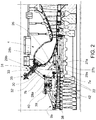
Figure 2 is an enlarged view of a detail of the a gas turbine assembly offigure 1 ; -
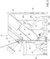
Figure 3 is a schematic section view, with parts removed, of a further detail of the gas turbine assembly offigure 1 ; -
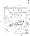
Figure 4 is a schematic section view, with parts removed, of the further detail of the gas turbine assembly offigure 2 according to an alternative embodiment. - In
figure 1 reference numeral 1 indicates a gas turbine assembly (schematically shown inFigure 1 ). - -The gas turbine assembly 1 comprises a
compressor 3, acombustor 4, agas turbine 5, at least one pressure sensor 7 and a control device (not shown in the attached figures). - The
compressor 3 are theturbine 5 are mounted on the same shaft to form arotor 8, which extends along an axis A. - The
rotor 8 is coupled to a generator (for simplicity, not shown in the attached figures). - In greater detail, the
rotor 8 comprises afront shaft 10, a plurality ofrotor assemblies 11 and arear shaft 13. - Each
rotor assembly 11 comprises arotor disk 15 and a plurality ofrotor blades 16 coupled to therotor disk 15 and radially arranged. - The plurality of
rotor disks 15 are arranged in succession between thefront shaft 10 and therear shaft 13 and preferably clamped as a pack by acentral tie rod 14. As an alternative, the rotor disks may be welded together. - A
central shaft 17 separates therotor disks 15 of thecompressor 3 from therotor disks 15 of theturbine 5 and extends through thecombustor 4. - Further,
stator assemblies 22 are alternated with thecompressor rotor assemblies 11. - Each
stator assembly 22 comprises astator ring 24 and a plurality ofstator vanes 25, which are radially arranged and coupled to thestator ring 24. - In particular,
stator vanes 25 in thecompressor 3 are coupled to thestator ring 24 and to acompressor stator casing 9a, whilestator vanes 25 in theturbine 5 are coupled to thestator ring 24 and to aturbine stator casing 9b. -
Compressor 3 is also provided with anoutlet diffuser 26, which is arranged at the outlet of thecompressor 3. - The
diffuser 26 is designed to discharge the compressed air into aplenum 30. - With reference to
figure 2 ,diffuser 26 comprises twoshells 27a27a 27b are coupled tocompressor stator casing 9a. - Preferably, the
shell 27a facing theplenum 30 is provided with afirst portion 28a, which is substantially cylindrical, and with asecond portion 28b folded on thefirst portion 28a, which is substantially truncated cone shaped. Thefirst portion 28a defines anouter face 29a, while the second portion defines substantially anouter face 29b. - The
plenum 30 is a closed volume delimited at least by anouter casing 31 and by theoutlet diffuser 26, wherein compressed air coming from theoutlet diffuser 26 is collected. - The
plenum 30 is delimited also by other parts of the gas turbine assembly 1, as thegas turbine casing 9b. - In the
plenum 30 at least a part of thecombustor 4 is arranged. - The
outer casing 31 is coupled to thecompressor stator casing 9a. - Preferably, the
outer casing 31 has at least oneportion 32 which is truncated-cone shaped. - Preferably, the
portion 32 is provided with a plurality ofholes 33 housing thefuel supply conduits 35 ofcombustor 4. - Preferably, the
portion 32 has a radius increasing towards theturbine 5. - Preferably, the
outer casing 31 is fixed to afirst portion 38 of thecompressor stator casing 9a by means ofbolts 39. - Preferably, a
diaphragm 40 is arranged between asecond portion 42 of thecompressor stator casing 9a and theouter casing 31. - Preferably, the
diaphragm 40 is arranged on a plane substantially orthogonal to longitudinal axis A. - More preferably, the
diaphragm 40 is arranged substantially at the same axial position of thelast stator stage 22 of thecompressor 3. - The
diaphragm 40 is preferably coupled substantially to the end of theportion 32 having the minimum radius. - Preferably, the
second portion 42 of thecompressor stator casing 9a is configured to support at least thelast stator stage 22 of thecompressor 3. - In the non-limiting example here disclosed and illustrated, the
second portion 42 of thecompressor stator casing 9a is configured to support the last sevenstator stages 22 of thecompressor 3. -
Diffuser 26 is coupled to thesecond portion 42 of thecompressor stator casing 9a. - Preferably, the
outer casing 31 is also coupled to theturbine stator casing 9b. - In use, the
compressor 3 is supplied with air. In thecompressor 3 the rotation of thecompressor rotor assemblies 11, which are alternated with thestator assemblies 22, compress the passing air. - The compressed air leaving the
compressor 3 flows into theplenum 30 through thediffuser 26. Compressed air flows from theplenum 30 into thecombustor 4. Inside thecombustor 4, the compressed air is mixed with at least one fuel and combusted. The resulting hot gas leaves thecombustor 4 and expands in theturbine 5. - In the
compressor 3 and in theturbine 5 the flows advance along an advancing direction D. - With reference to
figure 2 , the gas turbine assembly 1 comprises at least one pressure sensor 7 facing an area of theplenum 30 comprised between thediffuser 26 and theouter casing 31. - Preferably, the gas turbine assembly 1 comprises at least one pressure sensor 7 facing an area of the
plenum 30 comprised between thediffuser 26 and theportion 32 of theouter casing 31. - Preferably, the gas turbine assembly 1 comprises at least one
pressure sensor 7a arranged in theplenum 30 between thediffuser 26 and theportion 32 of theouter casing 31 closer to thediffuser 26 than to theouter casing 31. - Preferably, the gas turbine assembly 1 comprises at least one
pressure sensor 7a arranged between thediffuser 26 and theportion 32 of theouter casing 31 closer to thediffuser 26. - More preferably, the
pressure sensor 7a faces the area comprised between theouter face 29a and theouter face 29b. - In the non-limiting example here disclosed and illustrated, the
pressure sensor 7a is arranged close to the area of coupling betweenshell 27a and thecompressor stator casing 9a. - Preferably, the
pressure sensor 7a is coupled to the portion of theshell 27a coupled to thecompressor stator casing 9a. - In the non-limiting example here disclosed and illustrated, a plurality of
pressure sensors 7a is arranged along a circumference extending about the longitudinal axis A. In other words,pressure sensors 7a are arranged in different sectors of theplenum 30. - Preferably, the gas turbine assembly 1 comprises at least one
pressure sensor 7b arranged in apressure tap 43 made in theouter casing 31. - In the non-limiting example here disclosed and illustrated, the
pressure tap 43 is defined by atube 45 housed in ahole 46 of theouter casing 31. - Preferably the
hole 46 is made in theportion 32 of theouter casing 31. - According to a variant not shown the sensor can be arranged between the
diffuser 26 and theportion 32 of theouter casing 31 closer to theouter casing 31 than to thediffuser 26. - In the non-limiting example here disclosed and illustrated, a plurality of
pressure sensors 7b is arranged along a circumference extending about the longitudinal axis A. In other words,pressure sensors 7b are arranged in different sectors of theplenum 30. - According to an embodiment not shown, the gas turbine assembly comprises only one sensor between
sensor 7a andsensor 7b. - Sensor data detected by
sensor 7a and/orsensor 7b are sent to controldevice 8. -
Figure 3 shows an alternative embodiment according to the present invention, whereinsensor 7b is replaced by asensor 7c which is arranged at theend 48 of aduct 47 extending from theouter casing 31 into theplenum 30. Theduct 47 is oriented so as theend 48 is arranged closer to thediffuser 26 than to theouter casing 31. - In the non-limiting example here disclosed and illustrated, the
duct 47 is housed in ahole 49 of theouter casing 31. - Preferably the
hole 49 is made is theportion 32 of theouter casing 31. - In the non-limiting example here disclosed and illustrated, a plurality of
pressure sensors 7c is arranged along a circumference extending about the longitudinal axis A. In other words,pressure sensors 7c are arranged in different sectors of theplenum 30. - Sensor data detected by
sensor 7a and/orsensor 7c are sent to controldevice 8. - According to an embodiment not shown, the gas turbine assembly comprises only one sensor between
sensor 7a andsensor 7c. - According to an embodiment not shown, the gas turbine assembly comprises all the
sensors - Preferably, the overall number of
pressure sensors 7a and/or 7b and/or 7c to be installed in thecombustor 4 is mainly related to the acoustic modes that have to be monitored. - The final position of the
sensors 7a and/or 7b and/or 7c depends on the acoustic modes to be monitored taking into account also thermo-structural behaviors and/or the necessity to avoid any kind of interference with existing components. - Preferably,
pressure sensors 7a and/or 7b and/or 7c are pressure probes. - Finally, it is clear that modifications and variants can be made to the gas turbine assembly described herein without departing from the scope of the present invention, as defined in the appended claims.
Claims (15)
- Gas turbine assembly comprising:• a compressor (3) configured to compress air; the compressor (3) extending along a longitudinal axis and being provided with an outlet diffuser (26) and with a compressor casing (9a);• a plenum (30), which is a closed volume delimited at least by an outer casing (31) coupled to the compressor casing (9a) and by the outlet diffuser (26); the outlet diffuser (26) being designed to discharge the compressed air into the plenum (30);• a combustor (4) partially arranged in the plenum (30);• at least one pressure sensor (7; 7a; 7b; 7c) facing an area of the plenum (30) comprised between the outer casing (31) and the outlet diffuser (26).
- Gas turbine assembly according to claim 1, wherein the outer casing (31) comprises a portion (32) being truncated-cone shaped; the at least one pressure sensor (7; 7a; 7b; 7c) being facing an area of the plenum (30) between the portion (32) and the outlet diffuser (26).
- Gas turbine assembly according to claim 1 or 2, wherein at least one first sensor (7a) is arranged in the area of the plenum (30) comprised between the outer casing (31) and the outlet diffuser (26) closer to the outlet diffuser (26) than to the outer casing (31).
- Gas turbine assembly according to claim 3, wherein the outlet diffuser (26) comprises at least two shells (27a 27b) defining a channel having an increasing section, which are coupled to compressor stator casing (9a); the shell (27a) facing the plenum (30) being provided with a first portion (28a), which is substantially cylindrical, and with a second portion (28b) folded on the first portion (28a), which is substantially truncated-cone shaped; the first portion (28a) defining a first outer face (29a); the second portion defining a second outer face (29b).
- Gas turbine assembly according to claim 4, wherein at least one first sensor (7a) is arranged so as to face the area comprised between the first outer face (29a) and the second outer face (29b).
- Gas turbine assembly according to anyone of claims from 3 to 5, wherein the first pressure sensor (7a) is arranged close to the area of coupling between outlet diffuser (26) and the compressor stator casing (9a).
- Gas turbine assembly according to anyone of claims from 3 to 6, comprising a plurality of first pressure sensors (7a) arranged along a circumference extending about the longitudinal axis (A).
- Gas turbine assembly according to anyone of the foregoing claims, wherein at least one second pressure sensor (7b) is arranged between the diffuser (26) and the outer casing (31) closer to the outer casing (31) than to the diffuser (26).
- Gas turbine assembly according to anyone of the foregoing claims, wherein at least one second pressure sensor (7b) is arranged in a pressure tap (43) made in the outer casing (31).
- Gas turbine assembly according to claim 9, wherein the pressure tap (43) is defined by a tube (45) housed in a hole (46) of the outer casing (31).
- Gas turbine assembly according to anyone of claims from 8 to 10, comprising a plurality of second pressure sensors (7b) arranged along a circumference extending about the longitudinal axis (A).
- Gas turbine assembly according to anyone of the foregoing claims, wherein at least one third sensor (7c) is arranged at the end (48) of a duct (47) extending from the outer casing (31) into the plenum (30).
- Gas turbine assembly according to claim 12, wherein the duct (47) is oriented so as the end (48) is arranged closer to the outlet diffuser (26) than to the outer casing (31) .
- Gas turbine assembly according to claim 12 or 13, wherein the duct (47) is housed in a hole (49) of the outer casing (31).
- Gas turbine assembly according to anyone of claims from 12 to 14, comprising a plurality of third pressure sensors (7c) arranged along a circumference extending about the longitudinal axis (A).
Priority Applications (2)
| Application Number | Priority Date | Filing Date | Title |
|---|---|---|---|
| EP19425103.9A EP3845740B1 (en) | 2019-12-31 | 2019-12-31 | Gas turbine assembly |
| CN202011575751.8A CN113123868B (en) | 2019-12-31 | 2020-12-28 | Gas turbine assembly |
Applications Claiming Priority (1)
| Application Number | Priority Date | Filing Date | Title |
|---|---|---|---|
| EP19425103.9A EP3845740B1 (en) | 2019-12-31 | 2019-12-31 | Gas turbine assembly |
Publications (2)
| Publication Number | Publication Date |
|---|---|
| EP3845740A1 true EP3845740A1 (en) | 2021-07-07 |
| EP3845740B1 EP3845740B1 (en) | 2024-04-03 |
Family
ID=69650518
Family Applications (1)
| Application Number | Title | Priority Date | Filing Date |
|---|---|---|---|
| EP19425103.9A Active EP3845740B1 (en) | 2019-12-31 | 2019-12-31 | Gas turbine assembly |
Country Status (2)
| Country | Link |
|---|---|
| EP (1) | EP3845740B1 (en) |
| CN (1) | CN113123868B (en) |
Citations (7)
| Publication number | Priority date | Publication date | Assignee | Title |
|---|---|---|---|---|
| JPH07166892A (en) * | 1993-12-17 | 1995-06-27 | Kobe Steel Ltd | Gas turbine combustor abnormality diagnosis device |
| US20030159446A1 (en) * | 2002-02-15 | 2003-08-28 | Siemens Westinghouse Power Corporation | Gas turbine with flexible combustion sensor connection |
| EP1387062A2 (en) * | 2002-08-02 | 2004-02-04 | General Electric Company | Method/system for mapping a combustor in a gas turbine engine |
| US20090217672A1 (en) * | 2006-01-19 | 2009-09-03 | Siemens Aktiengesellschaft | Fuel Ratio Control in a Combustion Apparatus with Multiple Fuel Supply Lines |
| EP2722508A1 (en) * | 2012-10-22 | 2014-04-23 | Alstom Technology Ltd | Method for operating a gas turbine with sequential combustion and gas turbine for conducting said method |
| US20180230913A1 (en) * | 2017-02-10 | 2018-08-16 | General Electric Company | Pressure Sensor Assembly for a Turbine Engine |
| US20190086085A1 (en) * | 2017-09-21 | 2019-03-21 | General Electric Company | Canted combustor for gas turbine engine |
Family Cites Families (1)
| Publication number | Priority date | Publication date | Assignee | Title |
|---|---|---|---|---|
| US9127554B2 (en) * | 2012-09-04 | 2015-09-08 | Siemens Energy, Inc. | Gas turbine engine with radial diffuser and shortened mid section |
-
2019
- 2019-12-31 EP EP19425103.9A patent/EP3845740B1/en active Active
-
2020
- 2020-12-28 CN CN202011575751.8A patent/CN113123868B/en active Active
Patent Citations (7)
| Publication number | Priority date | Publication date | Assignee | Title |
|---|---|---|---|---|
| JPH07166892A (en) * | 1993-12-17 | 1995-06-27 | Kobe Steel Ltd | Gas turbine combustor abnormality diagnosis device |
| US20030159446A1 (en) * | 2002-02-15 | 2003-08-28 | Siemens Westinghouse Power Corporation | Gas turbine with flexible combustion sensor connection |
| EP1387062A2 (en) * | 2002-08-02 | 2004-02-04 | General Electric Company | Method/system for mapping a combustor in a gas turbine engine |
| US20090217672A1 (en) * | 2006-01-19 | 2009-09-03 | Siemens Aktiengesellschaft | Fuel Ratio Control in a Combustion Apparatus with Multiple Fuel Supply Lines |
| EP2722508A1 (en) * | 2012-10-22 | 2014-04-23 | Alstom Technology Ltd | Method for operating a gas turbine with sequential combustion and gas turbine for conducting said method |
| US20180230913A1 (en) * | 2017-02-10 | 2018-08-16 | General Electric Company | Pressure Sensor Assembly for a Turbine Engine |
| US20190086085A1 (en) * | 2017-09-21 | 2019-03-21 | General Electric Company | Canted combustor for gas turbine engine |
Also Published As
| Publication number | Publication date |
|---|---|
| CN113123868A (en) | 2021-07-16 |
| EP3845740B1 (en) | 2024-04-03 |
| CN113123868B (en) | 2025-11-21 |
Similar Documents
| Publication | Publication Date | Title |
|---|---|---|
| CN101153546B (en) | Doppelwellen-gasturbine | |
| CN102119268A (en) | Transition pieces with linear flow paths with exhaust ports used in gas turbines | |
| US10590806B2 (en) | Exhaust system and gas turbine | |
| US20120240583A1 (en) | Segmented combustion chamber head | |
| US20140318148A1 (en) | Burner seal for gas-turbine combustion chamber head and heat shield | |
| US10844750B2 (en) | Method of disassembling and assembling gas turbine and gas turbine assembled thereby | |
| US20150292357A1 (en) | Aircraft gas turbine having a core engine casing with cooling-air tubes | |
| US20110016884A1 (en) | Cooling passage cover, manufacturing method of the cover, and gas turbine | |
| US20150152743A1 (en) | Method for minimizing the gap between a rotor and a housing | |
| EP2249003B1 (en) | Gas turbine | |
| KR102426622B1 (en) | Combustor and gas turbine comprising the same | |
| CN110475947A (en) | Pressure Sensor Assemblies for Turbine Engines | |
| US8734089B2 (en) | Damper seal and vane assembly for a gas turbine engine | |
| US8297037B2 (en) | Gas turbine and method of forming combustor insertion hole of gas turbine | |
| EP3845740B1 (en) | Gas turbine assembly | |
| US20190003381A1 (en) | Method of assembling and disassembling gas turbine and gas turbine assembled thereby | |
| CA3025324C (en) | Turbine engine with a swirler | |
| EP3296573A1 (en) | A technique for controlling rotating stall in compressor for a gas turbine engine | |
| CN108266231B (en) | Last turbine rotor disk for a gas turbine, rotor and gas turbine | |
| KR20190106291A (en) | Blade crack detecting system in gas turbine | |
| EP3974723A1 (en) | Gas turbine assembly for power plant comprising a compact broadband damping device | |
| KR102433705B1 (en) | Stator and turbo-machine comprising the same | |
| US11761347B2 (en) | Exhaust frame differential cooling system | |
| US20190085727A1 (en) | Turbine stator, turbine, and gas turbine including the same | |
| US9297271B2 (en) | Turbine blade monitoring arrangement and method of manufacturing |
Legal Events
| Date | Code | Title | Description |
|---|---|---|---|
| PUAI | Public reference made under article 153(3) epc to a published international application that has entered the european phase |
Free format text: ORIGINAL CODE: 0009012 |
|
| STAA | Information on the status of an ep patent application or granted ep patent |
Free format text: STATUS: THE APPLICATION HAS BEEN PUBLISHED |
|
| AK | Designated contracting states |
Kind code of ref document: A1 Designated state(s): AL AT BE BG CH CY CZ DE DK EE ES FI FR GB GR HR HU IE IS IT LI LT LU LV MC MK MT NL NO PL PT RO RS SE SI SK SM TR |
|
| STAA | Information on the status of an ep patent application or granted ep patent |
Free format text: STATUS: REQUEST FOR EXAMINATION WAS MADE |
|
| 17P | Request for examination filed |
Effective date: 20220107 |
|
| RBV | Designated contracting states (corrected) |
Designated state(s): AL AT BE BG CH CY CZ DE DK EE ES FI FR GB GR HR HU IE IS IT LI LT LU LV MC MK MT NL NO PL PT RO RS SE SI SK SM TR |
|
| GRAP | Despatch of communication of intention to grant a patent |
Free format text: ORIGINAL CODE: EPIDOSNIGR1 |
|
| STAA | Information on the status of an ep patent application or granted ep patent |
Free format text: STATUS: GRANT OF PATENT IS INTENDED |
|
| INTG | Intention to grant announced |
Effective date: 20230823 |
|
| GRAS | Grant fee paid |
Free format text: ORIGINAL CODE: EPIDOSNIGR3 |
|
| GRAA | (expected) grant |
Free format text: ORIGINAL CODE: 0009210 |
|
| STAA | Information on the status of an ep patent application or granted ep patent |
Free format text: STATUS: THE PATENT HAS BEEN GRANTED |
|
| AK | Designated contracting states |
Kind code of ref document: B1 Designated state(s): AL AT BE BG CH CY CZ DE DK EE ES FI FR GB GR HR HU IE IS IT LI LT LU LV MC MK MT NL NO PL PT RO RS SE SI SK SM TR |
|
| REG | Reference to a national code |
Ref country code: CH Ref legal event code: EP |
|
| REG | Reference to a national code |
Ref country code: IE Ref legal event code: FG4D |
|
| REG | Reference to a national code |
Ref country code: DE Ref legal event code: R096 Ref document number: 602019049393 Country of ref document: DE |
|
| P01 | Opt-out of the competence of the unified patent court (upc) registered |
Effective date: 20240430 |
|
| REG | Reference to a national code |
Ref country code: LT Ref legal event code: MG9D |
|
| REG | Reference to a national code |
Ref country code: NL Ref legal event code: MP Effective date: 20240403 |
|
| REG | Reference to a national code |
Ref country code: AT Ref legal event code: MK05 Ref document number: 1672522 Country of ref document: AT Kind code of ref document: T Effective date: 20240403 |
|
| PG25 | Lapsed in a contracting state [announced via postgrant information from national office to epo] |
Ref country code: NL Free format text: LAPSE BECAUSE OF FAILURE TO SUBMIT A TRANSLATION OF THE DESCRIPTION OR TO PAY THE FEE WITHIN THE PRESCRIBED TIME-LIMIT Effective date: 20240403 |
|
| PG25 | Lapsed in a contracting state [announced via postgrant information from national office to epo] |
Ref country code: NL Free format text: LAPSE BECAUSE OF FAILURE TO SUBMIT A TRANSLATION OF THE DESCRIPTION OR TO PAY THE FEE WITHIN THE PRESCRIBED TIME-LIMIT Effective date: 20240403 |
|
| PG25 | Lapsed in a contracting state [announced via postgrant information from national office to epo] |
Ref country code: IS Free format text: LAPSE BECAUSE OF FAILURE TO SUBMIT A TRANSLATION OF THE DESCRIPTION OR TO PAY THE FEE WITHIN THE PRESCRIBED TIME-LIMIT Effective date: 20240803 |
|
| PG25 | Lapsed in a contracting state [announced via postgrant information from national office to epo] |
Ref country code: BG Free format text: LAPSE BECAUSE OF FAILURE TO SUBMIT A TRANSLATION OF THE DESCRIPTION OR TO PAY THE FEE WITHIN THE PRESCRIBED TIME-LIMIT Effective date: 20240403 |
|
| PG25 | Lapsed in a contracting state [announced via postgrant information from national office to epo] |
Ref country code: HR Free format text: LAPSE BECAUSE OF FAILURE TO SUBMIT A TRANSLATION OF THE DESCRIPTION OR TO PAY THE FEE WITHIN THE PRESCRIBED TIME-LIMIT Effective date: 20240403 Ref country code: FI Free format text: LAPSE BECAUSE OF FAILURE TO SUBMIT A TRANSLATION OF THE DESCRIPTION OR TO PAY THE FEE WITHIN THE PRESCRIBED TIME-LIMIT Effective date: 20240403 |
|
| PG25 | Lapsed in a contracting state [announced via postgrant information from national office to epo] |
Ref country code: GR Free format text: LAPSE BECAUSE OF FAILURE TO SUBMIT A TRANSLATION OF THE DESCRIPTION OR TO PAY THE FEE WITHIN THE PRESCRIBED TIME-LIMIT Effective date: 20240704 |
|
| PG25 | Lapsed in a contracting state [announced via postgrant information from national office to epo] |
Ref country code: PT Free format text: LAPSE BECAUSE OF FAILURE TO SUBMIT A TRANSLATION OF THE DESCRIPTION OR TO PAY THE FEE WITHIN THE PRESCRIBED TIME-LIMIT Effective date: 20240805 |
|
| PG25 | Lapsed in a contracting state [announced via postgrant information from national office to epo] |
Ref country code: ES Free format text: LAPSE BECAUSE OF FAILURE TO SUBMIT A TRANSLATION OF THE DESCRIPTION OR TO PAY THE FEE WITHIN THE PRESCRIBED TIME-LIMIT Effective date: 20240403 |
|
| PG25 | Lapsed in a contracting state [announced via postgrant information from national office to epo] |
Ref country code: CZ Free format text: LAPSE BECAUSE OF FAILURE TO SUBMIT A TRANSLATION OF THE DESCRIPTION OR TO PAY THE FEE WITHIN THE PRESCRIBED TIME-LIMIT Effective date: 20240403 |
|
| PG25 | Lapsed in a contracting state [announced via postgrant information from national office to epo] |
Ref country code: AT Free format text: LAPSE BECAUSE OF FAILURE TO SUBMIT A TRANSLATION OF THE DESCRIPTION OR TO PAY THE FEE WITHIN THE PRESCRIBED TIME-LIMIT Effective date: 20240403 |
|
| PG25 | Lapsed in a contracting state [announced via postgrant information from national office to epo] |
Ref country code: PL Free format text: LAPSE BECAUSE OF FAILURE TO SUBMIT A TRANSLATION OF THE DESCRIPTION OR TO PAY THE FEE WITHIN THE PRESCRIBED TIME-LIMIT Effective date: 20240403 |
|
| PG25 | Lapsed in a contracting state [announced via postgrant information from national office to epo] |
Ref country code: LV Free format text: LAPSE BECAUSE OF FAILURE TO SUBMIT A TRANSLATION OF THE DESCRIPTION OR TO PAY THE FEE WITHIN THE PRESCRIBED TIME-LIMIT Effective date: 20240403 |
|
| PG25 | Lapsed in a contracting state [announced via postgrant information from national office to epo] |
Ref country code: PT Free format text: LAPSE BECAUSE OF FAILURE TO SUBMIT A TRANSLATION OF THE DESCRIPTION OR TO PAY THE FEE WITHIN THE PRESCRIBED TIME-LIMIT Effective date: 20240805 Ref country code: PL Free format text: LAPSE BECAUSE OF FAILURE TO SUBMIT A TRANSLATION OF THE DESCRIPTION OR TO PAY THE FEE WITHIN THE PRESCRIBED TIME-LIMIT Effective date: 20240403 Ref country code: NO Free format text: LAPSE BECAUSE OF FAILURE TO SUBMIT A TRANSLATION OF THE DESCRIPTION OR TO PAY THE FEE WITHIN THE PRESCRIBED TIME-LIMIT Effective date: 20240703 Ref country code: LV Free format text: LAPSE BECAUSE OF FAILURE TO SUBMIT A TRANSLATION OF THE DESCRIPTION OR TO PAY THE FEE WITHIN THE PRESCRIBED TIME-LIMIT Effective date: 20240403 Ref country code: IS Free format text: LAPSE BECAUSE OF FAILURE TO SUBMIT A TRANSLATION OF THE DESCRIPTION OR TO PAY THE FEE WITHIN THE PRESCRIBED TIME-LIMIT Effective date: 20240803 Ref country code: HR Free format text: LAPSE BECAUSE OF FAILURE TO SUBMIT A TRANSLATION OF THE DESCRIPTION OR TO PAY THE FEE WITHIN THE PRESCRIBED TIME-LIMIT Effective date: 20240403 Ref country code: GR Free format text: LAPSE BECAUSE OF FAILURE TO SUBMIT A TRANSLATION OF THE DESCRIPTION OR TO PAY THE FEE WITHIN THE PRESCRIBED TIME-LIMIT Effective date: 20240704 Ref country code: FI Free format text: LAPSE BECAUSE OF FAILURE TO SUBMIT A TRANSLATION OF THE DESCRIPTION OR TO PAY THE FEE WITHIN THE PRESCRIBED TIME-LIMIT Effective date: 20240403 Ref country code: ES Free format text: LAPSE BECAUSE OF FAILURE TO SUBMIT A TRANSLATION OF THE DESCRIPTION OR TO PAY THE FEE WITHIN THE PRESCRIBED TIME-LIMIT Effective date: 20240403 Ref country code: CZ Free format text: LAPSE BECAUSE OF FAILURE TO SUBMIT A TRANSLATION OF THE DESCRIPTION OR TO PAY THE FEE WITHIN THE PRESCRIBED TIME-LIMIT Effective date: 20240403 Ref country code: BG Free format text: LAPSE BECAUSE OF FAILURE TO SUBMIT A TRANSLATION OF THE DESCRIPTION OR TO PAY THE FEE WITHIN THE PRESCRIBED TIME-LIMIT Effective date: 20240403 Ref country code: AT Free format text: LAPSE BECAUSE OF FAILURE TO SUBMIT A TRANSLATION OF THE DESCRIPTION OR TO PAY THE FEE WITHIN THE PRESCRIBED TIME-LIMIT Effective date: 20240403 Ref country code: RS Free format text: LAPSE BECAUSE OF FAILURE TO SUBMIT A TRANSLATION OF THE DESCRIPTION OR TO PAY THE FEE WITHIN THE PRESCRIBED TIME-LIMIT Effective date: 20240703 |
|
| REG | Reference to a national code |
Ref country code: DE Ref legal event code: R097 Ref document number: 602019049393 Country of ref document: DE |
|
| PG25 | Lapsed in a contracting state [announced via postgrant information from national office to epo] |
Ref country code: DK Free format text: LAPSE BECAUSE OF FAILURE TO SUBMIT A TRANSLATION OF THE DESCRIPTION OR TO PAY THE FEE WITHIN THE PRESCRIBED TIME-LIMIT Effective date: 20240403 |
|
| PG25 | Lapsed in a contracting state [announced via postgrant information from national office to epo] |
Ref country code: EE Free format text: LAPSE BECAUSE OF FAILURE TO SUBMIT A TRANSLATION OF THE DESCRIPTION OR TO PAY THE FEE WITHIN THE PRESCRIBED TIME-LIMIT Effective date: 20240403 |
|
| PG25 | Lapsed in a contracting state [announced via postgrant information from national office to epo] |
Ref country code: RO Free format text: LAPSE BECAUSE OF FAILURE TO SUBMIT A TRANSLATION OF THE DESCRIPTION OR TO PAY THE FEE WITHIN THE PRESCRIBED TIME-LIMIT Effective date: 20240403 Ref country code: SK Free format text: LAPSE BECAUSE OF FAILURE TO SUBMIT A TRANSLATION OF THE DESCRIPTION OR TO PAY THE FEE WITHIN THE PRESCRIBED TIME-LIMIT Effective date: 20240403 |
|
| PG25 | Lapsed in a contracting state [announced via postgrant information from national office to epo] |
Ref country code: SM Free format text: LAPSE BECAUSE OF FAILURE TO SUBMIT A TRANSLATION OF THE DESCRIPTION OR TO PAY THE FEE WITHIN THE PRESCRIBED TIME-LIMIT Effective date: 20240403 |
|
| PG25 | Lapsed in a contracting state [announced via postgrant information from national office to epo] |
Ref country code: SM Free format text: LAPSE BECAUSE OF FAILURE TO SUBMIT A TRANSLATION OF THE DESCRIPTION OR TO PAY THE FEE WITHIN THE PRESCRIBED TIME-LIMIT Effective date: 20240403 Ref country code: SK Free format text: LAPSE BECAUSE OF FAILURE TO SUBMIT A TRANSLATION OF THE DESCRIPTION OR TO PAY THE FEE WITHIN THE PRESCRIBED TIME-LIMIT Effective date: 20240403 Ref country code: RO Free format text: LAPSE BECAUSE OF FAILURE TO SUBMIT A TRANSLATION OF THE DESCRIPTION OR TO PAY THE FEE WITHIN THE PRESCRIBED TIME-LIMIT Effective date: 20240403 Ref country code: EE Free format text: LAPSE BECAUSE OF FAILURE TO SUBMIT A TRANSLATION OF THE DESCRIPTION OR TO PAY THE FEE WITHIN THE PRESCRIBED TIME-LIMIT Effective date: 20240403 Ref country code: DK Free format text: LAPSE BECAUSE OF FAILURE TO SUBMIT A TRANSLATION OF THE DESCRIPTION OR TO PAY THE FEE WITHIN THE PRESCRIBED TIME-LIMIT Effective date: 20240403 |
|
| PLBE | No opposition filed within time limit |
Free format text: ORIGINAL CODE: 0009261 |
|
| STAA | Information on the status of an ep patent application or granted ep patent |
Free format text: STATUS: NO OPPOSITION FILED WITHIN TIME LIMIT |
|
| 26N | No opposition filed |
Effective date: 20250106 |
|
| PG25 | Lapsed in a contracting state [announced via postgrant information from national office to epo] |
Ref country code: SI Free format text: LAPSE BECAUSE OF FAILURE TO SUBMIT A TRANSLATION OF THE DESCRIPTION OR TO PAY THE FEE WITHIN THE PRESCRIBED TIME-LIMIT Effective date: 20240403 |
|
| PG25 | Lapsed in a contracting state [announced via postgrant information from national office to epo] |
Ref country code: MC Free format text: LAPSE BECAUSE OF FAILURE TO SUBMIT A TRANSLATION OF THE DESCRIPTION OR TO PAY THE FEE WITHIN THE PRESCRIBED TIME-LIMIT Effective date: 20240403 |
|
| REG | Reference to a national code |
Ref country code: CH Ref legal event code: PL |
|
| PG25 | Lapsed in a contracting state [announced via postgrant information from national office to epo] |
Ref country code: LU Free format text: LAPSE BECAUSE OF NON-PAYMENT OF DUE FEES Effective date: 20241231 |
|
| GBPC | Gb: european patent ceased through non-payment of renewal fee |
Effective date: 20241231 |
|
| PG25 | Lapsed in a contracting state [announced via postgrant information from national office to epo] |
Ref country code: SE Free format text: LAPSE BECAUSE OF FAILURE TO SUBMIT A TRANSLATION OF THE DESCRIPTION OR TO PAY THE FEE WITHIN THE PRESCRIBED TIME-LIMIT Effective date: 20240403 |
|
| REG | Reference to a national code |
Ref country code: BE Ref legal event code: MM Effective date: 20241231 |
|
| PG25 | Lapsed in a contracting state [announced via postgrant information from national office to epo] |
Ref country code: GB Free format text: LAPSE BECAUSE OF NON-PAYMENT OF DUE FEES Effective date: 20241231 Ref country code: BE Free format text: LAPSE BECAUSE OF NON-PAYMENT OF DUE FEES Effective date: 20241231 |
|
| PG25 | Lapsed in a contracting state [announced via postgrant information from national office to epo] |
Ref country code: FR Free format text: LAPSE BECAUSE OF NON-PAYMENT OF DUE FEES Effective date: 20241231 |
|
| PG25 | Lapsed in a contracting state [announced via postgrant information from national office to epo] |
Ref country code: CH Free format text: LAPSE BECAUSE OF NON-PAYMENT OF DUE FEES Effective date: 20241231 |
|
| PG25 | Lapsed in a contracting state [announced via postgrant information from national office to epo] |
Ref country code: IE Free format text: LAPSE BECAUSE OF NON-PAYMENT OF DUE FEES Effective date: 20241231 |
|
| PG25 | Lapsed in a contracting state [announced via postgrant information from national office to epo] |
Ref country code: IT Free format text: LAPSE BECAUSE OF NON-PAYMENT OF DUE FEES Effective date: 20241231 |
|
| PGFP | Annual fee paid to national office [announced via postgrant information from national office to epo] |
Ref country code: DE Payment date: 20251222 Year of fee payment: 7 |
|
| PG25 | Lapsed in a contracting state [announced via postgrant information from national office to epo] |
Ref country code: IT Free format text: LAPSE BECAUSE OF NON-PAYMENT OF DUE FEES Effective date: 20241231 |
|
| PGFP | Annual fee paid to national office [announced via postgrant information from national office to epo] |
Ref country code: IT Payment date: 20251231 Year of fee payment: 7 |
|
| PGRI | Patent reinstated in contracting state [announced from national office to epo] |
Ref country code: IT Effective date: 20250430 |
|
| PG25 | Lapsed in a contracting state [announced via postgrant information from national office to epo] |
Ref country code: CY Free format text: LAPSE BECAUSE OF FAILURE TO SUBMIT A TRANSLATION OF THE DESCRIPTION OR TO PAY THE FEE WITHIN THE PRESCRIBED TIME-LIMIT Effective date: 20240403 |
|
| PG25 | Lapsed in a contracting state [announced via postgrant information from national office to epo] |
Ref country code: TR Free format text: LAPSE BECAUSE OF FAILURE TO SUBMIT A TRANSLATION OF THE DESCRIPTION OR TO PAY THE FEE WITHIN THE PRESCRIBED TIME-LIMIT Effective date: 20240403 |
|
| PG25 | Lapsed in a contracting state [announced via postgrant information from national office to epo] |
Ref country code: HU Free format text: LAPSE BECAUSE OF FAILURE TO SUBMIT A TRANSLATION OF THE DESCRIPTION OR TO PAY THE FEE WITHIN THE PRESCRIBED TIME-LIMIT; INVALID AB INITIO Effective date: 20191231 |
|
| PG25 | Lapsed in a contracting state [announced via postgrant information from national office to epo] |
Ref country code: LT Free format text: LAPSE BECAUSE OF FAILURE TO SUBMIT A TRANSLATION OF THE DESCRIPTION OR TO PAY THE FEE WITHIN THE PRESCRIBED TIME-LIMIT Effective date: 20240403 |