EP3845434A1 - Traveling vehicle - Google Patents
Traveling vehicle Download PDFInfo
- Publication number
- EP3845434A1 EP3845434A1 EP19855220.0A EP19855220A EP3845434A1 EP 3845434 A1 EP3845434 A1 EP 3845434A1 EP 19855220 A EP19855220 A EP 19855220A EP 3845434 A1 EP3845434 A1 EP 3845434A1
- Authority
- EP
- European Patent Office
- Prior art keywords
- lock
- tilt
- steering shaft
- interlocking
- operation member
- Prior art date
- Legal status (The legal status is an assumption and is not a legal conclusion. Google has not performed a legal analysis and makes no representation as to the accuracy of the status listed.)
- Granted
Links
Images









Classifications
-
- B—PERFORMING OPERATIONS; TRANSPORTING
- B62—LAND VEHICLES FOR TRAVELLING OTHERWISE THAN ON RAILS
- B62D—MOTOR VEHICLES; TRAILERS
- B62D1/00—Steering controls, i.e. means for initiating a change of direction of the vehicle
- B62D1/02—Steering controls, i.e. means for initiating a change of direction of the vehicle vehicle-mounted
- B62D1/16—Steering columns
- B62D1/18—Steering columns yieldable or adjustable, e.g. tiltable
- B62D1/184—Mechanisms for locking columns at selected positions
-
- B—PERFORMING OPERATIONS; TRANSPORTING
- B62—LAND VEHICLES FOR TRAVELLING OTHERWISE THAN ON RAILS
- B62D—MOTOR VEHICLES; TRAILERS
- B62D1/00—Steering controls, i.e. means for initiating a change of direction of the vehicle
- B62D1/02—Steering controls, i.e. means for initiating a change of direction of the vehicle vehicle-mounted
- B62D1/16—Steering columns
- B62D1/18—Steering columns yieldable or adjustable, e.g. tiltable
- B62D1/187—Steering columns yieldable or adjustable, e.g. tiltable with tilt adjustment; with tilt and axial adjustment
Definitions
- the present invention relates to a traveling vehicle such as a tractor.
- Patent Document 1 A traveling vehicle disclosed in Patent Document 1 is known.
- the traveling vehicle disclosed in Patent Document 1 includes a steering shaft to which a steering wheel is attached.
- the steering shaft is adjustable in tilt angle as well as in a length.
- the traveling vehicle also includes a tilt lock portion that locks the steering shaft at an adjusted tilt angle and a telescopic lock portion that locks the steering shaft to an adjusted length.
- Patent Document 1 Japanese Unexamined Patent Publication No. 2017-87953
- releasing lock of the steering shaft by the tilt lock portion and releasing lock of the steering shaft by the telescopic lock portion are respectively performed by different levers, that is, adjusting the tilt angle of the steering shaft and adjusting the length of the steering shaft need to be respectively performed in different operations. That is, the adjustment of the tilt angle and length of the steering shaft had to be performed in different operations. As a result, it causes a problem that deteriorates operability of adjusting the tilt angle and length of the steering shaft.
- the present invention is intended to improve operability of adjusting the tilt angle and length of the steering shaft.
- a traveling vehicle includes: a steering shaft to which a steering handle is attached, the steering shaft having a tilt angle and a length both adjustable; a tilt lock to lock the steering shaft at an adjusted tilt angle; a telescopic lock to lock the steering shaft at an adjusted length; and an operation member including an operation area allowing locking of both of the tilt lock and the telescopic lock to be released.
- the operation member has: a first position at which the operation member is not moved; a second position at which the operation member is moved from the first position, the second position allowing locking of the tilt lock to be released and preventing locking of the telescopic lock from being released; and a third position at which the operation member is further moved from the second position, the third position allowing locking of the tilt lock and the telescopic lock to be released.
- the traveling vehicle mentioned above includes an interlocking mechanism to interlock the operation member with the tilt lock and the telescopic lock.
- the interlocking mechanism includes: a first interlocking to interlock the operation member and the tilt lock; a second interlocking to interlock the first interlocking and the telescopic lock; and an mechanical play preventing the first interlocking and the telescopic lock from being interlocked each other until the operation member is moved in a predetermined distance from a position at which the operation member is not moved.
- the first interlocking includes a release arm to be moved in synchronization with operation of the operation member to release locking of the tilt lock.
- the second interlocking includes: a moving member to be moved in synchronization with the operation of the operation member to release locking of the telescopic lock; and a relay arm interlocked with the release arm by a first relay linkage and interlocked with the moving member by the second relay linkage, the mechanical play is provided to the relay arm and formed of a groove to which one end portion of the second relay linkage is inserted, and the one end portion relatively moves in the groove to prevent the relay arm and the moving member from being interlocked each other until the operation member is moved in a predetermined distance, and further moves after the operation member is moved in the predetermined distance such that an end portion of the groove contacts to the one end portion to interlock the relay arm and the moving member.
- the traveling vehicle mentioned above includes a tilt shaft serving as a center of an inclining movement of the steering shaft.
- a center of the one end portion of the second relay linkage coincides with an axis of the tilt shaft under a state where the tilt angle of the steering shaft can be adjusted and the length of the steering shaft can be adjusted.
- an operation member is capable of both releasing lock by a tilt lock portion and releasing lock by a telescopic lock portion. In this configuration, operability of adjusting a length and tilt angle of a steering shaft can be improved.
- FIG. 17 is a schematic side view of a traveling vehicle in this embodiment.
- a tractor 1 is illustrated as the traveling vehicle.
- a direction of an arrowed line A1 direction in FIG. 17 (a forward direction of the tractor 1) is referred to as the front, and a direction of an arrowed line A2 in FIG. 17 (a backward direction of the tractor 1) is referred to as the rear.
- the front surface side of FIG 17 is referred to the left, and the back surface side of FIG. 17 is referred to the right.
- the horizontal direction orthogonal to the front-to-rear direction A3 is explained as a vehicle width direction.
- the direction from the center to the right or left portion of the vehicle width direction in tractor 1 is explained as the outside of the vehicle (also referred to as a vehicle outward direction).
- the vehicle outward direction is the direction in the vehicle width direction separating away from the center of the tractor 1.
- a direction opposite to the vehicle outward direction is explained as a vehicle inward direction (also referred to as a vehicle inward direction).
- the vehicle inward direction is the direction in the vehicle width direction approaching closer to the center of the tractor 1.
- the tractor 1 has a vehicle body 2.
- the vehicle body 2 has a prime mover E1, a flywheel housing 3, a clutch housing 4, a transmission case 5, and a front axle frame 6.
- the prime mover E1 is a diesel engine.
- the prime mover E1 is located at the front portion of the tractor 1 and is covered by a bonnet hood 10.
- the prime mover E1 may be an electric motor or may be a hybrid type having a diesel engine and an electric motor.
- the flywheel housing 3 is connected to the rear portion of the prime mover E1 and houses the flywheel.
- the clutch housing 4 is connected to the rear portion of the flywheel housing 3 and houses a clutch that intermittently transmits power of the prime mover E1 transmitted through the flywheel.
- the transmission case 5 is connected to the rear portion of the clutch housing 4 and houses a transmission for changing the power transmitted through the clutch.
- the transmission includes a forward/backward switching mechanism for switching the power transmitted by the transmission between a forward traveling output or a backward traveling output.
- the front axle frame 6 is fixed to the prime mover E1 and protrudes forward from the prime mover E1.
- a front axle case 15 is supported on the front axle frame 6.
- the tractor 1 has a traveling device 8 that supports the vehicle body 2 such that the vehicle body 2 can travel.
- the traveling device 8 is a wheel-type traveling device including a plurality of front wheels 11L and 11R on the front portion of the vehicle body 2 and including a plurality of rear wheels 12L and 12R on the rear portion of the vehicle body 2.
- the plurality of front wheels include a left front wheel 11L supported on the left side of the front axle case 15 and a right front wheel 11R supported on the right side of the front axle case 15.
- the plurality of rear wheels include a left rear wheel 12L supported on the left side of the transmission case 5 and a right rear wheel 12R supported on the right side of the transmission case 5.
- the traveling device 8 may be a semi-crawler type traveling device (a traveling device having a front wheel and a crawler-type traveling mechanism employed in place of the rear wheel).
- the left front wheel 11L and the right front wheel 11R are steerable wheels that can be steered by the movement of the cylinder rod of the steering cylinder 16 located at the front portion of the front axle case 15. By steering the left front wheel 11L and the right front wheel 11R, it is possible to change the orientation of the vehicle body 2 (the vehicle body can be steered).
- the steering cylinder 16 consists of a hydraulic cylinder.
- the steering device for steering the vehicle body 2 may be a hydraulic power steering device including the steering cylinder 16 described above, or an electric power steering device that steers the front wheels 11L and 11R using the power of an electric motor, or a steering device that transmits an operation force of the steering handle 19 to the front wheels 11L and 11R with a power transmission mechanism.
- an operator seat 13 At the rear portion of the vehicle body 2 is an operator seat 13 on which the driver (operator) is seated.
- a steering device 14 is provided to steer and operate the vehicle body 2.
- the steering device 14 is installed on the rear portion of the support member 30, which is erected on the vehicle body 2.
- the support member 30 is arranged at the rear portion of the bonnet hood 10 and is a member that separates the interior of the bonnet hood 10 from the area where the operator seat 13 and the piloting device 14 are located.
- the steering device 14 includes the steering handle 19 for steering the vehicle body 2 (the front wheels 11L and 11R), the support frame 17 supporting the steering handle 19, and the steering cover 18 covering the operation console.
- the support frame 17 includes the fixed bracket 21 fixed to the rear portion of the support member 30 and the movable bracket 22 supported on the fixed bracket 21 that can be rotated (tilted) around an axial center extending in the vehicle width direction (a tilting axial center) X1.
- the fixed bracket 21 includes the first bracket 21L and the second bracket 21R.
- the first bracket 21L and the second bracket 21R are formed of plate materials and are arranged at an interval in the vehicle width direction.
- the first bracket 21L is formed long in the vertical direction and is fixed to the rear portion of the support member 30 and the bottom end is fixed to the bottom of the support member 30.
- the second bracket 21R is arranged on the right side of the upper portion of the first bracket 21L.
- the second bracket 21R is secured to the rear portion of the support member 30.
- the movable bracket 22 is formed of a plate material and has an upper wall portion 22A, a first side wall portion 22B fixed to the left end portion of the upper wall portion 22A, and a second side wall portion 22C extended downwardly from the right end portion of the upper wall portion 22A.
- the upper wall portion 22A includes an opening portion 23.
- the opening portion 23 is formed through the upper wall portion 22A.
- the movable bracket 22 is provided with the steering post 27.
- the steering shaft 26 is supported by the steering post 27.
- the steering handle 19 is attached to the upper portion of the steering shaft 26 (see FIG. 17 ).
- the steering post 27 has an outer sleeve 27A, an inner sleeve 27B, and a support cylinder 27C.
- the lower end portion of the outer sleeve 27A is fixed to the upper wall portion 22A.
- the outer sleeve 27A surrounds the opening portion 23.
- the inner sleeve 27B is inserted into the outer sleeve 27A.
- the inner tube 27B is movable in the axial direction with respect to the outer tube 27A and is not rotatable around the axis by key coupling or otherwise.
- An end plate 27D having a ring-disc shape is fixed to the upper end portion of the inner sleeve 27B.
- the bottom end portion of the support cylinder 27C is fixed to the end plate 27D.
- a support bushing 27E is inserted into the upper portion of the support cylinder 27C.
- the steering shaft 26 includes a first shaft 28 and a second shaft 29.
- the first shaft 28 is arranged in the inner sleeve 27B and the lower portion protrudes below the upper wall 22A through the opening portion 23.
- the lower portion of the first shaft 28 is rotatably supported around the axis by a bearing member 31 fixed to the upper wall 22A.
- the bearing member 31 includes an upper portion fixed to the inner surface of the opening portion 23 and protrudes downward from the upper wall 22A.
- the lower portion of the first shaft 29 protrudes downwardly from the bearing member 31, and, for example, a steering valve is connected to this protrusion via a coupling.
- the steering valve is a rotary valve that is operated by the steering shaft 26 to output hydraulic fluid to operate the steering cylinder 16.
- the steering valve may not be directly connected to the first shaft 29.
- the steering valve may be located below the steering system 14 and interlocked with the first shaft 29 and the steering valve by a power transmission mechanism having a universal joint.
- the second shaft 29 includes a lower large diameter portion 29A and an upper small diameter portion 29B.
- the large-diameter portion 29A is arranged in the inner sleeve 27B and is spline coupled to the first shaft 28.
- the second shaft 29 is axially movable with respect to the first shaft 28 and can be rotated integrally around the axis.
- the steering shaft 26 is stretchable in the axial direction and can be adjusted in length by stretching and shortening.
- the upper end portion of the large-diameter portion 29A is in contact with the end plate 27D.
- the small-diameter portion 29B protrudes upwardly from the end plate 27D and inserts the support bushing 27E.
- the small-diameter portion 29B is rotatably supported by the support bushing 27E around the axis.
- the steering handle 19 is mounted on the upper portion of the small-diameter portion 29B.
- the small-diameter portion 29B regulates the downward movement with respect to the support bushing 27E with the retainer ring 32.
- the large-diameter portion 29A is in contact with the end plate 27D, and the upward movement is regulated by the end plate 27D.
- the second shaft 29 moves integrally with the inner sleeve 27B and the support cylinder 27C.
- the tractor 1 includes a telescopic lock portion 20 that locks the steering shaft 26 in an adjusted length.
- the telescopic lock portion 20 includes a locking member (referred to as the first lock member) 33 that regulates the stretching and shortening of the steering shaft 26.
- the first lock member 33 is provided at the upper portion of the outer sleeve 27A.
- the first lock member 33 is formed in a cylindrical shape and is fitted to the outside of the inner sleeve 27B in an axial direction relative to the axial direction (vertical movement is possible).
- the first lock member 33 is formed in a cylindrical shape with the upper portion 33A.
- the first lock member 33 has the tapered portion 33B at the bottom.
- the tapered portion 33B is formed on a tapered surface whose outer surface shape becomes progressively smaller in diameter (gradually decreasing in diameter) as shifting downwardly, and is formed in the shape of an externally cone shape.
- the telescopic lock portion 20 includes an insertion portion 27a with which the tapered portion 33B of the first lock member 33 engages.
- the insertion portion 27a is formed in the upper portion of the outer sleeve 27A.
- the insertion portion 27A is formed on a tapered surface whose inner surface shape becomes progressively larger in diameter (gradually enlarging in diameter) as shifting upward.
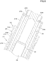
- FIG. 6 shows the first lock member 33 in the locking position.
- the tapered portion 33B of the first lock member 33 is pushed between the insertion portion 27A and the inner sleeve 27B.
- the first lock member 33 regulates the relative movement of the outer sleeve 27A and the inner sleeve 27B by a wedge effect. This allows the steering shaft 26 to be locked to an adjusted length.
- FIG. 7 shows the most lifted position, which is the position at which the first lock member 33 is displaced most upwardly from the locking position.
- the first lock member 33 is displaced upwardly from the locking position with respect to the insertion portion 27a and the inner sleeve 27B.
- a gap is created between the insertion portion 27A and the taper portion 33B, the wedge effect is released, and the relative movement of the outer sleeve 27A and the inner sleeve 27B is permitted. This allows the steering shaft 26 to stretch and shorten, and the length of the steering shaft 26 can be adjusted.
- the first side wall portion 22B is pivoted to the first bracket 21L via the first tilt axis (a tilting axis) 25L.
- the middle portion in the vertical direction of the first side wall portion 22B is supported on the upper rear side of the first bracket 21L, rotatably around the axis center of the first tilt axis 25L (tilt axis center XI).
- the second side wall 22C is pivoted to the first bracket 21L via the second tilt axis (tilting axis) 25R. More specifically, the second tilt axis 25R inserts the lower portion of the second side wall 22C and the rear portion of the lower portion of the second bracket 21R.
- the second tilt shaft 25R is detachable by screwing on a nut 66 (by fitting the screws together).
- the lower portion of the second bracket 21R is rotatably supported on the second bracket 21R around the axis center of the second tilt axis 25R (tilt axis center XI).
- the movable bracket 22 is rotatably supported by the first tilt shaft 25L and the second tilt shaft 25R on the fixed bracket 21 around the tilt axis X1.
- This allows the steering shaft 26 to tilt (incline) around the tilt axis center X1.
- the first tilt axis 25L and the second tilt axis 25R (tilt axis) are the centers of the tilt movement (tilt motion) of the steering shaft 26, and the steering shaft 26 can be adjusted for the tilt angle (tilt adjustment) around the tilt axis center X1.
- a support plate 34 is provided on the inside (right side) of the first side wall portion 22B.
- a first tilt axis 21L is fixed to the upper portion of the support plate 34.
- the first tilt axis 21L inserts through the first side wall 22B and also inserts through the first bracket 21L.
- the first tilt shaft 21L is detached by a nut 35 being screwed on.
- a support shaft 36 is fixed to the mid and front portion of the support plate 34 in the vertical direction.
- the support shaft 36 is inserted into the first bracket 21L.
- the support shaft 36 is detachable by a nut 37 being screwed on.
- the support plate 34 is fixedly attached to the first bracket 21L by the first tilt shaft 21L and nut 35 and by the support shaft 36 and nut 37.
- the tractor 1 has a tilt lock portion 61 that locks the steering shaft 26 at an adjusted tilt angle.
- the tilt lock portion 61 includes a first engagement portion 24, a lock member (referred to as a second lock member) 40, and a lock member 43.
- the first engagement portion 24 is formed at a lower end portion of the first side wall portion 22B.
- the first engagement portion 24 includes a plurality of engagement teeth 24a.
- the plurality of engagement teeth 24a are formed in an arc direction about the tilt axis center X1.
- a regulator hole 38 is formed between the first tilt axis 21L and the first engagement portion 24 in the first side wall 22B.
- the regulator hole 38 is formed through the first sidewall portion 22B and is formed in a long hole with an arc shape centered on the tilt axis X1.
- a regulator pin 39 is inserted into the regulator hole 38.
- the regulator pin 39 is fixed to the support plate 34.
- the movable bracket 22 is tiltable to the extent that the regulatory pin 39 moves relative to the regulator hole 38 from one end to the other.
- the second lock member 40 is arranged below the first side wall 22B. As shown in FIG. 3 and FIG. 4 , the second lock member 40 is arranged between the first bracket 21L and the support plate 34. The second lock member 40 is rotatably supported around an axis whose front portion extends in the vehicle width direction on the support axle 36. A second engagement portion 41 with a plurality of engagement teeth 41a is formed at the top end portion of the second lock member 40. The second engagement portion 41 is capable of engaging the first engagement portion 24.
- the plurality of engagement teeth 41a are formed in an arc direction around the tilt axis X1 in a state where the second engagement portion 41 is engaged with the first engagement portion 24.
- the engagement of the engagement tooth 24a of the first engagement 24 and the engagement tooth 41a of the second engagement 41 regulates the pivoting of the movable bracket 22 and allows the steering shaft 26 to be locked to an adjusted tilt angle.
- the second lock member 40 is pivoted downward and the second engagement portion 41 is released from the first engagement portion 24, allowing the pivoting of the movable bracket 22 and allowing the tilt angle of the steering shaft 26 to be adjusted.
- a downwardly opening engagement groove 42 is formed at the rear bottom of the second lock member 40.
- a lock member 43 is arranged below the rear portion of the second lock member 40.
- the lock member 43 is arranged between the first bracket 21L and the support plate 34 and is supported on a pivot shaft 44 with an axial center extending in the vehicle width direction at the midpoint.
- the pivot shaft 44 is fixed to the release arm 68, which will be described below, and intercepts the first bracket 21L, the lock member 43 and the first side wall 22B.
- the pivot shaft 44 is detached by a nut 45 being screwed on.
- the pivot shaft 44 is rotatable with respect to the first bracket 21L and the first side wall portion 22B.
- the lock member 43 is integrally rotatably fitted to the pivot shaft 44.
- the lock member 43 and the release arm 68 rotate integrally with the pivot axis 44.
- the lock member 43 includes an engaging portion 43a on the upper side and a spring-hanger portion 43b on the lower side.
- the engaging portion 43a is capable of engaging with the engagement groove 42.
- One end of a spring member 46 including a tensioned coil spring is fastened to the spring-hanger portion 43b.
- the other end portion of the spring member 46 is fastened to the spring-hanger portion 34a provided at the front portion of the support plate 34.
- the spring member 46 distributes the engagement member 43 in a direction that causes the engagement portion 43a to pivot backward.
- FIG 8 shows a tilt-locked state in which the second engagement portion 41 is engaged with the first engagement portion 24.
- the engagement portion 43a engages the lower rear surface of the engagement groove 42. This regulates the downward pivoting of the second lock member 40 and maintains the engagement of the second engagement portion 41 with the first engagement portion 24.
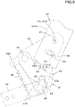
- the release arm 68 pivots downward from this state, the engagement member 43 pivots against the force of the spring member 46 so that the engagement portion 43a moves forward, as shown in FIG. 9 .
- the engagement portion 43a then moves out of the rear lower portion of the engagement groove 42 and toward the rear portion of the engagement groove 42. This causes the second lock member 40 to pivot downward, and the second engagement portion 41 is removed from the first engagement portion 24, allowing the tilt angle of the steering shaft 26 to be adjusted.
- an operation pedal (operation member) 47 is provided on the side of the first bracket 21L.
- the operation pedal 47 is arranged on the rear portion of the support member 30 and on the side (left side) of the lower portion of the first bracket 21L.
- the operation pedal 47 is linked to the tilt lock portion 61 and the telescopic lock portion 20 by an interlocking mechanism 49 to perform the unlocking operation by the tilt lock portion 61 and the telescopic lock portion 20. That is, the unlocking operation by the tilt lock portion 61 and the telescopic lock portion 20 can be performed by a single operation pedal 47.
- the operation pedal 47 is supported on a bracket member (referred to as the pedal bracket) 48.
- the pedal bracket 48 is located to the left of the lower portion of the first bracket 21 L and is fixed to the rear portion of the support member 30.
- the pedal bracket 48 is provided with a rotation shaft 62 having an axial center extending in the vehicle width direction that can be rotated around the axial center.
- the operation pedal 47 is fixed at the front portion of the operation pedal 47 so that the front portion can be rotated integrally with the rotation shaft 62.
- the operation pedal 47 includes a step portion 47a at the rear for an operator to step on.
- the interlocking mechanism 49 includes a first interlocking portion 49A, which interlocks the operation member 47 and the tilt lock portion 61, and a second interlocking portion 49B, which interlocks the first interlocking portion 49A with the telescopic lock portion 20.
- the first interlocking portion 49A includes an interlocking arm 67, an interlocking linkage 70, and a release arm 68.
- the interlocking arm 67 is connected at one end (front) to a rotation shaft 62 and is supported vertically pivotally on the pedal bracket 48 via the rotation shaft 62.
- the interlocking arm 67 pivots up and down in synchronization with the operation pedal 47.
- a hooking hole 73 is formed in the middle portion of the interlocking arm 67.
- one end side of the return spring 74 made up of a tension coil spring is hooked.
- the other end portion of the return spring 74 is fastened to a bracket member 75 fixed to the rear portion of the support member 30.
- a hooking hole 76 is formed at the bottom of the bracket member 75, and the other end portion of the return spring 74 is hooked in the hooking hole 76.
- the force of the return spring 74 forces the interlocking arm 67 and the operation pedal 47 to pivot upward.
- the upward rocking of the interlocking arm 67 and the operation pedal 47 and the like is regulated by the relay arm 69, which will be described below, coming into contact with the stopper portion 21a provided in the first bracket 21L, and the operation pedal 47 is held at the first position Y1 (non-pressed position), which is the position before the operation pedal 47 is operated (pressed).
- the interlocking linkage 70 is formed by a cylindrical rod material, and one end portion (lower end portion) 70a is connected to the other end (rear) of the interlocking arm 67.
- the one-end portion 70a includes an axial center extending in the vehicle width direction and is connected to the interlocking linkage 70 freely for rotation around the axial center.
- the other end side portion (upper end portion) 70b of the interlocking linkage 70 is connected to one end (front) of the release arm 68.
- the other end side portion 70b includes an axial center extending in the vehicle width direction and is rotatably connected to the release arm 68 around the axial center.
- the release arm 68 is arranged above the interlocking arm 67, and the other end (rear) side is pivoted to the first bracket 21L via a pivoting shaft 44.
- the release arm 68 is pulled down and pivoted downward via the interlocking arm 67 and the interlocking linkage 70 by depressing the control pedal 47.
- the lock member 43 pivots in conjunction with the downward pivoting of the release arm 68, causing the second engagement portion 41 to disengage from the first engagement portion 24 and unlock the lock by the tilt lock portion 20.
- the release arm 68 releases the lock by the tilt lock portion 20 in conjunction with the operation of the operation pedal 47.
- the second interlocking portion 49B includes a first relay linkage 71, a relay arm 69, a second relay linkage 72, and a working member 51.
- the relay arm 69 is interlocked with the release arm 68 by the first relay linkage 71, and is interlocked with the working member 51 by the second relay link.
- the first relay linkage 71 is formed of a cylindrical rod material, and one end portion (lower end portion) 71a is connected to the release arm 68.
- the one-end portion 71a includes an axial center extending in the vehicle width direction and is rotatably connected to the front portion of the release arm 68 around the axial center.
- One end side portion 71a of the first relay linkage 71 is located forward of the other end portion 70b of the interlocking linkage 70.
- the other end side portion (upper end side portion) 71b of the first relay linkage 71 is connected to the one end (front) side of the relay arm 69.
- the other end side portion 71b includes an axial center extending in the vehicle width direction and is rotatably connected to the relay arm 69 around the axial center.
- the relay arm 69 is located above the release arm 68 and is pivoted to the first bracket 21L at the midpoint.
- a support cylinder 77 is fixed to the upper portion of the first bracket 21L, and the relay arm 69 is attached to this support cylinder 77 via an attachment member 78.
- the attachment member 78 includes an axial center X4 extending in the vehicle width direction, and the relay arm 69 is rotatably supported around the axial center of the attachment member 78.
- a backlash groove (mechanical play portion) 79 is formed on the other end (rear) of the relay arm 69.
- the backlash groove 79 is formed in a long groove that is long in the vertical direction and arc-shaped around the axis center X4 of the attachment member 78.
- the second relay linkage 72 is formed of a cylindrical rod material, and one end side portion (lower end portion) 72a is inserted into the backlash groove 79.
- the one-end portion 72a includes an axial center extending in the vehicle width direction and is inserted in the backlash groove 79, rotatable around the axial center and movable between one end and the other end in the longitudinal direction of the groove.
- the other end portion (upper end portion) 72b of the second relay linkage 72 is connected to the working member 51.
- the other end side portion 72b includes an axial center extending in the vehicle width direction and is rotatably connected to the working member 51 around the axial center.
- the working member 51 supports the first lock member 33 in a movable manner up and down.
- the working member 51 is linked to the operation pedal 47 via the first interlocking portion 49A, the first relay linkage 71, the relay arm 69, and the second relay linkage 72, which unlocks the lock by the telescopic lock portion 20 in conjunction with the operation of the operation pedal 47.
- the working member 51 includes a first member 52 and a second member 53.
- the first member 52 includes a first portion 52a located to the left of the first lock member 33, a second portion 52b extending posteriorly downward from the lower rear end portion of the first portion 52a, and a third portion 52c extending rightward from the rear end portion of the second portion 52b.
- the first portion 52a includes a guide groove 54 at the top and a boss 55 at the bottom.
- a roller 56 is fitted in the guide groove 54 with the roller 56 free to rotate around an axis extending in the vehicle width direction and free to move in the longitudinal direction of the groove.
- a pin 57 fixed to the upper portion 33A of the first lock member 33 is inserted into the roller 56.
- the boss 55 is located in the lower front portion of the guide groove 54.
- An insertion hole 58 is formed in the second portion 52B. In this insertion hole 58, the other end portion 72b of the second relay linkage 72 is inserted into the insertion hole 58.
- the second member 53 includes a first portion 53a located to the right of the first lock member 33, a second portion 53b extending posteriorly downward from the lower rear end portion of the first portion 53a, and a third portion 53c extending leftward from the rear end portion of the second portion 53b.
- the first portion 53a includes a guide groove 54 at the top and a boss 55 at the bottom.
- the roller 56 is fitted in the guide groove 54 with the roller 56 free to rotate around an axis extending in the vehicle width direction and free to move in the longitudinal direction of the groove.
- the pin 57 fixed to the upper portion 33A of the first lock member 33 is inserted into the roller 56 with relative rotational freedom.
- the boss 55 is located below the front portion of the guide groove 54.
- the third portion 52c and the third portion 53c are connected by a fastener tool 59 having a bolt and nut.
- the boss 55 is attached to the upper portion of the outer sleeve 27A by an attachment member 60.
- the attachment member 60 includes an axial center X2 extending in the vehicle width direction, and the working member 51 is supported on the outer sleeve 27A by the outer sleeve 27A, which can be pivoted up and down around the axial center X2 of the attachment member 60.
- the guide groove 54 includes a lock portion 54a and an unlock portion 54b.
- the lock portion 54a is formed in an arc of radius R1 centered on the axial center X2 of the attachment member 60
- the unlock portion 54b is formed in an arc of radius R2 centered on the arc center X3, which is different from the axial center X2.
- the arc center X3 is a line extending in the vehicle width direction and is located behind and below the axial center X2.
- the leftmost view in FIG. 13 shows the first lock member 33 in the locking position.
- the roller 56 is located in the lock portion 54a of the guide groove 54.
- the working member 51 pivots upwardly about the axis center X2 and pushes the roller 56 up at the lower end portion of the unlock portion 54b, as shown in the center view in FIG. 13 .
- This causes the first lock member 33 to move upward.
- the first lock member 33 moves upward until the roller 56 reaches the rear end portion of the guide groove 54, as shown in the rightmost view in FIG. 13 , and the first lock member 33 is in the most lifted position.
- the wedge effect by the first lock member 33 is released and the steering shaft 26 becomes adjustable in length.
- FIG. 11 shows the state before operating the operation pedal 47, and the operation pedal 47 is in the first position Y1.
- the tilt lock portion 61 is in a locking state and the telescopic lock portion 20 is also in a locking state. That is, the steering shaft 26 is non-tiltable and non-retractable.
- the operation pedal 47 located in the first position Y1
- the one end side portion 72a of the second relay linkage 72 is located at the upper end portion of the backlash groove 79.
- the one end side portion 72a of the second relay linkage 72 is located near (the tilt axis) of the first tilt axis 21L and the second tilt axis 21R in side view.
- the second relay linkage 72 pivots integrally with the steering shaft 26, but since one end side portion 72a of the second relay linkage 72 is located near the first tilt shaft 21L and the second tilt shaft 21R in side view, the second relay linkage 72 is allowed to pivot integrally with the steering shaft 26 due to the relative rotation and rattling between the one end side portion 72a and the backlash groove 79 and due to the relative rotation and rattling between the other end side portion 72b and the insertion hole 58.
- the backlash groove 79 is a backlash groove that does not interlock the first interlocking portion 49A and the telescopic lock portion 20 until a predetermined amount of operation is performed from the position before operating the operation pedal 47.
- the operation pedal 47 When the operation pedal 47 is operated from the first position Y1 to the second position Y2 shown in FIG. 14 , the lock is released by the tilt lock portion 61 but not by the telescopic lock portion 20. That is, the operation pedal 47 includes a second position Y2 that is operated from the first position Y1, which unlocks with the tilt lock portion 61 and does not unlock with the telescopic lock portion 20.
- This second position Y2 is an arbitrary position within the operating range (operating area) of the operation pedal 47 between the position where the lock is released by the tilt lock portion 61 and the position before the position where the lock is released by the telescopic lock portion 20.
- the second relay linkage 72 moves upward in conjunction with the upward swinging of the rear portion of the relay arm 69, as shown in FIG. 15 .
- the second relay linkage 72 moves upward. This causes the working member 51 to pivot upwardly around the attachment member 60 and pushes up the first lock member 33.
- the first lock member 33 is lifted up to the highest lifted position by the upward movement of the second relay linkage 72 and the upward oscillation of the working member 51.
- the operation pedal 47 includes a third position Y3, which is the position operated from the second position Y2 and which unlocks by the tilt lock portion 61 and the telescopic lock portion 20.
- the third position Y is an arbitrary position within the operating range of the operation pedal 47, which is included in the operating region after the wedge effect by the first lock member 33 has been released.
- the operation pedal 47 includes an operating region for both unlocking by the tilt lock portion 61 and unlocking by the telescopic lock portion 20.
- the operation pedal 47 When releasing both the lock by the tilt lock portion 61 and the lock by the telescopic lock portion 20, the operation pedal 47 is usually depressed to the maximum extent.
- a single operation pedal 47 can operate the tilt lock portion 61 and the telescopic lock portion 20 and can select one of the two adjustment patterns where only the tilt adjustment of the steering shaft 26 is performed and where both the tilt adjustment and length adjustment of the steering shaft 26 are performed.
- the selection of these adjustment patterns can be performed by a single operating pedal 47, which is convenient.
- the tilt adjustment and length adjustments are necessary. In such a case, a case for both of the tilt and length adjustments can be selected.
- the position of the backlash groove is not limited to that of the present embodiment, but may be provided in the working member 51, for example. That is, the guide groove 54 may be formed in the shape of an arc around the axial center X2 of the attachment member 60, and the guide groove 54 may be used as a mechanical play area. In this case, after the roller 56 moves to the back end portion of the guide groove 54, the working member 51 pivots upward to release the lock by the telescopic lock portion 20.
- the tractor (traveling vehicle) 1 includes the steering shaft 26 to which the steering handle 19 is attached, the steering shaft 26 that is adjustable in tilt angle and length, the tilt lock portion 61 that locks the steering shaft 26 to the adjusted tilt angle, the telescopic lock portion 20 which locks the steering shaft 26 to an adjusted length, and the operation member 47 which includes an operation area allowing locking of both of the tilt lock portion 61 and the telescopic lock portion 20 to be released.
- the releasing both of the lock by the tilt lock portion 61 and the lock by the telescopic lock portion 20 can be performed by the operation member 47, and the operability of adjusting the length and tilt angle of the steering shaft 26 can be improved.
- the operation member 47 includes the first position Y1 which is the position before the operation, the second position Y2 which is the position operated from the first position Y1 and which unlocks with the tilt lock portion 61 and does not unlock with the telescopic lock portion 20, and the third position Y3 which is the position operated from the second position Y2 and which unlocks with the tilt lock portion 61 and the telescopic lock portion 20.
- the tractor 1 includes an interlocking mechanism 49 to interlock the operation member 47 with the tilt lock portion 61 and the telescopic lock portion 20.
- the interlocking mechanism 49 includes the first interlocking portion 49A for interlocking the operation member 47 and the tilt lock portion 61, the second interlocking portion 49B for interlocking the first interlocking portion 49A with the telescopic lock portion 20, and a mechanical play portion (backlash groove 79) that does not interlock the first interlocking portion 49A and the telescopic lock portion 20 until a predetermined amount of operation is performed from the position before the operation of the operation member 47.
- first interlocking portion 49A includes the release arm 68 to release the lock by the tilt lock portion 61 in conjunction with operation of the operation member 47.
- second interlocking portion 49B includes a working member 51 to release the lock by the telescopic lock portion 20 in conjunction with operation of the operation member 47, and the relay arm 69 interlocked with the release arm 68 by the first relay linkage 71 and interlocked with the working member 51 by the second relay linkage 72.
- the mechanical play portion (backlash groove 79) is provided to the relay arm 69 and formed of a long groove to which one end portion 72a of the second relay linkage 72 is inserted, and the one end portion 72a relatively moves in the groove to prevent the relay arm 69 and the moving member 51 from being interlocked each other until the operation member 47 is moved in a predetermined distance, and further moves after the operation member 47 is moved in the predetermined distance such that an end portion of the long groove contacts to the one end portion 72a to interlock the relay arm 69 and the moving member 51.
- a structure that allows for the tilt and length adjustments of the steering shaft 26 with a single operation member 47 can be further easily configured.
- the tractor 1 is provided with the tilt axis (first tilt axis 21L, second tilt axis 21R), which is the center of the tilt movement of the steering shaft 26.
- the center of the axis of the tilt axis (tilt axis center XI) of the tilt axis coincides with the center of one end portion 72a of the second relay linkage 72 in a state where the tilt angle of the steering shaft 26 can be adjusted and the length of the steering shaft 26 can be adjusted.
- the tilt adjustment can be performed smoothly.
Landscapes
- Engineering & Computer Science (AREA)
- Chemical & Material Sciences (AREA)
- Combustion & Propulsion (AREA)
- Transportation (AREA)
- Mechanical Engineering (AREA)
- Steering Controls (AREA)
Abstract
Description
- The present invention relates to a traveling vehicle such as a tractor.
- A traveling vehicle disclosed in Patent Document 1 is known.
- The traveling vehicle disclosed in Patent Document 1 includes a steering shaft to which a steering wheel is attached. The steering shaft is adjustable in tilt angle as well as in a length. The traveling vehicle also includes a tilt lock portion that locks the steering shaft at an adjusted tilt angle and a telescopic lock portion that locks the steering shaft to an adjusted length.
- [Patent Document 1]
Japanese Unexamined Patent Publication No. 2017-87953 - In the traveling vehicle disclosed in Patent Document 1, releasing lock of the steering shaft by the tilt lock portion and releasing lock of the steering shaft by the telescopic lock portion are respectively performed by different levers, that is, adjusting the tilt angle of the steering shaft and adjusting the length of the steering shaft need to be respectively performed in different operations. That is, the adjustment of the tilt angle and length of the steering shaft had to be performed in different operations. As a result, it causes a problem that deteriorates operability of adjusting the tilt angle and length of the steering shaft.
- Accordingly, in view of the problems mentioned above, the present invention is intended to improve operability of adjusting the tilt angle and length of the steering shaft.
- A traveling vehicle according to one aspect of the present invention, includes: a steering shaft to which a steering handle is attached, the steering shaft having a tilt angle and a length both adjustable; a tilt lock to lock the steering shaft at an adjusted tilt angle; a telescopic lock to lock the steering shaft at an adjusted length; and an operation member including an operation area allowing locking of both of the tilt lock and the telescopic lock to be released.
- In addition, the operation member has: a first position at which the operation member is not moved; a second position at which the operation member is moved from the first position, the second position allowing locking of the tilt lock to be released and preventing locking of the telescopic lock from being released; and a third position at which the operation member is further moved from the second position, the third position allowing locking of the tilt lock and the telescopic lock to be released.
- In addition, the traveling vehicle mentioned above includes an interlocking mechanism to interlock the operation member with the tilt lock and the telescopic lock. The interlocking mechanism includes: a first interlocking to interlock the operation member and the tilt lock; a second interlocking to interlock the first interlocking and the telescopic lock; and an mechanical play preventing the first interlocking and the telescopic lock from being interlocked each other until the operation member is moved in a predetermined distance from a position at which the operation member is not moved.
- In addition, the first interlocking includes a release arm to be moved in synchronization with operation of the operation member to release locking of the tilt lock. The second interlocking includes: a moving member to be moved in synchronization with the operation of the operation member to release locking of the telescopic lock; and a relay arm interlocked with the release arm by a first relay linkage and interlocked with the moving member by the second relay linkage, the mechanical play is provided to the relay arm and formed of a groove to which one end portion of the second relay linkage is inserted, and the one end portion relatively moves in the groove to prevent the relay arm and the moving member from being interlocked each other until the operation member is moved in a predetermined distance, and further moves after the operation member is moved in the predetermined distance such that an end portion of the groove contacts to the one end portion to interlock the relay arm and the moving member.
- In addition, the traveling vehicle mentioned above includes a tilt shaft serving as a center of an inclining movement of the steering shaft. A center of the one end portion of the second relay linkage coincides with an axis of the tilt shaft under a state where the tilt angle of the steering shaft can be adjusted and the length of the steering shaft can be adjusted.
- According to the present invention, an operation member is capable of both releasing lock by a tilt lock portion and releasing lock by a telescopic lock portion. In this configuration, operability of adjusting a length and tilt angle of a steering shaft can be improved.
-
-
FIG. 1 is a perspective view of an operation device seen from a back surface. -
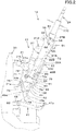
FIG. 2 is a side view of an operation device. -
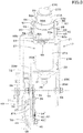
FIG. 3 is a back view of an upper portion of an operation device. -
FIG. 4 is an exploded perspective view of an operation console. -
FIG 5 is a side cross-section view of a lower portion of a steering shaft. -
FIG. 6 is an enlarged cross-section view illustrating a state where a steering shaft is locked in an adjusted length. -
FIG. 7 is an enlarged cross-section view illustrating a state where locking of a steering shaft in a longitudinal direction is released. -
FIG. 8 is a side view of a lock portion in which a steering shaft is locked at an adjusted tilt angle. -
FIG. 9 is a side view illustrating a state where locking of a tilt angle of a steering shaft is released. -
FIG. 10 is a perspective view of an interlocking mechanism. -
FIG. 11 is a side view of an interlocking mechanism. -
FIG. 12 is a side view of a working member. -
FIG. 13 is a side view illustrating an operation state of a telescopic lock portion. -
FIG 14 is a side view of an interlocking mechanism in a case where an operation pedal is operated to a second position. -
FIG. 15 is a side view of an interlocking mechanism in a case where an operation pedal is further operated from a second position. -
FIG. 16 is a side view of an interlocking mechanism in a case where an operation pedal is operated to a third position. -
FIG. 17 is a side view of a traveling vehicle. - Hereinafter, an embodiment of the present invention will be described with appropriate reference to the drawings.
-
FIG. 17 is a schematic side view of a traveling vehicle in this embodiment. In this embodiment, a tractor 1 is illustrated as the traveling vehicle. - In this embodiment, a direction of an arrowed line A1 direction in
FIG. 17 (a forward direction of the tractor 1) is referred to as the front, and a direction of an arrowed line A2 inFIG. 17 (a backward direction of the tractor 1) is referred to as the rear. Thus, the front surface side ofFIG 17 is referred to the left, and the back surface side ofFIG. 17 is referred to the right. The horizontal direction orthogonal to the front-to-rear direction A3 is explained as a vehicle width direction. The direction from the center to the right or left portion of the vehicle width direction in tractor 1 is explained as the outside of the vehicle (also referred to as a vehicle outward direction). In other words, the vehicle outward direction is the direction in the vehicle width direction separating away from the center of the tractor 1. A direction opposite to the vehicle outward direction is explained as a vehicle inward direction (also referred to as a vehicle inward direction). In other words, the vehicle inward direction is the direction in the vehicle width direction approaching closer to the center of the tractor 1. - As shown in
FIG. 17 , the tractor 1 has avehicle body 2. Thevehicle body 2 has a prime mover E1, a flywheel housing 3, aclutch housing 4, atransmission case 5, and a front axle frame 6. - The prime mover E1 is a diesel engine. The prime mover E1 is located at the front portion of the tractor 1 and is covered by a
bonnet hood 10. The prime mover E1 may be an electric motor or may be a hybrid type having a diesel engine and an electric motor. - The
flywheel housing 3 is connected to the rear portion of the prime mover E1 and houses the flywheel. Theclutch housing 4 is connected to the rear portion of theflywheel housing 3 and houses a clutch that intermittently transmits power of the prime mover E1 transmitted through the flywheel. Thetransmission case 5 is connected to the rear portion of theclutch housing 4 and houses a transmission for changing the power transmitted through the clutch. The transmission includes a forward/backward switching mechanism for switching the power transmitted by the transmission between a forward traveling output or a backward traveling output. - The front axle frame 6 is fixed to the prime mover E1 and protrudes forward from the prime mover E1. A
front axle case 15 is supported on the front axle frame 6. - As shown in
FIG. 17 , the tractor 1 has a travelingdevice 8 that supports thevehicle body 2 such that thevehicle body 2 can travel. The travelingdevice 8 is a wheel-type traveling device including a plurality offront wheels vehicle body 2 and including a plurality ofrear wheels vehicle body 2. The plurality of front wheels include a leftfront wheel 11L supported on the left side of thefront axle case 15 and a rightfront wheel 11R supported on the right side of thefront axle case 15. The plurality of rear wheels include a leftrear wheel 12L supported on the left side of thetransmission case 5 and a rightrear wheel 12R supported on the right side of thetransmission case 5. The travelingdevice 8 may be a semi-crawler type traveling device (a traveling device having a front wheel and a crawler-type traveling mechanism employed in place of the rear wheel). - The left
front wheel 11L and the rightfront wheel 11R are steerable wheels that can be steered by the movement of the cylinder rod of thesteering cylinder 16 located at the front portion of thefront axle case 15. By steering the leftfront wheel 11L and the rightfront wheel 11R, it is possible to change the orientation of the vehicle body 2 (the vehicle body can be steered). Thesteering cylinder 16 consists of a hydraulic cylinder. The steering device for steering thevehicle body 2 may be a hydraulic power steering device including thesteering cylinder 16 described above, or an electric power steering device that steers thefront wheels front wheels - At the rear portion of the
vehicle body 2 is anoperator seat 13 on which the driver (operator) is seated. In front portion of theoperator seat 13, asteering device 14 is provided to steer and operate thevehicle body 2. Thesteering device 14 is installed on the rear portion of thesupport member 30, which is erected on thevehicle body 2. Thesupport member 30 is arranged at the rear portion of thebonnet hood 10 and is a member that separates the interior of thebonnet hood 10 from the area where theoperator seat 13 and the pilotingdevice 14 are located. - The
steering device 14 includes the steering handle 19 for steering the vehicle body 2 (thefront wheels support frame 17 supporting thesteering handle 19, and thesteering cover 18 covering the operation console. - As shown in
FIG. 1 andFIG. 2 , thesupport frame 17 includes the fixedbracket 21 fixed to the rear portion of thesupport member 30 and themovable bracket 22 supported on the fixedbracket 21 that can be rotated (tilted) around an axial center extending in the vehicle width direction (a tilting axial center) X1. - As shown in
FIG. 3 andFIG. 4 , the fixedbracket 21 includes thefirst bracket 21L and thesecond bracket 21R. Thefirst bracket 21L and thesecond bracket 21R are formed of plate materials and are arranged at an interval in the vehicle width direction. As shown inFIG. 1 , thefirst bracket 21L is formed long in the vertical direction and is fixed to the rear portion of thesupport member 30 and the bottom end is fixed to the bottom of thesupport member 30. As shown inFIG. 3 , thesecond bracket 21R is arranged on the right side of the upper portion of thefirst bracket 21L. As shown inFIG. 1 , thesecond bracket 21R is secured to the rear portion of thesupport member 30. - As shown in
FIG. 4 , themovable bracket 22 is formed of a plate material and has anupper wall portion 22A, a firstside wall portion 22B fixed to the left end portion of theupper wall portion 22A, and a secondside wall portion 22C extended downwardly from the right end portion of theupper wall portion 22A. Theupper wall portion 22A includes an openingportion 23. The openingportion 23 is formed through theupper wall portion 22A. - As shown in
FIG. 2 andFIG 5 , themovable bracket 22 is provided with the steeringpost 27. On thesteering post 27, the steeringshaft 26 is supported by the steeringpost 27. The steering handle 19 is attached to the upper portion of the steering shaft 26 (seeFIG. 17 ). - As shown in
FIG 5 , the steeringpost 27 has anouter sleeve 27A, aninner sleeve 27B, and asupport cylinder 27C. The lower end portion of theouter sleeve 27A is fixed to theupper wall portion 22A. Theouter sleeve 27A surrounds the openingportion 23. Theinner sleeve 27B is inserted into theouter sleeve 27A. Theinner tube 27B is movable in the axial direction with respect to theouter tube 27A and is not rotatable around the axis by key coupling or otherwise. Anend plate 27D having a ring-disc shape is fixed to the upper end portion of theinner sleeve 27B. The bottom end portion of thesupport cylinder 27C is fixed to theend plate 27D. A support bushing 27E is inserted into the upper portion of thesupport cylinder 27C. - As shown in
FIG. 5 , the steeringshaft 26 includes afirst shaft 28 and asecond shaft 29. Thefirst shaft 28 is arranged in theinner sleeve 27B and the lower portion protrudes below theupper wall 22A through the openingportion 23. The lower portion of thefirst shaft 28 is rotatably supported around the axis by a bearingmember 31 fixed to theupper wall 22A. The bearingmember 31 includes an upper portion fixed to the inner surface of the openingportion 23 and protrudes downward from theupper wall 22A. The lower portion of thefirst shaft 29 protrudes downwardly from the bearingmember 31, and, for example, a steering valve is connected to this protrusion via a coupling. The steering valve is a rotary valve that is operated by the steeringshaft 26 to output hydraulic fluid to operate thesteering cylinder 16. The steering valve may not be directly connected to thefirst shaft 29. For example, the steering valve may be located below thesteering system 14 and interlocked with thefirst shaft 29 and the steering valve by a power transmission mechanism having a universal joint. - As shown in
FIG. 5 , thesecond shaft 29 includes a lowerlarge diameter portion 29A and an uppersmall diameter portion 29B. The large-diameter portion 29A is arranged in theinner sleeve 27B and is spline coupled to thefirst shaft 28. Thus, thesecond shaft 29 is axially movable with respect to thefirst shaft 28 and can be rotated integrally around the axis. In other words, the steeringshaft 26 is stretchable in the axial direction and can be adjusted in length by stretching and shortening. The upper end portion of the large-diameter portion 29A is in contact with theend plate 27D. The small-diameter portion 29B protrudes upwardly from theend plate 27D and inserts the support bushing 27E. The small-diameter portion 29B is rotatably supported by the support bushing 27E around the axis. The steering handle 19 is mounted on the upper portion of the small-diameter portion 29B. - The small-
diameter portion 29B regulates the downward movement with respect to the support bushing 27E with theretainer ring 32. The large-diameter portion 29A is in contact with theend plate 27D, and the upward movement is regulated by theend plate 27D. Thus, thesecond shaft 29 moves integrally with theinner sleeve 27B and thesupport cylinder 27C. - As shown in
FIG. 2 andFIG. 5 , the tractor 1 includes atelescopic lock portion 20 that locks the steeringshaft 26 in an adjusted length. Thetelescopic lock portion 20 includes a locking member (referred to as the first lock member) 33 that regulates the stretching and shortening of the steeringshaft 26. - As shown in
FIG. 6 , thefirst lock member 33 is provided at the upper portion of theouter sleeve 27A. Thefirst lock member 33 is formed in a cylindrical shape and is fitted to the outside of theinner sleeve 27B in an axial direction relative to the axial direction (vertical movement is possible). Thefirst lock member 33 is formed in a cylindrical shape with theupper portion 33A. Thefirst lock member 33 has the taperedportion 33B at the bottom. The taperedportion 33B is formed on a tapered surface whose outer surface shape becomes progressively smaller in diameter (gradually decreasing in diameter) as shifting downwardly, and is formed in the shape of an externally cone shape. - As shown in
FIG. 5 andFIG. 6 , thetelescopic lock portion 20 includes aninsertion portion 27a with which the taperedportion 33B of thefirst lock member 33 engages. Theinsertion portion 27a is formed in the upper portion of theouter sleeve 27A. Theinsertion portion 27A is formed on a tapered surface whose inner surface shape becomes progressively larger in diameter (gradually enlarging in diameter) as shifting upward. -
FIG. 6 shows thefirst lock member 33 in the locking position. In this state, the taperedportion 33B of thefirst lock member 33 is pushed between theinsertion portion 27A and theinner sleeve 27B. Thus, in the locking position, thefirst lock member 33 regulates the relative movement of theouter sleeve 27A and theinner sleeve 27B by a wedge effect. This allows the steeringshaft 26 to be locked to an adjusted length. -
FIG. 7 shows the most lifted position, which is the position at which thefirst lock member 33 is displaced most upwardly from the locking position. In this most lifted position, thefirst lock member 33 is displaced upwardly from the locking position with respect to theinsertion portion 27a and theinner sleeve 27B. Thus, in the lifted position, a gap is created between theinsertion portion 27A and thetaper portion 33B, the wedge effect is released, and the relative movement of theouter sleeve 27A and theinner sleeve 27B is permitted. This allows the steeringshaft 26 to stretch and shorten, and the length of the steeringshaft 26 can be adjusted. - As shown in
FIG. 4 , the firstside wall portion 22B is pivoted to thefirst bracket 21L via the first tilt axis (a tilting axis) 25L. In detail, the middle portion in the vertical direction of the firstside wall portion 22B is supported on the upper rear side of thefirst bracket 21L, rotatably around the axis center of thefirst tilt axis 25L (tilt axis center XI). Thesecond side wall 22C is pivoted to thefirst bracket 21L via the second tilt axis (tilting axis) 25R. More specifically, thesecond tilt axis 25R inserts the lower portion of thesecond side wall 22C and the rear portion of the lower portion of thesecond bracket 21R. Thesecond tilt shaft 25R is detachable by screwing on a nut 66 (by fitting the screws together). The lower portion of thesecond bracket 21R is rotatably supported on thesecond bracket 21R around the axis center of thesecond tilt axis 25R (tilt axis center XI). - As described above, the
movable bracket 22 is rotatably supported by thefirst tilt shaft 25L and thesecond tilt shaft 25R on the fixedbracket 21 around the tilt axis X1. This allows the steeringshaft 26 to tilt (incline) around the tilt axis center X1. Thefirst tilt axis 25L and thesecond tilt axis 25R (tilt axis) are the centers of the tilt movement (tilt motion) of the steeringshaft 26, and the steeringshaft 26 can be adjusted for the tilt angle (tilt adjustment) around the tilt axis center X1. - As shown in
FIG. 3 andFIG. 4 , asupport plate 34 is provided on the inside (right side) of the firstside wall portion 22B. Afirst tilt axis 21L is fixed to the upper portion of thesupport plate 34. Thefirst tilt axis 21L inserts through thefirst side wall 22B and also inserts through thefirst bracket 21L. Thefirst tilt shaft 21L is detached by anut 35 being screwed on. - A
support shaft 36 is fixed to the mid and front portion of thesupport plate 34 in the vertical direction. Thesupport shaft 36 is inserted into thefirst bracket 21L. Thesupport shaft 36 is detachable by anut 37 being screwed on. Thesupport plate 34 is fixedly attached to thefirst bracket 21L by thefirst tilt shaft 21L andnut 35 and by thesupport shaft 36 andnut 37. - As shown in
FIG. 3 andFIG. 4 , the tractor 1 has atilt lock portion 61 that locks the steeringshaft 26 at an adjusted tilt angle. Thetilt lock portion 61 includes afirst engagement portion 24, a lock member (referred to as a second lock member) 40, and alock member 43. - As shown in
FIG. 4 andFIG. 8 , thefirst engagement portion 24 is formed at a lower end portion of the firstside wall portion 22B. Thefirst engagement portion 24 includes a plurality ofengagement teeth 24a. The plurality ofengagement teeth 24a are formed in an arc direction about the tilt axis center X1. Aregulator hole 38 is formed between thefirst tilt axis 21L and thefirst engagement portion 24 in thefirst side wall 22B. Theregulator hole 38 is formed through thefirst sidewall portion 22B and is formed in a long hole with an arc shape centered on the tilt axis X1. Aregulator pin 39 is inserted into theregulator hole 38. Theregulator pin 39 is fixed to thesupport plate 34. Thus, themovable bracket 22 is tiltable to the extent that theregulatory pin 39 moves relative to theregulator hole 38 from one end to the other. - As shown in
FIG. 8 , thesecond lock member 40 is arranged below thefirst side wall 22B. As shown inFIG. 3 andFIG. 4 , thesecond lock member 40 is arranged between thefirst bracket 21L and thesupport plate 34. Thesecond lock member 40 is rotatably supported around an axis whose front portion extends in the vehicle width direction on thesupport axle 36. Asecond engagement portion 41 with a plurality ofengagement teeth 41a is formed at the top end portion of thesecond lock member 40. Thesecond engagement portion 41 is capable of engaging thefirst engagement portion 24. The plurality ofengagement teeth 41a are formed in an arc direction around the tilt axis X1 in a state where thesecond engagement portion 41 is engaged with thefirst engagement portion 24. The engagement of theengagement tooth 24a of thefirst engagement 24 and theengagement tooth 41a of thesecond engagement 41 regulates the pivoting of themovable bracket 22 and allows the steeringshaft 26 to be locked to an adjusted tilt angle. - As shown in
FIG 9 , thesecond lock member 40 is pivoted downward and thesecond engagement portion 41 is released from thefirst engagement portion 24, allowing the pivoting of themovable bracket 22 and allowing the tilt angle of the steeringshaft 26 to be adjusted. - As shown in
FIG. 8 , a downwardly openingengagement groove 42 is formed at the rear bottom of thesecond lock member 40. Alock member 43 is arranged below the rear portion of thesecond lock member 40. - As shown in
FIG 4 , thelock member 43 is arranged between thefirst bracket 21L and thesupport plate 34 and is supported on apivot shaft 44 with an axial center extending in the vehicle width direction at the midpoint. Thepivot shaft 44 is fixed to therelease arm 68, which will be described below, and intercepts thefirst bracket 21L, thelock member 43 and thefirst side wall 22B. Thepivot shaft 44 is detached by anut 45 being screwed on. Thepivot shaft 44 is rotatable with respect to thefirst bracket 21L and the firstside wall portion 22B. Thelock member 43 is integrally rotatably fitted to thepivot shaft 44. Thus, thelock member 43 and therelease arm 68 rotate integrally with thepivot axis 44. - As shown in
FIG. 8 , thelock member 43 includes an engagingportion 43a on the upper side and a spring-hanger portion 43b on the lower side. The engagingportion 43a is capable of engaging with theengagement groove 42. One end of aspring member 46 including a tensioned coil spring is fastened to the spring-hanger portion 43b. The other end portion of thespring member 46 is fastened to the spring-hanger portion 34a provided at the front portion of thesupport plate 34. Thespring member 46 distributes theengagement member 43 in a direction that causes theengagement portion 43a to pivot backward. -
FIG 8 shows a tilt-locked state in which thesecond engagement portion 41 is engaged with thefirst engagement portion 24. In this tilt-locked state, theengagement portion 43a engages the lower rear surface of theengagement groove 42. This regulates the downward pivoting of thesecond lock member 40 and maintains the engagement of thesecond engagement portion 41 with thefirst engagement portion 24. When therelease arm 68 pivots downward from this state, theengagement member 43 pivots against the force of thespring member 46 so that theengagement portion 43a moves forward, as shown inFIG. 9 . Theengagement portion 43a then moves out of the rear lower portion of theengagement groove 42 and toward the rear portion of theengagement groove 42. This causes thesecond lock member 40 to pivot downward, and thesecond engagement portion 41 is removed from thefirst engagement portion 24, allowing the tilt angle of the steeringshaft 26 to be adjusted. - When the
release arm 68 is pivoted upward, thesecond engagement portion 41 engages thefirst engagement portion 24 in the opposite action with respect to the above description. - As shown in
FIG. 1 andFIG. 17 , an operation pedal (operation member) 47 is provided on the side of thefirst bracket 21L. In detail, theoperation pedal 47 is arranged on the rear portion of thesupport member 30 and on the side (left side) of the lower portion of thefirst bracket 21L. - As shown in
FIG. 2 andFIG. 3 , theoperation pedal 47 is linked to thetilt lock portion 61 and thetelescopic lock portion 20 by an interlockingmechanism 49 to perform the unlocking operation by thetilt lock portion 61 and thetelescopic lock portion 20. That is, the unlocking operation by thetilt lock portion 61 and thetelescopic lock portion 20 can be performed by asingle operation pedal 47. - As shown in
FIG. 1 , theoperation pedal 47 is supported on a bracket member (referred to as the pedal bracket) 48. Thepedal bracket 48 is located to the left of the lower portion of thefirst bracket 21 L and is fixed to the rear portion of thesupport member 30. Thepedal bracket 48 is provided with arotation shaft 62 having an axial center extending in the vehicle width direction that can be rotated around the axial center. Theoperation pedal 47 is fixed at the front portion of theoperation pedal 47 so that the front portion can be rotated integrally with therotation shaft 62. Theoperation pedal 47 includes astep portion 47a at the rear for an operator to step on. - As shown in
FIG. 2 , the interlockingmechanism 49 includes afirst interlocking portion 49A, which interlocks theoperation member 47 and thetilt lock portion 61, and asecond interlocking portion 49B, which interlocks the first interlockingportion 49A with thetelescopic lock portion 20. - As shown in
FIG. 11 , the first interlockingportion 49A includes an interlockingarm 67, an interlockinglinkage 70, and arelease arm 68. - As shown in
FIG. 10 andFIG. 11 , the interlockingarm 67 is connected at one end (front) to arotation shaft 62 and is supported vertically pivotally on thepedal bracket 48 via therotation shaft 62. Thus, the interlockingarm 67 pivots up and down in synchronization with theoperation pedal 47. A hookinghole 73 is formed in the middle portion of the interlockingarm 67. In the hookinghole 73, one end side of thereturn spring 74 made up of a tension coil spring is hooked. The other end portion of thereturn spring 74 is fastened to abracket member 75 fixed to the rear portion of thesupport member 30. More specifically, a hookinghole 76 is formed at the bottom of thebracket member 75, and the other end portion of thereturn spring 74 is hooked in the hookinghole 76. The force of thereturn spring 74 forces the interlockingarm 67 and theoperation pedal 47 to pivot upward. - As shown in
FIG. 10 andFIG. 11 , the upward rocking of the interlockingarm 67 and theoperation pedal 47 and the like is regulated by therelay arm 69, which will be described below, coming into contact with thestopper portion 21a provided in thefirst bracket 21L, and theoperation pedal 47 is held at the first position Y1 (non-pressed position), which is the position before theoperation pedal 47 is operated (pressed). - As shown in
FIG. 10 andFIG. 11 , the interlockinglinkage 70 is formed by a cylindrical rod material, and one end portion (lower end portion) 70a is connected to the other end (rear) of the interlockingarm 67. In detail, the one-end portion 70a includes an axial center extending in the vehicle width direction and is connected to the interlockinglinkage 70 freely for rotation around the axial center. The other end side portion (upper end portion) 70b of the interlockinglinkage 70 is connected to one end (front) of therelease arm 68. In detail, the otherend side portion 70b includes an axial center extending in the vehicle width direction and is rotatably connected to therelease arm 68 around the axial center. - As shown in
FIG. 10 andFIG. 11 , therelease arm 68 is arranged above the interlockingarm 67, and the other end (rear) side is pivoted to thefirst bracket 21L via a pivotingshaft 44. Therelease arm 68 is pulled down and pivoted downward via the interlockingarm 67 and the interlockinglinkage 70 by depressing thecontrol pedal 47. As described above, thelock member 43 pivots in conjunction with the downward pivoting of therelease arm 68, causing thesecond engagement portion 41 to disengage from thefirst engagement portion 24 and unlock the lock by thetilt lock portion 20. Thus, therelease arm 68 releases the lock by thetilt lock portion 20 in conjunction with the operation of theoperation pedal 47. - As shown in
FIG. 11 , thesecond interlocking portion 49B includes afirst relay linkage 71, arelay arm 69, asecond relay linkage 72, and a workingmember 51. Therelay arm 69 is interlocked with therelease arm 68 by thefirst relay linkage 71, and is interlocked with the workingmember 51 by the second relay link. - The
first relay linkage 71 is formed of a cylindrical rod material, and one end portion (lower end portion) 71a is connected to therelease arm 68. In detail, the one-end portion 71a includes an axial center extending in the vehicle width direction and is rotatably connected to the front portion of therelease arm 68 around the axial center. Oneend side portion 71a of thefirst relay linkage 71 is located forward of theother end portion 70b of the interlockinglinkage 70. The other end side portion (upper end side portion) 71b of thefirst relay linkage 71 is connected to the one end (front) side of therelay arm 69. In detail, the otherend side portion 71b includes an axial center extending in the vehicle width direction and is rotatably connected to therelay arm 69 around the axial center. - As shown in
FIG. 10 andFIG. 11 , therelay arm 69 is located above therelease arm 68 and is pivoted to thefirst bracket 21L at the midpoint. In detail, asupport cylinder 77 is fixed to the upper portion of thefirst bracket 21L, and therelay arm 69 is attached to thissupport cylinder 77 via anattachment member 78. Theattachment member 78 includes an axial center X4 extending in the vehicle width direction, and therelay arm 69 is rotatably supported around the axial center of theattachment member 78. A backlash groove (mechanical play portion) 79 is formed on the other end (rear) of therelay arm 69. Thebacklash groove 79 is formed in a long groove that is long in the vertical direction and arc-shaped around the axis center X4 of theattachment member 78. - The
second relay linkage 72 is formed of a cylindrical rod material, and one end side portion (lower end portion) 72a is inserted into thebacklash groove 79. In detail, the one-end portion 72a includes an axial center extending in the vehicle width direction and is inserted in thebacklash groove 79, rotatable around the axial center and movable between one end and the other end in the longitudinal direction of the groove. The other end portion (upper end portion) 72b of thesecond relay linkage 72 is connected to the workingmember 51. In detail, the otherend side portion 72b includes an axial center extending in the vehicle width direction and is rotatably connected to the workingmember 51 around the axial center. - The working
member 51 supports thefirst lock member 33 in a movable manner up and down. The workingmember 51 is linked to theoperation pedal 47 via the first interlockingportion 49A, thefirst relay linkage 71, therelay arm 69, and thesecond relay linkage 72, which unlocks the lock by thetelescopic lock portion 20 in conjunction with the operation of theoperation pedal 47. - As shown in
FIG. 3 andFIG. 10 , the workingmember 51 includes afirst member 52 and asecond member 53. - The
first member 52 includes afirst portion 52a located to the left of thefirst lock member 33, asecond portion 52b extending posteriorly downward from the lower rear end portion of thefirst portion 52a, and athird portion 52c extending rightward from the rear end portion of thesecond portion 52b. Thefirst portion 52a includes aguide groove 54 at the top and aboss 55 at the bottom. Aroller 56 is fitted in theguide groove 54 with theroller 56 free to rotate around an axis extending in the vehicle width direction and free to move in the longitudinal direction of the groove. Apin 57 fixed to theupper portion 33A of thefirst lock member 33 is inserted into theroller 56. Theboss 55 is located in the lower front portion of theguide groove 54. Aninsertion hole 58 is formed in the second portion 52B. In thisinsertion hole 58, theother end portion 72b of thesecond relay linkage 72 is inserted into theinsertion hole 58. - As shown in
FIG. 3 andFIG. 10 , thesecond member 53 includes afirst portion 53a located to the right of thefirst lock member 33, asecond portion 53b extending posteriorly downward from the lower rear end portion of thefirst portion 53a, and athird portion 53c extending leftward from the rear end portion of thesecond portion 53b. Similar to thefirst member 52, thefirst portion 53a includes aguide groove 54 at the top and aboss 55 at the bottom. Theroller 56 is fitted in theguide groove 54 with theroller 56 free to rotate around an axis extending in the vehicle width direction and free to move in the longitudinal direction of the groove. Thepin 57 fixed to theupper portion 33A of thefirst lock member 33 is inserted into theroller 56 with relative rotational freedom. Theboss 55 is located below the front portion of theguide groove 54. - As shown in
FIG. 3 , thethird portion 52c and thethird portion 53c are connected by afastener tool 59 having a bolt and nut. As shown inFIG. 3 andFIG. 12 , theboss 55 is attached to the upper portion of theouter sleeve 27A by anattachment member 60. Theattachment member 60 includes an axial center X2 extending in the vehicle width direction, and the workingmember 51 is supported on theouter sleeve 27A by theouter sleeve 27A, which can be pivoted up and down around the axial center X2 of theattachment member 60. - As shown in
FIG. 12 , theguide groove 54 includes alock portion 54a and anunlock portion 54b. Thelock portion 54a is formed in an arc of radius R1 centered on the axial center X2 of theattachment member 60, and theunlock portion 54b is formed in an arc of radius R2 centered on the arc center X3, which is different from the axial center X2. The arc center X3 is a line extending in the vehicle width direction and is located behind and below the axial center X2. - The leftmost view in
FIG. 13 shows thefirst lock member 33 in the locking position. In this state, theroller 56 is located in thelock portion 54a of theguide groove 54. When the rear portion of the workingmember 51 is lifted up from this state, the workingmember 51 pivots upwardly about the axis center X2 and pushes theroller 56 up at the lower end portion of theunlock portion 54b, as shown in the center view inFIG. 13 . This causes thefirst lock member 33 to move upward. Further, when the rear portion of the workingmember 51 is lifted up, thefirst lock member 33 moves upward until theroller 56 reaches the rear end portion of theguide groove 54, as shown in the rightmost view inFIG. 13 , and thefirst lock member 33 is in the most lifted position. During the movement of thefirst lock member 33 from the locking position to the lifted position, the wedge effect by thefirst lock member 33 is released and the steeringshaft 26 becomes adjustable in length. -
FIG. 11 shows the state before operating theoperation pedal 47, and theoperation pedal 47 is in the first position Y1. In this state, thetilt lock portion 61 is in a locking state and thetelescopic lock portion 20 is also in a locking state. That is, the steeringshaft 26 is non-tiltable and non-retractable. With theoperation pedal 47 located in the first position Y1, the oneend side portion 72a of thesecond relay linkage 72 is located at the upper end portion of thebacklash groove 79. The oneend side portion 72a of thesecond relay linkage 72 is located near (the tilt axis) of thefirst tilt axis 21L and thesecond tilt axis 21R in side view. - When the
operation pedal 47 is depressed from this first position Y1, as shown inFIG. 14 , the interlockingarm 67 pivots downward together with theoperation pedal 47, and the interlockinglinkage 70 is pulled down. Then, the front portion of therelease arm 68 pivots downward and thelock member 43 pivots in conjunction with the pivoting of therelease arm 68, thereby removing the restriction of thelock member 43 on thesecond lock member 40. This releases the engagement of thefirst engagement portion 24 and thesecond engagement portion 41, thereby allowing for tilt adjustment. In this tilt adjustment, thesecond relay linkage 72 pivots integrally with the steeringshaft 26, but since oneend side portion 72a of thesecond relay linkage 72 is located near thefirst tilt shaft 21L and thesecond tilt shaft 21R in side view, thesecond relay linkage 72 is allowed to pivot integrally with the steeringshaft 26 due to the relative rotation and rattling between the oneend side portion 72a and thebacklash groove 79 and due to the relative rotation and rattling between the otherend side portion 72b and theinsertion hole 58. - On the other hand, when the
first relay linkage 71 is pulled down by the downward pivoting of therelease arm 68, the front portion of therelay arm 69 pivots downward and the rear portion pivots upward. At this time, thebacklash groove 79 moves upward with respect to the oneend side portion 72a. In other words, the oneend side portion 72a of thesecond relay linkage 72 moves in thebacklash groove 79 relative to thebacklash groove 79. While this one-end side portion 72a moves relative to the lower end portion of the groove longitudinally in thebacklash groove 79, thesecond relay linkage 72 is not lifted up, as shown inFIG. 14 . As a result, the workingmember 51 does not pivot upward and thefirst lock member 33 does not move upward. In other words, thetelescopic lock portion 20 remains locked. - As described above, the
backlash groove 79 is a backlash groove that does not interlock the first interlockingportion 49A and thetelescopic lock portion 20 until a predetermined amount of operation is performed from the position before operating theoperation pedal 47. - When the
operation pedal 47 is operated from the first position Y1 to the second position Y2 shown inFIG. 14 , the lock is released by thetilt lock portion 61 but not by thetelescopic lock portion 20. That is, theoperation pedal 47 includes a second position Y2 that is operated from the first position Y1, which unlocks with thetilt lock portion 61 and does not unlock with thetelescopic lock portion 20. - This second position Y2 is an arbitrary position within the operating range (operating area) of the
operation pedal 47 between the position where the lock is released by thetilt lock portion 61 and the position before the position where the lock is released by thetelescopic lock portion 20. - Next, when the
operation pedal 47 is depressed from the second position Y2 shown inFIG. 14 , thesecond relay linkage 72 moves upward in conjunction with the upward swinging of the rear portion of therelay arm 69, as shown inFIG. 15 . In detail, when the lower end portion of thebacklash groove 79 comes in contact with and lifts up the one-end portion 72a of thesecond relay linkage 72, thesecond relay linkage 72 moves upward. This causes the workingmember 51 to pivot upwardly around theattachment member 60 and pushes up thefirst lock member 33. Further, by depressing theoperation pedal 47, as shown inFIG. 16 , thefirst lock member 33 is lifted up to the highest lifted position by the upward movement of thesecond relay linkage 72 and the upward oscillation of the workingmember 51. - When the
first lock member 33 moves upward to release the wedge effect, the lock by thetilt lock portion 61 and the lock by thetelescopic lock portion 20 are released. Then, both the tilting and the length adjustment of the steeringshaft 26 can be adjusted. In other words, further operation of theoperation pedal 47 from the second position Y2 both unlocks by thetilt lock portion 61 and unlocks by thetelescopic lock portion 20. That is, theoperation pedal 47 includes a third position Y3, which is the position operated from the second position Y2 and which unlocks by thetilt lock portion 61 and thetelescopic lock portion 20. - The third position Y is an arbitrary position within the operating range of the
operation pedal 47, which is included in the operating region after the wedge effect by thefirst lock member 33 has been released. In other words, theoperation pedal 47 includes an operating region for both unlocking by thetilt lock portion 61 and unlocking by thetelescopic lock portion 20. - When releasing both the lock by the
tilt lock portion 61 and the lock by thetelescopic lock portion 20, theoperation pedal 47 is usually depressed to the maximum extent. - As shown in
FIG. 16 , in the state where thefirst lock member 33 is in the most lifted position, the center of the oneend side portion 72a of thesecond relay linkage 72 coincides with the tilt axis center X1. This allows for smooth tilt adjustment of the steeringshaft 26. - When the lower end portion of the
backlash groove 79 contacts the one-end side portion 72a of thesecond relay linkage 72 and pushes up the one-end side portion 72a, the force of theoperation pedal 47 by the operator changes. This allows the operator to recognize that the operator is operating theoperation pedal 47 in the third position Y3. - In the
operation device 14 of the above configuration, asingle operation pedal 47 can operate thetilt lock portion 61 and thetelescopic lock portion 20 and can select one of the two adjustment patterns where only the tilt adjustment of the steeringshaft 26 is performed and where both the tilt adjustment and length adjustment of the steeringshaft 26 are performed. The selection of these adjustment patterns can be performed by asingle operating pedal 47, which is convenient. - When an operator gets off the tractor 1, the operator often disembarks by releasing the lock by the tilt-
lock portion 61 and lifting the steering handle 19 to the uppermost position, thereby widening a space betweenthe.operator seat 13 and thesteering handle 19. When an operator gets in and out of the tractor 1, it is not necessary to adjust the length of the steeringshaft 26 when the same operator gets in and out of the tractor 1 under a state where the length of the steeringshaft 26 already has been adjusted, which only requires the tilt adjustment. In such a case, it is convenient to allow a case where only the tilt adjustment is required. - Also, when an operator different from one who last used the tractor 1 gets on the tractor 1, the tilt adjustment and length adjustments are necessary. In such a case, a case for both of the tilt and length adjustments can be selected.
- The position of the backlash groove (mechanical play part) is not limited to that of the present embodiment, but may be provided in the working
member 51, for example. That is, theguide groove 54 may be formed in the shape of an arc around the axial center X2 of theattachment member 60, and theguide groove 54 may be used as a mechanical play area. In this case, after theroller 56 moves to the back end portion of theguide groove 54, the workingmember 51 pivots upward to release the lock by thetelescopic lock portion 20. - In the tractor 1 of the present embodiment, the following effects are achieved.
- The tractor (traveling vehicle) 1 includes the steering
shaft 26 to which the steering handle 19 is attached, the steeringshaft 26 that is adjustable in tilt angle and length, thetilt lock portion 61 that locks the steeringshaft 26 to the adjusted tilt angle, thetelescopic lock portion 20 which locks the steeringshaft 26 to an adjusted length, and theoperation member 47 which includes an operation area allowing locking of both of thetilt lock portion 61 and thetelescopic lock portion 20 to be released. - According to this configuration, the releasing both of the lock by the
tilt lock portion 61 and the lock by thetelescopic lock portion 20 can be performed by theoperation member 47, and the operability of adjusting the length and tilt angle of the steeringshaft 26 can be improved. - The
operation member 47 includes the first position Y1 which is the position before the operation, the second position Y2 which is the position operated from the first position Y1 and which unlocks with thetilt lock portion 61 and does not unlock with thetelescopic lock portion 20, and the third position Y3 which is the position operated from the second position Y2 and which unlocks with thetilt lock portion 61 and thetelescopic lock portion 20. - According to this configuration, it is convenient to select a case in which only the tilt adjustment of the steering
shaft 26 is performed, or a case in which both of the tilt adjustment and length adjustment of the steeringshaft 26 are performed. - In addition, the tractor 1 includes an
interlocking mechanism 49 to interlock theoperation member 47 with thetilt lock portion 61 and thetelescopic lock portion 20. And, the interlockingmechanism 49 includes the first interlockingportion 49A for interlocking theoperation member 47 and thetilt lock portion 61, thesecond interlocking portion 49B for interlocking the first interlockingportion 49A with thetelescopic lock portion 20, and a mechanical play portion (backlash groove 79) that does not interlock the first interlockingportion 49A and thetelescopic lock portion 20 until a predetermined amount of operation is performed from the position before the operation of theoperation member 47. - According to this configuration, a structure that allows for the tilt and length adjustments of the steering
shaft 26 with asingle operation member 47 can be easily configured. - In addition, the first interlocking
portion 49A includes therelease arm 68 to release the lock by thetilt lock portion 61 in conjunction with operation of theoperation member 47. And, thesecond interlocking portion 49B includes a workingmember 51 to release the lock by thetelescopic lock portion 20 in conjunction with operation of theoperation member 47, and therelay arm 69 interlocked with therelease arm 68 by thefirst relay linkage 71 and interlocked with the workingmember 51 by thesecond relay linkage 72. The mechanical play portion (backlash groove 79) is provided to therelay arm 69 and formed of a long groove to which oneend portion 72a of thesecond relay linkage 72 is inserted, and the oneend portion 72a relatively moves in the groove to prevent therelay arm 69 and the movingmember 51 from being interlocked each other until theoperation member 47 is moved in a predetermined distance, and further moves after theoperation member 47 is moved in the predetermined distance such that an end portion of the long groove contacts to the oneend portion 72a to interlock therelay arm 69 and the movingmember 51. - According to this configuration, a structure that allows for the tilt and length adjustments of the steering
shaft 26 with asingle operation member 47 can be further easily configured. - In addition, the tractor 1 is provided with the tilt axis (
first tilt axis 21L,second tilt axis 21R), which is the center of the tilt movement of the steeringshaft 26. And, the center of the axis of the tilt axis (tilt axis center XI) of the tilt axis coincides with the center of oneend portion 72a of thesecond relay linkage 72 in a state where the tilt angle of the steeringshaft 26 can be adjusted and the length of the steeringshaft 26 can be adjusted. - According to this configuration, the tilt adjustment can be performed smoothly.
- In the above description, the embodiment of the present invention has been explained. However, all the features of the embodiment disclosed in this application should be considered just as examples, and the embodiment does not restrict the present invention accordingly. A scope of the present invention is shown not in the above-described embodiment but in claims, and is intended to include all modifications within and equivalent to a scope of the claims.
-
- 19
- Steering handle
- 20
- Telescopic lock portion
- 21L
- Tilt shaft (First tilt shaft)
- 21R
- Tilt shaft (Second tilt shaft)
- 26
- Steering shaft
- 47
- Operation member (Operation pedal)
- 49
- Interlocking mechanism
- 49A
- First interlocking portion
- 49B
- Second interlocking portion
- 51
- Working member
- 61
- Tilt lock portion
- 68
- Release arm
- 69
- Relay arm
- 71
- First relay arm
- 72
- Second relay arm
- 72a
- One end portion
- 79
- Backlash portion (Backlash groove)
- X1
- Axis of tilt shaft (Tilt axis)
- Y1
- First position
- Y2
- Second position
- Y3
- Third position
Claims (5)
- A traveling vehicle comprising:a steering shaft to which a steering handle is attached, the steering shaft having a tilt angle and a length both adjustable;a tilt lock to lock the steering shaft at an adjusted tilt angle;a telescopic lock to lock the steering shaft at an adjusted length; andan operation member including an operation area allowing locking of both of the tilt lock and the telescopic lock to be released.
- The traveling vehicle according to claim 1, wherein
the operation member has:a first position at which the operation member is not moved;a second position at which the operation member is moved from the first position, the second position allowing locking of the tilt lock to be released and preventing locking of the telescopic lock from being released; anda third position at which the operation member is further moved from the second position, the third position allowing locking of the tilt lock and the telescopic lock to be released. - The traveling vehicle according to claim 1 or 2, comprising
an interlocking mechanism to interlock the operation member with the tilt lock and the telescopic lock, wherein
the interlocking mechanism includes:a first interlocking to interlock the operation member and the tilt lock;a second interlocking to interlock the first interlocking and the telescopic lock; andan mechanical play preventing the first interlocking and the telescopic lock from being interlocked each other until the operation member is moved in a predetermined distance from a position at which the operation member is not moved. - The traveling vehicle according to claim 3, whereinthe first interlocking includes
a release arm to be moved in synchronization with operation of the operation member to release locking of the tilt lock,the second interlocking includes:a moving member to be moved in synchronization with the operation of the operation member to release locking of the telescopic lock; anda relay arm interlocked with the release arm by a first relay linkage and interlocked with the moving member by the second relay linkage,the mechanical play is provided to the relay arm and formed of a groove to which one end portion of the second relay linkage is inserted, andthe one end portion relatively moves in the groove to prevent the relay arm and the moving member from being interlocked each other until the operation member is moved in a predetermined distance, and further moves after the operation member is moved in the predetermined distance such that an end portion of the groove contacts to the one end portion to interlock the relay arm and the moving member. - The traveling vehicle according to claim 4, comprising
a tilt shaft serving as a center of an inclining movement of the steering shaft, wherein
a center of the one end portion of the second relay linkage coincides with an axis of the tilt shaft under a state where the tilt angle of the steering shaft can be adjusted and the length of the steering shaft can be adjusted.
Applications Claiming Priority (2)
| Application Number | Priority Date | Filing Date | Title |
|---|---|---|---|
| JP2018163388A JP7004417B2 (en) | 2018-08-31 | 2018-08-31 | Traveling vehicle |
| PCT/JP2019/033319 WO2020045346A1 (en) | 2018-08-31 | 2019-08-26 | Traveling vehicle |
Publications (3)
| Publication Number | Publication Date |
|---|---|
| EP3845434A1 true EP3845434A1 (en) | 2021-07-07 |
| EP3845434A4 EP3845434A4 (en) | 2022-05-18 |
| EP3845434B1 EP3845434B1 (en) | 2024-10-02 |
Family
ID=69645160
Family Applications (1)
| Application Number | Title | Priority Date | Filing Date |
|---|---|---|---|
| EP19855220.0A Active EP3845434B1 (en) | 2018-08-31 | 2019-08-26 | Traveling vehicle |
Country Status (5)
| Country | Link |
|---|---|
| US (1) | US11383753B2 (en) |
| EP (1) | EP3845434B1 (en) |
| JP (1) | JP7004417B2 (en) |
| CN (1) | CN112638744B (en) |
| WO (1) | WO2020045346A1 (en) |
Families Citing this family (5)
| Publication number | Priority date | Publication date | Assignee | Title |
|---|---|---|---|---|
| US11498604B2 (en) * | 2020-03-10 | 2022-11-15 | Kubota Corporation | Work vehicle |
| JP2022074191A (en) * | 2020-11-03 | 2022-05-18 | トヨタ自動車株式会社 | Vehicle steering operation device and vehicle steering system |
| JP2024096544A (en) * | 2023-01-04 | 2024-07-17 | 株式会社クボタ | Work vehicle |
| KR20240124125A (en) * | 2023-02-08 | 2024-08-16 | 엘에스엠트론 주식회사 | Steering apparatus of agricultural tractor |
| JP2026000316A (en) * | 2024-06-17 | 2026-01-05 | 株式会社クボタ | Vehicles in motion |
Family Cites Families (27)
| Publication number | Priority date | Publication date | Assignee | Title |
|---|---|---|---|---|
| US2903904A (en) * | 1958-03-19 | 1959-09-15 | Gen Motors Corp | Adjustable steering column and shaft |
| US5439252A (en) * | 1993-04-22 | 1995-08-08 | Trw Inc. | Dual pivot steering column |
| JP3431886B2 (en) | 2000-07-07 | 2003-07-28 | 株式会社山田製作所 | Steering position adjustment device |
| US6460427B1 (en) * | 2002-01-28 | 2002-10-08 | Ford Global Technologies, Inc. | Adjustment linkage for tilting and telescoping a steering column assembly |
| JP2004299610A (en) | 2003-03-31 | 2004-10-28 | Calsonic Kansei Corp | Steering device for vehicle |
| JP2005001517A (en) | 2003-06-12 | 2005-01-06 | Nsk Ltd | Steering device |
| JP2005138825A (en) | 2003-10-14 | 2005-06-02 | Nsk Ltd | Steering column device |
| JP2005280543A (en) * | 2004-03-30 | 2005-10-13 | Fuji Kiko Co Ltd | Vehicle steering device |
| US7484430B2 (en) * | 2004-07-27 | 2009-02-03 | Delphi Technologies, Inc. | Telescope feature used for energy absorption |
| US7422238B2 (en) * | 2005-01-11 | 2008-09-09 | Delphi Technologies, Inc. | Rake design for steering column rake adjustment |
| US20070068310A1 (en) * | 2005-09-01 | 2007-03-29 | Koji Arihara | Steering column device for steering wheel of vehicle |
| US7584996B2 (en) * | 2006-05-25 | 2009-09-08 | Trw Automotive U.S. Llc | Steering column memory mechanism |
| JP4876809B2 (en) | 2006-09-15 | 2012-02-15 | 株式会社ジェイテクト | Locking device and steering device provided with the same |
| ITBO20060777A1 (en) * | 2006-11-14 | 2008-05-15 | A M A S P A | STEERING COLUMN |
| JP2008143324A (en) * | 2006-12-08 | 2008-06-26 | Yanmar Co Ltd | Tiltable steering wheel device |
| WO2009063268A1 (en) * | 2007-11-13 | 2009-05-22 | Renault Trucks | Device for adjusting the position of a steering column |
| JP5418831B2 (en) * | 2009-10-22 | 2014-02-19 | 株式会社ジェイテクト | Position-adjustable steering device |
| JP2012046111A (en) * | 2010-08-27 | 2012-03-08 | Jtekt Corp | Position adjusting type steering device |
| US8523227B2 (en) * | 2010-12-13 | 2013-09-03 | Caterpillar Inc. | Single point friction lock for tilt and telescope adjustment of steering columns |
| AU2013329090B2 (en) * | 2012-10-11 | 2016-06-16 | Polaris Industries Inc. | Side-by-side vehicle |
| WO2015156055A1 (en) * | 2014-04-11 | 2015-10-15 | 日本精工株式会社 | Steering device |
| JP6401645B2 (en) | 2015-03-27 | 2018-10-10 | 富士機工株式会社 | Steering column device |
| JP2016185125A (en) * | 2015-03-27 | 2016-10-27 | ヤンマー株式会社 | Work vehicle |
| US9840269B2 (en) * | 2015-07-08 | 2017-12-12 | Jtekt Corporation | Steering system |
| JP6487824B2 (en) | 2015-11-10 | 2019-03-20 | ヤンマー株式会社 | Work vehicle |
| CN205971452U (en) * | 2015-11-17 | 2017-02-22 | 江苏华骋科技有限公司 | Foot -operated direction post inefficacy safety mechanism that inclines |
| JP6884689B2 (en) * | 2017-12-27 | 2021-06-09 | 株式会社クボタ | Traveling vehicle |
-
2018
- 2018-08-31 JP JP2018163388A patent/JP7004417B2/en active Active
-
2019
- 2019-08-26 EP EP19855220.0A patent/EP3845434B1/en active Active
- 2019-08-26 CN CN201980056726.8A patent/CN112638744B/en active Active
- 2019-08-26 WO PCT/JP2019/033319 patent/WO2020045346A1/en not_active Ceased
-
2020
- 2020-12-23 US US17/131,883 patent/US11383753B2/en active Active
Also Published As
| Publication number | Publication date |
|---|---|
| WO2020045346A1 (en) | 2020-03-05 |
| JP7004417B2 (en) | 2022-01-21 |
| JP2020032968A (en) | 2020-03-05 |
| US11383753B2 (en) | 2022-07-12 |
| US20210107554A1 (en) | 2021-04-15 |
| CN112638744B (en) | 2023-03-07 |
| CN112638744A (en) | 2021-04-09 |
| EP3845434A4 (en) | 2022-05-18 |
| EP3845434B1 (en) | 2024-10-02 |
Similar Documents
| Publication | Publication Date | Title |
|---|---|---|
| EP3845434B1 (en) | Traveling vehicle | |
| EP2664516B1 (en) | Steering device for construction machine | |
| KR20090033862A (en) | Shift operation structure of work car | |
| EP2915688B1 (en) | Gear shift operation mechanism and work vehicle | |
| JP5486517B2 (en) | Construction machinery steering device | |
| JP5602644B2 (en) | Construction machinery steering device | |
| US11447194B2 (en) | Operating mechanism of work vehicle | |
| JP5044493B2 (en) | Working unit operating device for work vehicle | |
| CN111936344B (en) | Work vehicle | |
| JP7842706B2 (en) | Work vehicle | |
| WO2025263331A1 (en) | Traveling vehicle | |
| JP2025130534A (en) | Operation mechanism and work vehicle | |
| JP6725804B2 (en) | Work vehicle | |
| JP2024096544A (en) | Work vehicle | |
| JP7236989B2 (en) | work vehicle | |
| JP2019116181A (en) | Traveling vehicle | |
| JP4537939B2 (en) | Tractor operating device | |
| JPH0519229Y2 (en) | ||
| JP6625027B2 (en) | Backhoe device and tractor backhoe | |
| JP2026001534A (en) | Work vehicles | |
| JP2021066407A (en) | Work vehicle | |
| JP2021185762A (en) | Operation device for work vehicle | |
| JP3523456B2 (en) | Work vehicle steering operation structure | |
| JP2000230256A (en) | Regulating mechanism of traveling lever of reverse type working vehicle | |
| JP2004089153A (en) | Hydraulic lifting device |
Legal Events
| Date | Code | Title | Description |
|---|---|---|---|
| STAA | Information on the status of an ep patent application or granted ep patent |
Free format text: STATUS: THE INTERNATIONAL PUBLICATION HAS BEEN MADE |
|
| STAA | Information on the status of an ep patent application or granted ep patent |
Free format text: STATUS: REQUEST FOR EXAMINATION WAS MADE |
|
| PUAI | Public reference made under article 153(3) epc to a published international application that has entered the european phase |
Free format text: ORIGINAL CODE: 0009012 |
|
| 17P | Request for examination filed |
Effective date: 20201223 |
|
| AK | Designated contracting states |
Kind code of ref document: A1 Designated state(s): AL AT BE BG CH CY CZ DE DK EE ES FI FR GB GR HR HU IE IS IT LI LT LU LV MC MK MT NL NO PL PT RO RS SE SI SK SM TR |
|
| DAV | Request for validation of the european patent (deleted) | ||
| DAX | Request for extension of the european patent (deleted) | ||
| A4 | Supplementary search report drawn up and despatched |
Effective date: 20220419 |
|
| RIC1 | Information provided on ipc code assigned before grant |
Ipc: B62D 1/187 20060101ALI20220411BHEP Ipc: B62D 1/184 20060101AFI20220411BHEP |
|
| GRAP | Despatch of communication of intention to grant a patent |
Free format text: ORIGINAL CODE: EPIDOSNIGR1 |
|
| STAA | Information on the status of an ep patent application or granted ep patent |
Free format text: STATUS: GRANT OF PATENT IS INTENDED |
|
| INTG | Intention to grant announced |
Effective date: 20240514 |
|
| GRAS | Grant fee paid |
Free format text: ORIGINAL CODE: EPIDOSNIGR3 |
|
| GRAA | (expected) grant |
Free format text: ORIGINAL CODE: 0009210 |
|
| STAA | Information on the status of an ep patent application or granted ep patent |
Free format text: STATUS: THE PATENT HAS BEEN GRANTED |
|
| AK | Designated contracting states |
Kind code of ref document: B1 Designated state(s): AL AT BE BG CH CY CZ DE DK EE ES FI FR GB GR HR HU IE IS IT LI LT LU LV MC MK MT NL NO PL PT RO RS SE SI SK SM TR |
|
| REG | Reference to a national code |
Ref country code: GB Ref legal event code: FG4D |
|
| REG | Reference to a national code |
Ref country code: CH Ref legal event code: EP |
|
| REG | Reference to a national code |
Ref country code: IE Ref legal event code: FG4D |
|
| REG | Reference to a national code |
Ref country code: DE Ref legal event code: R096 Ref document number: 602019059843 Country of ref document: DE |
|
| REG | Reference to a national code |
Ref country code: LT Ref legal event code: MG9D |
|
| REG | Reference to a national code |
Ref country code: NL Ref legal event code: MP Effective date: 20241002 |
|
| REG | Reference to a national code |
Ref country code: AT Ref legal event code: MK05 Ref document number: 1728272 Country of ref document: AT Kind code of ref document: T Effective date: 20241002 |
|
| PG25 | Lapsed in a contracting state [announced via postgrant information from national office to epo] |
Ref country code: NL Free format text: LAPSE BECAUSE OF FAILURE TO SUBMIT A TRANSLATION OF THE DESCRIPTION OR TO PAY THE FEE WITHIN THE PRESCRIBED TIME-LIMIT Effective date: 20241002 |
|
| PG25 | Lapsed in a contracting state [announced via postgrant information from national office to epo] |
Ref country code: NL Free format text: LAPSE BECAUSE OF FAILURE TO SUBMIT A TRANSLATION OF THE DESCRIPTION OR TO PAY THE FEE WITHIN THE PRESCRIBED TIME-LIMIT Effective date: 20241002 |
|
| PG25 | Lapsed in a contracting state [announced via postgrant information from national office to epo] |
Ref country code: HR Free format text: LAPSE BECAUSE OF FAILURE TO SUBMIT A TRANSLATION OF THE DESCRIPTION OR TO PAY THE FEE WITHIN THE PRESCRIBED TIME-LIMIT Effective date: 20241002 Ref country code: PT Free format text: LAPSE BECAUSE OF FAILURE TO SUBMIT A TRANSLATION OF THE DESCRIPTION OR TO PAY THE FEE WITHIN THE PRESCRIBED TIME-LIMIT Effective date: 20250203 Ref country code: IS Free format text: LAPSE BECAUSE OF FAILURE TO SUBMIT A TRANSLATION OF THE DESCRIPTION OR TO PAY THE FEE WITHIN THE PRESCRIBED TIME-LIMIT Effective date: 20250202 |
|
| PG25 | Lapsed in a contracting state [announced via postgrant information from national office to epo] |
Ref country code: FI Free format text: LAPSE BECAUSE OF FAILURE TO SUBMIT A TRANSLATION OF THE DESCRIPTION OR TO PAY THE FEE WITHIN THE PRESCRIBED TIME-LIMIT Effective date: 20241002 |
|
| PG25 | Lapsed in a contracting state [announced via postgrant information from national office to epo] |
Ref country code: BG Free format text: LAPSE BECAUSE OF FAILURE TO SUBMIT A TRANSLATION OF THE DESCRIPTION OR TO PAY THE FEE WITHIN THE PRESCRIBED TIME-LIMIT Effective date: 20241002 |
|
| PG25 | Lapsed in a contracting state [announced via postgrant information from national office to epo] |
Ref country code: ES Free format text: LAPSE BECAUSE OF FAILURE TO SUBMIT A TRANSLATION OF THE DESCRIPTION OR TO PAY THE FEE WITHIN THE PRESCRIBED TIME-LIMIT Effective date: 20241002 |
|
| PG25 | Lapsed in a contracting state [announced via postgrant information from national office to epo] |
Ref country code: NO Free format text: LAPSE BECAUSE OF FAILURE TO SUBMIT A TRANSLATION OF THE DESCRIPTION OR TO PAY THE FEE WITHIN THE PRESCRIBED TIME-LIMIT Effective date: 20250102 |
|
| PG25 | Lapsed in a contracting state [announced via postgrant information from national office to epo] |
Ref country code: LV Free format text: LAPSE BECAUSE OF FAILURE TO SUBMIT A TRANSLATION OF THE DESCRIPTION OR TO PAY THE FEE WITHIN THE PRESCRIBED TIME-LIMIT Effective date: 20241002 Ref country code: AT Free format text: LAPSE BECAUSE OF FAILURE TO SUBMIT A TRANSLATION OF THE DESCRIPTION OR TO PAY THE FEE WITHIN THE PRESCRIBED TIME-LIMIT Effective date: 20241002 Ref country code: GR Free format text: LAPSE BECAUSE OF FAILURE TO SUBMIT A TRANSLATION OF THE DESCRIPTION OR TO PAY THE FEE WITHIN THE PRESCRIBED TIME-LIMIT Effective date: 20250103 |
|
| PG25 | Lapsed in a contracting state [announced via postgrant information from national office to epo] |
Ref country code: PL Free format text: LAPSE BECAUSE OF FAILURE TO SUBMIT A TRANSLATION OF THE DESCRIPTION OR TO PAY THE FEE WITHIN THE PRESCRIBED TIME-LIMIT Effective date: 20241002 Ref country code: CZ Free format text: LAPSE BECAUSE OF FAILURE TO SUBMIT A TRANSLATION OF THE DESCRIPTION OR TO PAY THE FEE WITHIN THE PRESCRIBED TIME-LIMIT Effective date: 20241002 |
|
| PG25 | Lapsed in a contracting state [announced via postgrant information from national office to epo] |
Ref country code: RS Free format text: LAPSE BECAUSE OF FAILURE TO SUBMIT A TRANSLATION OF THE DESCRIPTION OR TO PAY THE FEE WITHIN THE PRESCRIBED TIME-LIMIT Effective date: 20250102 |
|
| PG25 | Lapsed in a contracting state [announced via postgrant information from national office to epo] |
Ref country code: SM Free format text: LAPSE BECAUSE OF FAILURE TO SUBMIT A TRANSLATION OF THE DESCRIPTION OR TO PAY THE FEE WITHIN THE PRESCRIBED TIME-LIMIT Effective date: 20241002 |
|
| REG | Reference to a national code |
Ref country code: DE Ref legal event code: R097 Ref document number: 602019059843 Country of ref document: DE |
|
| PG25 | Lapsed in a contracting state [announced via postgrant information from national office to epo] |
Ref country code: DK Free format text: LAPSE BECAUSE OF FAILURE TO SUBMIT A TRANSLATION OF THE DESCRIPTION OR TO PAY THE FEE WITHIN THE PRESCRIBED TIME-LIMIT Effective date: 20241002 |
|
| PG25 | Lapsed in a contracting state [announced via postgrant information from national office to epo] |
Ref country code: EE Free format text: LAPSE BECAUSE OF FAILURE TO SUBMIT A TRANSLATION OF THE DESCRIPTION OR TO PAY THE FEE WITHIN THE PRESCRIBED TIME-LIMIT Effective date: 20241002 |
|
| PG25 | Lapsed in a contracting state [announced via postgrant information from national office to epo] |
Ref country code: RO Free format text: LAPSE BECAUSE OF FAILURE TO SUBMIT A TRANSLATION OF THE DESCRIPTION OR TO PAY THE FEE WITHIN THE PRESCRIBED TIME-LIMIT Effective date: 20241002 |
|
| PG25 | Lapsed in a contracting state [announced via postgrant information from national office to epo] |
Ref country code: SK Free format text: LAPSE BECAUSE OF FAILURE TO SUBMIT A TRANSLATION OF THE DESCRIPTION OR TO PAY THE FEE WITHIN THE PRESCRIBED TIME-LIMIT Effective date: 20241002 |
|
| PG25 | Lapsed in a contracting state [announced via postgrant information from national office to epo] |
Ref country code: IT Free format text: LAPSE BECAUSE OF FAILURE TO SUBMIT A TRANSLATION OF THE DESCRIPTION OR TO PAY THE FEE WITHIN THE PRESCRIBED TIME-LIMIT Effective date: 20241002 |
|
| PLBE | No opposition filed within time limit |
Free format text: ORIGINAL CODE: 0009261 |
|
| STAA | Information on the status of an ep patent application or granted ep patent |
Free format text: STATUS: NO OPPOSITION FILED WITHIN TIME LIMIT |
|
| PG25 | Lapsed in a contracting state [announced via postgrant information from national office to epo] |
Ref country code: SE Free format text: LAPSE BECAUSE OF FAILURE TO SUBMIT A TRANSLATION OF THE DESCRIPTION OR TO PAY THE FEE WITHIN THE PRESCRIBED TIME-LIMIT Effective date: 20241002 |
|
| 26N | No opposition filed |
Effective date: 20250703 |
|
| PGFP | Annual fee paid to national office [announced via postgrant information from national office to epo] |
Ref country code: DE Payment date: 20250702 Year of fee payment: 7 |
|
| PGFP | Annual fee paid to national office [announced via postgrant information from national office to epo] |
Ref country code: FR Payment date: 20250703 Year of fee payment: 7 |
|
| REG | Reference to a national code |
Ref country code: CH Ref legal event code: H13 Free format text: ST27 STATUS EVENT CODE: U-0-0-H10-H13 (AS PROVIDED BY THE NATIONAL OFFICE) Effective date: 20260324 |
|
| PG25 | Lapsed in a contracting state [announced via postgrant information from national office to epo] |
Ref country code: MC Free format text: LAPSE BECAUSE OF FAILURE TO SUBMIT A TRANSLATION OF THE DESCRIPTION OR TO PAY THE FEE WITHIN THE PRESCRIBED TIME-LIMIT Effective date: 20241002 |
|
| PG25 | Lapsed in a contracting state [announced via postgrant information from national office to epo] |
Ref country code: LU Free format text: LAPSE BECAUSE OF NON-PAYMENT OF DUE FEES Effective date: 20250826 |
|
| PG25 | Lapsed in a contracting state [announced via postgrant information from national office to epo] |
Ref country code: CH Free format text: LAPSE BECAUSE OF NON-PAYMENT OF DUE FEES Effective date: 20250831 |
|
| GBPC | Gb: european patent ceased through non-payment of renewal fee |
Effective date: 20250826 |