EP3845362B1 - Method for producing a shaped sheet of wrapping - Google Patents
Method for producing a shaped sheet of wrapping Download PDFInfo
- Publication number
- EP3845362B1 EP3845362B1 EP20209607.9A EP20209607A EP3845362B1 EP 3845362 B1 EP3845362 B1 EP 3845362B1 EP 20209607 A EP20209607 A EP 20209607A EP 3845362 B1 EP3845362 B1 EP 3845362B1
- Authority
- EP
- European Patent Office
- Prior art keywords
- sheet
- wrapping
- laser beam
- layer
- path
- Prior art date
- Legal status (The legal status is an assumption and is not a legal conclusion. Google has not performed a legal analysis and makes no representation as to the accuracy of the status listed.)
- Active
Links
Images


Classifications
-
- B—PERFORMING OPERATIONS; TRANSPORTING
- B29—WORKING OF PLASTICS; WORKING OF SUBSTANCES IN A PLASTIC STATE IN GENERAL
- B29C—SHAPING OR JOINING OF PLASTICS; SHAPING OF MATERIAL IN A PLASTIC STATE, NOT OTHERWISE PROVIDED FOR; AFTER-TREATMENT OF THE SHAPED PRODUCTS, e.g. REPAIRING
- B29C51/00—Shaping by thermoforming, i.e. shaping sheets or sheet like preforms after heating, e.g. shaping sheets in matched moulds or by deep-drawing; Apparatus therefor
- B29C51/08—Deep drawing or matched-mould forming, i.e. using mechanical means only
- B29C51/082—Deep drawing or matched-mould forming, i.e. using mechanical means only by shaping between complementary mould parts
-
- B—PERFORMING OPERATIONS; TRANSPORTING
- B23—MACHINE TOOLS; METAL-WORKING NOT OTHERWISE PROVIDED FOR
- B23K—SOLDERING OR UNSOLDERING; WELDING; CLADDING OR PLATING BY SOLDERING OR WELDING; CUTTING BY APPLYING HEAT LOCALLY, e.g. FLAME CUTTING; WORKING BY LASER BEAM
- B23K26/00—Working by laser beam, e.g. welding, cutting or boring
- B23K26/02—Positioning or observing the workpiece, e.g. with respect to the point of impact; Aligning, aiming or focusing the laser beam
- B23K26/06—Shaping the laser beam, e.g. by masks or multi-focusing
- B23K26/062—Shaping the laser beam, e.g. by masks or multi-focusing by direct control of the laser beam
- B23K26/0622—Shaping the laser beam, e.g. by masks or multi-focusing by direct control of the laser beam by shaping pulses
-
- B—PERFORMING OPERATIONS; TRANSPORTING
- B23—MACHINE TOOLS; METAL-WORKING NOT OTHERWISE PROVIDED FOR
- B23K—SOLDERING OR UNSOLDERING; WELDING; CLADDING OR PLATING BY SOLDERING OR WELDING; CUTTING BY APPLYING HEAT LOCALLY, e.g. FLAME CUTTING; WORKING BY LASER BEAM
- B23K26/00—Working by laser beam, e.g. welding, cutting or boring
- B23K26/36—Removing material
- B23K26/38—Removing material by boring or cutting
-
- B—PERFORMING OPERATIONS; TRANSPORTING
- B23—MACHINE TOOLS; METAL-WORKING NOT OTHERWISE PROVIDED FOR
- B23K—SOLDERING OR UNSOLDERING; WELDING; CLADDING OR PLATING BY SOLDERING OR WELDING; CUTTING BY APPLYING HEAT LOCALLY, e.g. FLAME CUTTING; WORKING BY LASER BEAM
- B23K26/00—Working by laser beam, e.g. welding, cutting or boring
- B23K26/36—Removing material
- B23K26/40—Removing material taking account of the properties of the material involved
-
- B—PERFORMING OPERATIONS; TRANSPORTING
- B29—WORKING OF PLASTICS; WORKING OF SUBSTANCES IN A PLASTIC STATE IN GENERAL
- B29C—SHAPING OR JOINING OF PLASTICS; SHAPING OF MATERIAL IN A PLASTIC STATE, NOT OTHERWISE PROVIDED FOR; AFTER-TREATMENT OF THE SHAPED PRODUCTS, e.g. REPAIRING
- B29C51/00—Shaping by thermoforming, i.e. shaping sheets or sheet like preforms after heating, e.g. shaping sheets in matched moulds or by deep-drawing; Apparatus therefor
- B29C51/14—Shaping by thermoforming, i.e. shaping sheets or sheet like preforms after heating, e.g. shaping sheets in matched moulds or by deep-drawing; Apparatus therefor using multilayered preforms or sheets
-
- B—PERFORMING OPERATIONS; TRANSPORTING
- B29—WORKING OF PLASTICS; WORKING OF SUBSTANCES IN A PLASTIC STATE IN GENERAL
- B29C—SHAPING OR JOINING OF PLASTICS; SHAPING OF MATERIAL IN A PLASTIC STATE, NOT OTHERWISE PROVIDED FOR; AFTER-TREATMENT OF THE SHAPED PRODUCTS, e.g. REPAIRING
- B29C51/00—Shaping by thermoforming, i.e. shaping sheets or sheet like preforms after heating, e.g. shaping sheets in matched moulds or by deep-drawing; Apparatus therefor
- B29C51/26—Component parts, details or accessories; Auxiliary operations
- B29C51/266—Auxiliary operations after the thermoforming operation
- B29C51/268—Cutting, rearranging and joining the cut parts
-
- B—PERFORMING OPERATIONS; TRANSPORTING
- B31—MAKING ARTICLES OF PAPER, CARDBOARD OR MATERIAL WORKED IN A MANNER ANALOGOUS TO PAPER; WORKING PAPER, CARDBOARD OR MATERIAL WORKED IN A MANNER ANALOGOUS TO PAPER
- B31B—MAKING CONTAINERS OF PAPER, CARDBOARD OR MATERIAL WORKED IN A MANNER ANALOGOUS TO PAPER
- B31B50/00—Making rigid or semi-rigid containers, e.g. boxes or cartons
- B31B50/26—Folding sheets, blanks or webs
- B31B50/44—Folding sheets, blanks or webs by plungers moving through folding dies
-
- B—PERFORMING OPERATIONS; TRANSPORTING
- B31—MAKING ARTICLES OF PAPER, CARDBOARD OR MATERIAL WORKED IN A MANNER ANALOGOUS TO PAPER; WORKING PAPER, CARDBOARD OR MATERIAL WORKED IN A MANNER ANALOGOUS TO PAPER
- B31F—MECHANICAL WORKING OR DEFORMATION OF PAPER, CARDBOARD OR MATERIAL WORKED IN A MANNER ANALOGOUS TO PAPER
- B31F1/00—Mechanical deformation without removing material, e.g. in combination with laminating
- B31F1/0077—Shaping by methods analogous to moulding, e.g. deep drawing techniques
-
- B—PERFORMING OPERATIONS; TRANSPORTING
- B32—LAYERED PRODUCTS
- B32B—LAYERED PRODUCTS, i.e. PRODUCTS BUILT-UP OF STRATA OF FLAT OR NON-FLAT, e.g. CELLULAR OR HONEYCOMB, FORM
- B32B15/00—Layered products comprising a layer of metal
- B32B15/04—Layered products comprising a layer of metal comprising metal as the main or only constituent of a layer, which is next to another layer of the same or of a different material
- B32B15/08—Layered products comprising a layer of metal comprising metal as the main or only constituent of a layer, which is next to another layer of the same or of a different material of synthetic resin
- B32B15/085—Layered products comprising a layer of metal comprising metal as the main or only constituent of a layer, which is next to another layer of the same or of a different material of synthetic resin comprising polyolefins
-
- B—PERFORMING OPERATIONS; TRANSPORTING
- B32—LAYERED PRODUCTS
- B32B—LAYERED PRODUCTS, i.e. PRODUCTS BUILT-UP OF STRATA OF FLAT OR NON-FLAT, e.g. CELLULAR OR HONEYCOMB, FORM
- B32B15/00—Layered products comprising a layer of metal
- B32B15/20—Layered products comprising a layer of metal comprising aluminium or copper
-
- B—PERFORMING OPERATIONS; TRANSPORTING
- B32—LAYERED PRODUCTS
- B32B—LAYERED PRODUCTS, i.e. PRODUCTS BUILT-UP OF STRATA OF FLAT OR NON-FLAT, e.g. CELLULAR OR HONEYCOMB, FORM
- B32B27/00—Layered products comprising a layer of synthetic resin
- B32B27/32—Layered products comprising a layer of synthetic resin comprising polyolefins
-
- B—PERFORMING OPERATIONS; TRANSPORTING
- B32—LAYERED PRODUCTS
- B32B—LAYERED PRODUCTS, i.e. PRODUCTS BUILT-UP OF STRATA OF FLAT OR NON-FLAT, e.g. CELLULAR OR HONEYCOMB, FORM
- B32B38/00—Ancillary operations in connection with laminating processes
- B32B38/0004—Cutting, tearing or severing, e.g. bursting; Cutter details
-
- B—PERFORMING OPERATIONS; TRANSPORTING
- B32—LAYERED PRODUCTS
- B32B—LAYERED PRODUCTS, i.e. PRODUCTS BUILT-UP OF STRATA OF FLAT OR NON-FLAT, e.g. CELLULAR OR HONEYCOMB, FORM
- B32B38/00—Ancillary operations in connection with laminating processes
- B32B38/18—Handling of layers or the laminate
- B32B38/1808—Handling of layers or the laminate characterised by the laying up of the layers
-
- B—PERFORMING OPERATIONS; TRANSPORTING
- B65—CONVEYING; PACKING; STORING; HANDLING THIN OR FILAMENTARY MATERIAL
- B65B—MACHINES, APPARATUS OR DEVICES FOR, OR METHODS OF, PACKAGING ARTICLES OR MATERIALS; UNPACKING
- B65B11/00—Wrapping, e.g. partially or wholly enclosing, articles or quantities of material, in strips, sheets or blanks, of flexible material
- B65B11/50—Enclosing articles, or quantities of material, by disposing contents between two sheets, e.g. pocketed sheets, and securing their opposed free margins
- B65B11/52—Enclosing articles, or quantities of material, by disposing contents between two sheets, e.g. pocketed sheets, and securing their opposed free margins one sheet being rendered plastic, e.g. by heating, and forced by fluid pressure, e.g. vacuum, into engagement with the other sheet and contents, e.g. skin-, blister-, or bubble- packaging
-
- B—PERFORMING OPERATIONS; TRANSPORTING
- B65—CONVEYING; PACKING; STORING; HANDLING THIN OR FILAMENTARY MATERIAL
- B65B—MACHINES, APPARATUS OR DEVICES FOR, OR METHODS OF, PACKAGING ARTICLES OR MATERIALS; UNPACKING
- B65B47/00—Apparatus or devices for forming pockets or receptacles in or from sheets, blanks, or webs, comprising essentially a die into which the material is pressed or a folding die through which the material is moved
-
- B—PERFORMING OPERATIONS; TRANSPORTING
- B65—CONVEYING; PACKING; STORING; HANDLING THIN OR FILAMENTARY MATERIAL
- B65B—MACHINES, APPARATUS OR DEVICES FOR, OR METHODS OF, PACKAGING ARTICLES OR MATERIALS; UNPACKING
- B65B51/00—Devices for, or methods of, sealing or securing package folds or closures; Devices for gathering or twisting wrappers, or necks of bags
- B65B51/10—Applying or generating heat or pressure or combinations thereof
- B65B51/22—Applying or generating heat or pressure or combinations thereof by friction or ultrasonic or high-frequency electrical means
-
- B—PERFORMING OPERATIONS; TRANSPORTING
- B21—MECHANICAL METAL-WORKING WITHOUT ESSENTIALLY REMOVING MATERIAL; PUNCHING METAL
- B21D—WORKING OR PROCESSING OF SHEET METAL OR METAL TUBES, RODS OR PROFILES WITHOUT ESSENTIALLY REMOVING MATERIAL; PUNCHING METAL
- B21D22/00—Shaping without cutting, by stamping, spinning, or deep-drawing
- B21D22/20—Deep-drawing
- B21D22/203—Deep-drawing of compound articles
-
- B—PERFORMING OPERATIONS; TRANSPORTING
- B23—MACHINE TOOLS; METAL-WORKING NOT OTHERWISE PROVIDED FOR
- B23K—SOLDERING OR UNSOLDERING; WELDING; CLADDING OR PLATING BY SOLDERING OR WELDING; CUTTING BY APPLYING HEAT LOCALLY, e.g. FLAME CUTTING; WORKING BY LASER BEAM
- B23K2101/00—Articles made by soldering, welding or cutting
- B23K2101/04—Tubular or hollow articles
-
- B—PERFORMING OPERATIONS; TRANSPORTING
- B23—MACHINE TOOLS; METAL-WORKING NOT OTHERWISE PROVIDED FOR
- B23K—SOLDERING OR UNSOLDERING; WELDING; CLADDING OR PLATING BY SOLDERING OR WELDING; CUTTING BY APPLYING HEAT LOCALLY, e.g. FLAME CUTTING; WORKING BY LASER BEAM
- B23K2101/00—Articles made by soldering, welding or cutting
- B23K2101/18—Sheet panels
- B23K2101/185—Tailored blanks
-
- B—PERFORMING OPERATIONS; TRANSPORTING
- B23—MACHINE TOOLS; METAL-WORKING NOT OTHERWISE PROVIDED FOR
- B23K—SOLDERING OR UNSOLDERING; WELDING; CLADDING OR PLATING BY SOLDERING OR WELDING; CUTTING BY APPLYING HEAT LOCALLY, e.g. FLAME CUTTING; WORKING BY LASER BEAM
- B23K2101/00—Articles made by soldering, welding or cutting
- B23K2101/34—Coated articles ; Surface treated articles
-
- B—PERFORMING OPERATIONS; TRANSPORTING
- B23—MACHINE TOOLS; METAL-WORKING NOT OTHERWISE PROVIDED FOR
- B23K—SOLDERING OR UNSOLDERING; WELDING; CLADDING OR PLATING BY SOLDERING OR WELDING; CUTTING BY APPLYING HEAT LOCALLY, e.g. FLAME CUTTING; WORKING BY LASER BEAM
- B23K2103/00—Materials to be soldered, welded or cut
- B23K2103/08—Non-ferrous metals or alloys
- B23K2103/10—Aluminium or alloys thereof
-
- B—PERFORMING OPERATIONS; TRANSPORTING
- B23—MACHINE TOOLS; METAL-WORKING NOT OTHERWISE PROVIDED FOR
- B23K—SOLDERING OR UNSOLDERING; WELDING; CLADDING OR PLATING BY SOLDERING OR WELDING; CUTTING BY APPLYING HEAT LOCALLY, e.g. FLAME CUTTING; WORKING BY LASER BEAM
- B23K2103/00—Materials to be soldered, welded or cut
- B23K2103/30—Organic materials
-
- B—PERFORMING OPERATIONS; TRANSPORTING
- B23—MACHINE TOOLS; METAL-WORKING NOT OTHERWISE PROVIDED FOR
- B23K—SOLDERING OR UNSOLDERING; WELDING; CLADDING OR PLATING BY SOLDERING OR WELDING; CUTTING BY APPLYING HEAT LOCALLY, e.g. FLAME CUTTING; WORKING BY LASER BEAM
- B23K2103/00—Materials to be soldered, welded or cut
- B23K2103/50—Inorganic materials other than metals or composite materials
-
- B—PERFORMING OPERATIONS; TRANSPORTING
- B29—WORKING OF PLASTICS; WORKING OF SUBSTANCES IN A PLASTIC STATE IN GENERAL
- B29C—SHAPING OR JOINING OF PLASTICS; SHAPING OF MATERIAL IN A PLASTIC STATE, NOT OTHERWISE PROVIDED FOR; AFTER-TREATMENT OF THE SHAPED PRODUCTS, e.g. REPAIRING
- B29C2793/00—Shaping techniques involving a cutting or machining operation
- B29C2793/0009—Cutting out
-
- B—PERFORMING OPERATIONS; TRANSPORTING
- B29—WORKING OF PLASTICS; WORKING OF SUBSTANCES IN A PLASTIC STATE IN GENERAL
- B29C—SHAPING OR JOINING OF PLASTICS; SHAPING OF MATERIAL IN A PLASTIC STATE, NOT OTHERWISE PROVIDED FOR; AFTER-TREATMENT OF THE SHAPED PRODUCTS, e.g. REPAIRING
- B29C2793/00—Shaping techniques involving a cutting or machining operation
- B29C2793/009—Shaping techniques involving a cutting or machining operation after shaping
-
- B—PERFORMING OPERATIONS; TRANSPORTING
- B29—WORKING OF PLASTICS; WORKING OF SUBSTANCES IN A PLASTIC STATE IN GENERAL
- B29K—INDEXING SCHEME ASSOCIATED WITH SUBCLASSES B29B, B29C OR B29D, RELATING TO MOULDING MATERIALS OR TO MATERIALS FOR MOULDS, REINFORCEMENTS, FILLERS OR PREFORMED PARTS, e.g. INSERTS
- B29K2705/00—Use of metals, their alloys or their compounds, for preformed parts, e.g. for inserts
- B29K2705/02—Aluminium
-
- B—PERFORMING OPERATIONS; TRANSPORTING
- B31—MAKING ARTICLES OF PAPER, CARDBOARD OR MATERIAL WORKED IN A MANNER ANALOGOUS TO PAPER; WORKING PAPER, CARDBOARD OR MATERIAL WORKED IN A MANNER ANALOGOUS TO PAPER
- B31B—MAKING CONTAINERS OF PAPER, CARDBOARD OR MATERIAL WORKED IN A MANNER ANALOGOUS TO PAPER
- B31B2160/00—Shape of flexible containers
- B31B2160/20—Shape of flexible containers with structural provision for thickness of contents
-
- B—PERFORMING OPERATIONS; TRANSPORTING
- B31—MAKING ARTICLES OF PAPER, CARDBOARD OR MATERIAL WORKED IN A MANNER ANALOGOUS TO PAPER; WORKING PAPER, CARDBOARD OR MATERIAL WORKED IN A MANNER ANALOGOUS TO PAPER
- B31B—MAKING CONTAINERS OF PAPER, CARDBOARD OR MATERIAL WORKED IN A MANNER ANALOGOUS TO PAPER
- B31B70/00—Making flexible containers, e.g. envelopes or bags
- B31B70/14—Cutting, e.g. perforating, punching, slitting or trimming
- B31B70/20—Cutting sheets or blanks
Definitions
- the present invention relates to a method for producing a shaped sheet of wrapping.
- the method described herein is suitable for the production of a shaped sheet having a hollow portion configured for receiving a product, for example a foodstuff product.
- the sheet of wrapping is inserted into a forming cavity and is set up against the surfaces of the cavity in such a way as to assume a conformation corresponding to that of the cavity.
- Forming processes of the type referred to are usually carried out in cold conditions, i.e., without heating the sheet of wrapping, and on sheets of wrapping that comprise at least one metal layer, for example a layer of aluminium foil.
- known processes envisage a cutting step for cutting the sheet of wrapping along a pre-set profile.
- laser cutting presents various advantages over mechanical solutions. For instance, any variation of the cut to be made simply requires a new setting of the machine and not, instead, a replacement of tools as in the case of mechanical solutions. Moreover, there are no tools that are subject to phenomena of wear for which continuous programmed replacements are necessary.
- Document EP 0 530 851 discloses a method according to the preamble of claim 1.
- the present invention proposes a method for producing a shaped sheet of wrapping, which envisages an operation of laser cutting of the sheet according to a modality that is such as to obtain markedly superior results as compared to known modalities.
- the present invention relates to a method having the characteristics recalled in Claim 1.
- the method described herein regards production of a shaped sheet of wrapping.
- the method described herein is suitable for producing a sheet of wrapping 10 having a hollow portion 10A for receiving a product, for example a foodstuff product, and a perimetral edge 10C, which extends along a pre-set profile K.
- the sheet 10 may comprise a substantially planar perimetral flange 10B, which surrounds the hollow portion 10A and defines the perimetral edge 10C.
- the method described herein comprises the steps of:
- the sheet of wrapping 100 comprises at least one layer made of metal material, for example aluminium.
- the sheet of wrapping 100 may be formed by a sheet of aluminium foil coated, on the outer side (with reference to the arrangement in the final package), with a layer of ink, which bestows on the outer surface of the sheet with a pre-set colouring, and/or decoration, and/or image.
- the opposite side, the inner surface (with reference to the arrangement in the final package), may be coated with a layer of heat-sealing material.
- the sheet of wrapping 100 may have a multi-layered structure comprising at least one layer of polymeric material.
- the sheet of wrapping 100 may be formed by a sheet having a multi-layered laminar structure made up of a plurality of layers of polymeric material.
- Preferred polymeric materials are, for example, polypropylene, polyethylene, polyester, polyamide, etc.
- a sheet of plastic material suitable for the application in question may generally have a thickness of less than 140 ⁇ m, in particular equal to or less than 50 ⁇ m.
- the sheet 100 may also comprise heat-sealing material, such as a heat-sealing lacquer.
- the sheet 100 may present a multi-layered structure comprising at least one layer of polymeric material in combination with a metal layer.
- the forming step envisages forming the sheet 100 substantially without subjecting it to any plastic deformation by stretching.
- the forming step envisages:
- the sheet 100 assumes a conformation corresponding to that of the surface 50A', for the portion thereof that has been inserted into the cavity 50A; this portion identifies the hollow portion 10A.
- the forming step can be carried out in cold conditions, i.e., without any application of heat to the sheet of wrapping.
- the sheet of wrapping may be heated so as to favour deformation thereof into the conformation envisaged for the hollow portion 10A.
- the forming step generates a plurality of folds 110 in the sheet of wrapping 100.
- the folds in question are generated by the fact that the forming step is obtained substantially in the absence of any deformation due stretching the sheet, simply as a result of repositioning thereof from the arrangement where it is laid out flat, illustrated in Figure 1A , to the arrangement imposed by the forming cavity 50A, illustrated Figure 1B .
- the folds 110 are defined by folding lines oriented in a transverse direction with respect to the border in plan view of the hollow portion 10A, and are each constituted by at least two flaps set on top of one another and in mutual contact, connected together by the respective folding line.
- the fold 110 itself is in turn in contact, through one of its two flaps, with an underlying layer of the sheet of wrapping 100. At each fold 110 there may hence be three or more layers of the material laid on top of one another.
- the forming operation may be carried out according to the teachings of the patent application No. PCT WO2018/146577A1 , filed in the name of the present applicant, which envisages sealing the folds referred to above in order to fix the sheet in the conformation assumed within the forming cavity.
- the method described herein envisages a cutting operation that uses a laser beam B for cutting the sheet of wrapping 100 along the pre-set profile K.
- the cutting operation may be performed via a processing head 60 provided with a laser source of a conventional type, suited for carrying out the functions that will be described hereinafter.
- the laser source may, for example, be a fibre laser, a YAG laser, or a CO 2 laser, and may be either a laser of a pulsed type or a continuous-emission laser.
- Working parameters of the processing head 60 such as the wavelength of the laser beam or else the focal distance, may be selected, according to the common criteria known for laser machining, on the basis of the requirements of the specific applications.
- laser cutting envisages directing the laser beam onto the sheet of wrapping, and orienting it in a continuous way so that its point of incidence on the sheet moves along the given profile envisaged for the edge to be obtained.
- the energy conveyed by the laser beam on the sheet causes, in the point of incidence, a phenomenon of sublimation such that the material involved passes directly from the solid state to the aeriform state.
- the cutting operation envisages carrying out a plurality of passes of the laser beam along the pre-set profile K, which comprise:
- the further pass or passes of the laser beam has/have the function of eliminating the material of the sheet of wrapping 100 that, at the end of the first pass, still connects the shaped sheet 10 containing the hollow portion 10A with the residual portion 100' of the sheet 100.
- the material mentioned is, in particular, constituted by hidden layers of the sheet that emerge only after the first pass of the laser beam.
- the first pass of the laser beam will operate on the top layer, whereas the subsequent passes will operate on the underlying layers.
- Each further pass of the laser beam follows a respective path that does not coincide with the path followed in the previous pass, but is slightly shifted therefrom in a direction away from the pre-set profile K.
- this displacement amounts to a distance smaller than or equal to the diameter of the laser beam.
- the cutting operation includes a number n of further passes of the laser beam, which follow a number n of respective further paths, shifted from the path of the previous pass, away from the pre-set profile K, by respective distances dn corresponding to respective fractions of the diameter of the laser beam.
- the sum of the distances dn is less than the diameter of the laser beam.
- the number n of passes may, for example, be comprised between 2 and 10.
- the distances dn may be equal to or less than 50% of the diameter of the laser beam.
- the laser beam operates with working parameters, in particular an operating power, which are such that, in each individual pass, the beam is able to act only on one layer of the sheet.
- the power of the laser beam is less than 500 W.
- the operation illustrated envisages three successive passes of the laser beam along the pre-set profile K that follow respective paths P1, P2, P3, positioned at an ever-increasing distance, starting from the first pass to the third pass, from the pre-set profile K ( Figure 3 ).
- the paths P1, P2, P3 represented identify the positions assumed by the centre of the laser beam (with reference to a section of the beam) during movement of the beam along the profile K.
- the path P1 of the first pass extends in such a way that the laser beam is tangential to the pre-set profile K and so remains throughout the path along the profile K.
- the path P2 extends in a direction parallel to the path P1 and is shifted therefrom by a distance d1 equal to half the diameter of the laser beam. This distance is maintained throughout the length of the path along the profile K.
- the path P3 extends parallel to the path P2 and is positioned even further away from the path P1.
- the path P3 is positioned at a distance d2 from the path P2, which is equal to one quarter of the diameter of the laser beam. This distance is maintained throughout the length of the path.
- the values of the distances d1 and d2 are provided purely by way of example.
- this shows the action performed by the laser beam during the individual passes, in a region of the sheet 100 present in which is a fold 110 and, as a consequence, three layers 101, 102, 103 are set on top of one another.
- the first pass along the path P1 causes elimination of the portion 101I of the first layer 101.
- the second pass along the path P2 in turn causes elimination of the portion 1021 of the second layer 102, in the area of intersection between the area A1 covered in the first pass and the area A2 covered in the second pass, and moreover elimination of the portion 101II of the first layer 101 in the remaining region of the area A2 covered by the second pass.
- each pass of the laser beam eliminates exactly one layer of the sheet. This choice has been made to facilitate understanding of the solution. It will be clear to the person skilled in the sector that the individual passes may also eliminate just a part of a single layer of the sheet or else eliminate an entire layer plus a part of the underlying layer, according to the requirements of the individual applications. In any case, complete cutting of the sheet is obtained only after execution of multiple passes of the laser beam, in the way described above.
- the method described herein proves particularly advantageous for applications with printed sheets of wrapping (i.e., sheets coated with a layer of ink) in so far as it becomes possible to preserve the printing layer also along the perimetral edge of the sheet, obtained from cutting, thus considerably enhancing the quality of the final package.
- the cutting step may envisage the use of two laser beams, characterised by different wavelengths, one for treatment of the layer of polymeric material and the other for treatment of the metal layer.
- two laser beams characterised by different wavelengths
Landscapes
- Engineering & Computer Science (AREA)
- Mechanical Engineering (AREA)
- Physics & Mathematics (AREA)
- Optics & Photonics (AREA)
- Plasma & Fusion (AREA)
- Fluid Mechanics (AREA)
- Wrappers (AREA)
- Making Paper Articles (AREA)
- Laser Beam Processing (AREA)
- Laminated Bodies (AREA)
Description
- The present invention relates to a method for producing a shaped sheet of wrapping.
- In particular, the method described herein is suitable for the production of a shaped sheet having a hollow portion configured for receiving a product, for example a foodstuff product.
- The applications of specific interest herein regard methods in which the sheet of wrapping is subjected to a process of forming substantially without any plastic deformation due to stretching.
- Commonly, according to the above methods, the sheet of wrapping is inserted into a forming cavity and is set up against the surfaces of the cavity in such a way as to assume a conformation corresponding to that of the cavity.
- Forming processes of the type referred to are usually carried out in cold conditions, i.e., without heating the sheet of wrapping, and on sheets of wrapping that comprise at least one metal layer, for example a layer of aluminium foil.
- Following upon the forming step, known processes envisage a cutting step for cutting the sheet of wrapping along a pre-set profile.
- Even today, the cutting operation in question is performed, in the vast majority of cases, using exclusively mechanical means such as, in particular, dinking tools of various types and, more in general, cutting blades.
- In general, in the industrial packaging sector alternative cutting methods are also known that envisage use of a laser beam.
- It may be noted that laser cutting presents various advantages over mechanical solutions. For instance, any variation of the cut to be made simply requires a new setting of the machine and not, instead, a replacement of tools as in the case of mechanical solutions. Moreover, there are no tools that are subject to phenomena of wear for which continuous programmed replacements are necessary.
- Notwithstanding the above advantages, mechanical solutions for cutting sheets of wrapping continue to be preferred over laser solutions.
- With specific reference to the methods of interest herein for the production of a shaped sheet of wrapping, mechanical solutions are appreciated in so far as they guarantee high speeds, optimal execution of the cutting process, and preservation of the surface finish of the sheet.
- Document
EP 0 530 851 discloses a method according to the preamble ofclaim 1. - In this context, the present invention proposes a method for producing a shaped sheet of wrapping, which envisages an operation of laser cutting of the sheet according to a modality that is such as to obtain markedly superior results as compared to known modalities.
- In particular, the present invention relates to a method having the characteristics recalled in
Claim 1. - Further characteristics and advantages of the invention will emerge clearly from the ensuing description with reference to the annexed drawings, which are provided purely by way of non-limiting example and in which:
-
Figure 1A, 1B, 1C, and 1D represent successive steps of the method described herein, according to an example of embodiment; -
Figure 2 is a schematic illustration of an example of embodiment of the cutting operation according to the method described herein; -
Figure 3 represents a cross-sectional view of a sheet of wrapping, as well as the modality of execution of the cut according to the example ofFigure 2 ; -
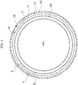
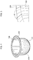
Figure 4 illustrates an example of a shaped sheet of wrapping obtained applying the method described herein; and -
Figure 5 illustrates a detail of the sheet of wrapping ofFigure 4 . - In the ensuing description, various specific details are illustrated, aimed at enabling an in-depth understanding of the embodiments. The embodiments may be provided without one or more of the specific details, or with other methods, components, or materials, etc. In other cases, known structures, materials, or operations are not illustrated or described in detail so that various aspects of the embodiment will not be obscured.
- The references used herein are provided merely for convenience and hence do not define the sphere of protection or the scope of the embodiments.
- As anticipated above, the method described herein regards production of a shaped sheet of wrapping. With reference to
Figure 4 , in particular, the method described herein is suitable for producing a sheet of wrapping 10 having ahollow portion 10A for receiving a product, for example a foodstuff product, and aperimetral edge 10C, which extends along a pre-set profile K. In preferred embodiments, as in the one illustrated, thesheet 10 may comprise a substantially planarperimetral flange 10B, which surrounds thehollow portion 10A and defines theperimetral edge 10C. - With reference to the example of
Figure 1 , the method described herein comprises the steps of: - laying a sheet of wrapping 100 on a
treatment surface 50 having a formingcavity 50A; - forming the sheet of wrapping 100 within the forming
cavity 50A so as to produce thehollow portion 10A; and - cutting the sheet of wrapping 100 along the pre-set profile K so as to produce the
perimetral edge 10C. - Preferably, the sheet of wrapping 100 comprises at least one layer made of metal material, for example aluminium.
- In particular, the sheet of wrapping 100 may be formed by a sheet of aluminium foil coated, on the outer side (with reference to the arrangement in the final package), with a layer of ink, which bestows on the outer surface of the sheet with a pre-set colouring, and/or decoration, and/or image. Possibly, the opposite side, the inner surface (with reference to the arrangement in the final package), may be coated with a layer of heat-sealing material. The sheet of aluminium foil may have a thickness comprised between 1 and 500 µm, possibly between 3 and 300 µm and optionally between 5 and 50 µm (1 µm = 1.10-6 m). Alternatively, the sheet of wrapping 100 may have a multi-layered structure comprising at least one layer of polymeric material. For instance, the sheet of wrapping 100 may be formed by a sheet having a multi-layered laminar structure made up of a plurality of layers of polymeric material. Preferred polymeric materials are, for example, polypropylene, polyethylene, polyester, polyamide, etc. A sheet of plastic material suitable for the application in question may generally have a thickness of less than 140 µm, in particular equal to or less than 50 µm. The
sheet 100 may also comprise heat-sealing material, such as a heat-sealing lacquer. - In some embodiments, the
sheet 100 may present a multi-layered structure comprising at least one layer of polymeric material in combination with a metal layer. For instance, thesheet 100 may consist of a sheet of metallised plastic material (e.g., polypropylene - PP), with a thickness of the metal coating comprised between 10 and 500 Å (1 Å = 1·10-10 m). - In general, in the method described herein, the forming step envisages forming the
sheet 100 substantially without subjecting it to any plastic deformation by stretching. - With reference to
Figures 1A and 1B , the forming step envisages: - laying the sheet of wrapping 100 on the
treatment surface 50 and over the formingcavity 50A; - introducing a forming
member 52 into the formingcavity 50A pushing the sheet of wrapping 100 into thecavity 50A and laying it against thesurface 50A' of the cavity. - At the end of the above step, the
sheet 100 assumes a conformation corresponding to that of thesurface 50A', for the portion thereof that has been inserted into thecavity 50A; this portion identifies thehollow portion 10A. - The forming step can be carried out in cold conditions, i.e., without any application of heat to the sheet of wrapping. Alternatively, the sheet of wrapping may be heated so as to favour deformation thereof into the conformation envisaged for the
hollow portion 10A. - The forming step generates a plurality of folds 110 in the sheet of wrapping 100.
- The folds in question are generated by the fact that the forming step is obtained substantially in the absence of any deformation due stretching the sheet, simply as a result of repositioning thereof from the arrangement where it is laid out flat, illustrated in
Figure 1A , to the arrangement imposed by the formingcavity 50A, illustratedFigure 1B . - The folds 110 are defined by folding lines oriented in a transverse direction with respect to the border in plan view of the
hollow portion 10A, and are each constituted by at least two flaps set on top of one another and in mutual contact, connected together by the respective folding line. - The fold 110 itself is in turn in contact, through one of its two flaps, with an underlying layer of the sheet of wrapping 100. At each fold 110 there may hence be three or more layers of the material laid on top of one another.
- It should moreover be noted that, in certain applications, in particular where the use of a sheet of wrapping made of plastic material is envisaged, the forming operation may be carried out according to the teachings of the patent application No.
PCT WO2018/146577A1 , filed in the name of the present applicant, which envisages sealing the folds referred to above in order to fix the sheet in the conformation assumed within the forming cavity. - As anticipated above, the method described herein envisages a cutting operation that uses a laser beam B for cutting the sheet of wrapping 100 along the pre-set profile K.
- The cutting operation may be performed via a
processing head 60 provided with a laser source of a conventional type, suited for carrying out the functions that will be described hereinafter. The laser source may, for example, be a fibre laser, a YAG laser, or a CO2 laser, and may be either a laser of a pulsed type or a continuous-emission laser. Working parameters of theprocessing head 60, such as the wavelength of the laser beam or else the focal distance, may be selected, according to the common criteria known for laser machining, on the basis of the requirements of the specific applications. - In general, as is known, laser cutting envisages directing the laser beam onto the sheet of wrapping, and orienting it in a continuous way so that its point of incidence on the sheet moves along the given profile envisaged for the edge to be obtained.
- The energy conveyed by the laser beam on the sheet causes, in the point of incidence, a phenomenon of sublimation such that the material involved passes directly from the solid state to the aeriform state.
- According to the method described herein, the cutting operation envisages carrying out a plurality of passes of the laser beam along the pre-set profile K, which comprise:
- a first pass of the laser beam that follows a first path P1; and
- at least one further pass that follows a further path Pn, which is shifted, with respect to the first path P1, in a direction away from the pre-set profile K.
- The further pass or passes of the laser beam has/have the function of eliminating the material of the sheet of wrapping 100 that, at the end of the first pass, still connects the shaped
sheet 10 containing thehollow portion 10A with the residual portion 100' of thesheet 100. - The material mentioned is, in particular, constituted by hidden layers of the sheet that emerge only after the first pass of the laser beam.
- Prevalently, this occurs at the folds 110 referred to above, where there may be, as mentioned, three or more layers of material set on top of one another.
- The first pass of the laser beam will operate on the top layer, whereas the subsequent passes will operate on the underlying layers.
- Each further pass of the laser beam follows a respective path that does not coincide with the path followed in the previous pass, but is slightly shifted therefrom in a direction away from the pre-set profile K.
- Preferably, this displacement amounts to a distance smaller than or equal to the diameter of the laser beam.
- In particular, according to preferred embodiments, the cutting operation includes a number n of further passes of the laser beam, which follow a number n of respective further paths, shifted from the path of the previous pass, away from the pre-set profile K, by respective distances dn corresponding to respective fractions of the diameter of the laser beam. The sum of the distances dn is less than the diameter of the laser beam.
- The number n of passes may, for example, be comprised between 2 and 10. The distances dn may be equal to or less than 50% of the diameter of the laser beam.
- It should be noted that the laser beam operates with working parameters, in particular an operating power, which are such that, in each individual pass, the beam is able to act only on one layer of the sheet.
- In preferred embodiments, the power of the laser beam is less than 500 W.
- With reference now to
Figures 2 and3 , these illustrate an example of operation of cutting of thesheet 100, on which thehollow portion 10A has already been formed, along the pre-set profile K. - The operation illustrated envisages three successive passes of the laser beam along the pre-set profile K that follow respective paths P1, P2, P3, positioned at an ever-increasing distance, starting from the first pass to the third pass, from the pre-set profile K (
Figure 3 ). - The paths P1, P2, P3 represented identify the positions assumed by the centre of the laser beam (with reference to a section of the beam) during movement of the beam along the profile K.
- The path P1 of the first pass extends in such a way that the laser beam is tangential to the pre-set profile K and so remains throughout the path along the profile K.
- The path P2 extends in a direction parallel to the path P1 and is shifted therefrom by a distance d1 equal to half the diameter of the laser beam. This distance is maintained throughout the length of the path along the profile K.
- Likewise, the path P3 extends parallel to the path P2 and is positioned even further away from the path P1. In particular, the path P3 is positioned at a distance d2 from the path P2, which is equal to one quarter of the diameter of the laser beam. This distance is maintained throughout the length of the path. The values of the distances d1 and d2 are provided purely by way of example.
- It may be noted that, since the distances d1 and d2 are less than the diameter of the laser beam, and thus also their sum, the different passes of the laser beam have areas of intersection between the respective areas A1, A2, A3 covered thereby (
Figure 3 ). In particular, a region of intersection A' is identified that is common to all three areas covered by the three passes of the laser beam. - With reference now to
Figure 3 , this shows the action performed by the laser beam during the individual passes, in a region of thesheet 100 present in which is a fold 110 and, as a consequence, threelayers - Once again in
Figure 3 , the hatched boxes appearing on the various layers of the sheet represent portions of these layers that are progressively eliminated following upon the various passes of the laser beam. - As represented in
Figure 3 , the first pass along the path P1 causes elimination of the portion 101I of thefirst layer 101. - The second pass along the path P2 in turn causes elimination of the
portion 1021 of thesecond layer 102, in the area of intersection between the area A1 covered in the first pass and the area A2 covered in the second pass, and moreover elimination of the portion 101II of thefirst layer 101 in the remaining region of the area A2 covered by the second pass. - Finally, the third pass along the path P3 brings about:
- elimination of the
portion 1031 of thethird layer 103 in the region of intersection A' common to the three areas A1, A2, and A3 covered by the three passes of the laser beam; - elimination of the portion 102II of the
second layer 102 in the region of intersection between the area A2 covered by the second pass and the area A1 covered by the first pass; and - elimination of the portion 101III of the
first layer 101 for the remaining region of the area covered by the third pass. - In the region A', the material of all three
layers sheet 100 has hence been obtained. In the example illustrated, each pass of the laser beam eliminates exactly one layer of the sheet. This choice has been made to facilitate understanding of the solution. It will be clear to the person skilled in the sector that the individual passes may also eliminate just a part of a single layer of the sheet or else eliminate an entire layer plus a part of the underlying layer, according to the requirements of the individual applications. In any case, complete cutting of the sheet is obtained only after execution of multiple passes of the laser beam, in the way described above. - In view of the foregoing, it should now be noted that the present applicant has been able to verify that execution of laser cutting of the sheet of wrapping in the way referred to makes it possible to guarantee complete cutting of the sheet and at the same time preserve the surface characteristics of the sheet also along the
edge 10C that is obtained from the cutting operation. - This can be attributed to the fact that the laser beam is made to operate at a contained power, as a result of which the multiple passes referred to above are necessary, as well as to the fact that these passes are not performed along one and the same path, but along distinct paths.
- For the reasons referred to above, the method described herein proves particularly advantageous for applications with printed sheets of wrapping (i.e., sheets coated with a layer of ink) in so far as it becomes possible to preserve the printing layer also along the perimetral edge of the sheet, obtained from cutting, thus considerably enhancing the quality of the final package.
- In applications in which the sheet of wrapping 100 has, in combination, a layer of polymeric material and a layer of metal material, the cutting step may envisage the use of two laser beams, characterised by different wavelengths, one for treatment of the layer of polymeric material and the other for treatment of the metal layer. For instance, it is possible to use a CO2 laser source for treatment of the layer of polymeric material, and a fibre laser or a YAG laser for treatment of the metal layer.
- Preferred modes of use of the two laser beams are described in the patent application No.
EP 3523084A1 , filed in the name of the present applicant. - Of course, without prejudice to the principle of the invention, the details of construction and the embodiments may vary, even significantly, with respect to what has been illustrated herein purely by way of non-limiting example, without thereby departing from the scope of the invention, as defined by the annexed claims.
Claims (12)
- A method for producing a shaped sheet of wrapping (10), comprising a hollow portion (10A) and a perimetral edge (10C) that extends along a pre-set profile (K), said method comprising the steps of:- laying a sheet of wrapping (100) on a treatment surface (50) having a forming cavity (50A); and- forming said sheet of wrapping (100) within said forming cavity (50A) so as to reproduce the shape of said hollow portion (10A) thereon,
wherein said forming step includes inserting said sheet of wrapping (100) into said forming cavity (50A), without subjecting it to deformation by stretching at least for a phase of said action of insertion, said formed sheet (100) having a plurality of folds (110) consisting of two or more layers set on top of and in contact with one another of said sheet of wrapping (100);- cutting said formed sheet of wrapping (100) along said pre-set profile (K) for producing said perimetral edge (10C) and obtaining said shaped sheet of wrapping (10);
said method being characterised in that said cutting step comprises the use of a laser source (60) designed to emit a laser beam (B), and includes applying said laser beam (B) on said formed sheet (100) and orienting said laser beam so as to carry out a plurality of passes of said laser beam along said pre-set profile (K), wherein said plurality of passes comprises:- a first pass of said laser beam that follows a first path (P1); and- at least one further pass of said laser beam that follows a further path (P2, P3, ..., Pn) that is shifted from said first path (P1), in a direction away from said pre-set profile (K), by a given distance (d1, d2) such that the laser beam that follows said further path (P2, P3, ..., Pn) can operate on an underlying layer of the formed sheet (100) that still connects said shaped sheet (10) to a residual portion (100') of said sheet of wrapping (100) and that emerges on the side where the laser source is located as a result of said first pass of said laser beam. - The method according to Claim 1, wherein said distance (d1, d2) is smaller than or equal to the diameter of said laser beam.
- The method according to 1 or Claim 2, wherein said at least one further pass includes a number n of passes that follow a number n of respective paths (P2, P3, ..., Pn) shifted with respect to the path of the previous pass, in a direction away from said pre-set profile (K), by respective distances (d1, d2, dn) corresponding to respective fractions of the diameter of said laser beam, where the sum of said distances (d1, d2, dn) of said n further passes is less than the diameter of said laser beam.
- The method according to any one of the preceding claims, wherein inserting said sheet into said forming cavity includes:- providing a forming member (52), which is to cooperate with said forming cavity (50A);- laying said sheet of wrapping (100) on said treatment surface (50) and over said forming cavity (50A); and- bringing said forming member (52) into said forming cavity (50A), pushing said sheet of wrapping (100) into said cavity (50A) by means of said member (52) .
- The method according to any one of the preceding claims, wherein said shaped sheet (10) comprises a peripheral flange (10B) that extends around said hollow portion (10A) and defines said perimetral edge (10C), wherein said cutting step includes orienting said laser beam along a pre-set profile (K) that is located at a given distance from said hollow portion (10A) so as to produce said peripheral flange (10B).
- The method according to any one of the preceding claims, wherein said sheet of wrapping (100) comprises at least one layer of metal material, preferably a sheet of aluminium.
- The method according to Claim 6, wherein one side of said sheet is coated with a layer of ink.
- The method according to Claim 7, wherein the opposite side of said sheet is coated with a layer of heat-sealing material.
- The method according to any one of the preceding claims, wherein said sheet of wrapping (100) has a multi-layered structure comprising at least one layer of polymeric material.
- The method according to Claim 9, wherein said sheet of wrapping comprises a heat-sealing layer, for example a heat-sealing lacquer.
- The method according to Claim 9 or Claim 10, wherein said sheet of wrapping (100) has a multi-layered structure comprising a layer of polymeric material in combination with a metal layer.
- The method according to Claim 11, wherein said cutting step envisages applying said laser beam on said metal layer, and applying a further laser beam, of different wavelength, on said layer of polymeric material.
Applications Claiming Priority (1)
| Application Number | Priority Date | Filing Date | Title |
|---|---|---|---|
| LU101585A LU101585B1 (en) | 2019-12-30 | 2019-12-30 | Method for producing a shaped sheet of wrapping |
Publications (2)
| Publication Number | Publication Date |
|---|---|
| EP3845362A1 EP3845362A1 (en) | 2021-07-07 |
| EP3845362B1 true EP3845362B1 (en) | 2022-08-10 |
Family
ID=69158289
Family Applications (1)
| Application Number | Title | Priority Date | Filing Date |
|---|---|---|---|
| EP20209607.9A Active EP3845362B1 (en) | 2019-12-30 | 2020-11-24 | Method for producing a shaped sheet of wrapping |
Country Status (6)
| Country | Link |
|---|---|
| US (1) | US11806811B2 (en) |
| EP (1) | EP3845362B1 (en) |
| CN (1) | CN113059275B (en) |
| CA (1) | CA3100375A1 (en) |
| LU (1) | LU101585B1 (en) |
| PL (1) | PL3845362T3 (en) |
Families Citing this family (5)
| Publication number | Priority date | Publication date | Assignee | Title |
|---|---|---|---|---|
| KR102819808B1 (en) * | 2020-06-15 | 2025-06-16 | 삼성디스플레이 주식회사 | Window molding apparatus and window molding method using the same |
| DE102021202964A1 (en) * | 2021-03-25 | 2022-09-29 | Fraunhofer-Gesellschaft zur Förderung der angewandten Forschung eingetragener Verein | Method and apparatus for cutting metal-containing foil and laser-cut metal-containing foil |
| CN114801320B (en) * | 2022-05-16 | 2023-05-26 | 山东大学 | Paperboard stamping forming device and method |
| CN117245595A (en) * | 2023-09-22 | 2023-12-19 | 中国原子能科学研究院 | Assembly method and assembly device |
| DE102024101845A1 (en) * | 2024-01-23 | 2025-07-24 | Fire-Flow Vertriebs- und Marketing GmbH | Method for manufacturing an ashtray |
Family Cites Families (13)
| Publication number | Priority date | Publication date | Assignee | Title |
|---|---|---|---|---|
| NL6408387A (en) * | 1963-07-26 | 1965-01-27 | ||
| NL8500720A (en) * | 1984-05-22 | 1985-07-01 | Highland Supply Corp | SYSTEM FOR FORMING ARTICLES. |
| US5479761A (en) * | 1988-09-26 | 1996-01-02 | Highland Supply Corporation | Method of wrapping a food item |
| US6255621B1 (en) * | 2000-01-31 | 2001-07-03 | International Business Machines Corporation | Laser cutting method for forming magnetic recording head sliders |
| NL1025282C2 (en) * | 2004-01-19 | 2005-07-20 | Shieltronics B V | Method for producing container parts, container parts, method for producing a multi-layer film, multi-layer film. |
| BE1016464A3 (en) * | 2005-02-23 | 2006-11-07 | Flooring Ind Ltd | Manufacture of laminate floor panels used in forming floating floor covering, involves forming floor panels at least partially using laser treatment of board-shaped material |
| US20080052173A1 (en) * | 2006-08-28 | 2008-02-28 | Mei-Lin Liou | Fast food wrapping and delivery system and method for the same |
| US10470486B2 (en) * | 2013-10-04 | 2019-11-12 | Culpitt Ii, Llc | Laser cut edible decorating sheet and methods of manufacture |
| BR112016026388B1 (en) * | 2014-05-19 | 2021-10-13 | Soremartec S.A | PROCESS TO PRODUCE A PACKAGING, PACKAGING FOR A FOOD PRODUCT, DEVICE TO IMPLEMENT A SEALING STAGE IN A PROCESS AND PACKAGED FOOD PRODUCT |
| LU93248B1 (en) | 2016-10-04 | 2018-04-05 | Soremartec Sa | Laser treatment of wrapping materials |
| LU100074B1 (en) * | 2017-02-09 | 2018-10-02 | Soremartec Sa | Process for hot forming of a sheet of wrapping made of plastic material |
| US11524916B2 (en) * | 2017-11-30 | 2022-12-13 | Saint-Gobain Glass France | Method for producing a printed, coated panel |
| US11548099B2 (en) * | 2018-12-03 | 2023-01-10 | Mitsubishi Electric Corporation | Laser processing method and laser processing apparatus |
-
2019
- 2019-12-30 LU LU101585A patent/LU101585B1/en active IP Right Grant
-
2020
- 2020-11-23 CA CA3100375A patent/CA3100375A1/en active Pending
- 2020-11-24 EP EP20209607.9A patent/EP3845362B1/en active Active
- 2020-11-24 PL PL20209607.9T patent/PL3845362T3/en unknown
- 2020-12-08 US US17/115,172 patent/US11806811B2/en active Active
- 2020-12-23 CN CN202011542864.8A patent/CN113059275B/en active Active
Also Published As
| Publication number | Publication date |
|---|---|
| US11806811B2 (en) | 2023-11-07 |
| LU101585B1 (en) | 2021-06-30 |
| US20210197321A1 (en) | 2021-07-01 |
| PL3845362T3 (en) | 2023-02-06 |
| CN113059275A (en) | 2021-07-02 |
| CN113059275B (en) | 2024-03-19 |
| CA3100375A1 (en) | 2021-06-30 |
| EP3845362A1 (en) | 2021-07-07 |
Similar Documents
| Publication | Publication Date | Title |
|---|---|---|
| EP3845362B1 (en) | Method for producing a shaped sheet of wrapping | |
| US9782927B2 (en) | Method and device for joining transfer or laminating film webs | |
| EP0185897B1 (en) | Method for the treatment of packing material and the material treated accordingly | |
| CN1189333C (en) | embossed sheet | |
| US20090166562A1 (en) | Production of microfluidic devices using laser-induced shockwaves | |
| US20110150371A1 (en) | Flexible Pouch With Easy-Opening Features | |
| EP2024172B1 (en) | A method for protecting the untrimmed edge of a paperboard or paper | |
| EP1324929B1 (en) | A packaging laminate for a retortable packaging carton | |
| US10173369B2 (en) | Multi-layer product with sealing areas of varying temperature | |
| US20020123418A1 (en) | Laser system for making creases in cardboard | |
| RU2805853C2 (en) | Method for manufacturing moulded wrapper sheet | |
| JP2002127684A (en) | Method and device for manufacturing cylindrical embossed sheet | |
| US5863370A (en) | Method of bonding cloth cover to substrate base | |
| KR20190041133A (en) | Method for manufacturing three dimensional shapes using laser and powder | |
| KR100222582B1 (en) | Laser welder with 2 head and the method of using it | |
| WO2004026522A1 (en) | Method for laser working a film material and film material to be worked using that method. | |
| EP3774162A1 (en) | Apparatus and method for processing cardboard | |
| RU2000113738A (en) | METHOD FOR MANUFACTURING PRODUCTS SYMMETRIC WITH RESPECT TO THE ROTATION AXIS, FROM SHEET METAL WITH DOUBLE CURVITY SURFACE AND VARIABLE MATERIAL THICKNESS | |
| EP4308336A1 (en) | Method for processing a cardboard with a laser beam | |
| FI68784C (en) | FOERFARANDE FOER FRAMSTAELLNING AV EN JAEMN LAMINERAD PRODUKT MEDELST EXTRUDERING | |
| KR20190023456A (en) | Laser welding method for plating steel sheet | |
| CA2770072A1 (en) | Flexible pouch with easy opening features |
Legal Events
| Date | Code | Title | Description |
|---|---|---|---|
| PUAI | Public reference made under article 153(3) epc to a published international application that has entered the european phase |
Free format text: ORIGINAL CODE: 0009012 |
|
| STAA | Information on the status of an ep patent application or granted ep patent |
Free format text: STATUS: THE APPLICATION HAS BEEN PUBLISHED |
|
| AK | Designated contracting states |
Kind code of ref document: A1 Designated state(s): AL AT BE BG CH CY CZ DE DK EE ES FI FR GB GR HR HU IE IS IT LI LT LU LV MC MK MT NL NO PL PT RO RS SE SI SK SM TR |
|
| STAA | Information on the status of an ep patent application or granted ep patent |
Free format text: STATUS: REQUEST FOR EXAMINATION WAS MADE |
|
| 17P | Request for examination filed |
Effective date: 20211213 |
|
| RBV | Designated contracting states (corrected) |
Designated state(s): AL AT BE BG CH CY CZ DE DK EE ES FI FR GB GR HR HU IE IS IT LI LT LU LV MC MK MT NL NO PL PT RO RS SE SI SK SM TR |
|
| GRAP | Despatch of communication of intention to grant a patent |
Free format text: ORIGINAL CODE: EPIDOSNIGR1 |
|
| STAA | Information on the status of an ep patent application or granted ep patent |
Free format text: STATUS: GRANT OF PATENT IS INTENDED |
|
| RIC1 | Information provided on ipc code assigned before grant |
Ipc: B23K 101/04 20060101ALN20220322BHEP Ipc: B31B 50/44 20170101ALN20220322BHEP Ipc: B23K 103/10 20060101ALN20220322BHEP Ipc: B31B 160/20 20170101ALN20220322BHEP Ipc: B23K 101/10 20060101ALN20220322BHEP Ipc: B23K 101/34 20060101ALN20220322BHEP Ipc: B23K 101/18 20060101ALN20220322BHEP Ipc: B23K 26/40 20140101ALN20220322BHEP Ipc: B23K 26/0622 20140101ALN20220322BHEP Ipc: B21D 22/20 20060101ALN20220322BHEP Ipc: B29K 705/02 20060101ALN20220322BHEP Ipc: B29K 705/00 20060101ALN20220322BHEP Ipc: B29C 43/40 20060101ALN20220322BHEP Ipc: B29C 43/18 20060101ALI20220322BHEP Ipc: B21D 24/16 20060101ALI20220322BHEP Ipc: B21D 22/21 20060101ALI20220322BHEP Ipc: B23K 26/38 20140101ALI20220322BHEP Ipc: B31B 70/16 20170101ALI20220322BHEP Ipc: B29C 43/20 20060101ALI20220322BHEP Ipc: B65B 51/22 20060101ALI20220322BHEP Ipc: B65B 47/06 20060101ALI20220322BHEP Ipc: B65B 11/52 20060101ALI20220322BHEP Ipc: B31F 1/00 20060101ALI20220322BHEP Ipc: B29C 51/26 20060101ALI20220322BHEP Ipc: B29C 51/14 20060101ALI20220322BHEP Ipc: B29C 51/08 20060101ALI20220322BHEP Ipc: B29C 51/00 20060101AFI20220322BHEP |
|
| INTG | Intention to grant announced |
Effective date: 20220406 |
|
| GRAS | Grant fee paid |
Free format text: ORIGINAL CODE: EPIDOSNIGR3 |
|
| GRAA | (expected) grant |
Free format text: ORIGINAL CODE: 0009210 |
|
| STAA | Information on the status of an ep patent application or granted ep patent |
Free format text: STATUS: THE PATENT HAS BEEN GRANTED |
|
| AK | Designated contracting states |
Kind code of ref document: B1 Designated state(s): AL AT BE BG CH CY CZ DE DK EE ES FI FR GB GR HR HU IE IS IT LI LT LU LV MC MK MT NL NO PL PT RO RS SE SI SK SM TR |
|
| REG | Reference to a national code |
Ref country code: AT Ref legal event code: REF Ref document number: 1510192 Country of ref document: AT Kind code of ref document: T Effective date: 20220815 Ref country code: CH Ref legal event code: EP |
|
| REG | Reference to a national code |
Ref country code: IE Ref legal event code: FG4D |
|
| REG | Reference to a national code |
Ref country code: DE Ref legal event code: R096 Ref document number: 602020004463 Country of ref document: DE |
|
| REG | Reference to a national code |
Ref country code: NL Ref legal event code: MP Effective date: 20220810 |
|
| REG | Reference to a national code |
Ref country code: LT Ref legal event code: MG9D |
|
| PG25 | Lapsed in a contracting state [announced via postgrant information from national office to epo] |
Ref country code: SE Free format text: LAPSE BECAUSE OF FAILURE TO SUBMIT A TRANSLATION OF THE DESCRIPTION OR TO PAY THE FEE WITHIN THE PRESCRIBED TIME-LIMIT Effective date: 20220810 Ref country code: RS Free format text: LAPSE BECAUSE OF FAILURE TO SUBMIT A TRANSLATION OF THE DESCRIPTION OR TO PAY THE FEE WITHIN THE PRESCRIBED TIME-LIMIT Effective date: 20220810 Ref country code: PT Free format text: LAPSE BECAUSE OF FAILURE TO SUBMIT A TRANSLATION OF THE DESCRIPTION OR TO PAY THE FEE WITHIN THE PRESCRIBED TIME-LIMIT Effective date: 20221212 Ref country code: NO Free format text: LAPSE BECAUSE OF FAILURE TO SUBMIT A TRANSLATION OF THE DESCRIPTION OR TO PAY THE FEE WITHIN THE PRESCRIBED TIME-LIMIT Effective date: 20221110 Ref country code: NL Free format text: LAPSE BECAUSE OF FAILURE TO SUBMIT A TRANSLATION OF THE DESCRIPTION OR TO PAY THE FEE WITHIN THE PRESCRIBED TIME-LIMIT Effective date: 20220810 Ref country code: LV Free format text: LAPSE BECAUSE OF FAILURE TO SUBMIT A TRANSLATION OF THE DESCRIPTION OR TO PAY THE FEE WITHIN THE PRESCRIBED TIME-LIMIT Effective date: 20220810 Ref country code: LT Free format text: LAPSE BECAUSE OF FAILURE TO SUBMIT A TRANSLATION OF THE DESCRIPTION OR TO PAY THE FEE WITHIN THE PRESCRIBED TIME-LIMIT Effective date: 20220810 Ref country code: FI Free format text: LAPSE BECAUSE OF FAILURE TO SUBMIT A TRANSLATION OF THE DESCRIPTION OR TO PAY THE FEE WITHIN THE PRESCRIBED TIME-LIMIT Effective date: 20220810 |
|
| REG | Reference to a national code |
Ref country code: AT Ref legal event code: MK05 Ref document number: 1510192 Country of ref document: AT Kind code of ref document: T Effective date: 20220810 |
|
| PG25 | Lapsed in a contracting state [announced via postgrant information from national office to epo] |
Ref country code: IS Free format text: LAPSE BECAUSE OF FAILURE TO SUBMIT A TRANSLATION OF THE DESCRIPTION OR TO PAY THE FEE WITHIN THE PRESCRIBED TIME-LIMIT Effective date: 20221210 Ref country code: HR Free format text: LAPSE BECAUSE OF FAILURE TO SUBMIT A TRANSLATION OF THE DESCRIPTION OR TO PAY THE FEE WITHIN THE PRESCRIBED TIME-LIMIT Effective date: 20220810 Ref country code: GR Free format text: LAPSE BECAUSE OF FAILURE TO SUBMIT A TRANSLATION OF THE DESCRIPTION OR TO PAY THE FEE WITHIN THE PRESCRIBED TIME-LIMIT Effective date: 20221111 |
|
| PG25 | Lapsed in a contracting state [announced via postgrant information from national office to epo] |
Ref country code: SM Free format text: LAPSE BECAUSE OF FAILURE TO SUBMIT A TRANSLATION OF THE DESCRIPTION OR TO PAY THE FEE WITHIN THE PRESCRIBED TIME-LIMIT Effective date: 20220810 Ref country code: RO Free format text: LAPSE BECAUSE OF FAILURE TO SUBMIT A TRANSLATION OF THE DESCRIPTION OR TO PAY THE FEE WITHIN THE PRESCRIBED TIME-LIMIT Effective date: 20220810 Ref country code: ES Free format text: LAPSE BECAUSE OF FAILURE TO SUBMIT A TRANSLATION OF THE DESCRIPTION OR TO PAY THE FEE WITHIN THE PRESCRIBED TIME-LIMIT Effective date: 20220810 Ref country code: DK Free format text: LAPSE BECAUSE OF FAILURE TO SUBMIT A TRANSLATION OF THE DESCRIPTION OR TO PAY THE FEE WITHIN THE PRESCRIBED TIME-LIMIT Effective date: 20220810 Ref country code: CZ Free format text: LAPSE BECAUSE OF FAILURE TO SUBMIT A TRANSLATION OF THE DESCRIPTION OR TO PAY THE FEE WITHIN THE PRESCRIBED TIME-LIMIT Effective date: 20220810 Ref country code: AT Free format text: LAPSE BECAUSE OF FAILURE TO SUBMIT A TRANSLATION OF THE DESCRIPTION OR TO PAY THE FEE WITHIN THE PRESCRIBED TIME-LIMIT Effective date: 20220810 |
|
| REG | Reference to a national code |
Ref country code: DE Ref legal event code: R097 Ref document number: 602020004463 Country of ref document: DE |
|
| PG25 | Lapsed in a contracting state [announced via postgrant information from national office to epo] |
Ref country code: SK Free format text: LAPSE BECAUSE OF FAILURE TO SUBMIT A TRANSLATION OF THE DESCRIPTION OR TO PAY THE FEE WITHIN THE PRESCRIBED TIME-LIMIT Effective date: 20220810 Ref country code: EE Free format text: LAPSE BECAUSE OF FAILURE TO SUBMIT A TRANSLATION OF THE DESCRIPTION OR TO PAY THE FEE WITHIN THE PRESCRIBED TIME-LIMIT Effective date: 20220810 |
|
| PLBE | No opposition filed within time limit |
Free format text: ORIGINAL CODE: 0009261 |
|
| STAA | Information on the status of an ep patent application or granted ep patent |
Free format text: STATUS: NO OPPOSITION FILED WITHIN TIME LIMIT |
|
| PG25 | Lapsed in a contracting state [announced via postgrant information from national office to epo] |
Ref country code: MC Free format text: LAPSE BECAUSE OF FAILURE TO SUBMIT A TRANSLATION OF THE DESCRIPTION OR TO PAY THE FEE WITHIN THE PRESCRIBED TIME-LIMIT Effective date: 20220810 Ref country code: AL Free format text: LAPSE BECAUSE OF FAILURE TO SUBMIT A TRANSLATION OF THE DESCRIPTION OR TO PAY THE FEE WITHIN THE PRESCRIBED TIME-LIMIT Effective date: 20220810 |
|
| P01 | Opt-out of the competence of the unified patent court (upc) registered |
Effective date: 20230529 |
|
| 26N | No opposition filed |
Effective date: 20230511 |
|
| PG25 | Lapsed in a contracting state [announced via postgrant information from national office to epo] |
Ref country code: SI Free format text: LAPSE BECAUSE OF FAILURE TO SUBMIT A TRANSLATION OF THE DESCRIPTION OR TO PAY THE FEE WITHIN THE PRESCRIBED TIME-LIMIT Effective date: 20220810 Ref country code: LU Free format text: LAPSE BECAUSE OF NON-PAYMENT OF DUE FEES Effective date: 20221124 |
|
| PG25 | Lapsed in a contracting state [announced via postgrant information from national office to epo] |
Ref country code: IE Free format text: LAPSE BECAUSE OF NON-PAYMENT OF DUE FEES Effective date: 20221124 |
|
| PG25 | Lapsed in a contracting state [announced via postgrant information from national office to epo] |
Ref country code: CY Free format text: LAPSE BECAUSE OF FAILURE TO SUBMIT A TRANSLATION OF THE DESCRIPTION OR TO PAY THE FEE WITHIN THE PRESCRIBED TIME-LIMIT Effective date: 20220810 |
|
| PG25 | Lapsed in a contracting state [announced via postgrant information from national office to epo] |
Ref country code: MK Free format text: LAPSE BECAUSE OF FAILURE TO SUBMIT A TRANSLATION OF THE DESCRIPTION OR TO PAY THE FEE WITHIN THE PRESCRIBED TIME-LIMIT Effective date: 20220810 |
|
| PG25 | Lapsed in a contracting state [announced via postgrant information from national office to epo] |
Ref country code: TR Free format text: LAPSE BECAUSE OF FAILURE TO SUBMIT A TRANSLATION OF THE DESCRIPTION OR TO PAY THE FEE WITHIN THE PRESCRIBED TIME-LIMIT Effective date: 20220810 |
|
| REG | Reference to a national code |
Ref country code: CH Ref legal event code: PL |
|
| PG25 | Lapsed in a contracting state [announced via postgrant information from national office to epo] |
Ref country code: CH Free format text: LAPSE BECAUSE OF NON-PAYMENT OF DUE FEES Effective date: 20231130 |
|
| PG25 | Lapsed in a contracting state [announced via postgrant information from national office to epo] |
Ref country code: CH Free format text: LAPSE BECAUSE OF NON-PAYMENT OF DUE FEES Effective date: 20231130 Ref country code: BG Free format text: LAPSE BECAUSE OF FAILURE TO SUBMIT A TRANSLATION OF THE DESCRIPTION OR TO PAY THE FEE WITHIN THE PRESCRIBED TIME-LIMIT Effective date: 20220810 |
|
| PG25 | Lapsed in a contracting state [announced via postgrant information from national office to epo] |
Ref country code: MT Free format text: LAPSE BECAUSE OF FAILURE TO SUBMIT A TRANSLATION OF THE DESCRIPTION OR TO PAY THE FEE WITHIN THE PRESCRIBED TIME-LIMIT Effective date: 20220810 |
|
| GBPC | Gb: european patent ceased through non-payment of renewal fee |
Effective date: 20241124 |
|
| PG25 | Lapsed in a contracting state [announced via postgrant information from national office to epo] |
Ref country code: HU Free format text: LAPSE BECAUSE OF FAILURE TO SUBMIT A TRANSLATION OF THE DESCRIPTION OR TO PAY THE FEE WITHIN THE PRESCRIBED TIME-LIMIT; INVALID AB INITIO Effective date: 20201124 |
|
| PG25 | Lapsed in a contracting state [announced via postgrant information from national office to epo] |
Ref country code: GB Free format text: LAPSE BECAUSE OF NON-PAYMENT OF DUE FEES Effective date: 20241124 |
|
| PGFP | Annual fee paid to national office [announced via postgrant information from national office to epo] |
Ref country code: DE Payment date: 20251022 Year of fee payment: 6 |
|
| PGFP | Annual fee paid to national office [announced via postgrant information from national office to epo] |
Ref country code: IT Payment date: 20251022 Year of fee payment: 6 |
|
| PGFP | Annual fee paid to national office [announced via postgrant information from national office to epo] |
Ref country code: FR Payment date: 20251022 Year of fee payment: 6 |
|
| PGFP | Annual fee paid to national office [announced via postgrant information from national office to epo] |
Ref country code: BE Payment date: 20251022 Year of fee payment: 6 |
|
| PGFP | Annual fee paid to national office [announced via postgrant information from national office to epo] |
Ref country code: PL Payment date: 20251105 Year of fee payment: 6 |