EP3845348A1 - Bolt cutter - Google Patents
Bolt cutter Download PDFInfo
- Publication number
- EP3845348A1 EP3845348A1 EP21158758.9A EP21158758A EP3845348A1 EP 3845348 A1 EP3845348 A1 EP 3845348A1 EP 21158758 A EP21158758 A EP 21158758A EP 3845348 A1 EP3845348 A1 EP 3845348A1
- Authority
- EP
- European Patent Office
- Prior art keywords
- bore
- plunger
- handle
- cutting head
- adjustable
- Prior art date
- Legal status (The legal status is an assumption and is not a legal conclusion. Google has not performed a legal analysis and makes no representation as to the accuracy of the status listed.)
- Granted
Links
Images



Classifications
-
- B—PERFORMING OPERATIONS; TRANSPORTING
- B26—HAND CUTTING TOOLS; CUTTING; SEVERING
- B26B—HAND-HELD CUTTING TOOLS NOT OTHERWISE PROVIDED FOR
- B26B17/00—Hand cutting tools, i.e. with the cutting action actuated by muscle power with two jaws which come into abutting contact
- B26B17/02—Hand cutting tools, i.e. with the cutting action actuated by muscle power with two jaws which come into abutting contact with jaws operated indirectly by the handles, e.g. through cams or toggle levers
-
- B—PERFORMING OPERATIONS; TRANSPORTING
- B25—HAND TOOLS; PORTABLE POWER-DRIVEN TOOLS; MANIPULATORS
- B25G—HANDLES FOR HAND IMPLEMENTS
- B25G1/00—Handle constructions
- B25G1/04—Handle constructions telescopic; extensible; sectional
-
- B—PERFORMING OPERATIONS; TRANSPORTING
- B25—HAND TOOLS; PORTABLE POWER-DRIVEN TOOLS; MANIPULATORS
- B25G—HANDLES FOR HAND IMPLEMENTS
- B25G1/00—Handle constructions
- B25G1/04—Handle constructions telescopic; extensible; sectional
- B25G1/043—Handle constructions telescopic; extensible; sectional for screwdrivers, wrenches or spanners
-
- B—PERFORMING OPERATIONS; TRANSPORTING
- B25—HAND TOOLS; PORTABLE POWER-DRIVEN TOOLS; MANIPULATORS
- B25G—HANDLES FOR HAND IMPLEMENTS
- B25G1/00—Handle constructions
- B25G1/06—Handle constructions reversible or adjustable for position
-
- B—PERFORMING OPERATIONS; TRANSPORTING
- B25—HAND TOOLS; PORTABLE POWER-DRIVEN TOOLS; MANIPULATORS
- B25G—HANDLES FOR HAND IMPLEMENTS
- B25G1/00—Handle constructions
- B25G1/06—Handle constructions reversible or adjustable for position
- B25G1/063—Handle constructions reversible or adjustable for position for screwdrivers, wrenches or spanners
- B25G1/066—Handle constructions reversible or adjustable for position for screwdrivers, wrenches or spanners the grip itself being angularly adjustable
Definitions
- the present invention relates to a cutter, and more specifically to an adjustable bolt cutters.
- the invention provides, in one aspect, a cutter including a cutting head and an adjustable handle pivotally coupled to the cutting head.
- the adjustable handle includes a first adjustment mechanism to change a length the adjustable handle extends from the cutting head.
- the adjustable handle further includes a second adjustment mechanism to change the position of the adjustable handle with respect to the cutting head.
- the invention provides, in another aspect, a cutter including a cutting head with a first bore and an adjustable handle pivotally coupled to the cutting head.
- the adjustable handle includes a second bore and an angle adjustment assembly to change the position of the adjustable handle with respect to the first bore.
- the first bore and the second bore define an axis about which the adjustable handle pivots with respect to the cutting head.
- the angle adjustment assembly includes a plunger received within the first bore and the second bore. The plunger is movable between a locked position in which the adjustable handle is fixed with respect to the first bore and an unlocked position in which the adjustable handle is movable with respect to the first bore.
- the invention provides, in another aspect, a cutter comprising a cutting head and a first handle coupled to the cutting head.
- the first handle extends a first length from the cutting head and extends from a central axis at a first angle.
- the cutter also includes a second handle coupled to the cutting head.
- the second handle extends a second length from the cutting head, and the second length is larger than the first length.
- the second handle also extends from the central axis at a second angle, and the second angle is larger than the first angle.
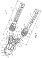
- a bolt cutter 10 is illustrated including a cutting head 14, a first adjustable handle 18, and a second adjustable handle 22.
- the cutting head 14 includes a first cutting blade 26 and a second cutting blade 30 coupled together by plates 34 and corresponding fasteners 38.
- the first cutting blade 26 and the second cutting blade 30 are pivotable about a pin 42 ( FIG. 6 ) that is sandwiched between the plates 34.
- the pin 42 allows the first and second cutting blades 26, 30 to move with respect to each other about an axis 46 ( FIG. 6 ) defined by the pin 42.
- the first and second cutting blades 26, 30 are movable between an open position (i.e., with the cutting portions of the blades 26, 30 spaced apart; FIG.
- the cutting head 14 further includes a compound hinge 50 to increase the cutting force of the blades 26, 30 resulting from the force exerted by a user on the adjustable handles 18, 22.
- the compound hinge 50 includes a first link 54 coupled to the first cutting blade 26 and a second link 58 coupled to the second cutting blade 30.
- the first link 54 is pivotally coupled to the first cutting blade 26 about a pivot axis 62 defined by a fastener 66
- the second link 58 is pivotally coupled to the second cutting blade 30 about a pivot axis 70 defined by a fastener 74.
- the first link 54 and the second link 58 are also pivotally coupled to each other about a pivot axis 78 defined by a fastener 82.
- the first adjustable handle 18 is pivotally coupled to the first link 54 about a pivot axis 86 and the second adjustable handle 22 is pivotally coupled to the second link 58 about a pivot axis 90.
- the first and second adjustable handles 18, 22 each include a length adjustment assembly 94 (i.e., a first adjustment assembly) to allow a user to change the length the adjustable handles 18, 22 extend from the cutting head 14.
- the first and second adjustable handles 18, 22 each include a first handle member 98 and a second handle member 102 that telescopically receives the first handle member 98 within a bore 106 formed in the second handle member 102 ( FIG. 3 ).
- the second handle member 102 also includes a grip portion 110, formed by, for example, an over-molding process.
- the length adjustment assembly 94 couples the first handle member 98 to the second handle member 102.
- the length adjustment assembly 94 is movable between a locked position ( FIGS. 3-4 ) in which the first handle member 98 is fixed relative to the second handle member 102, and an unlocked position (i.e., a released position) (not shown) in which the first handle member 98 is movable with respect to the second handle member 102.
- the length adjustment assembly 94 includes a spring 114 (i.e., a biasing member) to bias the length adjustment assembly 94 toward the locked position.
- the spring 114 is a torsional spring.
- the length adjustment assembly includes a rotatable collar 118 (i.e., a movable lock) with two radially inwardly extending protrusions 122.
- the protrusions 122 are spaced approximately 180 degrees apart.
- a slot 126 is formed on a first side of the first handle member 94, and a similar slot 126 is formed on an opposite, second side of the first handle member 94.
- the protrusions 122 are received within the corresponding slots 126.
- Each of the slots 126 includes three grooves 130A, 130B, 130C to receive the protrusion 122 when the length adjustment assembly 94 is in the locked position.
- each of the grooves 130A, 130B, 130C corresponds to a different length the adjustable handle 94 extends from the cutting head 14.
- the spring 114 biases the collar 118 to rotate in order to urge the protrusions 122 into one of the grooves 130A-130C formed in the telescoping first handle member 98.
- the first handle member 98 is locked with respect to the second handle member 102.
- the rotatable collar 118 is mounted for rotation about the second handle member 102.
- the rotatable collar 118 is mounted for rotation about the first handle member 98 and the slot 126 is formed on the second handle member 102.
- the second handle member 102 may be telescopically received within the first handle member 98.
- the protrusions 122 are formed as part of a removable cover 134 that is secured to the rotatable collar 118 by a fastener 138.
- the removable cover 134 includes indicia indicating which direction the user needs to rotate the collar 118 in order to unlock the length adjustment assembly 94.
- a fastener 142 ( FIG. 4 ) is secured to the second handle member 102 and is received within the slot 126 in order to prevent the first handle member 98 from being completely removed from the bore 106 of the second handle member 102.
- the adjustable handles 18, 22 define a length 146, 150, respectively, that the handles 18, 22 extend from the cutting head 14.
- the length adjustment assembly 94 selectively locks and unlocks the telescoping first handle members 98 in order to adjust the lengths 146, 150.
- the protrusions 122 are received within the first grooves 130A to secure the adjustable handles 18, 22 with a first length 146A, 150A ( FIG.
- the protrusions 122 are received within the third grooves 130C to secure the adjustable handles 18, 22 with a second length 146B, 150B ( FIG. 2 ) (i.e., an extended position).
- the second length 146B, 150B is longer than the first length 146A, 150A.
- the length 146 of the first adjustable handle 18 can be adjusted to be shorter or longer than the length 150 of the second adjustable handle 22 (see, for example, FIG. 11 ).
- the length adjustment assemblies 94 are operable independent of each other. Increasing the lengths 146, 150 of the adjustable handles 18, 22 increases the mechanical advantage for the user (i.e., less input force is required by the user to achieve the same cutting force).
- the first and second adjustable handles 18, 22 each include an angle adjustment assembly 154 (i.e., a second adjustment assembly) to allow a user to change the angular position of the adjustable handles 18, 22 with respect to the cutting head 14.
- the angular position of the first and second adjustable handles 18, 22 can be adjusted with respect to the cutting head 14, without movement of the cutting head 14, by actuation of the angle adjustment assembly 154.
- the first link 54 of the hinge 50 defines a slot 158 into which an end 162 of the first handle member 98 is received.
- the first handle member 98 includes a handle bore 166 and the hinge 50 of the cutting head 14 includes a hinge bore 170 formed in the first link 54.
- the hinge bore 170 is formed in a first flange 174 and a second flange 178 of the first link 54.
- the first flange 174 and the second flange 178 at least partially define the slot 158.
- the handle bore 166 and the hinge bore 170 define the pivot axis 86, 90 about which the adjustable handle 18, 22 pivots with respect to the hinge 50 of the cutting head 14.
- the angle adjustment assembly 154 allows a user to change the position of the adjustable handle 18, 22 with respect to the hinge bore 170.
- the inner circumferential surface of the handle bore 166 and the hinge bore 170 each include teeth 182.
- the handle bore 166 includes teeth 182A
- the hinge bore 170 includes teeth 182B formed in the first flange 174 and teeth 182C formed in the second flange 178.
- the angle adjustment assembly 154 includes a plunger 186 received within the handle bore 166 and the hinge bore 170.
- the plunger 186 includes a first toothed section 190, a second toothed section 194, a first smooth section 198 (i.e., non-toothed sections), and a second smooth section 202.
- the second smooth section 202 is positioned between the first toothed section 190 and the second toothed section 194.
- the angle adjustment assembly 154 further includes a spring 206 (i.e., a biasing member).
- the spring 206 includes spring washers.
- the angle adjustment assembly 154 further includes a button 210 secured to the plunger 186 at a first end 214 by a fastener 218, and a plug 222 secured to the plunger 186 at a second, opposite end 226 by a fastener 230.
- the plunger 186 is received within the handle bore 166 and the hinge bore 170.
- the spring 206 is positioned between the plunger 186 and the button 210 such that the plunger 186 is biased into the position shown in FIG. 8A .
- the position shown in FIG. 8A is a locked position with the toothed sections 190, 194 of the plunger 186 in engagement with the teeth 182A, 182B, 182C formed in the bores 166, 170.
- the first toothed section 190 engages both the first handle member 98 and the first flange 174
- the second toothed section 194 engages the second flange 178.
- 8B is an unlocked position (i.e., a released position) with the toothed sections 190, 194 of the plunger 186 disengaged from (i.e., removed from, misaligned with, etc.) the teeth 182B, 182C in the hinge bore 170 (i.e., disengaged from the first flange 174 and the second flange 178) such that the smooth sections 198, 202 of the plunger 186 are aligned with the first flange 174 and the second flange 178.
- first smooth section 198 is aligned with the teeth 182B in the hinge bore 170 of the first flange 174 and the second smooth section 202 is aligned with the teeth 182C in the hinge bore 170 of the second flange 178.
- first toothed section 190 remains engaged with the teeth 182A formed in the handle bore 166 of the first handle member 98, but the first handle member 98 is free to rotate about the pivot axis 86, 90 with respect to the hinge 50 to adjust the angular position of the handles 18, 22 without imparting motion to the cutting head 14.
- the plunger 186 when the plunger 186 is in the locked position ( FIG. 8A ) the first handle member 98 of the adjustable handles 18, 22 is fixed with respect to the hinge bore 170, and when the plunger 186 is in the unlocked position ( FIG. 8B ) the first handle member 98 is movable with respect to the hinge bore 170.
- the toothed sections 190, 194 of the plunger 186 engage the teeth 182B, 182C of the hinge bore 170.
- the smooth sections 198, 202 of the plunger 186 are aligned with the hinge bore 170 while the toothed section 190 of the plunger 186 remains engaged with the handle bore 166.
- a user depresses the button 210 in the direction 234 ( FIG. 8B ) along the axis 86, 90 to overcome the force of the springs 206, sliding the plunger 186 within the bores 166, 170.
- the angle adjustment assembly 154 With the button 210 depressed, the angle adjustment assembly 154 is in the unlocked position and the handles 18, 22 can be angularly adjusted about the pivot axis 86, 90.
- the user releases the button 210 and the spring 206 returns the toothed sections 190, 194 into engagement with the hinge bore 170 (i.e., the locked position, FIG. 8A ).
- the angular range of adjustment for each of the adjustable handles 18, 22 is approximately 180 degrees. In alternative embodiments, the angular range of adjustment of each adjustable handle is no less than approximately 270 degrees. In the illustrated embodiment, the angular range of adjustment is limited by the first handle member 98 contacting end portions 238 of the slot 126 on the links 54, 58.
- the angle adjustment assembly 154 allows the adjustable handles 18, 22 to be locked at various angles with respect to the cutting head 14.
- the ability to adjust the angular position allows for storing the handles 18, 22 in a compact, folded position by pivoting the handles to be oriented toward the cutting head 14 (i.e., the front of the tool), thereby minimizing the overall length of the tool.
- the adjustability of the angular position of the handles 18, 22 allows for setting the handles at a helpful position for cutting leverage. For example, at the start of a cut, with conventional bolt cutters, the handles are at their farthest apart, where a user has the least mechanical advantage (e.g., user has less strength when his or her arms are spread wide apart).
- the handles 18, 22 can be adjusted such that they are closer together (while the blades 26, 30 of the cutting head 14 are still wide apart) and then the handles 18, 22 can be locked relative to the cutting head 14 in this closer angular configuration to allow the user to start the cut with his or her arms closer together to provide a better mechanical advantage. Then, once the cut has been started, the handles 18, 22 can, if desired, once again be pivoted relative to the cutting head 14 to allow the user to readjust the handles 18, 22 and finish the cut. This advantage is illustrated in FIGS. 9 and 10 .
- the cutting head 14 is in the open position (i.e., with the cutting portions of the blades 26, 30 spaced apart) and the handles 18, 22 are spaced far apart.
- the handle 18 is positioned at an angle 242A with respect to a central axis 246 (i.e., the axis defined by the cutting portions of the blades 26, 30 when in the closed position) and the handle 22 is positioned at an angle 250A with respect to the central axis 246.
- the user can adjust the position of the handles 18, 22 closer together with the angle adjustment assemblies 154, while keeping the cutting head 14 in the open position.
- the handle 18 is now positioned at an angle 242B with respect to the central axis 246 and the handle 22 is positioned at an angle 250B with respect to the central axis 246.
- the angles 242B, 250B are smaller than the angles 242A, 250A.
- the angle 242 of the first adjustable handle 18 can be adjusted to be smaller or larger than the angle 250 of the second adjustable handle 22 (see, for example, FIG. 11 ).
- the length adjustment assemblies 154 are operable independent of each other.
- the angularly-adjustable handles 18, 22 allow for cutting in different configurations.
- the first handle 18 can extend a first length 146C from the cutting head 14 and extend from the central axis 246 at a first angle 242C.
- the second handle 22 can extend a second length 150C from the cutting head 14 and extend from the central axis 246 at a second angle 250C.
- the second length 150C is larger than the first length 146C and the second angle 250C is larger than the first angle 242C.
- the second adjustable handle 22 can be pivoted approximately parallel to a work surface 254 such that a user can, for example, stand on the handle 22, and with the first adjustable handle 18 up in the air, the user can use a hand to apply pressure to second adjustable handle 18 to close the cutting head 14, making a cut. Additionally, the adjustable handles 18, 22 allow for cutting around corners from where the user is located.
- the bolt cutter 310 is similar to the bolt cutter 10, and only the differences are described herein, with similar components identified with similar reference numerals incremented by 300.
- the bolt cutter 310 includes adjustable handles 318, 322 that each include a first handle member 398 and a second handle member 402.
- the first handle member 398 includes an extension portion 399 that is positioned between an end 462 of the first handle member 398 and a slot 426.
- the extension portion 399 may include a tapered shape. The extension portion 399 increases the overall length of the adjustable handles.
- the bolt cutter may include one or more length adjustment mechanisms and no angle adjustment mechanisms. In further embodiments of the invention, the bolt cutter may include one or more angle adjustment mechanisms and no length adjustment mechanism.
Landscapes
- Engineering & Computer Science (AREA)
- Mechanical Engineering (AREA)
- Life Sciences & Earth Sciences (AREA)
- Forests & Forestry (AREA)
- Details Of Cutting Devices (AREA)
- Sawing (AREA)
- Scissors And Nippers (AREA)
Abstract
Description
- This application claims priority to co-pending U.S. Provisional Patent Application No.
62/265,536, filed on December 10, 2015 - The present invention relates to a cutter, and more specifically to an adjustable bolt cutters.
- There are various hand tools known in the art for cutting a workpiece (e.g., a bolt). These cutters utilize mechanical advantage to increase the user's ability to apply a cutting force on the workpiece, but often these designs are met with size constraints.
- The invention provides, in one aspect, a cutter including a cutting head and an adjustable handle pivotally coupled to the cutting head. The adjustable handle includes a first adjustment mechanism to change a length the adjustable handle extends from the cutting head. The adjustable handle further includes a second adjustment mechanism to change the position of the adjustable handle with respect to the cutting head.
- The invention provides, in another aspect, a cutter including a cutting head with a first bore and an adjustable handle pivotally coupled to the cutting head. The adjustable handle includes a second bore and an angle adjustment assembly to change the position of the adjustable handle with respect to the first bore. The first bore and the second bore define an axis about which the adjustable handle pivots with respect to the cutting head. The angle adjustment assembly includes a plunger received within the first bore and the second bore. The plunger is movable between a locked position in which the adjustable handle is fixed with respect to the first bore and an unlocked position in which the adjustable handle is movable with respect to the first bore.
- The invention provides, in another aspect, a cutter comprising a cutting head and a first handle coupled to the cutting head. The first handle extends a first length from the cutting head and extends from a central axis at a first angle. The cutter also includes a second handle coupled to the cutting head. The second handle extends a second length from the cutting head, and the second length is larger than the first length. The second handle also extends from the central axis at a second angle, and the second angle is larger than the first angle.
- Other aspects of the invention will become apparent by consideration of the detailed description and accompanying drawings.
-
-
FIG. 1 is a perspective view of a bolt cutter with adjustable handles including length adjustment assemblies and angle adjustment assemblies in accordance with an embodiment of the invention. -
FIG. 2 is a perspective view of the bolt cutter ofFIG. 1 , showing the adjustable handles in an extended position. -
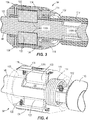
FIG. 3 is a cross-sectional view of the length adjustment assembly ofFIG. 1 , taken along lines 3-3 shown inFIG. 1 . -
FIG. 4 is a partial perspective view of the length adjustment assembly ofFIG. 1 , with portions removed for clarity. -
FIG. 5 is a perspective view of a handle member of the bolt cutter ofFIG. 1 . -
FIG. 6 is a partial perspective view of the bolt cutter ofFIG. 1 , with portions removed for clarity. -
FIG. 7 is an exploded view of the angle adjustment assembly ofFIG. 1 . -
FIG. 8A is a cross-sectional view of the angle adjustment assembly ofFIG. 1 in a locked position, taken alonglines 8A-8A shown inFIG. 1 . -
FIG. 8B is a cross-sectional view of the angle adjustment assembly ofFIG. 1 in an unlocked position, taken alonglines 8A-8A shown inFIG. 1 . -
FIG. 9 is a side view of the bolt cutter ofFIG. 1 , in a first configuration. -
FIG. 10 is a side view of the bolt cutter ofFIG. 1 , in a second configuration. -
FIG. 11 is a side view of the bolt cutter ofFIG. 1 , in a third configuration. -
FIG. 12 is a perspective view of a bolt cutter with adjustable handles including length adjustment assemblies and angle adjustment assemblies in accordance with another embodiment of the invention. - Before any embodiments of the invention are explained in detail, it is to be understood that the invention is not limited in its application to the details of construction and the arrangement of components set forth in the following description or illustrated in the following drawings. The invention is capable of other embodiments and of being practiced or of being carried out in various ways.
- With reference to
FIGS. 1-2 , abolt cutter 10 is illustrated including acutting head 14, a firstadjustable handle 18, and a secondadjustable handle 22. Thecutting head 14 includes afirst cutting blade 26 and asecond cutting blade 30 coupled together byplates 34 andcorresponding fasteners 38. Thefirst cutting blade 26 and thesecond cutting blade 30 are pivotable about a pin 42 (FIG. 6 ) that is sandwiched between theplates 34. Thepin 42 allows the first andsecond cutting blades FIG. 6 ) defined by thepin 42. Specifically, the first andsecond cutting blades blades FIG. 9 ) and a closed position (i.e., with the cutting portions of theblades FIG. 1 ). As the first andsecond blades blades - With reference to
FIG. 6 , thecutting head 14 further includes acompound hinge 50 to increase the cutting force of theblades adjustable handles compound hinge 50 includes afirst link 54 coupled to thefirst cutting blade 26 and asecond link 58 coupled to thesecond cutting blade 30. In particular, thefirst link 54 is pivotally coupled to thefirst cutting blade 26 about apivot axis 62 defined by afastener 66, and thesecond link 58 is pivotally coupled to thesecond cutting blade 30 about apivot axis 70 defined by afastener 74. Thefirst link 54 and thesecond link 58 are also pivotally coupled to each other about apivot axis 78 defined by afastener 82. As explained in greater detail below, the firstadjustable handle 18 is pivotally coupled to thefirst link 54 about apivot axis 86 and the secondadjustable handle 22 is pivotally coupled to thesecond link 58 about apivot axis 90. - With reference to
FIGS. 1-5 , the first and secondadjustable handles adjustable handles cutting head 14. Specifically, the first and secondadjustable handles first handle member 98 and asecond handle member 102 that telescopically receives thefirst handle member 98 within abore 106 formed in the second handle member 102 (FIG. 3 ). In the illustrated embodiment, thesecond handle member 102 also includes agrip portion 110, formed by, for example, an over-molding process. With reference toFIGS. 3 and 4 , thelength adjustment assembly 94 couples thefirst handle member 98 to thesecond handle member 102. In particular, thelength adjustment assembly 94 is movable between a locked position (FIGS. 3-4 ) in which thefirst handle member 98 is fixed relative to thesecond handle member 102, and an unlocked position (i.e., a released position) (not shown) in which thefirst handle member 98 is movable with respect to thesecond handle member 102. Thelength adjustment assembly 94 includes a spring 114 (i.e., a biasing member) to bias thelength adjustment assembly 94 toward the locked position. In the illustrated embodiment, thespring 114 is a torsional spring. - With continued reference to
FIGS. 3 and 4 , the length adjustment assembly includes a rotatable collar 118 (i.e., a movable lock) with two radially inwardly extendingprotrusions 122. In the illustrated embodiment, theprotrusions 122 are spaced approximately 180 degrees apart. With reference toFIG. 5 , aslot 126 is formed on a first side of thefirst handle member 94, and asimilar slot 126 is formed on an opposite, second side of thefirst handle member 94. Theprotrusions 122 are received within thecorresponding slots 126. Each of theslots 126 includes threegrooves protrusion 122 when thelength adjustment assembly 94 is in the locked position. Each of thegrooves adjustable handle 94 extends from thecutting head 14. Thespring 114 biases thecollar 118 to rotate in order to urge theprotrusions 122 into one of thegrooves 130A-130C formed in the telescopingfirst handle member 98. When theprotrusion 122 is received within thegroove 130A-130C, thefirst handle member 98 is locked with respect to thesecond handle member 102. In the illustrated embodiment, therotatable collar 118 is mounted for rotation about thesecond handle member 102. In alternative embodiments, therotatable collar 118 is mounted for rotation about thefirst handle member 98 and theslot 126 is formed on thesecond handle member 102. In further alternative embodiments, thesecond handle member 102 may be telescopically received within thefirst handle member 98. - With continued reference to
FIGS. 3 and 4 , theprotrusions 122 are formed as part of aremovable cover 134 that is secured to therotatable collar 118 by afastener 138. In the illustrated embodiment, theremovable cover 134 includes indicia indicating which direction the user needs to rotate thecollar 118 in order to unlock thelength adjustment assembly 94. A fastener 142 (FIG. 4 ) is secured to thesecond handle member 102 and is received within theslot 126 in order to prevent thefirst handle member 98 from being completely removed from thebore 106 of thesecond handle member 102. - To adjust the length of the
adjustable handle 18, 22 a user rotates thecollar 118, removing theprotrusions 122 from thegrooves 130A-130C to once again allow the telescopingfirst handle member 98 to slide relative to thesecond handle member 102. The adjustable handles 18, 22 define a length 146, 150, respectively, that thehandles head 14. Thelength adjustment assembly 94 selectively locks and unlocks the telescoping first handlemembers 98 in order to adjust the lengths 146, 150. For example, theprotrusions 122 are received within thefirst grooves 130A to secure theadjustable handles first length FIG. 1 ), and theprotrusions 122 are received within thethird grooves 130C to secure theadjustable handles second length FIG. 2 ) (i.e., an extended position). Thesecond length first length adjustable handle 18 can be adjusted to be shorter or longer than the length 150 of the second adjustable handle 22 (see, for example,FIG. 11 ). In other words, thelength adjustment assemblies 94 are operable independent of each other. Increasing the lengths 146, 150 of theadjustable handles - With reference to
FIGS. 6-8B , the first and secondadjustable handles adjustable handles head 14. In other words, the angular position of the first and secondadjustable handles head 14, without movement of the cuttinghead 14, by actuation of theangle adjustment assembly 154. With reference toFIG. 7 , thefirst link 54 of thehinge 50 defines aslot 158 into which anend 162 of thefirst handle member 98 is received. Thefirst handle member 98 includes ahandle bore 166 and thehinge 50 of the cuttinghead 14 includes ahinge bore 170 formed in thefirst link 54. Specifically, the hinge bore 170 is formed in afirst flange 174 and asecond flange 178 of thefirst link 54. Thefirst flange 174 and thesecond flange 178 at least partially define theslot 158. The handle bore 166 and the hinge bore 170 define thepivot axis adjustable handle hinge 50 of the cuttinghead 14. In particular, theangle adjustment assembly 154 allows a user to change the position of theadjustable handle teeth 182A, and the hinge bore 170 includesteeth 182B formed in thefirst flange 174 andteeth 182C formed in thesecond flange 178. - With reference to
FIG. 7 , theangle adjustment assembly 154 includes aplunger 186 received within the handle bore 166 and the hinge bore 170. Theplunger 186 includes a firsttoothed section 190, a secondtoothed section 194, a first smooth section 198 (i.e., non-toothed sections), and a secondsmooth section 202. In the illustrated embodiment, the secondsmooth section 202 is positioned between the firsttoothed section 190 and the secondtoothed section 194. Theangle adjustment assembly 154 further includes a spring 206 (i.e., a biasing member). In the illustrated embodiment, thespring 206 includes spring washers. Theangle adjustment assembly 154 further includes abutton 210 secured to theplunger 186 at afirst end 214 by afastener 218, and aplug 222 secured to theplunger 186 at a second,opposite end 226 by afastener 230. - With continued reference to
FIGS. 8A and 8B , theplunger 186 is received within the handle bore 166 and the hinge bore 170. In the illustrated embodiment, thespring 206 is positioned between theplunger 186 and thebutton 210 such that theplunger 186 is biased into the position shown inFIG. 8A . The position shown inFIG. 8A is a locked position with thetoothed sections plunger 186 in engagement with theteeth bores toothed section 190 engages both thefirst handle member 98 and thefirst flange 174, and the secondtoothed section 194 engages thesecond flange 178. The position shown inFIG. 8B is an unlocked position (i.e., a released position) with thetoothed sections plunger 186 disengaged from (i.e., removed from, misaligned with, etc.) theteeth first flange 174 and the second flange 178) such that thesmooth sections plunger 186 are aligned with thefirst flange 174 and thesecond flange 178. In particular, the firstsmooth section 198 is aligned with theteeth 182B in the hinge bore 170 of thefirst flange 174 and the secondsmooth section 202 is aligned with theteeth 182C in the hinge bore 170 of thesecond flange 178. In the unlocked position ofFIG. 8B , the firsttoothed section 190 remains engaged with theteeth 182A formed in the handle bore 166 of thefirst handle member 98, but thefirst handle member 98 is free to rotate about thepivot axis hinge 50 to adjust the angular position of thehandles head 14. - In other words, when the
plunger 186 is in the locked position (FIG. 8A ) thefirst handle member 98 of theadjustable handles plunger 186 is in the unlocked position (FIG. 8B ) thefirst handle member 98 is movable with respect to the hinge bore 170. In the locked position, thetoothed sections plunger 186 engage theteeth smooth sections plunger 186 are aligned with the hinge bore 170 while thetoothed section 190 of theplunger 186 remains engaged with thehandle bore 166. To adjust the angular position of thehandles head 14, a user depresses thebutton 210 in the direction 234 (FIG. 8B ) along theaxis springs 206, sliding theplunger 186 within thebores button 210 depressed, theangle adjustment assembly 154 is in the unlocked position and thehandles pivot axis handles button 210 and thespring 206 returns thetoothed sections FIG. 8A ). The angular range of adjustment for each of theadjustable handles first handle member 98 contactingend portions 238 of theslot 126 on thelinks - The
angle adjustment assembly 154 allows theadjustable handles head 14. In some embodiments, the ability to adjust the angular position allows for storing thehandles handles handles blades head 14 are still wide apart) and then thehandles head 14 in this closer angular configuration to allow the user to start the cut with his or her arms closer together to provide a better mechanical advantage. Then, once the cut has been started, thehandles head 14 to allow the user to readjust thehandles FIGS. 9 and10 . - With reference to
FIG. 9 , the cuttinghead 14 is in the open position (i.e., with the cutting portions of theblades handles handle 18 is positioned at anangle 242A with respect to a central axis 246 (i.e., the axis defined by the cutting portions of theblades handle 22 is positioned at anangle 250A with respect to thecentral axis 246. With reference toFIG. 10 , the user can adjust the position of thehandles angle adjustment assemblies 154, while keeping the cuttinghead 14 in the open position. More specifically, thehandle 18 is now positioned at anangle 242B with respect to thecentral axis 246 and thehandle 22 is positioned at anangle 250B with respect to thecentral axis 246. Theangles angles bolt cutter 10 as configured inFIG. 10 , the user can start the cut with his or her arms closer together to provide a better mechanical advantage and improved comfort. The angle 242 of the firstadjustable handle 18 can be adjusted to be smaller or larger than the angle 250 of the second adjustable handle 22 (see, for example,FIG. 11 ). In other words, thelength adjustment assemblies 154 are operable independent of each other. - Additionally, the angularly-
adjustable handles FIG. 11 , thefirst handle 18 can extend a first length 146C from the cuttinghead 14 and extend from thecentral axis 246 at afirst angle 242C. Thesecond handle 22 can extend a second length 150C from the cuttinghead 14 and extend from thecentral axis 246 at asecond angle 250C. The second length 150C is larger than the first length 146C and thesecond angle 250C is larger than thefirst angle 242C. In the configuration shown inFIG. 11 , the secondadjustable handle 22 can be pivoted approximately parallel to awork surface 254 such that a user can, for example, stand on thehandle 22, and with the firstadjustable handle 18 up in the air, the user can use a hand to apply pressure to secondadjustable handle 18 to close the cuttinghead 14, making a cut. Additionally, theadjustable handles - With reference to
FIG. 12 , abolt cutter 310 according to another embodiment is illustrated. Thebolt cutter 310 is similar to thebolt cutter 10, and only the differences are described herein, with similar components identified with similar reference numerals incremented by 300. Thebolt cutter 310 includesadjustable handles first handle member 398 and asecond handle member 402. Thefirst handle member 398 includes anextension portion 399 that is positioned between anend 462 of thefirst handle member 398 and aslot 426. Theextension portion 399 may include a tapered shape. Theextension portion 399 increases the overall length of the adjustable handles. - In some embodiments of the invention, the bolt cutter may include one or more length adjustment mechanisms and no angle adjustment mechanisms. In further embodiments of the invention, the bolt cutter may include one or more angle adjustment mechanisms and no length adjustment mechanism.
- Although the invention had been described in detail with reference to a bolt cutter, other embodiments incorporate the invention on other types of cutters or manually operated tools (e.g., shears, scissors, trimmers, etc.).
- Although the invention has been described in detail with reference to certain preferred embodiments, variations and modifications exist within the scope and spirit of one or more independent aspects of the invention as described. Various features and advantages of the invention are set forth in the following numbered clauses and the claims.
- Clause 1. A cutter comprising:
- a cutting head; and
- an adjustable handle pivotally coupled to the cutting head,
- wherein the adjustable handle includes a first adjustment assembly to change a length the adjustable handle extends from the cutting head, and
- wherein the adjustable handle includes a second adjustment assembly to change the position of the adjustable handle with respect to the cutting head.
- Clause 2. The cutter of clause 1, wherein the adjustable handle includes a first handle member, a second handle member, and wherein the first adjustment assembly couples the first handle member to the second handle member.
-
Clause 3. The cutter of clause 2, wherein the first handle member is telescopically received within the second handle member. - Clause 4. The cutter of clause 2, wherein the first adjustment assembly is movable between a locked position in which the first handle member is fixed relative to the second handle member and an unlocked position in which the first handle member is movable with respect to the second handle member.
- Clause 5. The cutter of clause 4, wherein the first adjustment assembly further comprises a spring to bias the first adjustment assembly toward the locked position.
- Clause 6. The cutter of clause 2, wherein a slot is formed on the first handle member and the first adjustment assembly includes a movable lock with a protrusion that is received within the slot.
- Clause 7. The cutter of clause 6, wherein the slot includes a plurality of grooves to receive the protrusion when the first adjustment assembly is in a locked position, wherein each of the plurality of grooves corresponds to a different length the adjustable handle extends from the cutting head.
- Clause 8. The cutter of clause 6, wherein the movable lock is a rotatable collar mounted for rotation about the second handle member.
- Clause 9. The cutter of clause 1, wherein the cutting head further includes a hinge coupled to the adjustable handle.
-
Clause 10. The cutter of clause 9, wherein the second adjustment assembly is movable between a locked position in which the adjustable handle is fixed with respect to the hinge and an unlocked position in which the adjustable handle is movable with respect to the hinge. - Clause 11. The cutter of
clause 10, wherein the second adjustment assembly further comprises a spring to bias the second adjustment assembly toward the locked position. - Clause 12. The cutter of clause 11, wherein the adjustable handle includes a handle bore and the hinge includes a hinge bore, and
wherein the handle bore and the hinge bore define a pivoting axis about which the adjustable handle pivots with respect to the hinge. - Clause 13. The cutter of clause 12, wherein the second adjustment assembly includes a plunger received within the handle bore and the hinge bore, the plunger includes a toothed section, and wherein the handle bore and the hinge bore each include a plurality of teeth.
-
Clause 14. The cutter of clause 13, wherein when the second adjustment assembly is in the locked position, the toothed section of the plunger engages the plurality of teeth in the handle bore and the hinge bore, and when the second adjustment assembly is in the unlocked position, the toothed section of the plunger disengages the plurality of teeth in the hinge bore. - Clause 15. A cutter comprising:
- a cutting head including a first bore; and
- an adjustable handle pivotally coupled to the cutting head, the adjustable handle including a second bore and an angle adjustment assembly to change the position of the adjustable handle with respect to the first bore,
- the first bore and the second bore define an axis about which the adjustable handle pivots with respect to the cutting head,
- wherein the angle adjustment assembly includes a plunger received within the first bore and the second bore, and
- wherein the plunger is movable between a locked position in which the adjustable handle is fixed with respect to the first bore and an unlocked position in which the adjustable handle is movable with respect to the first bore.
- Clause 16. The cutter of clause 15, wherein the plunger is movable between the locked position and the unlocked position along the axis.
- Clause 17. The cutter of clause 15, wherein the plunger is biased by a spring toward the locked position, and a user depresses the plunger to move the plunger toward the unlocked position.
-
Clause 18. The cutter of clause 15, wherein the first bore and the second bore each include a plurality of teeth and the plunger includes a toothed section, and
wherein when the plunger is in the locked position, the toothed section of the plunger engages the plurality of teeth in the first bore and the second bore, and
when the plunger is in the unlocked position, the toothed section of the plunger disengages the plurality of teeth in the first bore. - Clause 19. The cutter of
clause 18, wherein the first bore is formed in a first flange and a second flange, and wherein the toothed section of the plunger includes a first toothed section and a second toothed section, and
wherein the plunger further includes a first smooth section and a second smooth section, the second smooth section is positioned between the first toothed section and second toothed section,
when the plunger is in the locked position, the first toothed section of the plunger engages the plurality of teeth in the first bore of the first flange and the second toothed section of the plunger engages the plurality of teeth in the first bore of the second flange, and
when the plunger is in the unlocked position, the first smooth section of the plunger is aligned with the plurality of teeth in the first bore of the first flange and the second smooth section of the plunger is aligned with the plurality of teeth in the first bore of the second flange. - Clause 20. A cutter comprising:
- a cutting head;
- a first handle coupled to the cutting head, the first handle extends a first length from the cutting head and extends from a central axis at a first angle; and
- a second handle coupled to the cutting head, the second handle extends a second length from the cutting head, the second length is larger than the first length, and the second handle extends from the central axis at a second angle, the second angle is larger than the first angle.
- Clause 21. The cutter of clause 20, wherein the second length is adjustable by a user.
-
Clause 22. The cutter of clause 20, wherein the second angle is adjustable by a user.
Claims (8)
- A cutter comprising:a cutting head including a first bore; andan adjustable handle pivotally coupled to the cutting head, the adjustable handle including a second bore and an angle adjustment assembly to change the position of the adjustable handle with respect to the first bore,the first bore and the second bore define an axis about which the adjustable handle pivots with respect to the cutting head,wherein the angle adjustment assembly includes a plunger received within the first bore and the second bore, andwherein the plunger is movable between a locked position in which the adjustable handle is fixed with respect to the first bore and an unlocked position in which the adjustable handle is movable with respect to the first bore.
- The cutter of claim 1, wherein the plunger is movable between the locked position and the unlocked position along the axis.
- The cutter of claim 1, wherein the plunger is biased by a spring toward the locked position, and a user depresses the plunger to move the plunger toward the unlocked position.
- The cutter of claim 1, wherein the first bore and the second bore each include a plurality of teeth and the plunger includes a toothed section, and
wherein when the plunger is in the locked position, the toothed section of the plunger engages the plurality of teeth in the first bore and the second bore, and
when the plunger is in the unlocked position, the toothed section of the plunger disengages the plurality of teeth in the first bore. - The cutter of claim 4, wherein the first bore is formed in a first flange and a second flange, and wherein the toothed section of the plunger includes a first toothed section and a second toothed section, and
wherein the plunger further includes a first smooth section and a second smooth section, the second smooth section is positioned between the first toothed section and second toothed section,
when the plunger is in the locked position, the first toothed section of the plunger engages the plurality of teeth in the first bore of the first flange and the second toothed section of the plunger engages the plurality of teeth in the first bore of the second flange, and
when the plunger is in the unlocked position, the first smooth section of the plunger is aligned with the plurality of teeth in the first bore of the first flange and the second smooth section of the plunger is aligned with the plurality of teeth in the first bore of the second flange. - A cutter comprising:a cutting head;a first handle coupled to the cutting head, the first handle extends a first length from the cutting head and extends from a central axis at a first angle; anda second handle coupled to the cutting head, the second handle extends a second length from the cutting head, the second length is larger than the first length, and the second handle extends from the central axis at a second angle, the second angle is larger than the first angle.
- The cutter of claim 6, wherein the second length is adjustable by a user.
- The cutter of claim 6, wherein the second angle is adjustable by a user.
Applications Claiming Priority (3)
| Application Number | Priority Date | Filing Date | Title |
|---|---|---|---|
| US201562265536P | 2015-12-10 | 2015-12-10 | |
| EP16873912.6A EP3386688B1 (en) | 2015-12-10 | 2016-12-09 | Bolt cutter |
| PCT/US2016/065822 WO2017100567A1 (en) | 2015-12-10 | 2016-12-09 | Bolt cutter |
Related Parent Applications (2)
| Application Number | Title | Priority Date | Filing Date |
|---|---|---|---|
| EP16873912.6A Division EP3386688B1 (en) | 2015-12-10 | 2016-12-09 | Bolt cutter |
| EP16873912.6A Division-Into EP3386688B1 (en) | 2015-12-10 | 2016-12-09 | Bolt cutter |
Publications (2)
| Publication Number | Publication Date |
|---|---|
| EP3845348A1 true EP3845348A1 (en) | 2021-07-07 |
| EP3845348B1 EP3845348B1 (en) | 2026-08-12 |
Family
ID=59013607
Family Applications (2)
| Application Number | Title | Priority Date | Filing Date |
|---|---|---|---|
| EP21158758.9A Active EP3845348B1 (en) | 2015-12-10 | 2016-12-09 | Bolt cutter |
| EP16873912.6A Active EP3386688B1 (en) | 2015-12-10 | 2016-12-09 | Bolt cutter |
Family Applications After (1)
| Application Number | Title | Priority Date | Filing Date |
|---|---|---|---|
| EP16873912.6A Active EP3386688B1 (en) | 2015-12-10 | 2016-12-09 | Bolt cutter |
Country Status (5)
| Country | Link |
|---|---|
| US (4) | US10343295B2 (en) |
| EP (2) | EP3845348B1 (en) |
| CN (1) | CN208231843U (en) |
| TW (1) | TWM546298U (en) |
| WO (1) | WO2017100567A1 (en) |
Families Citing this family (10)
| Publication number | Priority date | Publication date | Assignee | Title |
|---|---|---|---|---|
| US11007658B2 (en) * | 2009-05-11 | 2021-05-18 | Roger J. Malcolm | Fiber-resin composite bolt cutter tool |
| US10343295B2 (en) | 2015-12-10 | 2019-07-09 | Milwaukee Electric Tool Corporation | Bolt cutter |
| JP7049341B2 (en) * | 2016-12-14 | 2022-04-06 | 杭州巨星科技股▲ふん▼有限公司 | How to adjust the angle between the retractable handheld device and the handheld part |
| CN112135704B (en) * | 2018-03-30 | 2023-08-25 | 米沃奇电动工具公司 | bolt cutter |
| US11465219B2 (en) * | 2020-01-29 | 2022-10-11 | Js Products, Inc. | Folding handle for tools and tools having folding handles |
| US20230053854A1 (en) * | 2021-08-17 | 2023-02-23 | Zhuji Itop Hardware Tools Co., Ltd. | Clamping plier facilitating cutting |
| CN215825210U (en) * | 2021-09-23 | 2022-02-15 | 诸暨市艾拓五金工具有限公司 | Clamp head of clamp and clamp |
| US20230347533A1 (en) * | 2022-04-27 | 2023-11-02 | Milwaukee Electric Tool Corporation | Bolt cutter |
| US12208504B2 (en) * | 2022-05-10 | 2025-01-28 | Yih Cheng Factory Co., Ltd. | Hand tool with rotary handle |
| US12533724B2 (en) | 2023-09-11 | 2026-01-27 | Js Products, Inc. | Fitting crimping tool with check gauge mount |
Citations (6)
| Publication number | Priority date | Publication date | Assignee | Title |
|---|---|---|---|---|
| DE202004013591U1 (en) * | 2004-08-31 | 2004-12-16 | Hsien, Chih Ching, Fengyuan | Pliers or tongs, comprising extendable handles with outer layer fixed in changed position |
| US6883208B1 (en) * | 2003-03-28 | 2005-04-26 | Yao-Chung Huang | Hedge shear extendable handle enhanced structure |
| US20060168818A1 (en) * | 2005-01-28 | 2006-08-03 | Outen James T | Multi-position locking tool |
| US20090007733A1 (en) * | 2007-07-05 | 2009-01-08 | Ibt Holding, Llc | Clamping and cutting apparatus with adjustable head |
| DE202008008012U1 (en) * | 2008-01-31 | 2009-06-18 | Weidmüller Interface GmbH & Co. KG | pincer grasp |
| US20140059808A1 (en) * | 2012-08-29 | 2014-03-06 | Thomas Lin | Press button-controlled retractable bar |
Family Cites Families (83)
| Publication number | Priority date | Publication date | Assignee | Title |
|---|---|---|---|---|
| US351339A (en) | 1886-10-19 | Bolt-cutter | ||
| US444635A (en) | 1891-01-13 | Bolt and rivet cutter | ||
| US1851771A (en) | 1931-04-28 | 1932-03-29 | William M Keith | Clipper |
| US2020242A (en) * | 1935-01-03 | 1935-11-05 | Porter Inc H K | Swivel head tool |
| US2382307A (en) | 1944-08-15 | 1945-08-14 | Porter Inc H K | Multiple lever tool |
| US2587586A (en) | 1949-06-24 | 1952-03-04 | Bernardi Alfredo Natale | Lawn trimmer and shrubbery pruner |
| US2685130A (en) | 1952-02-12 | 1954-08-03 | Porter Inc H K | Adjustable multiple lever tool |
| US2921773A (en) * | 1958-03-19 | 1960-01-19 | Hoelzer Bruce | Craftsman's adjustable pry bar |
| GB1098292A (en) | 1963-10-31 | 1968-01-10 | Peter James Wilson | Improvements in and relating to gripping and/or cutting tools |
| US3340611A (en) | 1966-07-18 | 1967-09-12 | Emerson Electric Co | Bolt cutter having handles interlinked with cam means and gear means |
| AT290429B (en) | 1967-11-10 | 1971-06-11 | Wegerhoff H Alarm Werkzeug | Adjustable bolt cutter |
| US3574938A (en) | 1968-11-22 | 1971-04-13 | Thomas M Porter | Jaw mounted adjusting means for cutting tool |
| US3733626A (en) | 1971-09-21 | 1973-05-22 | Sargent & Co | Compound action tool with wire stripper and bolt cutter |
| FR2261101B1 (en) | 1974-02-18 | 1976-12-03 | Stephanoises Forges | |
| US4144737A (en) | 1977-11-01 | 1979-03-20 | Thomas & Betts Corporation | Adjusting mechanism for a tool |
| US4505038A (en) * | 1983-11-21 | 1985-03-19 | H.K. Porter, Inc. | Compound lever tools from sheet metal |
| DE3628004A1 (en) | 1986-08-18 | 1988-02-25 | Langenstein Feld Garten | WORKING DEVICE, LIKE GARDEN EQUIPMENT, CLEANING DEVICE OR THE LIKE. |
| DE8803016U1 (en) | 1988-03-05 | 1989-07-06 | Knipex-Werk C. Gustav Putsch, 5600 Wuppertal | Center cutter |
| US4964216A (en) | 1988-07-05 | 1990-10-23 | Fiskars Oy Ab | Torque limiting device for shears |
| US5261303A (en) | 1992-03-23 | 1993-11-16 | Strippgen Walter E | Rod cutter |
| WO1995005271A1 (en) | 1993-08-12 | 1995-02-23 | Cooper Industries, Inc. | Improved bolt cutter |
| US5404616A (en) | 1993-09-30 | 1995-04-11 | Carmien; Joseph A. | Hand tool with removable handle |
| US5581838A (en) * | 1995-04-07 | 1996-12-10 | Rocco; Anthony C. | Articulating toothbrush assembly |
| EP0783935A3 (en) * | 1996-01-15 | 1997-07-23 | Gustav Klauke GmbH | Cutting tool, like diagonal cutting nipper, with lever transmission |
| US6085425A (en) | 1996-07-09 | 2000-07-11 | Kmedic Inc. | Surgical cutter |
| US5862597A (en) * | 1997-02-10 | 1999-01-26 | Juros; Karel B. F. | Super bolt cutter |
| US5988027A (en) | 1997-05-14 | 1999-11-23 | Lenox - Maclaren | Surgical rod cutter |
| US5933965A (en) | 1997-07-12 | 1999-08-10 | Fiskars Inc. | Extendable tool |
| US5974670A (en) | 1997-10-30 | 1999-11-02 | Hsieh; Chih-Ching | Multipurpose tool |
| SE512072C2 (en) | 1999-02-25 | 2000-01-24 | Kapman Ab | Adjustable bolt cutter |
| AUPQ316699A0 (en) | 1999-09-28 | 1999-10-21 | Petts, Andax | Wrench |
| US6370992B1 (en) * | 2000-12-04 | 2002-04-16 | Hsieh Shih-Kuei | Pliers for use in narrow space |
| GB2369794B (en) | 2000-12-06 | 2003-11-19 | Shih-Kuei Hsieh | Pliers for use in narrow space |
| US20020073557A1 (en) * | 2000-12-19 | 2002-06-20 | Ho Cheng Garden Tools Co., Ltd. | Expandable tubular body |
| US6546596B2 (en) * | 2001-01-08 | 2003-04-15 | Rick V. Grote | Extension pole for tools |
| TW547585U (en) | 2001-12-31 | 2003-08-11 | You-Tang Lin | Non-circular bar-shaped objects capable of adjusting length |
| FI114291B (en) | 2002-05-28 | 2004-09-30 | Fiskars Consumer Oy Ab | Handles for work tools or the like |
| US20040181904A1 (en) | 2002-12-18 | 2004-09-23 | Gordon Steltzer | Foldable forcible entry tools |
| US6959629B2 (en) * | 2003-08-15 | 2005-11-01 | Chih-Ching Hsien | Hand tool having a retractable handle structure |
| US20050204873A1 (en) | 2004-03-22 | 2005-09-22 | Ana Giovanni S | Tool handle extension |
| US7178431B2 (en) | 2004-08-04 | 2007-02-20 | Chih-Ching Hsien | Extendable handles for hand tools |
| FR2876931A1 (en) | 2004-10-22 | 2006-04-28 | Archilab Soc Par Actions Simpl | Bolt cutter for use by e.g. bricklayer, has jaws articulated by component and shafts made of composite material and comprising gripping handles at their one end, where one shaft has articulated support base supporting cutter in top position |
| US20060090613A1 (en) * | 2004-11-02 | 2006-05-04 | Chih-Ching Hsieh | Pivotal retaining device of hand tool |
| TWM277257U (en) | 2005-01-17 | 2005-10-11 | Wise Ct Prec Appliance Co Ltd | Veering positioning structure of retractable tube |
| FR2882676B3 (en) | 2005-03-04 | 2007-01-19 | Chih Ching Hsien | DECOUPAGE DEVICE THAT CAN BE INCLINED |
| US7415911B2 (en) * | 2005-05-18 | 2008-08-26 | Melissa Cole, legal representative | Adjustable tools |
| US7682099B2 (en) * | 2006-01-24 | 2010-03-23 | Cole Charles A | Indexable, lockable pivoting mechanism for hand tool |
| DE102006017485B4 (en) * | 2006-04-13 | 2014-06-05 | Merck Patent Gmbh | Biphenyl-Metal Complexes - Monomers and Oligomers Triplet emitters for OLED applications |
| US20070262597A1 (en) | 2006-05-11 | 2007-11-15 | Nicholas Ramos | Reaching apparatus with telescoping handles |
| US20080016700A1 (en) | 2006-07-18 | 2008-01-24 | Hernandez Hector R | High leverage bolt cutter |
| US7574806B2 (en) | 2006-10-10 | 2009-08-18 | Kuang-Pin Wang | Adjustment structure of garden shears |
| US7694387B1 (en) | 2006-12-28 | 2010-04-13 | Ho Cheng Garden Tools Co., Ltd. | Retractable handle assembly |
| US20080155785A1 (en) * | 2006-12-29 | 2008-07-03 | Chia Yu Chen | Telescopic hand tool |
| US7628382B2 (en) * | 2007-01-30 | 2009-12-08 | Charles Cole | Nail extractor, moulding remover and pry bar tool with indexable head |
| US7721391B2 (en) * | 2007-05-10 | 2010-05-25 | The Wooster Brush Company | Quick release lock mechanisms for handle extensions |
| WO2008144235A1 (en) * | 2007-05-18 | 2008-11-27 | Aj Manufacturing Co., Inc. | Indexable pry tool and splined coupling arrangement therefor |
| CN201067918Y (en) | 2007-07-14 | 2008-06-04 | 徐州金虎工具制造有限公司 | Bolt clippers with straight handle |
| US7878094B2 (en) * | 2007-10-04 | 2011-02-01 | Stanley Black & Decker, Inc. | Tool with extendable handle |
| US8132308B2 (en) | 2007-11-20 | 2012-03-13 | Foley Michael J | Fastener extraction tool |
| US7774901B1 (en) | 2007-12-05 | 2010-08-17 | Ho Cheng Garden Tools Co., Ltd. | Retractable handle assembly for tool |
| DE102008003723B4 (en) | 2008-01-09 | 2018-11-22 | Knipex-Werk C. Gustav Putsch Kg | tongs |
| FR2929354B1 (en) | 2008-03-25 | 2010-03-19 | Rowenta Werke Gmbh | LATCHING DEVICE FOR TELESCOPIC ROD AND APPARATUS PROVIDED WITH SUCH A LOCKING DEVICE |
| US7717017B2 (en) | 2008-06-11 | 2010-05-18 | Mcbride Mark Tabin | Hand tool and method of using same |
| US8307557B1 (en) | 2008-12-17 | 2012-11-13 | Rodgers Timothy J | Foot operated cutter |
| US7854185B2 (en) | 2009-01-12 | 2010-12-21 | Tianjin Runshi Science Development Co., Ltd. | Ratchet pliers with adjustable jaw |
| US20100326248A1 (en) | 2009-06-30 | 2010-12-30 | Greg Owoc | Telescoping handle for tools having circular locking indents |
| US8511207B2 (en) * | 2009-07-03 | 2013-08-20 | Cheng-Wei Su | Rotation control device for a tool |
| TW201102237A (en) | 2009-07-03 | 2011-01-16 | Natura Innovation Ltd | Telescopic positioning structure of hand scissors |
| DE102009059198A1 (en) | 2009-12-17 | 2011-06-22 | KNIPEX-Werk C. Gustav Putsch KG, 42349 | tongs |
| WO2012033542A2 (en) * | 2010-09-10 | 2012-03-15 | Panosian Michael H | Bolt cutters with breakdown handles |
| US8490250B2 (en) * | 2010-12-06 | 2013-07-23 | Tcm Consulting Llc | Interlocking extension poles and tool holder |
| US20120174417A1 (en) | 2011-01-11 | 2012-07-12 | Ho Cheng Garden Tools Co., Ltd. | Handle system for garden shears |
| CN202225105U (en) | 2011-08-09 | 2012-05-23 | 润联(天津)五金工具有限公司 | Clamping tool with angle-changeable clamp handle |
| US8708312B2 (en) * | 2012-01-10 | 2014-04-29 | Rafal Stawarski | Pry bar |
| US8806720B2 (en) | 2012-01-24 | 2014-08-19 | Green Guard Industry Ltd. | Rack type telescopic handle of horticultural shears |
| US20130205601A1 (en) | 2012-02-15 | 2013-08-15 | Shih-Piao Wu | Gardening Shears Having Handles with Changeable Pivotal Angles |
| WO2015168818A1 (en) | 2014-05-05 | 2015-11-12 | 林有堂 | Telescopic rod for hand tool |
| US9205549B1 (en) * | 2014-07-15 | 2015-12-08 | Thomas Lin | Retractable bar for hand tool |
| US10343295B2 (en) * | 2015-12-10 | 2019-07-09 | Milwaukee Electric Tool Corporation | Bolt cutter |
| US9744662B1 (en) * | 2016-07-07 | 2017-08-29 | Derek Henry | Double-pin locking extensible handle |
| US10201131B1 (en) * | 2017-09-07 | 2019-02-12 | Ho Cheng Garden Tools Co. Ltd. | Foldable gardening shear |
| CN112135704B (en) * | 2018-03-30 | 2023-08-25 | 米沃奇电动工具公司 | bolt cutter |
| US20230347533A1 (en) * | 2022-04-27 | 2023-11-02 | Milwaukee Electric Tool Corporation | Bolt cutter |
-
2016
- 2016-12-09 US US15/374,031 patent/US10343295B2/en active Active
- 2016-12-09 EP EP21158758.9A patent/EP3845348B1/en active Active
- 2016-12-09 EP EP16873912.6A patent/EP3386688B1/en active Active
- 2016-12-09 WO PCT/US2016/065822 patent/WO2017100567A1/en not_active Ceased
- 2016-12-09 TW TW105218830U patent/TWM546298U/en not_active IP Right Cessation
- 2016-12-09 CN CN201690001438.4U patent/CN208231843U/en not_active Expired - Fee Related
-
2019
- 2019-06-10 US US16/436,563 patent/US11090822B2/en active Active
-
2021
- 2021-07-12 US US17/373,373 patent/US12157241B2/en active Active
-
2024
- 2024-10-25 US US18/927,069 patent/US20250050518A1/en active Pending
Patent Citations (6)
| Publication number | Priority date | Publication date | Assignee | Title |
|---|---|---|---|---|
| US6883208B1 (en) * | 2003-03-28 | 2005-04-26 | Yao-Chung Huang | Hedge shear extendable handle enhanced structure |
| DE202004013591U1 (en) * | 2004-08-31 | 2004-12-16 | Hsien, Chih Ching, Fengyuan | Pliers or tongs, comprising extendable handles with outer layer fixed in changed position |
| US20060168818A1 (en) * | 2005-01-28 | 2006-08-03 | Outen James T | Multi-position locking tool |
| US20090007733A1 (en) * | 2007-07-05 | 2009-01-08 | Ibt Holding, Llc | Clamping and cutting apparatus with adjustable head |
| DE202008008012U1 (en) * | 2008-01-31 | 2009-06-18 | Weidmüller Interface GmbH & Co. KG | pincer grasp |
| US20140059808A1 (en) * | 2012-08-29 | 2014-03-06 | Thomas Lin | Press button-controlled retractable bar |
Also Published As
| Publication number | Publication date |
|---|---|
| TWM546298U (en) | 2017-08-01 |
| US20170165852A1 (en) | 2017-06-15 |
| US20190291287A1 (en) | 2019-09-26 |
| EP3845348B1 (en) | 2026-08-12 |
| US10343295B2 (en) | 2019-07-09 |
| US20210339411A1 (en) | 2021-11-04 |
| EP3386688B1 (en) | 2021-04-07 |
| WO2017100567A1 (en) | 2017-06-15 |
| EP3386688A1 (en) | 2018-10-17 |
| CN208231843U (en) | 2018-12-14 |
| US11090822B2 (en) | 2021-08-17 |
| WO2017100567A8 (en) | 2018-04-26 |
| US12157241B2 (en) | 2024-12-03 |
| US20250050518A1 (en) | 2025-02-13 |
| EP3386688A4 (en) | 2020-03-04 |
Similar Documents
| Publication | Publication Date | Title |
|---|---|---|
| US20250050518A1 (en) | Bolt Cutter | |
| US11904450B2 (en) | Multi-function pliers | |
| US7921752B2 (en) | Enhanced multi-function hand tool | |
| US7028591B2 (en) | Multi-function tool with spring biased implement | |
| EP2976189B1 (en) | Foldable hand-held tool | |
| EP3192621B1 (en) | Miter saw | |
| EP2254736B1 (en) | Tool including a locking mechanism | |
| EP2189250B1 (en) | Locking pliers | |
| US4512051A (en) | Handtool | |
| US6282997B1 (en) | Multipurpose tool and components thereof | |
| EP3277466B1 (en) | Multi-function tool | |
| US20080236210A1 (en) | Discrete multitool locking method and apparatus | |
| US20060005397A1 (en) | Folding tool with blade locking mechanism | |
| US8739415B2 (en) | Two-stage force multiplier tin snips | |
| US20120023756A1 (en) | Hand cutting tool | |
| CA2622424A1 (en) | Multipurpose hand tool with rotatable handle | |
| US6941663B2 (en) | Cable cutter | |
| US9211649B1 (en) | Knife with folding guard |
Legal Events
| Date | Code | Title | Description |
|---|---|---|---|
| PUAI | Public reference made under article 153(3) epc to a published international application that has entered the european phase |
Free format text: ORIGINAL CODE: 0009012 |
|
| STAA | Information on the status of an ep patent application or granted ep patent |
Free format text: STATUS: THE APPLICATION HAS BEEN PUBLISHED |
|
| AC | Divisional application: reference to earlier application |
Ref document number: 3386688 Country of ref document: EP Kind code of ref document: P |
|
| AK | Designated contracting states |
Kind code of ref document: A1 Designated state(s): AL AT BE BG CH CY CZ DE DK EE ES FI FR GB GR HR HU IE IS IT LI LT LU LV MC MK MT NL NO PL PT RO RS SE SI SK SM TR |
|
| STAA | Information on the status of an ep patent application or granted ep patent |
Free format text: STATUS: REQUEST FOR EXAMINATION WAS MADE |
|
| 17P | Request for examination filed |
Effective date: 20211222 |
|
| RBV | Designated contracting states (corrected) |
Designated state(s): AL AT BE BG CH CY CZ DE DK EE ES FI FR GB GR HR HU IE IS IT LI LT LU LV MC MK MT NL NO PL PT RO RS SE SI SK SM TR |
|
| STAA | Information on the status of an ep patent application or granted ep patent |
Free format text: STATUS: EXAMINATION IS IN PROGRESS |
|
| 17Q | First examination report despatched |
Effective date: 20230215 |
|
| GRAP | Despatch of communication of intention to grant a patent |
Free format text: ORIGINAL CODE: EPIDOSNIGR1 |
|
| STAA | Information on the status of an ep patent application or granted ep patent |
Free format text: STATUS: GRANT OF PATENT IS INTENDED |
|
| INTG | Intention to grant announced |
Effective date: 20260325 |
|
| GRAS | Grant fee paid |
Free format text: ORIGINAL CODE: EPIDOSNIGR3 |
|
| GRAA | (expected) grant |
Free format text: ORIGINAL CODE: 0009210 |
|
| STAA | Information on the status of an ep patent application or granted ep patent |
Free format text: STATUS: THE PATENT HAS BEEN GRANTED |
|
| AC | Divisional application: reference to earlier application |
Ref document number: 3386688 Country of ref document: EP Kind code of ref document: P |
|
| AK | Designated contracting states |
Kind code of ref document: B1 Designated state(s): AL AT BE BG CH CY CZ DE DK EE ES FI FR GB GR HR HU IE IS IT LI LT LU LV MC MK MT NL NO PL PT RO RS SE SI SK SM TR |
|
| REG | Reference to a national code |
Ref country code: CH Ref legal event code: F10 Free format text: ST27 STATUS EVENT CODE: U-0-0-F10-F00 (AS PROVIDED BY THE NATIONAL OFFICE) Effective date: 20260812 Ref country code: GB Ref legal event code: FG4D |