EP3845293A1 - Gas purification device, ship with same, and gas purification method - Google Patents
Gas purification device, ship with same, and gas purification method Download PDFInfo
- Publication number
- EP3845293A1 EP3845293A1 EP19877394.7A EP19877394A EP3845293A1 EP 3845293 A1 EP3845293 A1 EP 3845293A1 EP 19877394 A EP19877394 A EP 19877394A EP 3845293 A1 EP3845293 A1 EP 3845293A1
- Authority
- EP
- European Patent Office
- Prior art keywords
- gas
- gas purification
- filter
- filter element
- purification apparatus
- Prior art date
- Legal status (The legal status is an assumption and is not a legal conclusion. Google has not performed a legal analysis and makes no representation as to the accuracy of the status listed.)
- Granted
Links
Images




Classifications
-
- B—PERFORMING OPERATIONS; TRANSPORTING
- B01—PHYSICAL OR CHEMICAL PROCESSES OR APPARATUS IN GENERAL
- B01D—SEPARATION
- B01D46/00—Filters or filtering processes specially modified for separating dispersed particles from gases or vapours
- B01D46/24—Particle separators, e.g. dust precipitators, using rigid hollow filter bodies
- B01D46/2403—Particle separators, e.g. dust precipitators, using rigid hollow filter bodies characterised by the physical shape or structure of the filtering element
-
- B—PERFORMING OPERATIONS; TRANSPORTING
- B01—PHYSICAL OR CHEMICAL PROCESSES OR APPARATUS IN GENERAL
- B01J—CHEMICAL OR PHYSICAL PROCESSES, e.g. CATALYSIS OR COLLOID CHEMISTRY; THEIR RELEVANT APPARATUS
- B01J35/00—Catalysts, in general, characterised by their form or physical properties
- B01J35/50—Catalysts, in general, characterised by their form or physical properties characterised by their shape or configuration
- B01J35/58—Fabrics or filaments
-
- B—PERFORMING OPERATIONS; TRANSPORTING
- B01—PHYSICAL OR CHEMICAL PROCESSES OR APPARATUS IN GENERAL
- B01D—SEPARATION
- B01D46/00—Filters or filtering processes specially modified for separating dispersed particles from gases or vapours
- B01D46/0027—Filters or filtering processes specially modified for separating dispersed particles from gases or vapours with additional separating or treating functions
- B01D46/0036—Filters or filtering processes specially modified for separating dispersed particles from gases or vapours with additional separating or treating functions by adsorption or absorption
-
- B—PERFORMING OPERATIONS; TRANSPORTING
- B01—PHYSICAL OR CHEMICAL PROCESSES OR APPARATUS IN GENERAL
- B01D—SEPARATION
- B01D46/00—Filters or filtering processes specially modified for separating dispersed particles from gases or vapours
- B01D46/66—Regeneration of the filtering material or filter elements inside the filter
-
- B—PERFORMING OPERATIONS; TRANSPORTING
- B01—PHYSICAL OR CHEMICAL PROCESSES OR APPARATUS IN GENERAL
- B01D—SEPARATION
- B01D53/00—Separation of gases or vapours; Recovering vapours of volatile solvents from gases; Chemical or biological purification of waste gases, e.g. engine exhaust gases, smoke, fumes, flue gases, aerosols
- B01D53/34—Chemical or biological purification of waste gases
- B01D53/46—Removing components of defined structure
- B01D53/48—Sulfur compounds
- B01D53/50—Sulfur oxides
- B01D53/508—Sulfur oxides by treating the gases with solids
-
- B—PERFORMING OPERATIONS; TRANSPORTING
- B01—PHYSICAL OR CHEMICAL PROCESSES OR APPARATUS IN GENERAL
- B01D—SEPARATION
- B01D53/00—Separation of gases or vapours; Recovering vapours of volatile solvents from gases; Chemical or biological purification of waste gases, e.g. engine exhaust gases, smoke, fumes, flue gases, aerosols
- B01D53/34—Chemical or biological purification of waste gases
- B01D53/46—Removing components of defined structure
- B01D53/62—Carbon oxides
-
- B—PERFORMING OPERATIONS; TRANSPORTING
- B01—PHYSICAL OR CHEMICAL PROCESSES OR APPARATUS IN GENERAL
- B01D—SEPARATION
- B01D53/00—Separation of gases or vapours; Recovering vapours of volatile solvents from gases; Chemical or biological purification of waste gases, e.g. engine exhaust gases, smoke, fumes, flue gases, aerosols
- B01D53/34—Chemical or biological purification of waste gases
- B01D53/74—General processes for purification of waste gases; Apparatus or devices specially adapted therefor
- B01D53/81—Solid phase processes
- B01D53/83—Solid phase processes with moving reactants
-
- B—PERFORMING OPERATIONS; TRANSPORTING
- B01—PHYSICAL OR CHEMICAL PROCESSES OR APPARATUS IN GENERAL
- B01D—SEPARATION
- B01D53/00—Separation of gases or vapours; Recovering vapours of volatile solvents from gases; Chemical or biological purification of waste gases, e.g. engine exhaust gases, smoke, fumes, flue gases, aerosols
- B01D53/34—Chemical or biological purification of waste gases
- B01D53/74—General processes for purification of waste gases; Apparatus or devices specially adapted therefor
- B01D53/86—Catalytic processes
- B01D53/8621—Removing nitrogen compounds
- B01D53/8625—Nitrogen oxides
- B01D53/8631—Processes characterised by a specific device
-
- B—PERFORMING OPERATIONS; TRANSPORTING
- B01—PHYSICAL OR CHEMICAL PROCESSES OR APPARATUS IN GENERAL
- B01D—SEPARATION
- B01D53/00—Separation of gases or vapours; Recovering vapours of volatile solvents from gases; Chemical or biological purification of waste gases, e.g. engine exhaust gases, smoke, fumes, flue gases, aerosols
- B01D53/34—Chemical or biological purification of waste gases
- B01D53/92—Chemical or biological purification of waste gases of engine exhaust gases
- B01D53/94—Chemical or biological purification of waste gases of engine exhaust gases by catalytic processes
- B01D53/9404—Removing only nitrogen compounds
- B01D53/9409—Nitrogen oxides
- B01D53/9431—Processes characterised by a specific device
-
- B—PERFORMING OPERATIONS; TRANSPORTING
- B63—SHIPS OR OTHER WATERBORNE VESSELS; RELATED EQUIPMENT
- B63H—MARINE PROPULSION OR STEERING
- B63H21/00—Use of propulsion power plant or units on vessels
- B63H21/32—Arrangements of propulsion power-unit exhaust uptakes; Funnels peculiar to vessels
-
- F—MECHANICAL ENGINEERING; LIGHTING; HEATING; WEAPONS; BLASTING
- F01—MACHINES OR ENGINES IN GENERAL; ENGINE PLANTS IN GENERAL; STEAM ENGINES
- F01N—GAS-FLOW SILENCERS OR EXHAUST APPARATUS FOR MACHINES OR ENGINES IN GENERAL; GAS-FLOW SILENCERS OR EXHAUST APPARATUS FOR INTERNAL-COMBUSTION ENGINES
- F01N13/00—Exhaust or silencing apparatus characterised by constructional features
-
- F—MECHANICAL ENGINEERING; LIGHTING; HEATING; WEAPONS; BLASTING
- F01—MACHINES OR ENGINES IN GENERAL; ENGINE PLANTS IN GENERAL; STEAM ENGINES
- F01N—GAS-FLOW SILENCERS OR EXHAUST APPARATUS FOR MACHINES OR ENGINES IN GENERAL; GAS-FLOW SILENCERS OR EXHAUST APPARATUS FOR INTERNAL-COMBUSTION ENGINES
- F01N3/00—Exhaust or silencing apparatus having means for purifying, rendering innocuous, or otherwise treating exhaust
- F01N3/02—Exhaust or silencing apparatus having means for purifying, rendering innocuous, or otherwise treating exhaust for cooling, or for removing solid constituents of, exhaust
- F01N3/021—Exhaust or silencing apparatus having means for purifying, rendering innocuous, or otherwise treating exhaust for cooling, or for removing solid constituents of, exhaust by means of filters
-
- F—MECHANICAL ENGINEERING; LIGHTING; HEATING; WEAPONS; BLASTING
- F01—MACHINES OR ENGINES IN GENERAL; ENGINE PLANTS IN GENERAL; STEAM ENGINES
- F01N—GAS-FLOW SILENCERS OR EXHAUST APPARATUS FOR MACHINES OR ENGINES IN GENERAL; GAS-FLOW SILENCERS OR EXHAUST APPARATUS FOR INTERNAL-COMBUSTION ENGINES
- F01N3/00—Exhaust or silencing apparatus having means for purifying, rendering innocuous, or otherwise treating exhaust
- F01N3/02—Exhaust or silencing apparatus having means for purifying, rendering innocuous, or otherwise treating exhaust for cooling, or for removing solid constituents of, exhaust
- F01N3/021—Exhaust or silencing apparatus having means for purifying, rendering innocuous, or otherwise treating exhaust for cooling, or for removing solid constituents of, exhaust by means of filters
- F01N3/033—Exhaust or silencing apparatus having means for purifying, rendering innocuous, or otherwise treating exhaust for cooling, or for removing solid constituents of, exhaust by means of filters in combination with other devices
- F01N3/035—Exhaust or silencing apparatus having means for purifying, rendering innocuous, or otherwise treating exhaust for cooling, or for removing solid constituents of, exhaust by means of filters in combination with other devices with catalytic reactors
-
- F—MECHANICAL ENGINEERING; LIGHTING; HEATING; WEAPONS; BLASTING
- F01—MACHINES OR ENGINES IN GENERAL; ENGINE PLANTS IN GENERAL; STEAM ENGINES
- F01N—GAS-FLOW SILENCERS OR EXHAUST APPARATUS FOR MACHINES OR ENGINES IN GENERAL; GAS-FLOW SILENCERS OR EXHAUST APPARATUS FOR INTERNAL-COMBUSTION ENGINES
- F01N3/00—Exhaust or silencing apparatus having means for purifying, rendering innocuous, or otherwise treating exhaust
- F01N3/02—Exhaust or silencing apparatus having means for purifying, rendering innocuous, or otherwise treating exhaust for cooling, or for removing solid constituents of, exhaust
- F01N3/04—Exhaust or silencing apparatus having means for purifying, rendering innocuous, or otherwise treating exhaust for cooling, or for removing solid constituents of, exhaust using liquids
-
- B—PERFORMING OPERATIONS; TRANSPORTING
- B01—PHYSICAL OR CHEMICAL PROCESSES OR APPARATUS IN GENERAL
- B01D—SEPARATION
- B01D2251/00—Reactants
- B01D2251/30—Alkali metal compounds
- B01D2251/304—Alkali metal compounds of sodium
-
- B—PERFORMING OPERATIONS; TRANSPORTING
- B01—PHYSICAL OR CHEMICAL PROCESSES OR APPARATUS IN GENERAL
- B01D—SEPARATION
- B01D2251/00—Reactants
- B01D2251/40—Alkaline earth metal or magnesium compounds
- B01D2251/404—Alkaline earth metal or magnesium compounds of calcium
-
- B—PERFORMING OPERATIONS; TRANSPORTING
- B01—PHYSICAL OR CHEMICAL PROCESSES OR APPARATUS IN GENERAL
- B01D—SEPARATION
- B01D2251/00—Reactants
- B01D2251/60—Inorganic bases or salts
- B01D2251/604—Hydroxides
-
- B—PERFORMING OPERATIONS; TRANSPORTING
- B01—PHYSICAL OR CHEMICAL PROCESSES OR APPARATUS IN GENERAL
- B01D—SEPARATION
- B01D2251/00—Reactants
- B01D2251/60—Inorganic bases or salts
- B01D2251/606—Carbonates
-
- B—PERFORMING OPERATIONS; TRANSPORTING
- B01—PHYSICAL OR CHEMICAL PROCESSES OR APPARATUS IN GENERAL
- B01D—SEPARATION
- B01D2253/00—Adsorbents used in seperation treatment of gases and vapours
- B01D2253/10—Inorganic adsorbents
- B01D2253/102—Carbon
-
- B—PERFORMING OPERATIONS; TRANSPORTING
- B01—PHYSICAL OR CHEMICAL PROCESSES OR APPARATUS IN GENERAL
- B01D—SEPARATION
- B01D2253/00—Adsorbents used in seperation treatment of gases and vapours
- B01D2253/10—Inorganic adsorbents
- B01D2253/112—Metals or metal compounds not provided for in B01D2253/104 or B01D2253/106
-
- B—PERFORMING OPERATIONS; TRANSPORTING
- B01—PHYSICAL OR CHEMICAL PROCESSES OR APPARATUS IN GENERAL
- B01D—SEPARATION
- B01D2255/00—Catalysts
- B01D2255/90—Physical characteristics of catalysts
- B01D2255/915—Catalyst supported on particulate filters
- B01D2255/9155—Wall flow filters
-
- B—PERFORMING OPERATIONS; TRANSPORTING
- B01—PHYSICAL OR CHEMICAL PROCESSES OR APPARATUS IN GENERAL
- B01D—SEPARATION
- B01D2257/00—Components to be removed
- B01D2257/30—Sulfur compounds
- B01D2257/302—Sulfur oxides
-
- B—PERFORMING OPERATIONS; TRANSPORTING
- B01—PHYSICAL OR CHEMICAL PROCESSES OR APPARATUS IN GENERAL
- B01D—SEPARATION
- B01D2257/00—Components to be removed
- B01D2257/40—Nitrogen compounds
- B01D2257/404—Nitrogen oxides other than dinitrogen oxide
-
- B—PERFORMING OPERATIONS; TRANSPORTING
- B01—PHYSICAL OR CHEMICAL PROCESSES OR APPARATUS IN GENERAL
- B01D—SEPARATION
- B01D2257/00—Components to be removed
- B01D2257/50—Carbon oxides
- B01D2257/504—Carbon dioxide
-
- B—PERFORMING OPERATIONS; TRANSPORTING
- B01—PHYSICAL OR CHEMICAL PROCESSES OR APPARATUS IN GENERAL
- B01D—SEPARATION
- B01D2258/00—Sources of waste gases
- B01D2258/01—Engine exhaust gases
-
- B—PERFORMING OPERATIONS; TRANSPORTING
- B01—PHYSICAL OR CHEMICAL PROCESSES OR APPARATUS IN GENERAL
- B01D—SEPARATION
- B01D2259/00—Type of treatment
- B01D2259/45—Gas separation or purification devices adapted for specific applications
- B01D2259/4566—Gas separation or purification devices adapted for specific applications for use in transportation means
-
- B—PERFORMING OPERATIONS; TRANSPORTING
- B01—PHYSICAL OR CHEMICAL PROCESSES OR APPARATUS IN GENERAL
- B01D—SEPARATION
- B01D2279/00—Filters adapted for separating dispersed particles from gases or vapours specially modified for specific uses
- B01D2279/30—Filters adapted for separating dispersed particles from gases or vapours specially modified for specific uses for treatment of exhaust gases from IC Engines
-
- B—PERFORMING OPERATIONS; TRANSPORTING
- B01—PHYSICAL OR CHEMICAL PROCESSES OR APPARATUS IN GENERAL
- B01D—SEPARATION
- B01D2279/00—Filters adapted for separating dispersed particles from gases or vapours specially modified for specific uses
- B01D2279/40—Filters adapted for separating dispersed particles from gases or vapours specially modified for specific uses for cleaning of environmental air, e.g. by filters installed on vehicles or on streets
-
- F—MECHANICAL ENGINEERING; LIGHTING; HEATING; WEAPONS; BLASTING
- F01—MACHINES OR ENGINES IN GENERAL; ENGINE PLANTS IN GENERAL; STEAM ENGINES
- F01N—GAS-FLOW SILENCERS OR EXHAUST APPARATUS FOR MACHINES OR ENGINES IN GENERAL; GAS-FLOW SILENCERS OR EXHAUST APPARATUS FOR INTERNAL-COMBUSTION ENGINES
- F01N2250/00—Combinations of different methods of purification
- F01N2250/02—Combinations of different methods of purification filtering and catalytic conversion
-
- F—MECHANICAL ENGINEERING; LIGHTING; HEATING; WEAPONS; BLASTING
- F01—MACHINES OR ENGINES IN GENERAL; ENGINE PLANTS IN GENERAL; STEAM ENGINES
- F01N—GAS-FLOW SILENCERS OR EXHAUST APPARATUS FOR MACHINES OR ENGINES IN GENERAL; GAS-FLOW SILENCERS OR EXHAUST APPARATUS FOR INTERNAL-COMBUSTION ENGINES
- F01N2330/00—Structure of catalyst support or particle filter
-
- F—MECHANICAL ENGINEERING; LIGHTING; HEATING; WEAPONS; BLASTING
- F01—MACHINES OR ENGINES IN GENERAL; ENGINE PLANTS IN GENERAL; STEAM ENGINES
- F01N—GAS-FLOW SILENCERS OR EXHAUST APPARATUS FOR MACHINES OR ENGINES IN GENERAL; GAS-FLOW SILENCERS OR EXHAUST APPARATUS FOR INTERNAL-COMBUSTION ENGINES
- F01N2570/00—Exhaust treating apparatus eliminating, absorbing or adsorbing specific elements or compounds
- F01N2570/04—Sulfur or sulfur oxides
-
- F—MECHANICAL ENGINEERING; LIGHTING; HEATING; WEAPONS; BLASTING
- F01—MACHINES OR ENGINES IN GENERAL; ENGINE PLANTS IN GENERAL; STEAM ENGINES
- F01N—GAS-FLOW SILENCERS OR EXHAUST APPARATUS FOR MACHINES OR ENGINES IN GENERAL; GAS-FLOW SILENCERS OR EXHAUST APPARATUS FOR INTERNAL-COMBUSTION ENGINES
- F01N2570/00—Exhaust treating apparatus eliminating, absorbing or adsorbing specific elements or compounds
- F01N2570/14—Nitrogen oxides
Definitions
- the present disclosure relates to a gas purification apparatus, a ship including the same, and a gas purification method.
- a dry-type gas purification apparatus using a solid gas purification agent may be used.
- Patent Document 1 discloses a dry-type desulfurization apparatus for removing sulfur oxide or the like from exhaust gas from a furnace.
- the dry-type desulfurization apparatus is configured to inject a desulfurization agent (slaked lime or activated coal) into a connection duct for introducing exhaust gas from the furnace into a housing, and cause the desulfurization agent to contact and make reaction with sulfur oxide in the exhaust gas, thereby removing sulfur oxide from the exhaust gas.
- a filter is disposed inside the housing of the dry-type desulfurization apparatus, and the desulfurization agent after reaction is collected by the filter along with soot dust in the exhaust gas. Furthermore, exhaust gas after passing the filter is discharged to the atmosphere via a stack after necessary post-treatment.
- Patent Document 1 JP3057878U
- the gas purification apparatus (desulfurization apparatus) in Patent Document 1 is configured to collect, by using the filter, the gas purification agent (desulfurization agent) after performing a purification process (desulfurization process) of exhaust gas and impure substances (soot dust, etc.) in exhaust gas, at the same time.
- the size of the apparatus can be reduced compared to a case where exhaust gas after removing dust with a filter is introduced to another housing for a gas purification process.
- the gas purification apparatus in Patent Document 1 is configured to inject a gas purification agent into exhaust gas that contains soot dust or the like, and thus the soot dust or the like may adhere to the surface of the gas purification agent injected into the exhaust gas. Accordingly, the gas purification agent may be covered by the soot dust or the like within the exhaust gas, which may reduce the opportunity of contact between the removal target substance (sulfur oxide) in the exhaust gas and the gas purification agent, and deteriorate the reaction rate of the gas purification reaction. Furthermore, the gas purification agent collected by the filter is mixed with the impure substances such as soot dust, and thus reutilization of the gas purification agent is not easy. Furthermore, if dust removal and gas purification are carried out in separate housings, the size increase of the apparatus would be inevitable.
- an object of at least one embodiment of the present invention is to provide a gas purification apparatus, a ship including the same, and a gas purification method, capable of making the apparatus compact while improving the efficiency of gas purification.
- a gas purification apparatus includes: a housing to which a gas is introduced; a filter portion for removing an impure substance in the gas from the gas, the filter portion being disposed inside the housing; and a gas purification agent for removing a removal target substance in the gas from the gas, the gas purification agent being disposed, inside the housing, on the filter potion or in a space at a downstream side of the filter portion with respect to a flow of the gas.
- both the filter portion for removing impure substances (e.g. soot dust or oil) in the gas and the gas purification agent for removing a removal target substance (e.g., sulfur oxide, nitrogen oxide, or carbon dioxide) in the gas are provided in the single housing, and thus it is possible to make the gas purification apparatus more compact.
- the gas purification agent is disposed, inside the housing, in the downstream space of the filter portion or on the filter portion, and thus it is possible to bring into contact the gas purification agent and the gas from which impure substances are removed after passing the filter. Accordingly, it is possible to suppress deterioration of the reaction rate due to contamination of the gas purification agent with impure substances.
- the gas purification agent after reaction is collected by the filter with the impure substances in the gas, and thus the used gas purification agent is retrieved from the apparatus as a mixture with impure substances.
- the gas after removing impure substances or the like with the filter portion is brought into contact with the gas purification agent, and thus it is possible to retrieve the used gas purification agent and impure substances separated from the gas by the filter portion separately.
- the gas purification agent disposed in the downstream space of the filter portion includes the gas purification agent disposed in the hollow portion of the filter element described below, for instance. Furthermore, the gas purification agent disposed on the filter portion includes the gas purification agent supported by the filter element described below.
- the filter portion includes a filter element having a hollow portion, the filter element being disposed so as to protrude from the space at the downstream side toward a space at an upstream side of the filter portion with respect to the flow of the gas, and the gas purification agent is disposed at least in the filter element or in the hollow portion of the filter element.
- the filter element is disposed so as to protrude from the downstream space toward the upstream space of the filter portion, and thus it is possible to remove impure substances reliably from the gas flowing into the hollow portion via the filter element from the upstream space. Furthermore, since the gas purification agent is disposed in the hollow portion of the filter element or in the filter element (e.g. the outer surface of the inner surface of the filter element), it is possible to save the space, and further reduce the size of the gas purification apparatus.
- the filter element includes a tubular filter element.
- a tubular filter element is used, and thus it is possible to provide a relatively large number of filter elements inside the housing with a limited space, and improve the gas purification efficiency even further. Furthermore, the filter element has a simple tubular shape, and thus can be produced relatively easily.
- the filter portion further includes a support portion for supporting the filter element, the filter element protrudes downward from the support portion, and the support portion is configured to store a backup gas purification agent above the gas purification agent.
- a backup gas purification agent can be stored above the gas purification agent disposed in the hollow portion of the filter element or in the filter element protruding downward from the support portion, and thus the gas flowing into the hollow portion from the upstream space of the filter element can flow above and make contact with the backup gas purification agent.
- the gas purification agent disposed in the hollow portion of the filter element is consumed and used, the gas purification agent disposed above can be supplied to the hollow portion by discharging the used gas purification from the hollow portion, and thus it is possible to operate the gas purification apparatus more efficiently.
- the gas purification apparatus further includes a discharge port for discharging the gas purification agent from the hollow portion of the filter element, the discharge port being disposed on the filter element.
- the gas purification apparatus further includes an opening-and-closing portion configured to open and close the discharge port.
- the opening-and-closing portion capable of opening and closing the discharge port, it is possible to discharge the gas purification agent from the hollow portion at a desired timing. For instance, by opening the opening-and-closing portion at the timing when the gas purification agent disposed in the hollow portion is used up, it is possible to discharge the gas purification agent from the hollow portion. Thus, it is possible to operate the gas purification apparatus more efficiently.
- the gas purification apparatus further includes a discharge chamber through which the gas purification agent is to be discharged from the hollow portion, and the discharge chamber and the space at the upstream side are separated.
- the gas purification apparatus further includes a filter cleaning portion configured to blow a fluid toward the filter element, or a pre-coating portion covering the filter element.
- the filter cleaning portion capable of blowing a fluid (e.g. cleaning gas) toward the filter element, it is possible to blow off impure substances adhering to the filter element.
- a fluid e.g. cleaning gas
- a pre-coating portion that covers the filter element is provided, and thus it is possible to suppress clogging and adherence of impure substances to the filter element effectively, and carry out gas purification efficiently.
- the gas purification apparatus includes the filter cleaning portion, and the filter cleaning portion includes a gas injection portion disposed outside the gas purification agent inside the hollow portion.
- the fluid injection portion is disposed outside the gas purification agent in the hollow portion of the filter element, and thus it is possible to blow off impure substances adhering to the filter element effectively.
- the gas purification apparatus further includes a downstream separation device for removing the gas purification agent accompanying the flow of the gas discharged outside the housing from the space at the downstream side, the downstream separation device being disposed at a downstream side of the filter portion with respect to the flow of the gas.
- the gas purification agent is disposed at the downstream side of the filter portion, and thus the gas purification agent may accompany the gas flow at the downstream side of the filter portion.
- the downstream separation device is disposed at the downstream side of the filter portion, and thus it is possible to suppress an outflow of the gas purification agent accompanying the gas flow after passing the filter portion. Thus, it is possible to reduce loss of the gas purification agent.
- the gas purification agent contains calcium hydroxide.
- Calcium hydroxide (slaked lime) has an effect to remove CO2 in a gas as well as a desulfurization effect.
- the gas purification apparatus further includes a denitration catalyst supported by a filter element of the filter portion.
- the filter element supports the denitration catalyst, and thus it is possible to remove nitrogen oxide in the gas when the gas passes through the filter element.
- the facility including the gas purification apparatus it is possible to make the facility including the gas purification apparatus more compact.
- a ship includes: an engine; and the gas purification apparatus according to any one of the above (1) to (12), and the gas purification apparatus is configured such that exhaust gas from the engine is introduced into the housing of the gas purification apparatus as the gas.
- both the filter portion for removing impure substances in the gas and the gas purification agent for removing a removal target substance (sulfur oxide, nitrogen oxide, or carbon dioxide) in the gas are provided in the single housing, and thus it is possible to make the gas purification apparatus more compact.
- the gas purification agent is disposed, inside the housing, in the downstream space of the filter portion or on the filter portion, and thus it is possible to bring into contact between the gas from which impure substances are removed after passing the filter and the gas purification agent. Accordingly, it is possible to suppress deterioration of the reaction rate due to contamination of the gas purification agent with impure substances.
- the gas after removing impure substances or the like with the filter portion is brought into contact with the gas purification agent.
- the gas purification agent it is possible to retrieve impure substances separated from the gas by the filter portion and the used gas purification agent separately.
- a method of purifying a gas includes: a step of introducing a gas into a housing; a step of removing impure substances in the gas from the gas with a filter portion disposed inside the housing; and a step of removing a removal target substance in the gas from the gas with a gas purification agent disposed, inside the housing, on the filter portion or in a space at a downstream side of the filter portion with respect to a flow of the gas.
- both the filter portion for removing impure substances in the gas and the gas purification agent for removing a removal target substance (e.g. sulfur oxide, nitrogen oxide, or carbon dioxide) in the gas are provided in the single housing, and thus it is possible to make the apparatus for performing the gas purification method more compact.
- the gas purification agent is disposed, inside the housing, in the downstream space of the filter portion or on the filter portion, and thus it is possible to bring the gas from which impure substances are removed after passing the filter into contact with the gas purification agent. Accordingly, it is possible to suppress deterioration of the reaction rate due to contamination of the gas purification agent with impure substances.
- the above method (14) it is possible to make the apparatus compact, and improve the efficiency of gas purification at the same time.
- the gas after removing impure substances or the like with the filter portion is brought into contact with the gas purification agent, and thus it is possible to retrieve impure substances separated from the gas by the filter portion and the used gas purification agent separately. Thus, it is possible to facilitate reutilization of a used gas purification agent.
- the above method (14) further includes a step of removing the gas purification agent accompanying the flow of the gas discharged outside the housing from the space at the downstream side, with a downstream separation device disposed at a downstream side of the filter portion with respect to the flow of the gas.
- the gas purification agent is disposed at the downstream side of the filter portion, and thus the gas purification agent may accompany the gas flow at the downstream side of the filter portion.
- the downstream separation device is disposed at the downstream side of the filter portion, and thus it is possible to suppress an outflow of the gas purification agent accompanying the gas flow after passing the filter portion. Thus, it is possible to reduce loss of the gas purification agent.
- a gas purification apparatus a ship including the same, and a gas purification method, capable of making the apparatus compact while improving the efficiency of gas purification.
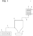
- FIG. 1 is a schematic diagram of a facility on a ship 1 equipped with a gas purification apparatus according to an embodiment.
- the ship 1 includes an engine 2 for generating a propelling force of the ship 1, and a gas purification apparatus 4 for removing sulfur oxide (SOx) from exhaust gas (gas) of the engine 2.
- the exhaust gas from the engine 2 is introduced into the gas purification apparatus 4 via the first connection pipe 3.
- the gas purification apparatus 4 will be described later in detail.
- the gas purification apparatus 4 depicted in FIG. 1 is configured to remove impure substances such as soot dust and oil as well as sulfur oxide contained in the exhaust gas.
- the impure substances separated from the exhaust gas by the gas purification apparatus 4 is discharged from the gas purification apparatus 4, and stored in a storage part 5. Furthermore, clean exhaust gas after being processed by the gas purification apparatus 4 is discharged to the outside (e.g. atmosphere) via the second connection pipe 6.
- the first connection pipe 3 or the second connection pipe 6 may include an exhaust gas processing apparatus other than the gas purification apparatus 4 (e.g. denitration apparatus or CO2 absorption apparatus) or an apparatus that utilizes exhaust gas.
- the second connection pipe 6 may include an economizer 8 for recovering heat from exhaust gas.
- the gas purification apparatus 4 may be configured to remove sulfur oxide from exhaust gas from the engine, as depicted in FIG. 1 . Furthermore, the gas purification apparatus according to some embodiments may be configured to remove nitrogen oxide from exhaust gas from the engine. Alternatively, the gas purification apparatus according to some embodiments may be configured to remove sulfur oxide or nitrogen oxide from exhaust gas from a combustion facility other than the engine (e.g. boiler or incinerator).
- a combustion facility e.g. boiler or incinerator
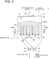
- FIGs. 2 to 4 are each a schematic diagram of a gas purification apparatus 4 according to an embodiment.
- the gas purification apparatus 4 includes a housing 10, and a filter portion 20 disposed inside the housing 10.
- the filter portion 20 is configured to remove impure substances in exhaust gas such as soot dust and oil.
- an inlet duct 12 and an outlet duct 14 are connected to the housing 10.
- the housing 10 is configured such that exhaust gas from the engine 2 (see FIG. 1 ) is introduced in to the housing 10 via the inlet duct 12.
- the exhaust gas introduced from the inlet duct 12 flows through the internal space of the housing 10, and then is discharged to the outside via the outlet duct 14.
- the inlet duct 12 may constitute a part of the first connection pipe 3 (see FIG. 1 ), and the outlet duct 14 may constitute a part of the second connection pipe 6.
- the internal space of the housing 10 is divided by the filter portion 20 into a space 16 at the upstream side of the filter portion 20 with respect to a flow of exhaust gas (hereinafter, also referred to as merely “upstream space”), and a space 18 at the downstream side of the filter portion 20 with respect to the flow of exhaust gas (hereinafter, referred to as merely “downstream space”).
- a desulfurization agent 9 (9a, 9b) gas purification agent for removing sulfur oxide in exhaust gas is disposed in the downstream space 18.
- a downstream separation device 38 is disposed at the downstream side of the filter portion 20 with respect to the flow of exhaust gas.
- the downstream separation device 38 is disposed between the housing 10 and the outlet duct 14, or on a connection portion between the housing 10 and the outlet duct 14.
- the downstream separation device 38 is configured to let through a gas, but not the desulfurization agent 9.
- the downstream separation device 38 may include a filter or a dust collector, for instance.
- the housing 10 includes, above the filter portion 20, a desulfurization agent supply pipe 30 and a supply valve 32 for supplying the desulfurization agent 9 into the housing.
- the housing 10 includes, below the filter portion 20, a discharge pipe 34 and a discharge valve 36 for discharging impure substances such as soot dust and oil separated from the exhaust gas by the filter portion 20. Furthermore, while the discharge valve 36 is configured to open when discharging impure substances such as soot dust and oil separated by the filter portion 20 outside the apparatus, the discharge valve 36 is normally closed so that exhaust gas flowing into the housing 10 does not leak out from the discharge pipe 34.
- the filter portion 20 includes a filter element 24 for removing impure substances such as soot dust and oil in the exhaust gas, and a support plate 22 (support portion) for supporting the filter element 24.
- the filter element 24 has a hollow portion 25, and is disposed so as to protrude from the downstream space 18 toward the upstream space 16. Further, the desulfurization agent 9a is disposed in the hollow portion 25 of the filter element 24.
- the filter element 24 has a tubular shape. Furthermore, the support plate 22 is disposed so as to spread along the horizontal direction, and has an opening 23 that has substantially the same diameter as the tubular shape of the filter element 24. The upper end portion of the filter element 24 having a tubular shape is attached to the opening 23 of the support plate 22. The filter element 24 extends downward from the support plate 22.
- the filter portion 20 may have the support plate 22 having a plurality of openings 23, and a plurality of filter elements 24.
- the support plate 22 is configured to store the backup desulfurization agent 9b above the desulfurization agent 9a disposed in the hollow portion 25 of the filter element 24.
- the filter element 24 is characterized in that the material and coarseness of the filter element 24 are configured so as to let a gas through but block impure substances such as soot dust and oil contained in exhaust gas.
- the filter element 24 may be formed by using a fiber product such as fabric (e.g. fabric filter) or formed by using porous ceramics (ceramics filter).
- a fiber product such as fabric (e.g. fabric filter) or formed by using porous ceramics (ceramics filter).
- the desulfurization agent 9 may be powder or particulate matter.
- slaked lime calcium hydroxide; Ca (OH)2
- activated coal or sodium bicarbonate (Na 2 HCO 3 )
- sodium bicarbonate Na 2 HCO 3
- the desulfurization agent 9 may be disposed on the outer surface or the inner surface of the filter element 24.
- a desulfurization agent may be mixed into a material (e.g. fiber product), or the desulfurization agent 9 may be supported on the surface (outer surface or inner surface) of the filter element 24 formed from a material by a methodology such as impregnation.
- exhaust gas is introduced into the housing 10 via the inlet duct 12. Accordingly, exhaust gas passes through the filter element 24 of the filter portion 20 from the upstream space 16, and then flows into the hollow portion 25 of the filter element 24 (downstream space 18).
- impure substances such as soot dust and oil contained in the exhaust gas are not able to pass through the filter element 24, and thereby impure substances such as soot dust and oil are removed from exhaust gas.
- the impure substances removed from the exhaust gas are collected on the upstream surface of the filter element 24, and accumulate with time.
- the desulfurization agent 9a disposed in the hollow portion 25 and exhaust gas make contact, and the sulfur oxide contained in exhaust gas is removed from exhaust gas due to reaction with the desulfurization agent 9a.
- impure substances such as soot dust and oil and sulfur oxide are removed from the exhaust gas, and the clean exhaust gas flows into the outlet duct 14.
- the clean exhaust gas passes through the downstream separation device 38 disposed at the downstream side of the filter portion 20.
- the desulfurization agent 9 accompanying the flow of exhaust gas flowing toward the outlet duct 14 from the downstream space 18 is removed.
- the clean exhaust gas after passing through the downstream separation device 38 is discharged outside the housing 10 via the outlet duct 14.
- impure substances such as soot dust and oil collected and accumulated on the upstream surface of the filter element 24 may be detached from the surface of the filter element 24 by operating the filter cleaning portion 50 (see FIGs. 5 and 6 , for instance) described below, for instance. Furthermore, the impure substances may be discharged outside the gas purification apparatus 4 from the discharge pipe 34 disposed below the filter portion 20.
- the consumed and used desulfurization agent 9 may be discharged from the hollow portion 25 of the filter element 24 via the discharge port 27 (see FIGs. 3 and 4 ) described below, for instance.
- both the filter portion 20 for removing impure substances (e.g. soot dust) in exhaust gas and the desulfurization agent 9 (gas purification agent) for removing sulfur oxide in exhaust gas are provided in the single housing 10, and thus it is possible to make the gas purification apparatus 4 more compact.
- the desulfurization agent 9 is disposed in the downstream space 18 of the filter portion 20 inside the housing 10, and thus it is possible to bring into contact the exhaust gas from which impure substances (e.g. soot dust) are removed and the desulfurization agent 9. Accordingly, it is possible to suppress deterioration of the reaction rate due to contamination of the desulfurization agent 9 with impure substances.
- the gas purification apparatus 4 it is possible to make the apparatus compact while improving the efficiency of desulfurization (gas purification). Furthermore, with the gas purification apparatus 4 according to the above embodiment, the exhaust gas after removing impure substances with the filter portion 20 is brought into contact with the desulfurization agent 9, and thus it is possible to retrieve the used desulfurization agent and impure substances separated from exhaust gas by the filter portion 20 separately. Thus, it is possible to facilitate reutilization of the used desulfurization agent (gas purification agent) (e.g. regeneration of the desulfurization agent, or reuse as a material in another industry).
- gas purification agent gas purification agent
- the filter element 24 may include a discharge port 27 for discharging the desulfurization agent 9 from the hollow portion 25 of the filter element 24. Furthermore, the filter element 24 may have an opening-and-closing portion 26 configured to open and close the discharge port 27.
- the discharge port 27 is disposed on the lower end portion of the filter element 24 extending in the up-down direction in a tubular shape, and the opening-and-closing portion 26 capable of opening and closing the discharge port 27 is provided.
- the opening-and-closing portion 26 may include a rotary valve, for instance.
- the desulfurization agent 9 inside the hollow portion 25 falls under its own weight. Accordingly, it is possible to improve the desulfurization performance of the desulfurization agent 9, and discharge the desulfurization agent 9 from the hollow portion 25 even more easily.
- the backup desulfurization agent 9 is disposed above the hollow portion 25, when the desulfurization agent disposed in the hollow portion 25 of the filter element 24 is consumed and used, it is possible to easily replace the used desulfurization agent with the desulfurization agent 9b disposed above, by discharging the used desulfurization agent from the hollow portion 25 via the discharge port 27. Thus, it is possible to operate the gas purification apparatus 4 more efficiently.
- the opening-and-closing portion 26 capable of opening and closing the discharge port 27 as in the above described embodiment, it is possible to discharge the desulfurization agent 9 from the hollow portion 25 at a desired timing. For instance, by opening the opening-and-closing portion 26 at the timing when the desulfurization agent 9 disposed in the hollow portion 25 is used up, it is possible to discharge only the used desulfurization agent 9 from the hollow portion 25. Thus, it is possible to operate the gas purification apparatus 4 more efficiently.
- the used desulfurization agent after completing reaction with the sulfur oxide is calcium sulfite (CaSO 3 ) or calcium sulfate (CaSO 4 ).
- the gas purification apparatus 4 includes a discharge chamber 42 for discharging the desulfurization agent 9 from the hollow portion 25, and the discharge chamber 42 is separated from the upstream space 16.
- the discharge chamber 42 and the upstream space 16 are separated by a separation plate 40 that extends in the horizontal direction in the vicinity of the lower end portion of the filter element 24 extending in the up-down direction.
- the discharge chamber 42 may be formed at least partially by the housing 10.
- a discharge pipe 44 for discharging the used desulfurization agent 9 to the outside of the gas purification apparatus 4 and a discharge valve 46 for switching the discharge state of the used desulfurization agent 9 from the discharge pipe 44 are provided below the discharge chamber 42.
- FIG. 5 is a schematic configuration diagram of a filter element 24 and a filter cleaning portion 50 according to an embodiment.
- FIG. 6 is a schematic cross-sectional diagram of the filter element 24 and the filter cleaning portion 50 depicted in FIG. 5 .
- the gas purification apparatus 4 may further include a filter cleaning portion 50 configured to blow a fluid (e.g. a gas like air) toward the filter element 24.
- a fluid e.g. a gas like air
- the filter cleaning portion 50 may be configured to blow a fluid toward the filter element 24 from the outer side of the filter element 24, or may be configured to blow a fluid toward the filter element 24 from the inside of the filter element 24 (e.g. from the hollow portion of the filter element 24).
- the filter cleaning portion 50 includes a gas injection portion 52 (fluid injection portion) disposed at the outer side of the desulfurization agent 9 in the hollow portion 25 of the filter element 24, and a gas supply portion 54 (e.g. tube) for supplying a gas toward the gas injection portion 52.
- a gas injection portion 52 fluid injection portion
- a gas supply portion 54 e.g. tube
- the gas injection portion 52 may be a porous sheet.
- the gas injection portion 52 may be a tube that extends along the longitudinal direction or the circumferential direction of the filter element 24 and that has gas injection holes.
- the gas injection portion 52 may inject a gas toward the inside of the filter element 24, or toward the outside of the filter element 24.
- the filter cleaning portion 50 capable of blowing a gas toward the filter element 24, it is possible to blow off impure substances such as soot dust and oil adhering to the filter element 24, and remove the the impure substances from the filter element 24.
- impure substances such as soot dust and oil adhering to the filter element 24
- a pre-coating portion that covers the filter element 24 may be provided.
- the pre-coating portion may be formed by blowing a soot removal agent or an oil removal agent (e.g. talc) on the upstream surface of the filter element 24.
- a soot removal agent or an oil removal agent e.g. talc
- the gas purification apparatus 4 further includes a denitration catalyst supported by the filter element 24 of the filter portion 20.
- the filter element 24 may by produced by using a fabric woven with fibers mixed with a denitration catalyst, or by impregnating a fabric with a liquid containing a denitration catalyst and drying the liquid.
- a microporous ceramics filter supporting a catalyst may be used as the filter element 24.
- the filter element 24 supporting the denitration catalyst it is possible to remove nitrogen oxide in the exhaust gas when the exhaust gas passes through the filter element 24.
- the facility including the gas purification apparatus 4 it is possible to make the facility including the gas purification apparatus 4 more compact.
- the desulfurization agent 9 contains slaked lime (calcium hydroxide; Ca (OH)2).
- calcium hydroxide (slaked lime) has an effect to remove CO2 in a gas as well as a desulfurization effect, and thus it is possible to remove CO 2 at the same time in addition to sulfur oxide contained in the exhaust gas.
- the facility including the gas purification apparatus 4 it is possible to make the facility including the gas purification apparatus 4 more compact.
- the gas purification apparatus 4 may be configured to remove nitrogen oxide and/or carbon dioxide from exhaust gas from the engine.
- a nitrogen-oxide removal agent and/or a carbon-dioxide removal agent may be used instead of the above described desulfurization agent 9, or a nitrogen-oxide removal agent and/or a carbon-dioxide removal agent may be used together with the desulfurization agent 9.
- an expression of relative or absolute arrangement such as “in a direction”, “along a direction”, “parallel”, “orthogonal”, “centered”, “concentric” and “coaxial” shall not be construed as indicating only the arrangement in a strict literal sense, but also includes a state where the arrangement is relatively displaced by a tolerance, or by an angle or a distance whereby it is possible to achieve the same function.
- an expression of an equal state such as “same” “equal” and “uniform” shall not be construed as indicating only the state in which the feature is strictly equal, but also includes a state in which there is a tolerance or a difference that can still achieve the same function.
- an expression of a shape such as a rectangular shape or a cylindrical shape shall not be construed as only the geometrically strict shape, but also includes a shape with unevenness or chamfered corners within the range in which the same effect can be achieved.
Landscapes
- Engineering & Computer Science (AREA)
- Chemical & Material Sciences (AREA)
- Chemical Kinetics & Catalysis (AREA)
- Combustion & Propulsion (AREA)
- Environmental & Geological Engineering (AREA)
- Mechanical Engineering (AREA)
- Analytical Chemistry (AREA)
- General Chemical & Material Sciences (AREA)
- Health & Medical Sciences (AREA)
- Biomedical Technology (AREA)
- General Engineering & Computer Science (AREA)
- Oil, Petroleum & Natural Gas (AREA)
- Geometry (AREA)
- Physics & Mathematics (AREA)
- Materials Engineering (AREA)
- Organic Chemistry (AREA)
- Ocean & Marine Engineering (AREA)
- Treating Waste Gases (AREA)
- Exhaust Gas After Treatment (AREA)
- Processes For Solid Components From Exhaust (AREA)
- Filtering Of Dispersed Particles In Gases (AREA)
- Exhaust Gas Treatment By Means Of Catalyst (AREA)
- Catalysts (AREA)
Abstract
Description
- The present disclosure relates to a gas purification apparatus, a ship including the same, and a gas purification method.
- As a gas purification apparatus for removing sulfur oxide (SOx), nitrogen oxide (NOx), or carbon dioxide (CO2) contained in exhaust gas from a combustion facility or the like of an engine or the like, a dry-type gas purification apparatus using a solid gas purification agent may be used.
- For instance,
Patent Document 1 discloses a dry-type desulfurization apparatus for removing sulfur oxide or the like from exhaust gas from a furnace. The dry-type desulfurization apparatus is configured to inject a desulfurization agent (slaked lime or activated coal) into a connection duct for introducing exhaust gas from the furnace into a housing, and cause the desulfurization agent to contact and make reaction with sulfur oxide in the exhaust gas, thereby removing sulfur oxide from the exhaust gas. A filter is disposed inside the housing of the dry-type desulfurization apparatus, and the desulfurization agent after reaction is collected by the filter along with soot dust in the exhaust gas. Furthermore, exhaust gas after passing the filter is discharged to the atmosphere via a stack after necessary post-treatment. - Patent Document 1:
JP3057878U - The gas purification apparatus (desulfurization apparatus) in
Patent Document 1 is configured to collect, by using the filter, the gas purification agent (desulfurization agent) after performing a purification process (desulfurization process) of exhaust gas and impure substances (soot dust, etc.) in exhaust gas, at the same time. Thus, for instance, when the used gas purification agent is to be reused with minimum contamination from impure substances such as soot dust, the size of the apparatus can be reduced compared to a case where exhaust gas after removing dust with a filter is introduced to another housing for a gas purification process. - On the other hand, the gas purification apparatus in
Patent Document 1 is configured to inject a gas purification agent into exhaust gas that contains soot dust or the like, and thus the soot dust or the like may adhere to the surface of the gas purification agent injected into the exhaust gas. Accordingly, the gas purification agent may be covered by the soot dust or the like within the exhaust gas, which may reduce the opportunity of contact between the removal target substance (sulfur oxide) in the exhaust gas and the gas purification agent, and deteriorate the reaction rate of the gas purification reaction. Furthermore, the gas purification agent collected by the filter is mixed with the impure substances such as soot dust, and thus reutilization of the gas purification agent is not easy. Furthermore, if dust removal and gas purification are carried out in separate housings, the size increase of the apparatus would be inevitable. - In view of the above, an object of at least one embodiment of the present invention is to provide a gas purification apparatus, a ship including the same, and a gas purification method, capable of making the apparatus compact while improving the efficiency of gas purification.
- (1) According to at least one embodiment of the present invention, a gas purification apparatus includes: a housing to which a gas is introduced; a filter portion for removing an impure substance in the gas from the gas, the filter portion being disposed inside the housing; and a gas purification agent for removing a removal target substance in the gas from the gas, the gas purification agent being disposed, inside the housing, on the filter potion or in a space at a downstream side of the filter portion with respect to a flow of the gas.
- With the above configuration (1), both the filter portion for removing impure substances (e.g. soot dust or oil) in the gas and the gas purification agent for removing a removal target substance (e.g., sulfur oxide, nitrogen oxide, or carbon dioxide) in the gas are provided in the single housing, and thus it is possible to make the gas purification apparatus more compact. Furthermore, with the above configuration (1), the gas purification agent is disposed, inside the housing, in the downstream space of the filter portion or on the filter portion, and thus it is possible to bring into contact the gas purification agent and the gas from which impure substances are removed after passing the filter. Accordingly, it is possible to suppress deterioration of the reaction rate due to contamination of the gas purification agent with impure substances. Thus, with the above configuration (1), it is possible to make the apparatus compact, and improve the efficiency of gas purification at the same time.
- Furthermore, with the gas purification apparatus in
Patent Document 1, the gas purification agent after reaction is collected by the filter with the impure substances in the gas, and thus the used gas purification agent is retrieved from the apparatus as a mixture with impure substances. In this regard, with the above configuration (1), the gas after removing impure substances or the like with the filter portion is brought into contact with the gas purification agent, and thus it is possible to retrieve the used gas purification agent and impure substances separated from the gas by the filter portion separately. Thus, it is possible to facilitate reutilization of a used gas purification agent. - Furthermore, the gas purification agent disposed in the downstream space of the filter portion includes the gas purification agent disposed in the hollow portion of the filter element described below, for instance. Furthermore, the gas purification agent disposed on the filter portion includes the gas purification agent supported by the filter element described below.
- (2) In some embodiments, in the above configuration (1), the filter portion includes a filter element having a hollow portion, the filter element being disposed so as to protrude from the space at the downstream side toward a space at an upstream side of the filter portion with respect to the flow of the gas, and the gas purification agent is disposed at least in the filter element or in the hollow portion of the filter element.
- With the above configuration (2), the filter element is disposed so as to protrude from the downstream space toward the upstream space of the filter portion, and thus it is possible to remove impure substances reliably from the gas flowing into the hollow portion via the filter element from the upstream space. Furthermore, since the gas purification agent is disposed in the hollow portion of the filter element or in the filter element (e.g. the outer surface of the inner surface of the filter element), it is possible to save the space, and further reduce the size of the gas purification apparatus.
- (3) In some embodiments, in the above configuration (2), the filter element includes a tubular filter element.
- With the above configuration (3), a tubular filter element is used, and thus it is possible to provide a relatively large number of filter elements inside the housing with a limited space, and improve the gas purification efficiency even further. Furthermore, the filter element has a simple tubular shape, and thus can be produced relatively easily.
- (4) In some embodiments, in the above configuration (2) or (3), the filter portion further includes a support portion for supporting the filter element, the filter element protrudes downward from the support portion, and the support portion is configured to store a backup gas purification agent above the gas purification agent.
- With the above configuration (4), a backup gas purification agent can be stored above the gas purification agent disposed in the hollow portion of the filter element or in the filter element protruding downward from the support portion, and thus the gas flowing into the hollow portion from the upstream space of the filter element can flow above and make contact with the backup gas purification agent. Thus, it is possible to perform a gas purification processing on the gas more effectively. Furthermore, with the above configuration (4), when the gas purification agent disposed in the hollow portion of the filter element is consumed and used, the gas purification agent disposed above can be supplied to the hollow portion by discharging the used gas purification from the hollow portion, and thus it is possible to operate the gas purification apparatus more efficiently.
- (5) In some embodiments, in any one of the above configurations (2) to (4), the gas purification apparatus further includes a discharge port for discharging the gas purification agent from the hollow portion of the filter element, the discharge port being disposed on the filter element.
- With the above configuration (5), it is possible to discharge the gas purification agent from the hollow portion via the discharge port disposed in the filter element, and thus it is possible to discharge the gas purification agent via the discharge port easily. Furthermore, it is possible to supply and replace the gas purification agent easily.
- (6) In some embodiments, in the above configuration (5), the gas purification apparatus further includes an opening-and-closing portion configured to open and close the discharge port.
- With the above configuration (6), by providing the opening-and-closing portion capable of opening and closing the discharge port, it is possible to discharge the gas purification agent from the hollow portion at a desired timing. For instance, by opening the opening-and-closing portion at the timing when the gas purification agent disposed in the hollow portion is used up, it is possible to discharge the gas purification agent from the hollow portion. Thus, it is possible to operate the gas purification apparatus more efficiently.
- (7) In some embodiments, in the above configuration (5) or (6), the gas purification apparatus further includes a discharge chamber through which the gas purification agent is to be discharged from the hollow portion, and the discharge chamber and the space at the upstream side are separated.
- With the above configuration (7), by separating the upstream space where impure substances separated from the exhaust gas at the filter portion remain and the discharge chamber being a space through which the used gas purification agent is discharged from the hollow portion, it is possible to suppress contamination of the discharged gas purification agent with impure substances or the like. Therefore, it is possible to retrieve the used gas purification agent in a relatively high purity, and thus it is possible to reuse the used gas purification agent.
- (8) In some embodiments, in any one of the above configurations (2) to (7), the gas purification apparatus further includes a filter cleaning portion configured to blow a fluid toward the filter element, or a pre-coating portion covering the filter element.
- With the above configuration (8), with the filter cleaning portion capable of blowing a fluid (e.g. cleaning gas) toward the filter element, it is possible to blow off impure substances adhering to the filter element. Thus, it is possible to suppress adherence of impure substances to the filter element and reduce pressure loss, thereby performing gas purification more efficiently.
- Alternatively, with the above configuration (8), a pre-coating portion that covers the filter element is provided, and thus it is possible to suppress clogging and adherence of impure substances to the filter element effectively, and carry out gas purification efficiently.
- (9) In some embodiments, in the above configuration (8), the gas purification apparatus includes the filter cleaning portion, and the filter cleaning portion includes a gas injection portion disposed outside the gas purification agent inside the hollow portion.
- With the above configuration (9), the fluid injection portion is disposed outside the gas purification agent in the hollow portion of the filter element, and thus it is possible to blow off impure substances adhering to the filter element effectively.
- (10) In some embodiments, in any one of the above configurations (1) to (9), the gas purification apparatus further includes a downstream separation device for removing the gas purification agent accompanying the flow of the gas discharged outside the housing from the space at the downstream side, the downstream separation device being disposed at a downstream side of the filter portion with respect to the flow of the gas.
- In the gas purification apparatus having the above configuration (1), the gas purification agent is disposed at the downstream side of the filter portion, and thus the gas purification agent may accompany the gas flow at the downstream side of the filter portion.
- In this regard, with the above configuration (10), the downstream separation device is disposed at the downstream side of the filter portion, and thus it is possible to suppress an outflow of the gas purification agent accompanying the gas flow after passing the filter portion. Thus, it is possible to reduce loss of the gas purification agent.
- (11) In some embodiments, in any one of the above configurations (1) to (10), the gas purification agent contains calcium hydroxide.
- Calcium hydroxide (slaked lime) has an effect to remove CO2 in a gas as well as a desulfurization effect.
- With the above configuration (11), calcium hydroxide is used as the gas purification agent, and thus it is possible to remove CO2 at the same time in addition to sulfur oxide contained in the gas, and thus it is possible to make the facility including the gas purification apparatus more compact.
- (12) In some embodiments, in any one of the above configurations (1) to (11), the gas purification apparatus further includes a denitration catalyst supported by a filter element of the filter portion.
- With the above configuration (12), the filter element supports the denitration catalyst, and thus it is possible to remove nitrogen oxide in the gas when the gas passes through the filter element. Thus, it is possible to make the facility including the gas purification apparatus more compact.
- (13) According to at least one embodiment of the present invention, a ship includes: an engine; and the gas purification apparatus according to any one of the above (1) to (12), and the gas purification apparatus is configured such that exhaust gas from the engine is introduced into the housing of the gas purification apparatus as the gas.
- With the above configuration (13), both the filter portion for removing impure substances in the gas and the gas purification agent for removing a removal target substance (sulfur oxide, nitrogen oxide, or carbon dioxide) in the gas are provided in the single housing, and thus it is possible to make the gas purification apparatus more compact. Furthermore, with the above configuration (13), the gas purification agent is disposed, inside the housing, in the downstream space of the filter portion or on the filter portion, and thus it is possible to bring into contact between the gas from which impure substances are removed after passing the filter and the gas purification agent. Accordingly, it is possible to suppress deterioration of the reaction rate due to contamination of the gas purification agent with impure substances. Thus, with the above configuration (13), it is possible to make the apparatus compact, and improve the efficiency of gas purification at the same time.
- Furthermore, with the above configuration (13), the gas after removing impure substances or the like with the filter portion is brought into contact with the gas purification agent. Thus, it is possible to retrieve impure substances separated from the gas by the filter portion and the used gas purification agent separately. Thus, it is possible to facilitate reutilization of a used gas purification agent.
- (14) According to at least one embodiment of the present invention, a method of purifying a gas includes: a step of introducing a gas into a housing; a step of removing impure substances in the gas from the gas with a filter portion disposed inside the housing; and a step of removing a removal target substance in the gas from the gas with a gas purification agent disposed, inside the housing, on the filter portion or in a space at a downstream side of the filter portion with respect to a flow of the gas.
- According to the above method (14), both the filter portion for removing impure substances in the gas and the gas purification agent for removing a removal target substance (e.g. sulfur oxide, nitrogen oxide, or carbon dioxide) in the gas are provided in the single housing, and thus it is possible to make the apparatus for performing the gas purification method more compact. Furthermore, with the above method (14), the gas purification agent is disposed, inside the housing, in the downstream space of the filter portion or on the filter portion, and thus it is possible to bring the gas from which impure substances are removed after passing the filter into contact with the gas purification agent. Accordingly, it is possible to suppress deterioration of the reaction rate due to contamination of the gas purification agent with impure substances. Thus, with the above method (14), it is possible to make the apparatus compact, and improve the efficiency of gas purification at the same time.
- Furthermore, according to the above method (14), the gas after removing impure substances or the like with the filter portion is brought into contact with the gas purification agent, and thus it is possible to retrieve impure substances separated from the gas by the filter portion and the used gas purification agent separately. Thus, it is possible to facilitate reutilization of a used gas purification agent.
- (15) In some embodiments, the above method (14) further includes a step of removing the gas purification agent accompanying the flow of the gas discharged outside the housing from the space at the downstream side, with a downstream separation device disposed at a downstream side of the filter portion with respect to the flow of the gas.
- In the gas purification method (14), the gas purification agent is disposed at the downstream side of the filter portion, and thus the gas purification agent may accompany the gas flow at the downstream side of the filter portion.
- In this regard, with the above configuration (15), the downstream separation device is disposed at the downstream side of the filter portion, and thus it is possible to suppress an outflow of the gas purification agent accompanying the gas flow after passing the filter portion. Thus, it is possible to reduce loss of the gas purification agent.
- According to at least one embodiment of the present invention, it is possible to provide a gas purification apparatus, a ship including the same, and a gas purification method, capable of making the apparatus compact while improving the efficiency of gas purification.
-
-
FIG. 1 is a schematic diagram of a facility on a ship equipped with a gas purification apparatus according to an embodiment. -
FIG. 2 is a schematic diagram of a gas purification apparatus according to an embodiment. -
FIG. 3 is a schematic diagram of a gas purification apparatus according to an embodiment. -
FIG. 4 is a schematic diagram of a gas purification apparatus according to an embodiment. -
FIG. 5 is a schematic configuration diagram of a filter element and a filter cleaning portion according to an embodiment. -
FIG. 6 is a schematic cross-sectional diagram of the filter element and the filter cleaning portion depicted inFIG. 5 . - Embodiments of the present invention will now be described in detail with reference to the accompanying drawings. It is intended, however, that unless particularly identified, dimensions, materials, shapes, relative positions and the like of components described in the embodiments shall be interpreted as illustrative only and not intended to limit the scope of the present invention.
-
FIG. 1 is a schematic diagram of a facility on aship 1 equipped with a gas purification apparatus according to an embodiment. As depicted inFIG. 1 , theship 1 includes anengine 2 for generating a propelling force of theship 1, and agas purification apparatus 4 for removing sulfur oxide (SOx) from exhaust gas (gas) of theengine 2. The exhaust gas from theengine 2 is introduced into thegas purification apparatus 4 via thefirst connection pipe 3. Thegas purification apparatus 4 will be described later in detail. Thegas purification apparatus 4 depicted inFIG. 1 is configured to remove impure substances such as soot dust and oil as well as sulfur oxide contained in the exhaust gas. The impure substances separated from the exhaust gas by thegas purification apparatus 4 is discharged from thegas purification apparatus 4, and stored in astorage part 5. Furthermore, clean exhaust gas after being processed by thegas purification apparatus 4 is discharged to the outside (e.g. atmosphere) via thesecond connection pipe 6. - The
first connection pipe 3 or thesecond connection pipe 6 may include an exhaust gas processing apparatus other than the gas purification apparatus 4 (e.g. denitration apparatus or CO2 absorption apparatus) or an apparatus that utilizes exhaust gas. For instance, as depicted inFIG. 1 , thesecond connection pipe 6 may include aneconomizer 8 for recovering heat from exhaust gas. - Next, the
gas purification apparatus 4 according to some embodiments will be described in more detail. Thegas purification apparatus 4 according to some embodiments may be configured to remove sulfur oxide from exhaust gas from the engine, as depicted inFIG. 1 . Furthermore, the gas purification apparatus according to some embodiments may be configured to remove nitrogen oxide from exhaust gas from the engine. Alternatively, the gas purification apparatus according to some embodiments may be configured to remove sulfur oxide or nitrogen oxide from exhaust gas from a combustion facility other than the engine (e.g. boiler or incinerator). -
FIGs. 2 to 4 are each a schematic diagram of agas purification apparatus 4 according to an embodiment. As depicted inFIGs. 2 to 4 , thegas purification apparatus 4 includes ahousing 10, and afilter portion 20 disposed inside thehousing 10. Thefilter portion 20 is configured to remove impure substances in exhaust gas such as soot dust and oil. Furthermore, aninlet duct 12 and anoutlet duct 14 are connected to thehousing 10. - The
housing 10 is configured such that exhaust gas from the engine 2 (seeFIG. 1 ) is introduced in to thehousing 10 via theinlet duct 12. The exhaust gas introduced from theinlet duct 12 flows through the internal space of thehousing 10, and then is discharged to the outside via theoutlet duct 14. Theinlet duct 12 may constitute a part of the first connection pipe 3 (seeFIG. 1 ), and theoutlet duct 14 may constitute a part of thesecond connection pipe 6. - The internal space of the
housing 10 is divided by thefilter portion 20 into aspace 16 at the upstream side of thefilter portion 20 with respect to a flow of exhaust gas (hereinafter, also referred to as merely "upstream space"), and aspace 18 at the downstream side of thefilter portion 20 with respect to the flow of exhaust gas (hereinafter, referred to as merely "downstream space"). In thedownstream space 18, a desulfurization agent 9 (9a, 9b) (gas purification agent) for removing sulfur oxide in exhaust gas is disposed. - A
downstream separation device 38 is disposed at the downstream side of thefilter portion 20 with respect to the flow of exhaust gas. In the illustrative embodiment depicted inFIGs. 2 to 4 , thedownstream separation device 38 is disposed between thehousing 10 and theoutlet duct 14, or on a connection portion between thehousing 10 and theoutlet duct 14. Furthermore, thedownstream separation device 38 is configured to let through a gas, but not thedesulfurization agent 9. Thedownstream separation device 38 may include a filter or a dust collector, for instance. - The
housing 10 includes, above thefilter portion 20, a desulfurizationagent supply pipe 30 and asupply valve 32 for supplying thedesulfurization agent 9 into the housing. - Furthermore, the
housing 10 includes, below thefilter portion 20, adischarge pipe 34 and adischarge valve 36 for discharging impure substances such as soot dust and oil separated from the exhaust gas by thefilter portion 20. Furthermore, while thedischarge valve 36 is configured to open when discharging impure substances such as soot dust and oil separated by thefilter portion 20 outside the apparatus, thedischarge valve 36 is normally closed so that exhaust gas flowing into thehousing 10 does not leak out from thedischarge pipe 34. - In some embodiments, the
filter portion 20 includes afilter element 24 for removing impure substances such as soot dust and oil in the exhaust gas, and a support plate 22 (support portion) for supporting thefilter element 24. Thefilter element 24 has ahollow portion 25, and is disposed so as to protrude from thedownstream space 18 toward theupstream space 16. Further, thedesulfurization agent 9a is disposed in thehollow portion 25 of thefilter element 24. - In the illustrative embodiment depicted in
FIGs. 2 to 4 , thefilter element 24 has a tubular shape. Furthermore, thesupport plate 22 is disposed so as to spread along the horizontal direction, and has anopening 23 that has substantially the same diameter as the tubular shape of thefilter element 24. The upper end portion of thefilter element 24 having a tubular shape is attached to theopening 23 of thesupport plate 22. Thefilter element 24 extends downward from thesupport plate 22. Thefilter portion 20 may have thesupport plate 22 having a plurality ofopenings 23, and a plurality offilter elements 24. - As depicted in
FIGs. 2 to 4 , thesupport plate 22 is configured to store thebackup desulfurization agent 9b above thedesulfurization agent 9a disposed in thehollow portion 25 of thefilter element 24. - The
filter element 24 is characterized in that the material and coarseness of thefilter element 24 are configured so as to let a gas through but block impure substances such as soot dust and oil contained in exhaust gas. - The
filter element 24 may be formed by using a fiber product such as fabric (e.g. fabric filter) or formed by using porous ceramics (ceramics filter). - The
desulfurization agent 9 may be powder or particulate matter. - As the
desulfurization agent 9, for instance, slaked lime (calcium hydroxide; Ca (OH)2), activated coal, or sodium bicarbonate (Na2HCO3) may be used. - In a case where slaked lime is used, when the slaked lime makes contact with sulfur oxide (SOx) in exhaust gas, a chemical reaction occurs and produces calcium sulfite (CaSO3; solid), calcium sulfate (CaSO4; solid), and water (H2O). Furthermore, in a case where activated coal is used, when the activated coal makes contact with sulfur oxide (SOx) in exhaust gas, the sulfur oxide is adsorbed by the activated coal. Accordingly, through fixation of sulfur oxide in the exhaust gas to the desulfurization agent, sulfur oxide is removed from exhaust gas (desulfurization).
- Further, the
desulfurization agent 9 may be disposed on the outer surface or the inner surface of thefilter element 24. In this case, to be used as thefilter element 24, a desulfurization agent may be mixed into a material (e.g. fiber product), or thedesulfurization agent 9 may be supported on the surface (outer surface or inner surface) of thefilter element 24 formed from a material by a methodology such as impregnation. - Next, the procedure of desulfurization of exhaust gas from the engine 2 (see
FIG. 1 ) using thegas purification apparatus 4 having the above described configuration will be described. - First, exhaust gas is introduced into the
housing 10 via theinlet duct 12. Accordingly, exhaust gas passes through thefilter element 24 of thefilter portion 20 from theupstream space 16, and then flows into thehollow portion 25 of the filter element 24 (downstream space 18). - When the exhaust gas passes through the
filter element 24, impure substances such as soot dust and oil contained in the exhaust gas are not able to pass through thefilter element 24, and thereby impure substances such as soot dust and oil are removed from exhaust gas. The impure substances removed from the exhaust gas are collected on the upstream surface of thefilter element 24, and accumulate with time. - The exhaust gas from which impure substances have been removed by the
filter element 24 flows into thehollow portion 25 of thefilter element 24. In thehollow portion 25, thedesulfurization agent 9a disposed in thehollow portion 25 and exhaust gas make contact, and the sulfur oxide contained in exhaust gas is removed from exhaust gas due to reaction with thedesulfurization agent 9a. - Further, as depicted in
FIGs. 2 to 4 , in a case where thedesulfurization agent 9b is additionally stored above thedesulfurization agent 9a, exhaust gas flowing toward theoutlet duct 14 from thehollow portion 25 also makes contact with thedesulfurization agent 9b. Thus, it is possible to improve the desulfurization performance of thegas purification apparatus 4, and remove sulfur oxide in the exhaust gas more reliably. - Accordingly, with the
filter element 24 and the desulfurization agents 9 (9a, 9b), impure substances such as soot dust and oil and sulfur oxide are removed from the exhaust gas, and the clean exhaust gas flows into theoutlet duct 14. At this time, the clean exhaust gas passes through thedownstream separation device 38 disposed at the downstream side of thefilter portion 20. At thedownstream separation device 38, thedesulfurization agent 9 accompanying the flow of exhaust gas flowing toward theoutlet duct 14 from thedownstream space 18 is removed. - The clean exhaust gas after passing through the
downstream separation device 38 is discharged outside thehousing 10 via theoutlet duct 14. - Furthermore, impure substances such as soot dust and oil collected and accumulated on the upstream surface of the
filter element 24 may be detached from the surface of thefilter element 24 by operating the filter cleaning portion 50 (seeFIGs. 5 and6 , for instance) described below, for instance. Furthermore, the impure substances may be discharged outside thegas purification apparatus 4 from thedischarge pipe 34 disposed below thefilter portion 20. - Furthermore, the consumed and used
desulfurization agent 9 may be discharged from thehollow portion 25 of thefilter element 24 via the discharge port 27 (seeFIGs. 3 and4 ) described below, for instance. - With the
gas purification apparatus 4 according to the above embodiment, both thefilter portion 20 for removing impure substances (e.g. soot dust) in exhaust gas and the desulfurization agent 9 (gas purification agent) for removing sulfur oxide in exhaust gas are provided in thesingle housing 10, and thus it is possible to make thegas purification apparatus 4 more compact. Furthermore, with thegas purification apparatus 4 according to the above described embodiment, thedesulfurization agent 9 is disposed in thedownstream space 18 of thefilter portion 20 inside thehousing 10, and thus it is possible to bring into contact the exhaust gas from which impure substances (e.g. soot dust) are removed and thedesulfurization agent 9. Accordingly, it is possible to suppress deterioration of the reaction rate due to contamination of thedesulfurization agent 9 with impure substances. Thus, with thegas purification apparatus 4 according to the above embodiment, it is possible to make the apparatus compact while improving the efficiency of desulfurization (gas purification). Furthermore, with thegas purification apparatus 4 according to the above embodiment, the exhaust gas after removing impure substances with thefilter portion 20 is brought into contact with thedesulfurization agent 9, and thus it is possible to retrieve the used desulfurization agent and impure substances separated from exhaust gas by thefilter portion 20 separately. Thus, it is possible to facilitate reutilization of the used desulfurization agent (gas purification agent) (e.g. regeneration of the desulfurization agent, or reuse as a material in another industry). - In some embodiments, the
filter element 24 may include adischarge port 27 for discharging thedesulfurization agent 9 from thehollow portion 25 of thefilter element 24. Furthermore, thefilter element 24 may have an opening-and-closingportion 26 configured to open and close thedischarge port 27. - In the illustrative embodiment depicted in
FIGs. 3 and4 , thedischarge port 27 is disposed on the lower end portion of thefilter element 24 extending in the up-down direction in a tubular shape, and the opening-and-closingportion 26 capable of opening and closing thedischarge port 27 is provided. The opening-and-closingportion 26 may include a rotary valve, for instance. - As described above, it is possible to discharge the
desulfurization agent 9 from thehollow portion 25 via thedischarge port 27 disposed in thefilter element 24, and thus it is possible to discharge thedesulfurization agent 9 easily via thedischarge port 27. Furthermore, it is possible to supply and replace thedesulfurization agent 9 easily. - Furthermore, with the
discharge port 27 being disposed on the lower end portion of thefilter element 24, thedesulfurization agent 9 inside thehollow portion 25 falls under its own weight. Accordingly, it is possible to improve the desulfurization performance of thedesulfurization agent 9, and discharge thedesulfurization agent 9 from thehollow portion 25 even more easily. - Furthermore, in a case where the
backup desulfurization agent 9 is disposed above thehollow portion 25, when the desulfurization agent disposed in thehollow portion 25 of thefilter element 24 is consumed and used, it is possible to easily replace the used desulfurization agent with thedesulfurization agent 9b disposed above, by discharging the used desulfurization agent from thehollow portion 25 via thedischarge port 27. Thus, it is possible to operate thegas purification apparatus 4 more efficiently. - Furthermore, by providing the opening-and-closing
portion 26 capable of opening and closing thedischarge port 27 as in the above described embodiment, it is possible to discharge thedesulfurization agent 9 from thehollow portion 25 at a desired timing. For instance, by opening the opening-and-closingportion 26 at the timing when thedesulfurization agent 9 disposed in thehollow portion 25 is used up, it is possible to discharge only the useddesulfurization agent 9 from thehollow portion 25. Thus, it is possible to operate thegas purification apparatus 4 more efficiently. - Furthermore, in a case where slaked lime (calcium hydroxide; Ca (OH)2) is used as the desulfurization agent, the used desulfurization agent after completing reaction with the sulfur oxide is calcium sulfite (CaSO3) or calcium sulfate (CaSO4).
- In some embodiments, as depicted in
FIG. 4 for instance, thegas purification apparatus 4 includes adischarge chamber 42 for discharging thedesulfurization agent 9 from thehollow portion 25, and thedischarge chamber 42 is separated from theupstream space 16. - In the embodiment depicted in
FIG. 4 , in the internal space of thehousing 10, thedischarge chamber 42 and theupstream space 16 are separated by aseparation plate 40 that extends in the horizontal direction in the vicinity of the lower end portion of thefilter element 24 extending in the up-down direction. - As depicted in
FIG. 4 , thedischarge chamber 42 may be formed at least partially by thehousing 10. - Furthermore, in the embodiment depicted in
FIG. 4 , below thedischarge chamber 42, adischarge pipe 44 for discharging the useddesulfurization agent 9 to the outside of thegas purification apparatus 4, and adischarge valve 46 for switching the discharge state of the useddesulfurization agent 9 from thedischarge pipe 44 are provided. - Accordingly, by separating the
upstream space 16 where impure substances such as soot dust and oil separated from the exhaust gas in thefilter portion 20 remain and thedischarge chamber 42 being a space through which the useddesulfurization agent 9 is discharged from thehollow portion 25, it is possible to suppress contamination of the dischargeddesulfurization agent 9 with impure substances such as soot dust and oil. Therefore, it is possible to retrieve the used desulfurization agent in a relatively high purity, and thus it is possible to reuse the used desulfurization agent. -
FIG. 5 is a schematic configuration diagram of afilter element 24 and afilter cleaning portion 50 according to an embodiment.FIG. 6 is a schematic cross-sectional diagram of thefilter element 24 and thefilter cleaning portion 50 depicted inFIG. 5 . - In some embodiments, the gas purification apparatus 4 (see
FIGs. 2 to 4 ) may further include afilter cleaning portion 50 configured to blow a fluid (e.g. a gas like air) toward thefilter element 24. - The
filter cleaning portion 50 may be configured to blow a fluid toward thefilter element 24 from the outer side of thefilter element 24, or may be configured to blow a fluid toward thefilter element 24 from the inside of the filter element 24 (e.g. from the hollow portion of the filter element 24). - In the illustrative embodiment depicted in
FIGs. 5 and6 , thefilter cleaning portion 50 includes a gas injection portion 52 (fluid injection portion) disposed at the outer side of thedesulfurization agent 9 in thehollow portion 25 of thefilter element 24, and a gas supply portion 54 (e.g. tube) for supplying a gas toward thegas injection portion 52. - In an embodiment, as depicted in
FIGs. 5 and6 , thegas injection portion 52 may be a porous sheet. - Alternatively, in an embodiment, the
gas injection portion 52 may be a tube that extends along the longitudinal direction or the circumferential direction of thefilter element 24 and that has gas injection holes. - The
gas injection portion 52 may inject a gas toward the inside of thefilter element 24, or toward the outside of thefilter element 24. - As described above, with the
filter cleaning portion 50 capable of blowing a gas toward thefilter element 24, it is possible to blow off impure substances such as soot dust and oil adhering to thefilter element 24, and remove the the impure substances from thefilter element 24. Thus, it is possible to suppress accumulation of impure substances on thefilter element 24 and reduce pressure loss, thereby performing desulfurization more efficiently. - Although not depicted, in some embodiments, a pre-coating portion that covers the
filter element 24 may be provided. The pre-coating portion may be formed by blowing a soot removal agent or an oil removal agent (e.g. talc) on the upstream surface of thefilter element 24. As described above, with the pre-coating portion, impure substances such as soot dust and oil adhere to the pre-coating portion, and thus it is possible to suppress clogging or adherence of impure substances to thefilter element 24, and carry out gas purification efficiently. Furthermore, it is possible to clean thefilter element 24 with thefilter cleaning portion 50 efficiently. - In some embodiments, the
gas purification apparatus 4 further includes a denitration catalyst supported by thefilter element 24 of thefilter portion 20. - To produce the
filter element 24 supporting a denitration catalyst, for instance, thefilter element 24 may by produced by using a fabric woven with fibers mixed with a denitration catalyst, or by impregnating a fabric with a liquid containing a denitration catalyst and drying the liquid. - Furthermore, a microporous ceramics filter supporting a catalyst may be used as the
filter element 24. - As described above, with the
filter element 24 supporting the denitration catalyst, it is possible to remove nitrogen oxide in the exhaust gas when the exhaust gas passes through thefilter element 24. Thus, it is possible to make the facility including thegas purification apparatus 4 more compact. - In some embodiments, the
desulfurization agent 9 contains slaked lime (calcium hydroxide; Ca (OH)2). - In this case, calcium hydroxide (slaked lime) has an effect to remove CO2 in a gas as well as a desulfurization effect, and thus it is possible to remove CO2 at the same time in addition to sulfur oxide contained in the exhaust gas. Thus, it is possible to make the facility including the
gas purification apparatus 4 more compact. - The
gas purification apparatus 4 according to some embodiments may be configured to remove nitrogen oxide and/or carbon dioxide from exhaust gas from the engine. In this case, as the gas purification agent disposed in thehousing 10, a nitrogen-oxide removal agent and/or a carbon-dioxide removal agent may be used instead of the above describeddesulfurization agent 9, or a nitrogen-oxide removal agent and/or a carbon-dioxide removal agent may be used together with thedesulfurization agent 9. - Embodiments of the present invention were described in detail above, but the present invention is not limited thereto, and various amendments and modifications may be implemented.
- Further, in the present specification, an expression of relative or absolute arrangement such as "in a direction", "along a direction", "parallel", "orthogonal", "centered", "concentric" and "coaxial" shall not be construed as indicating only the arrangement in a strict literal sense, but also includes a state where the arrangement is relatively displaced by a tolerance, or by an angle or a distance whereby it is possible to achieve the same function.
- For instance, an expression of an equal state such as "same" "equal" and "uniform" shall not be construed as indicating only the state in which the feature is strictly equal, but also includes a state in which there is a tolerance or a difference that can still achieve the same function.
- Further, for instance, an expression of a shape such as a rectangular shape or a cylindrical shape shall not be construed as only the geometrically strict shape, but also includes a shape with unevenness or chamfered corners within the range in which the same effect can be achieved.
- On the other hand, an expression such as "comprise", "include", "have", "contain" and "constitute" are not intended to be exclusive of other components.
-
- 1
- Ship
- 2
- Engine
- 3
- First connection pipe
- 4
- Gas purification apparatus
- 5
- Storage part
- 6
- Second connection pipe
- 8
- Economizer
- 9, 9a, 9b
- Desulfurization agent
- 10
- Housing
- 12
- Inlet duct
- 14
- Outlet duct
- 16
- Upstream space
- 18
- Downstream space
- 20
- Filter portion
- 22
- Support plate
- 23
- Opening
- 24
- Filter element
- 25
- Hollow portion
- 26
- Opening-and-closing portion
- 27
- Discharge port
- 30
- Desulfurization agent supply pipe
- 32
- Supply valve
- 34
- Discharge pipe
- 36
- Discharge valve
- 38
- Downstream separation device
- 40
- Separation plate
- 42
- Discharge chamber
- 44
- Discharge pipe
- 46
- Discharge valve
- 50
- Filter cleaning portion
- 52
- Gas injection portion
- 54
- Gas supply portion
Claims (15)
- A gas purification apparatus, comprising:a housing to which a gas is introduced;a filter portion for removing an impure substance in the gas from the gas, the filter portion being disposed inside the housing; anda gas purification agent for removing a removal target substance in the gas from the gas, the gas purification agent being disposed, inside the housing, on the filter potion or in a space at a downstream side of the filter portion with respect to a flow of the gas.
- The gas purification apparatus according to claim 1,
wherein the filter portion includes a filter element having a hollow portion, the filter element being disposed so as to protrude from the space at the downstream side toward a space at an upstream side of the filter portion with respect to the flow of the gas, and
wherein the gas purification agent is disposed at least in the filter element or in the hollow portion of the filter element. - The gas purification apparatus according to claim 2,
wherein the filter element includes a tubular filter element. - The gas purification apparatus according to claim 2 or 3,
wherein the filter portion further includes a support portion for supporting the filter element,
wherein the filter element protrudes downward from the support portion, and
wherein the support portion is configured to store a backup gas purification agent above the gas purification agent. - The gas purification apparatus according to any one of claims 2 to 4,
further comprising a discharge port for discharging the gas purification agent from the hollow portion of the filter element, the discharge port being disposed on the filter element. - The gas purification apparatus according to claim 5,
further comprising an opening-and-closing portion configured to open and close the discharge port. - The gas purification apparatus according to claim 5 or 6, further comprising a discharge chamber through which the gas purification agent is to be discharged from the hollow portion,
wherein the discharge chamber and the space at the upstream side are separated. - The gas purification apparatus according to any one of claims 2 to 7, further comprising a filter cleaning portion configured to blow a fluid toward the filter element, or a pre-coating portion covering the filter element.
- The gas purification apparatus according to claim 8,
wherein the gas purification apparatus comprises the filter cleaning portion, and
wherein the filter cleaning portion includes a gas injection portion disposed outside the gas purification agent inside the hollow portion. - The gas purification apparatus according to any one of claims 1 to 9, further comprising a downstream separation device for removing the gas purification agent accompanying the flow of the gas discharged outside the housing from the space at the downstream side, the downstream separation device being disposed at a downstream side of the filter portion with respect to the flow of the gas.
- The gas purification apparatus according to any one of claims 1 to 10,
wherein the gas purification agent contains calcium hydroxide. - The gas purification apparatus according to any one of claims 1 to 11, further comprising a denitration catalyst supported by a filter element of the filter portion.
- A ship, comprising:an engine; andthe gas purification apparatus according to any one of claims 1 to 12,wherein the gas purification apparatus is configured such that exhaust gas from the engine is introduced into the housing of the gas purification apparatus as the gas.
- A method of purifying a gas, comprising:a step of introducing a gas into a housing;a step of removing impure substances in the gas from the gas with a filter portion disposed inside the housing; anda step of removing a removal target substance in the gas from the gas with a gas purification agent disposed, inside the housing, on the filter portion or in a space at a downstream side of the filter portion with respect to a flow of the gas.
- The method of purifying a gas according to claim 14, further comprising:
a step of removing the gas purification agent accompanying the flow of the gas discharged outside the housing from the space at the downstream side, with a downstream separation device disposed at a downstream side of the filter portion with respect to the flow of the gas.
Applications Claiming Priority (2)
| Application Number | Priority Date | Filing Date | Title |
|---|---|---|---|
| JP2018199676A JP7364328B2 (en) | 2018-10-24 | 2018-10-24 | Gas purification device, ship equipped with the same, and gas purification method |
| PCT/JP2019/034962 WO2020084925A1 (en) | 2018-10-24 | 2019-09-05 | Gas purification device, ship with same, and gas purification method |
Publications (3)
| Publication Number | Publication Date |
|---|---|
| EP3845293A1 true EP3845293A1 (en) | 2021-07-07 |
| EP3845293A4 EP3845293A4 (en) | 2021-12-15 |
| EP3845293B1 EP3845293B1 (en) | 2025-04-02 |
Family
ID=70331394
Family Applications (1)
| Application Number | Title | Priority Date | Filing Date |
|---|---|---|---|
| EP19877394.7A Active EP3845293B1 (en) | 2018-10-24 | 2019-09-05 | Gas purification device, ship with same, and gas purification method |
Country Status (7)
| Country | Link |
|---|---|
| US (1) | US11439942B2 (en) |
| EP (1) | EP3845293B1 (en) |
| JP (1) | JP7364328B2 (en) |
| AU (1) | AU2019368954B9 (en) |
| CA (1) | CA3109509C (en) |
| ES (1) | ES3017706T3 (en) |
| WO (1) | WO2020084925A1 (en) |
Families Citing this family (3)
| Publication number | Priority date | Publication date | Assignee | Title |
|---|---|---|---|---|
| CN113694696B (en) * | 2021-08-25 | 2025-06-27 | 中海油能源发展股份有限公司北京安全环保工程技术研究院 | Ship exhaust gas desulfurization device and desulfurization method |
| JP2023170353A (en) * | 2022-05-19 | 2023-12-01 | 三菱重工業株式会社 | Exhaust gas treatment method and equipment for carrying out this method |
| CN116474552B (en) * | 2023-05-31 | 2026-04-14 | 福建龙净环保股份有限公司 | Flue gas dust removal denitrification facility |
Family Cites Families (26)
| Publication number | Priority date | Publication date | Assignee | Title |
|---|---|---|---|---|
| US4260399A (en) * | 1979-01-02 | 1981-04-07 | Nikku Industry Co., Ltd. | Method of removing tar mist and apparatus therefor |
| JPS55137027A (en) * | 1979-04-16 | 1980-10-25 | Hitachi Ltd | Gas trap |
| JPS57107226A (en) * | 1980-12-24 | 1982-07-03 | Kubota Ltd | Dry type gas absorber |
| JPH05329316A (en) * | 1991-02-22 | 1993-12-14 | Ebara Corp | Waste gas treatment device |
| US5288299A (en) * | 1991-02-22 | 1994-02-22 | Ebara Corporation | Exhaust gas treating apparatus |
| JP2630543B2 (en) * | 1992-11-27 | 1997-07-16 | 川崎重工業株式会社 | Centrifugal fluidized bed dust removal / desulfurization / denitration equipment |
| JP3170129B2 (en) * | 1994-01-18 | 2001-05-28 | 三菱重工業株式会社 | Bag filter device |
| JPH07204466A (en) * | 1994-01-20 | 1995-08-08 | Mitsubishi Heavy Ind Ltd | Bag filter |
| US5505766A (en) * | 1994-07-12 | 1996-04-09 | Electric Power Research, Inc. | Method for removing pollutants from a combustor flue gas and system for same |
| JPH09842A (en) * | 1995-06-23 | 1997-01-07 | Kubota Corp | Filter tool |
| JPH10286426A (en) * | 1997-04-15 | 1998-10-27 | Kuraray Eng Kk | Continuous adsorption device and utilizing method of the same |
| JP3057878U (en) | 1998-09-21 | 1999-06-08 | コットレル工業株式会社 | Dry desulfurization, denitration, desalination, DXN dust removal equipment |
| DE10133991B4 (en) * | 2001-07-12 | 2012-08-02 | Doosan Lentjes Gmbh | Apparatus for purifying combustion exhaust gases |
| JP2003126654A (en) | 2001-10-19 | 2003-05-07 | Sumitomo Heavy Ind Ltd | Flue gas treatment apparatus |
| DE10164480A1 (en) * | 2001-12-29 | 2003-07-17 | Schumacher Umwelt Trenntech | filter element |
| US7442352B2 (en) * | 2003-06-20 | 2008-10-28 | Gore Enterprise Holdings, Inc. | Flue gas purification process using a sorbent polymer composite material |
| DE102005005818A1 (en) * | 2005-02-08 | 2006-08-17 | Grochowski, Horst, Dr. | Process for purifying exhaust gases of a sintering process of ores in metal production |
| AT501149B8 (en) * | 2005-03-24 | 2007-02-15 | Voest Alpine Ind Anlagen | METHOD AND DEVICE FOR TREATING EXHAUST GASES FROM SINTERING EQUIPMENT |
| US7494632B1 (en) * | 2006-07-12 | 2009-02-24 | The United State Of America As Represented By The United States Department Of Energy | Mercury sorbent delivery system for flue gas |
| US20090263303A1 (en) * | 2007-10-16 | 2009-10-22 | Aspen Products Group, Inc. | Purification Device and Method for Purifying a Fluid Stream |
| ES2446291T3 (en) * | 2008-10-20 | 2014-03-07 | Alstom Technology Ltd | Method and device for removing mercury from a process gas |
| JP2015047519A (en) | 2013-08-30 | 2015-03-16 | 宇部興産株式会社 | Gas processing device and method for gas processing |
| CN107427772B (en) * | 2015-03-20 | 2021-02-05 | 托普索公司 | Catalyzed ceramic candle filter and method for cleaning process exhaust or gas |
| JP6626118B2 (en) * | 2015-03-20 | 2019-12-25 | ハルドール・トプサー・アクチエゼルスカベット | Catalytic ceramic candle filter and process off-gas or exhaust gas cleaning method |
| CN108698026A (en) * | 2016-03-07 | 2018-10-23 | 托普索公司 | The method of the fabric filter of catalysis with low pressure drop |
| KR101823897B1 (en) | 2017-05-25 | 2018-03-14 | 겟에스씨알 주식회사 | Exhaust gas purification system |
-
2018
- 2018-10-24 JP JP2018199676A patent/JP7364328B2/en active Active
-
2019
- 2019-09-05 WO PCT/JP2019/034962 patent/WO2020084925A1/en not_active Ceased
- 2019-09-05 ES ES19877394T patent/ES3017706T3/en active Active
- 2019-09-05 US US17/273,472 patent/US11439942B2/en active Active
- 2019-09-05 EP EP19877394.7A patent/EP3845293B1/en active Active
- 2019-09-05 AU AU2019368954A patent/AU2019368954B9/en active Active
- 2019-09-05 CA CA3109509A patent/CA3109509C/en active Active
Also Published As
| Publication number | Publication date |
|---|---|
| ES3017706T3 (en) | 2025-05-13 |
| US11439942B2 (en) | 2022-09-13 |
| US20210245084A1 (en) | 2021-08-12 |
| JP2020065970A (en) | 2020-04-30 |
| EP3845293A4 (en) | 2021-12-15 |
| AU2019368954B9 (en) | 2022-12-22 |
| JP7364328B2 (en) | 2023-10-18 |
| AU2019368954B2 (en) | 2022-11-24 |
| WO2020084925A1 (en) | 2020-04-30 |
| CA3109509C (en) | 2023-10-03 |
| AU2019368954A1 (en) | 2021-03-11 |
| EP3845293B1 (en) | 2025-04-02 |
| CA3109509A1 (en) | 2020-04-30 |
Similar Documents
| Publication | Publication Date | Title |
|---|---|---|
| US11439942B2 (en) | Gas purification apparatus, ship including the same, and gas purification method | |
| KR101823897B1 (en) | Exhaust gas purification system | |
| KR20140073279A (en) | Exhausy gas purifying apparatus for a ship | |
| KR101638803B1 (en) | Exhaust gas clean-up apparatus | |
| CN208003766U (en) | Emission abatement system | |
| US20100275776A1 (en) | Cleaning pressure reduction through blowpipes | |
| CN116036861A (en) | An integrated component of dust removal, desulfurization and denitrification, its installation method and integrated equipment | |
| KR20140073280A (en) | Exhausy gas purifying apparatus for a ship | |
| KR19990010029A (en) | Filter dust collector for gaseous and particulate contaminants | |
| CN102512901A (en) | Composite dust-removing and collaborative desulfurization and denitration device capable of wetting flue gas | |
| KR100761014B1 (en) | Integrated exhaust gas purification device | |
| KR20150110326A (en) | Hybrid Wet Scrubber System Using GPS | |
| US9168499B1 (en) | Arrangements for removing entrained catalyst particulates from a gas | |
| KR102121670B1 (en) | Exhaust gas pretreatment device for marine engine | |
| CN215693095U (en) | Integrated atmospheric pollution removal equipment with water mist waterfall and ion waterfall | |
| CN112090187A (en) | Boiler flue gas integrated distributed desulfurization and denitrification device and treatment method | |
| KR102369231B1 (en) | Bag filter device for easy replacement of air supply pipe | |
| KR101002744B1 (en) | Catalyst / Adsorption Powder Circulation Hazardous Gas Removal Filter Reactor | |
| CN217247958U (en) | Atmospheric pollutant removing equipment with ion waterfall and water mist waterfall integrated type | |
| JP6704588B2 (en) | Dry desulfurization system | |
| KR20190123043A (en) | Integrated apparatus for cleaning exhaust gas | |
| CN211098177U (en) | High-temperature composite filter cylinder type denitration and desulfurization dust remover | |
| KR102926615B1 (en) | Carbon dioxide capturing and storing system and ship comprising the same | |
| JP7849289B2 (en) | Exhaust gas purification system, method for purifying exhaust gas, and use of exhaust gas purification system | |
| KR20250156222A (en) | Carbon dioxide capturing and storing system and ship comprising the same |
Legal Events
| Date | Code | Title | Description |
|---|---|---|---|
| STAA | Information on the status of an ep patent application or granted ep patent |
Free format text: STATUS: THE INTERNATIONAL PUBLICATION HAS BEEN MADE |
|
| STAA | Information on the status of an ep patent application or granted ep patent |
Free format text: STATUS: REQUEST FOR EXAMINATION WAS MADE |
|
| PUAI | Public reference made under article 153(3) epc to a published international application that has entered the european phase |
Free format text: ORIGINAL CODE: 0009012 |
|
| 17P | Request for examination filed |
Effective date: 20210329 |
|
| AK | Designated contracting states |
Kind code of ref document: A1 Designated state(s): AL AT BE BG CH CY CZ DE DK EE ES FI FR GB GR HR HU IE IS IT LI LT LU LV MC MK MT NL NO PL PT RO RS SE SI SK SM TR |
|
| A4 | Supplementary search report drawn up and despatched |
Effective date: 20211115 |
|
| RIC1 | Information provided on ipc code assigned before grant |
Ipc: F01N 3/24 20060101ALI20211109BHEP Ipc: F01N 3/035 20060101ALI20211109BHEP Ipc: B63H 21/32 20060101ALI20211109BHEP Ipc: B01J 35/02 20060101ALI20211109BHEP Ipc: B01D 53/94 20060101ALI20211109BHEP Ipc: B01D 46/24 20060101ALI20211109BHEP Ipc: B01D 53/92 20060101AFI20211109BHEP |
|
| DAV | Request for validation of the european patent (deleted) | ||
| DAX | Request for extension of the european patent (deleted) | ||
| RAP1 | Party data changed (applicant data changed or rights of an application transferred) |
Owner name: MITSUBISHI HEAVY INDUSTRIES, LTD. |
|
| STAA | Information on the status of an ep patent application or granted ep patent |
Free format text: STATUS: EXAMINATION IS IN PROGRESS |
|
| 17Q | First examination report despatched |
Effective date: 20231122 |
|
| GRAP | Despatch of communication of intention to grant a patent |
Free format text: ORIGINAL CODE: EPIDOSNIGR1 |
|
| STAA | Information on the status of an ep patent application or granted ep patent |
Free format text: STATUS: GRANT OF PATENT IS INTENDED |
|
| RIC1 | Information provided on ipc code assigned before grant |
Ipc: B01D 46/24 20060101ALI20241106BHEP Ipc: B01D 53/92 20060101AFI20241106BHEP |
|
| INTG | Intention to grant announced |
Effective date: 20241118 |
|
| GRAS | Grant fee paid |
Free format text: ORIGINAL CODE: EPIDOSNIGR3 |
|
| GRAA | (expected) grant |
Free format text: ORIGINAL CODE: 0009210 |
|
| STAA | Information on the status of an ep patent application or granted ep patent |
Free format text: STATUS: THE PATENT HAS BEEN GRANTED |
|
| P01 | Opt-out of the competence of the unified patent court (upc) registered |
Free format text: CASE NUMBER: APP_4941/2025 Effective date: 20250129 |
|
| AK | Designated contracting states |
Kind code of ref document: B1 Designated state(s): AL AT BE BG CH CY CZ DE DK EE ES FI FR GB GR HR HU IE IS IT LI LT LU LV MC MK MT NL NO PL PT RO RS SE SI SK SM TR |
|
| REG | Reference to a national code |
Ref country code: GB Ref legal event code: FG4D |
|
| REG | Reference to a national code |
Ref country code: CH Ref legal event code: EP |
|
| REG | Reference to a national code |
Ref country code: IE Ref legal event code: FG4D |
|
| REG | Reference to a national code |
Ref country code: DE Ref legal event code: R096 Ref document number: 602019068229 Country of ref document: DE |
|
| REG | Reference to a national code |
Ref country code: ES Ref legal event code: FG2A Ref document number: 3017706 Country of ref document: ES Kind code of ref document: T3 Effective date: 20250513 |
|
| REG | Reference to a national code |
Ref country code: NL Ref legal event code: FP |
|
| PGFP | Annual fee paid to national office [announced via postgrant information from national office to epo] |
Ref country code: NL Payment date: 20250814 Year of fee payment: 7 |
|
| REG | Reference to a national code |
Ref country code: AT Ref legal event code: MK05 Ref document number: 1780750 Country of ref document: AT Kind code of ref document: T Effective date: 20250402 |
|
| PG25 | Lapsed in a contracting state [announced via postgrant information from national office to epo] |
Ref country code: PT Free format text: LAPSE BECAUSE OF FAILURE TO SUBMIT A TRANSLATION OF THE DESCRIPTION OR TO PAY THE FEE WITHIN THE PRESCRIBED TIME-LIMIT Effective date: 20250804 Ref country code: FI Free format text: LAPSE BECAUSE OF FAILURE TO SUBMIT A TRANSLATION OF THE DESCRIPTION OR TO PAY THE FEE WITHIN THE PRESCRIBED TIME-LIMIT Effective date: 20250402 |
|
| PGFP | Annual fee paid to national office [announced via postgrant information from national office to epo] |
Ref country code: DE Payment date: 20250730 Year of fee payment: 7 |
|
| REG | Reference to a national code |
Ref country code: LT Ref legal event code: MG9D |
|
| PG25 | Lapsed in a contracting state [announced via postgrant information from national office to epo] |
Ref country code: GR Free format text: LAPSE BECAUSE OF FAILURE TO SUBMIT A TRANSLATION OF THE DESCRIPTION OR TO PAY THE FEE WITHIN THE PRESCRIBED TIME-LIMIT Effective date: 20250703 |
|
| PGFP | Annual fee paid to national office [announced via postgrant information from national office to epo] |
Ref country code: NO Payment date: 20250909 Year of fee payment: 7 |
|
| PG25 | Lapsed in a contracting state [announced via postgrant information from national office to epo] |
Ref country code: PL Free format text: LAPSE BECAUSE OF FAILURE TO SUBMIT A TRANSLATION OF THE DESCRIPTION OR TO PAY THE FEE WITHIN THE PRESCRIBED TIME-LIMIT Effective date: 20250402 |
|
| PGFP | Annual fee paid to national office [announced via postgrant information from national office to epo] |
Ref country code: IT Payment date: 20250825 Year of fee payment: 7 |
|
| PG25 | Lapsed in a contracting state [announced via postgrant information from national office to epo] |
Ref country code: BG Free format text: LAPSE BECAUSE OF FAILURE TO SUBMIT A TRANSLATION OF THE DESCRIPTION OR TO PAY THE FEE WITHIN THE PRESCRIBED TIME-LIMIT Effective date: 20250402 |
|
| PGFP | Annual fee paid to national office [announced via postgrant information from national office to epo] |
Ref country code: GB Payment date: 20250731 Year of fee payment: 7 |
|
| PG25 | Lapsed in a contracting state [announced via postgrant information from national office to epo] |
Ref country code: HR Free format text: LAPSE BECAUSE OF FAILURE TO SUBMIT A TRANSLATION OF THE DESCRIPTION OR TO PAY THE FEE WITHIN THE PRESCRIBED TIME-LIMIT Effective date: 20250402 |
|
| PG25 | Lapsed in a contracting state [announced via postgrant information from national office to epo] |
Ref country code: AT Free format text: LAPSE BECAUSE OF FAILURE TO SUBMIT A TRANSLATION OF THE DESCRIPTION OR TO PAY THE FEE WITHIN THE PRESCRIBED TIME-LIMIT Effective date: 20250402 |
|
| PGFP | Annual fee paid to national office [announced via postgrant information from national office to epo] |
Ref country code: FR Payment date: 20250808 Year of fee payment: 7 |
|
| PG25 | Lapsed in a contracting state [announced via postgrant information from national office to epo] |
Ref country code: RS Free format text: LAPSE BECAUSE OF FAILURE TO SUBMIT A TRANSLATION OF THE DESCRIPTION OR TO PAY THE FEE WITHIN THE PRESCRIBED TIME-LIMIT Effective date: 20250702 |
|
| PG25 | Lapsed in a contracting state [announced via postgrant information from national office to epo] |
Ref country code: IS Free format text: LAPSE BECAUSE OF FAILURE TO SUBMIT A TRANSLATION OF THE DESCRIPTION OR TO PAY THE FEE WITHIN THE PRESCRIBED TIME-LIMIT Effective date: 20250802 |
|
| PG25 | Lapsed in a contracting state [announced via postgrant information from national office to epo] |
Ref country code: LV Free format text: LAPSE BECAUSE OF FAILURE TO SUBMIT A TRANSLATION OF THE DESCRIPTION OR TO PAY THE FEE WITHIN THE PRESCRIBED TIME-LIMIT Effective date: 20250402 |
|
| REG | Reference to a national code |
Ref country code: DE Ref legal event code: R097 Ref document number: 602019068229 Country of ref document: DE |
|
| PG25 | Lapsed in a contracting state [announced via postgrant information from national office to epo] |
Ref country code: DK Free format text: LAPSE BECAUSE OF FAILURE TO SUBMIT A TRANSLATION OF THE DESCRIPTION OR TO PAY THE FEE WITHIN THE PRESCRIBED TIME-LIMIT Effective date: 20250402 Ref country code: SM Free format text: LAPSE BECAUSE OF FAILURE TO SUBMIT A TRANSLATION OF THE DESCRIPTION OR TO PAY THE FEE WITHIN THE PRESCRIBED TIME-LIMIT Effective date: 20250402 |
|
| PG25 | Lapsed in a contracting state [announced via postgrant information from national office to epo] |
Ref country code: CZ Free format text: LAPSE BECAUSE OF FAILURE TO SUBMIT A TRANSLATION OF THE DESCRIPTION OR TO PAY THE FEE WITHIN THE PRESCRIBED TIME-LIMIT Effective date: 20250402 |
|
| PG25 | Lapsed in a contracting state [announced via postgrant information from national office to epo] |
Ref country code: EE Free format text: LAPSE BECAUSE OF FAILURE TO SUBMIT A TRANSLATION OF THE DESCRIPTION OR TO PAY THE FEE WITHIN THE PRESCRIBED TIME-LIMIT Effective date: 20250402 |
|
| PG25 | Lapsed in a contracting state [announced via postgrant information from national office to epo] |
Ref country code: SK Free format text: LAPSE BECAUSE OF FAILURE TO SUBMIT A TRANSLATION OF THE DESCRIPTION OR TO PAY THE FEE WITHIN THE PRESCRIBED TIME-LIMIT Effective date: 20250402 Ref country code: RO Free format text: LAPSE BECAUSE OF FAILURE TO SUBMIT A TRANSLATION OF THE DESCRIPTION OR TO PAY THE FEE WITHIN THE PRESCRIBED TIME-LIMIT Effective date: 20250402 |
|
| PGFP | Annual fee paid to national office [announced via postgrant information from national office to epo] |
Ref country code: ES Payment date: 20251013 Year of fee payment: 7 |
|
| PLBE | No opposition filed within time limit |
Free format text: ORIGINAL CODE: 0009261 |
|
| STAA | Information on the status of an ep patent application or granted ep patent |
Free format text: STATUS: NO OPPOSITION FILED WITHIN TIME LIMIT |
|
| REG | Reference to a national code |
Ref country code: CH Ref legal event code: L10 Free format text: ST27 STATUS EVENT CODE: U-0-0-L10-L00 (AS PROVIDED BY THE NATIONAL OFFICE) Effective date: 20260211 |
|
| 26N | No opposition filed |
Effective date: 20260105 |
|
| REG | Reference to a national code |
Ref country code: CH Ref legal event code: H13 Free format text: ST27 STATUS EVENT CODE: U-0-0-H10-H13 (AS PROVIDED BY THE NATIONAL OFFICE) Effective date: 20260504 |