EP3844852B1 - Ermittlung der fliessgeschwindigkeit in einem kühlmittelkreislauf - Google Patents
Ermittlung der fliessgeschwindigkeit in einem kühlmittelkreislauf Download PDFInfo
- Publication number
- EP3844852B1 EP3844852B1 EP19821009.8A EP19821009A EP3844852B1 EP 3844852 B1 EP3844852 B1 EP 3844852B1 EP 19821009 A EP19821009 A EP 19821009A EP 3844852 B1 EP3844852 B1 EP 3844852B1
- Authority
- EP
- European Patent Office
- Prior art keywords
- monitoring device
- conversion device
- monitoring
- coolant
- conversion
- Prior art date
- Legal status (The legal status is an assumption and is not a legal conclusion. Google has not performed a legal analysis and makes no representation as to the accuracy of the status listed.)
- Active
Links
Images

Classifications
-
- H—ELECTRICITY
- H02—GENERATION; CONVERSION OR DISTRIBUTION OF ELECTRIC POWER
- H02H—EMERGENCY PROTECTIVE CIRCUIT ARRANGEMENTS
- H02H5/00—Emergency protective circuit arrangements for automatic disconnection directly responsive to an undesired change from normal non-electric working conditions with or without subsequent reconnection
- H02H5/04—Emergency protective circuit arrangements for automatic disconnection directly responsive to an undesired change from normal non-electric working conditions with or without subsequent reconnection responsive to abnormal temperature
-
- H—ELECTRICITY
- H05—ELECTRIC TECHNIQUES NOT OTHERWISE PROVIDED FOR
- H05K—PRINTED CIRCUITS; CASINGS OR CONSTRUCTIONAL DETAILS OF ELECTRIC APPARATUS; MANUFACTURE OF ASSEMBLAGES OF ELECTRICAL COMPONENTS
- H05K7/00—Constructional details common to different types of electric apparatus
- H05K7/20—Modifications to facilitate cooling, ventilating, or heating
- H05K7/2089—Modifications to facilitate cooling, ventilating, or heating for power electronics, e.g. for inverters for controlling motor
- H05K7/20927—Liquid coolant without phase change
-
- G—PHYSICS
- G01—MEASURING; TESTING
- G01F—MEASURING VOLUME, VOLUME FLOW, MASS FLOW OR LIQUID LEVEL; METERING BY VOLUME
- G01F1/00—Measuring the volume flow or mass flow of fluid or fluent solid material wherein the fluid passes through a meter in a continuous flow
- G01F1/68—Measuring the volume flow or mass flow of fluid or fluent solid material wherein the fluid passes through a meter in a continuous flow by using thermal effects
- G01F1/684—Structural arrangements; Mounting of elements, e.g. in relation to fluid flow
- G01F1/688—Structural arrangements; Mounting of elements, e.g. in relation to fluid flow using a particular type of heating, cooling or sensing element
- G01F1/69—Structural arrangements; Mounting of elements, e.g. in relation to fluid flow using a particular type of heating, cooling or sensing element of resistive type
-
- H—ELECTRICITY
- H05—ELECTRIC TECHNIQUES NOT OTHERWISE PROVIDED FOR
- H05K—PRINTED CIRCUITS; CASINGS OR CONSTRUCTIONAL DETAILS OF ELECTRIC APPARATUS; MANUFACTURE OF ASSEMBLAGES OF ELECTRICAL COMPONENTS
- H05K7/00—Constructional details common to different types of electric apparatus
- H05K7/20—Modifications to facilitate cooling, ventilating, or heating
- H05K7/2089—Modifications to facilitate cooling, ventilating, or heating for power electronics, e.g. for inverters for controlling motor
- H05K7/20945—Thermal management, e.g. inverter temperature control
-
- H—ELECTRICITY
- H02—GENERATION; CONVERSION OR DISTRIBUTION OF ELECTRIC POWER
- H02H—EMERGENCY PROTECTIVE CIRCUIT ARRANGEMENTS
- H02H7/00—Emergency protective circuit arrangements specially adapted for specific types of electric machines or apparatus or for sectionalised protection of cable or line systems, and effecting automatic switching in the event of an undesired change from normal working conditions
- H02H7/10—Emergency protective circuit arrangements specially adapted for specific types of electric machines or apparatus or for sectionalised protection of cable or line systems, and effecting automatic switching in the event of an undesired change from normal working conditions for converters; for rectifiers
- H02H7/12—Emergency protective circuit arrangements specially adapted for specific types of electric machines or apparatus or for sectionalised protection of cable or line systems, and effecting automatic switching in the event of an undesired change from normal working conditions for converters; for rectifiers for static converters or rectifiers
-
- H—ELECTRICITY
- H02—GENERATION; CONVERSION OR DISTRIBUTION OF ELECTRIC POWER
- H02M—APPARATUS FOR CONVERSION BETWEEN AC AND AC, BETWEEN AC AND DC, OR BETWEEN DC AND DC, AND FOR USE WITH MAINS OR SIMILAR POWER SUPPLY SYSTEMS; CONVERSION OF DC OR AC INPUT POWER INTO SURGE OUTPUT POWER; CONTROL OR REGULATION THEREOF
- H02M1/00—Details of apparatus for conversion
- H02M1/32—Means for protecting converters other than automatic disconnection
Definitions
- the present invention is also based on a computer program for a monitoring device of a conversion device, the computer program comprising machine code which can be processed directly by the monitoring device, the processing of the machine code by the monitoring device causing the monitoring device to carry out such a monitoring method.
- the present invention is also based on a monitoring device of a conversion device, the monitoring device being programmed with such a computer program so that the monitoring device executes such a monitoring method.
- the present invention is also based on a conversion device, by means of which an input power supplied to the conversion device is converted into an output power, causing power loss, the conversion device having a coolant circuit in which a coolant flows, by means of which the conversion device is cooled, the conversion device has such a monitoring device which carries out such a monitoring method during operation.
- Such a monitoring method is, for example, from US 2004/0158428 A1 known. With this monitoring method, the flow rate is recorded by measurement. If the flow rate is too high or too low, an alarm is triggered.
- a monitoring method for a coolant circuit in which a coolant flows, by means of which a conversion device causing a power loss is cooled is also known from DE 10 2006 018 771 A1 known.
- an actual temperature of the coolant is recorded by measurement.
- Other variables are recorded and from this it is determined whether the conversion device is sufficiently cooled. If this is not the case, the coolant flow is increased - if possible - so that sufficient cooling takes place. If it is no longer possible to increase the coolant flow, the operating status of the conversion device is adjusted so that the cooling is sufficient.
- an input power supplied to the conversion device is converted into an output power.
- conversion devices are an internal combustion engine and a frequency converter.
- chemical energy stored in the fuel used is converted into mechanical energy.
- a frequency converter electrical energy is converted into other types of electrical energy, for example from a DC voltage to an AC voltage or vice versa.
- a conversion from an AC voltage of an input frequency into an AC voltage of an output frequency is also possible. In this case, the output frequency is usually different from the input frequency.
- the conversion of the input power into the output power in the conversion device results in a significant power loss.
- the power loss must be dissipated from the conversion device.
- the respective conversion device has a coolant circuit for dissipating the power loss, by means of which the conversion device is cooled.
- the coolant circuit should be as robust and durable as possible.
- the coolant circuit should be resistant to corrosion. Corrosion resistance is usually achieved by choosing a suitable material. Examples of such materials are aluminum, stainless steel and copper-nickel-iron alloys.
- the corrosion resistance of the respective material is usually achieved by a thin oxide layer that forms on the surface of the material.
- the coolant circuit As long as the cooling liquid in the coolant circuit flows at a flow rate that is below a predetermined speed, the coolant circuit is working properly. However, if the flow rate exceeds the predetermined rate, the oxide layer may be damaged by erosion or abrasion. As a result, the components carrying the coolant lose their resistance to corrosion. Furthermore, the small eroded or abraded particles of the oxide layer can act like emery and thus lead to further damage, for example in a pump of the coolant circuit.
- the predetermined speed depends on the material of the coolant circuit, the geometry of the coolant circuit and the Coolant from, in particular its chemical composition, in some cases also from its temperature.
- the operating point of the cooling device in volumetric flow and nominal pressure
- the permissible maximum pressure are often specified in the product descriptions of conversion devices.
- the coolant itself is also specified (e.g. the proportion of water, inhibitors and antifreeze). This approach does not always lead to the desired success. In particular, damage to the coolant circuit is avoided with a conservative approach, but the potential performance range of the conversion device cannot be fully utilized. If, on the other hand, the potential power range of the conversion device is to be utilized, there is a risk of damage to the coolant circuit at higher powers.
- the object of the present invention is to create possibilities by means of which the potential performance range of the conversion device can be utilized without risking damage to the coolant circuit, without having to measure the flow rate of the coolant.
- the limit speed is generally slightly below the predetermined speed above which there is a risk of erosion or abrasion.
- the limit speed may be a high percentage (e.g., 95%, 98%, or 99%) of the predetermined speed, or a predetermined distance from the predetermined speed (e.g., 2 cm/s, 5 cm/s, or 10 cm/s below). ).
- the monitoring device first determines a thermal resistance of the coolant circuit based on the amount of heat to be dissipated per unit of time, the local temperature of the conversion device and the flow temperature and then determines the flow rate based on the determined thermal resistance.
- the monitoring device can determine the thermal resistance by forming the difference between the local temperature of the conversion device and the flow temperature and dividing this temperature by the amount of heat to be dissipated per unit of time.
- the flow rate can then be determined on the basis of the determined thermal resistance.
- the flow rate can be determined using a characteristic curve, for example.
- the characteristic curve - that is, the flow rate as a function of the thermal resistance - can be determined, for example, by calculation based on geometric data of the coolant circuit or by tests.
- the monitoring device is preferably connected to a control device for the conversion device.
- the monitoring device can form a structural unit with the control device.
- the monitoring device can be identical to the control device. In all three cases it is possible for the monitoring device to determine the amount of heat to be dissipated and/or the local temperature of the conversion device based on the time profile of a control state with which the control device controls the conversion device.
- the monitoring device may directly receive values for the amount of heat to be dissipated and/or the local temperature of the conversion device, for example corresponding measured values.
- the limit speed is fixed.
- the monitoring device determines the limit speed based on a temperature of the coolant.
- a computer program for a monitoring device a conversion device having the features of claim 6.
- a computer program of the type mentioned above is designed in such a way that the processing of the machine code by the monitoring device causes the monitoring device to carry out a monitoring method according to the invention.
- the object is also achieved by a monitoring device with the features of claim 7.
- the monitoring device is programmed with a computer program according to the invention, so that the monitoring device carries out a monitoring method according to the invention during operation.
- the conversion device has a monitoring device according to the invention, which during operation carries out a monitoring method according to the invention.
- the conversion device is preferably designed as a frequency converter. This application represents a particularly frequent and critical use case.
- an input power Pin supplied to the conversion device 1 is converted by means of a conversion device 1 into an output power Pout which is output by the conversion device 1 .
- the output power Pout is less than the input power Pin.
- the difference between the input power Pin and the output power Pout corresponds to a power loss ⁇ P caused by the conversion device 1 .
- the conversion device 1 is as shown in FIG 1 designed as a frequency converter.
- the frequency converter can be used, for example, to convert a DC voltage (recognizable by "+" and "-" on the input side of the conversion device 1) into an AC voltage (specifically into a three-phase AC voltage, recognizable by the three lines on the output side of the conversion device 1).
- the frequency converter could also work in reverse Work direction or the conversion device 1 could be designed differently, for example as an internal combustion engine.
- the conversion device 1 is controlled by a control device 2 .
- the control device 2 transmits corresponding control signals C to the conversion device 1.
- the control signals C determine the respective control state Z with which the control device 2 controls the conversion device 1.
- the conversion device 1 has a coolant circuit 3 .
- the coolant circuit 3 generally comprises a heat sink 4, a heat exchanger 5, a pump 6 and the associated lines 7 between the heat sink 4, the heat exchanger 5 and the pump 6.
- a coolant 8 flows in the coolant circuit 3, by means of which the conversion device 1 is cooled.
- the coolant 8 is often water to which certain additives can be added.
- a quantity of heat is dissipated from the conversion device 1 by means of the heat sink 4 .
- the amount of heat essentially corresponds to the power loss ⁇ P. In the following, therefore, the amount of heat to be dissipated is equated with the power loss ⁇ P.
- the required amount of heat is removed from the coolant circuit 3 by means of the heat exchanger 5, for example given off to the environment.
- the pump 6 ensures that the coolant 8 is conducted in sufficient quantity from the heat sink 4 to the heat exchanger 5 and from there to the heat sink 4 again.
- the pump 6 is often a regulated pump. If this is the case, the pump 6 is controlled by the control device 2 .
- the conversion device 1 also has a monitoring device 9 .
- the monitoring device 9 is programmed with a computer program 10 .
- the computer program 10 includes machine code 11 which can be processed directly by the monitoring device 9 . Due to the programming of the monitoring device 9 with the computer program 10 and the corresponding processing of the machine code 11 through the monitoring device 9 it is achieved that the monitoring device 9 executes a monitoring method which is described below in connection with FIG 2 is explained in more detail.
- the monitoring device 9 accepts operating data from the conversion device 1 and/or the coolant circuit 3 in a step S1.
- the operating data include at least one flow temperature TV of the coolant circuit 3, ie the temperature at which the coolant 8 is supplied to the heat sink 4.
- the flow temperature TV is usually measured using a corresponding temperature sensor 12 .
- a local temperature TL of the conversion device 1 is fed to the monitoring device 9 as a further operating data item.
- the local temperature TL--in the case of a frequency converter, for example, the junction temperature of the semiconductors-- is usually measured using a corresponding temperature sensor 13.
- the monitoring device 9 can be supplied with measured values or calculated values for the input power Pin and the output power Pout or the power loss ⁇ P and thus, as a result, characteristic values for the amount of heat to be dissipated per unit of time.
- the monitoring device 9 can, for example, first determine a thermal resistance Rth.
- the monitoring device 9 can measure the thermal resistance Rth as shown in FIG FIG 2 determined in particular by forming the difference between the local temperature TL and the flow temperature TV and dividing this difference by the difference between the input power Pin and the output power Pout.
- the difference between the input power Pin and the output power Pout corresponds to the power loss ⁇ P and thus essentially to the amount of heat to be dissipated per unit of time.
- the monitoring device 9 can then use the determined thermal resistance Rth to determine the flow rate v.
- the determination of the flow velocity v based on the determined thermal resistance Rth can be carried out, for example, as shown in 3 based on a characteristic curve K known to the monitoring device 9, which represents the functional progression of the flow rate v as a function of the thermal resistance Rth (or vice versa).
- the characteristic curve K can be determined, for example, based on geometric data of the coolant circuit 3 or based on a series of measurements. From the representation of the characteristic curve K in 3 In particular, it can also be seen that the thermal resistance Rth tends towards a constant value at a high volume flow and thus a high flow velocity v, while it increases at lower volume flows.
- a step S4 the monitoring device 9 compares the determined flow rate v with a limit rate vG.
- the limit speed vG of the monitoring device 9 is fixed.
- the monitoring device 9 preferably determines the limit speed vG in a step S5 preceding the step S4. In this case, the monitoring device 9 determines the limit speed vG based on a temperature TR of the coolant 8.
- the monitoring device 9 also evaluates the material of the coolant circuit 3 and the chemical composition of the coolant 8 as part of the determination of the limit speed vG.
- these variables must be provided to the monitoring device 9 are specified only once, because they do not change during operation of the conversion device 1 and the coolant circuit 3.
- the temperature TR of the coolant 8 is preferably that temperature which occurs in the return flow of the coolant circuit 3, ie after the coolant 8 has flowed through the heat sink 4. If the temperature TR is used, it is recorded by means of a corresponding temperature sensor 14 .
- the step S5 is because he only is optionally present, in FIG 2 drawn in dashed. Alternatively, the flow temperature TV can also be used. However, it is preferable to use the return temperature TR, because the return temperature TR is above the flow temperature TV and the limit speed vG - if there is any temperature dependency of the limit speed vG at all - is usually lower at higher temperatures than at lower temperatures.
- step S6 the monitoring device 9 takes a special reaction. For example, it can issue an alarm message M1.
- the alarm message M1 can be output to an operator 16 via a man-machine interface 15, for example.
- an output to the control device 2 is possible.
- the control device 2 can, for example, adjust activation of the pump 6 so that the flow rate v is reduced. If necessary, the control device 2 can also adjust the activation of the conversion device 1 so that a lower power loss ⁇ P occurs.
- an output to another device 17 is possible, for example a remote computer device that is not integrated into the control of the conversion device 1 and the pump 6 . From step S6, the monitoring device 9 goes back to step S1.
- step S4 If, on the other hand, the monitoring device 9 establishes in step S4 that the flow velocity v does not reach the limit velocity vG, it is possible for the monitoring device 9 to return directly from step S4 to step S1. In this case, the monitoring device 9 does not react at all. For example, the alarm message M1 is not issued. Alternatively, it is possible that the monitoring device 9 in the event that the flow rate v does not reach the limit rate vG, goes to a step S7. Since step S7 is only optional, it is - analogous to step S5 - in FIG 2 drawn in dashed.
- step S7 the monitoring device 9 adopts a normal reaction in step S7.
- the monitoring device 9 can issue an OK message M2.
- the OK message M2 can be output to the control device 2 via the man-machine interface 15 to the operator 16 and/or to the other device 17 in the same way as the alarm message M1.
- the normal reaction is a different reaction from the special reaction.
- issuing the alarm message M1 causes a signal lamp of the man-machine interface 15 to be activated in such a way that the signal lamp flashes red
- issuing the OK message M2 can consist in the signal lamp being permanently lit green.
- other procedures are also possible.
- control device 2 transmits the data known to it to the monitoring device 9 .
- control device 2 transmits the control signals C or the control state Z resulting therefrom to the monitoring device 9.
- the monitoring device 9 takes the control signals C or the control state Z accordingly 5 in a step S11.
- the monitoring device 9 uses the control signals C or the control state Z to determine the power loss ⁇ P (or the amount of heat to be dissipated) and/or the local temperature TL of the conversion device 1. If necessary, the monitoring device 9 can in this context also take previous control signals C or control states Z into account, so that they determine the power loss ⁇ P (or the amount of heat to be dissipated) and/or the local temperature TL of the conversion device 1 based on the time profile of the control state Z.
- step S13 the monitoring device 9 - analogous to step S1 FIG 2 the flow temperature TV (and possibly also the return temperature TR).
- Step S13 is followed by steps S14 to S19.
- Steps S14 through S19 correspond 1:1 to steps S2 through S7 of FIG FIG 2 . Reference is therefore made to the corresponding explanations for steps S2 to S7.
- the present invention has many advantages.
- the current flow rate v can be determined online and almost in real time. Based on this, safety-oriented reactions can be taken if necessary.
- Existing components can usually be used to record the required measured values.
- the oxide layer of the coolant circuit 3 can be protected and the service life of the coolant circuit 3 can thus be significantly increased.
Landscapes
- Engineering & Computer Science (AREA)
- Microelectronics & Electronic Packaging (AREA)
- Physics & Mathematics (AREA)
- Thermal Sciences (AREA)
- Fluid Mechanics (AREA)
- General Physics & Mathematics (AREA)
- Cooling Or The Like Of Electrical Apparatus (AREA)
- Cooling Or The Like Of Semiconductors Or Solid State Devices (AREA)
Description
- Die vorliegende Erfindung geht aus von einem Überwachungsverfahren für einen Kühlmittelkreislauf, in dem ein Kühlmittel fließt, mittels dessen eine eine Verlustleistung bewirkende Umsetzeinrichtung gekühlt wird,
- wobei eine Überwachungseinrichtung anhand von Betriebsdaten der Umsetzeinrichtung und/oder des Kühlmittelkreislaufes eine Fließgeschwindigkeit ermittelt, mit welcher das Kühlmittel in dem Kühlmittelkreislauf fließt,
- wobei die Überwachungseinrichtung die ermittelte Fließgeschwindigkeit mit einer Grenzgeschwindigkeit vergleicht,
- wobei die Überwachungseinrichtung eine Sonderreaktion ergreift, wenn die Fließgeschwindigkeit die Grenzgeschwindigkeit erreicht oder überschreitet,
- wobei die Überwachungseinrichtung entweder gar keine Reaktion ergreift oder eine von der Sonderaktion verschiedene Normalreaktion ergreift, solange die Fließgeschwindigkeit die Grenzgeschwindigkeit nicht erreicht,
- wobei der Überwachungseinrichtung eine lokale Temperatur der Umsetzeinrichtung bekannt ist.
- Die vorliegende Erfindung geht weiterhin aus von einem Computerprogramm für eine Überwachungseinrichtung einer Umsetzeinrichtung, wobei das Computerprogramm Maschinencode umfasst, der von der Überwachungseinrichtung unmittelbar abarbeitbar ist, wobei die Abarbeitung des Maschinencodes durch die Überwachungseinrichtung bewirkt, dass die Überwachungseinrichtung ein derartiges Überwachungsverfahren ausführt.
- Die vorliegende Erfindung geht weiterhin aus von einer Überwachungseinrichtung einer Umsetzeinrichtung, wobei die Überwachungseinrichtung mit einem derartigen Computerprogramm programmiert ist, so dass die Überwachungseinrichtung ein derartiges Überwachungsverfahren ausführt.
- Die vorliegende Erfindung geht weiterhin aus von einer Umsetzeinrichtung, mittels derer unter Bewirkung von Verlustleistung eine der Umsetzeinrichtung zugeführte Eingangsleistung in eine Ausgangsleistung umgesetzt wird, wobei die Umsetzeinrichtung einen Kühlmittelkreislauf aufweist, in dem ein Kühlmittel fließt, mittels dessen die Umsetzeinrichtung gekühlt wird, wobei die Umsetzeinrichtung eine derartige Überwachungseinrichtung aufweist, die im Betrieb ein derartiges Überwachungsverfahren ausführt.
- Ein derartiges Überwachungsverfahren ist beispielsweise aus der
US 2004/0158428 A1 bekannt. Bei diesem Überwachungsverfahren wird die Fließgeschwindigkeit messtechnisch erfasst. Ist die Fließgeschwindigkeit zu groß oder zu klein, wird ein Alarm ausgelöst. - Aus der
CN 102045903 A , aus derJP-H10225099 A JP H05227648 A - Ein Überwachungsverfahren für einen Kühlmittelkreislauf, in dem ein Kühlmittel fließt, mittels dessen eine eine Verlustleistung bewirkende Umsetzeinrichtung gekühlt wird, ist auch aus der
DE 10 2006 018 771 A1 bekannt. Bei diesem Überwachungsverfahren wird eine Isttemperatur des Kühlmittels messtechnisch erfasst. Es werden weitere Größen erfasst und daraus ermittelt, ob die Umsetzeinrichtung hinreichend gekühlt wird. Ist dies nicht der Fall, wird - sofern möglich - der Kühlmittelstrom vergrößert, so dass eine ausreichende Kühlung erfolgt. Ist eine Vergrößerung des Kühlmittelstroms nicht mehr möglich, wird der Betriebszustand der Umsetzeinrichtung angepasst, so dass die Kühlung ausreicht. - In Umsetzeinrichtungen wird eine der Umsetzeinrichtung zugeführte Eingangsleistung in eine Ausgangsleistung umgesetzt. Beispiele derartiger Umsetzeinrichtungen sind eine Verbrennungskraftmaschine und ein Frequenzumrichter. Bei einer Verbrennungskraftmaschine wird in dem verwendeten Kraftstoff gespeicherte chemische Energie in mechanische Energie umgesetzt. Bei einem Frequenzumrichter wird elektrische Energie in andersartige elektrische Energie umgesetzt, beispielsweise von einer Gleichspannung in eine Wechselspannung oder umgekehrt. Auch eine Umsetzung von einer Wechselspannung einer Eingangsfrequenz in eine Wechselspannung einer Ausgangsfrequenz ist möglich. Die Ausgangsfrequenz ist in diesem Fall in der Regel von der Eingangsfrequenz verschieden.
- In vielen Fällen fällt bei der Umsetzung der Eingangsleistung in die Ausgangsleistung in der Umsetzeinrichtung eine nennenswerte Verlustleistung an. Die Verlustleistung muss aus der Umsetzeinrichtung abgeführt werden.
- In vielen Fällen weist die jeweilige Umsetzeinrichtung zum Abführen der Verlustleistung einen Kühlmittelkreislauf auf, mittels dessen die Umsetzeinrichtung gekühlt wird. Der Kühlmittelkreislauf soll möglichst robust und langlebig sein. Insbesondere soll der Kühlmittelkreislauf korrosionsbeständig sein. Die Korrosionsbeständigkeit wird in der Regel durch Wahl eines geeigneten Materials erreicht. Beispiele derartiger Materialien sind Aluminium, Edelstahl und Kupfer-Nickel-Eisen-Legierungen. Die Korrosionsbeständigkeit des jeweiligen Materials wird in der Regel durch eine dünne Oxidschicht erreicht, welche sich auf der Oberfläche des Materials bildet.
- Solange die Kühlflüssigkeit in dem Kühlmittelkreislauf mit einer Fließgeschwindigkeit fließt, die unterhalb einer vorbestimmten Geschwindigkeit liegt, arbeitet der Kühlmittelkreislauf ordnungsgemäß. Wenn die Fließgeschwindigkeit die vorbestimmte Geschwindigkeit jedoch überschreitet, kann die Oxidschicht durch Erosion oder Abrasion beschädigt werden. Dadurch verlieren die das Kühlmittel führenden Bauteile ihre Korrosionsbeständigkeit. Weiterhin können die kleinen erodierten oder abradierten Partikel der Oxidschicht wie Schmirgel wirken und dadurch zu weiteren Schäden führen, beispielsweise in einer Pumpe des Kühlmittelkreislaufes. Die vorbestimmte Geschwindigkeit hängt vom Material des Kühlmittelkreislaufes, der Geometrie des Kühlmittelkreislaufes und dem Kühlmittel ab, insbesondere von dessen chemischer Zusammensetzung, in manchen Fällen auch zusätzlich von dessen Temperatur.
- Im Stand der Technik werden in den Produktbeschreibungen von Umsetzeinrichtungen oftmals der Arbeitspunkt der Kühlvorrichtung (in Volumenstrom und Nenndruck) und weiterhin der zulässige Maximaldruck angegeben. Weiterhin wird das Kühlmittel selbst (beispielsweise der Anteil an Wasser, Inhibitoren und Frostschutzmittel) angegeben. Diese Vorgehensweise führt nicht immer zum gewünschten Erfolg. Insbesondere werden bei konservativer Vorgehensweise zwar Schäden am Kühlmittelkreislauf vermieden, der potentielle Leistungsbereich der Umsetzeinrichtung kann aber nicht vollständig ausgenutzt werden. Wenn hingegen der potentielle Leistungsbereich der Umsetzeinrichtung ausgenutzt werden soll, besteht bei höheren Leistungen die Gefahr von Schäden des Kühlmittelkreislaufes.
- Die Aufgabe der vorliegenden Erfindung besteht darin, Möglichkeiten zu schaffen, mittels derer der potentielle Leistungsbereich der Umsetzeinrichtung ausgenutzt werden kann, ohne Schäden am Kühlmittelkreislauf zu riskieren, ohne die Fließgeschwindigkeit des Kühlmittels messtechnisch erfassen zu müssen.
- Die Aufgabe wird durch ein Überwachungsverfahren mit den Merkmalen des Anspruchs 1 gelöst. Vorteilhafte Ausgestaltungen des Überwachungsverfahrens sind Gegenstand der abhängigen Ansprüche 2 bis 5.
- Erfindungsgemäß wird ein Überwachungsverfahren für einen Kühlmittelkreislauf geschaffen, wobei in dem Kühlmittelkreislauf ein Kühlmittel fließt, mittels dessen eine eine Verlustleistung bewirkende Umsetzeinrichtung gekühlt wird. Dieses Verfahren weist die Merkmale auf,
- dass der Überwachungseinrichtung eine mittels des Kühlmittels pro Zeiteinheit abzuführende Wärmemenge bekannt ist,
- dass der Überwachungseinrichtung als Messwert eine Vorlauftemperatur zugeführt wird, mit welcher das Kühlmittel der Umsetzeinrichtung zugeführt wird, und
- dass die Überwachungseinrichtung die Fließgeschwindigkeit anhand der pro Zeiteinheit abzuführenden Wärmemenge, der lokalen Temperatur der Umsetzeinrichtung und der Vorlauftemperatur ermittelt.
- Die Grenzgeschwindigkeit liegt in der Regel geringfügig unterhalb der vorbestimmten Geschwindigkeit, ab der die Gefahr einer Erosion oder Abrasion besteht. Beispielsweise kann die Grenzgeschwindigkeit bei einem hohen Prozentsatz (beispielsweise 95%, 98% oder 99%) der vorbestimmten Geschwindigkeit liegen oder einen vorbestimmten Abstand von der vorbestimmten Geschwindigkeit aufweisen (beispielsweise 2 cm/s, 5 cm/s oder 10 cm/s darunter liegen).
- Prinzipiell ist eine direkte Ermittlung der Fließgeschwindigkeit möglich. Vorzugsweise ist jedoch vorgesehen, dass die Überwachungseinrichtung anhand der pro Zeiteinheit abzuführenden Wärmemenge, der lokalen Temperatur der Umsetzeinrichtung und der Vorlauftemperatur zunächst einen Wärmewiderstand des Kühlmittelkreislaufes ermittelt und sodann anhand des ermittelten Wärmewiderstandes die Fließgeschwindigkeit ermittelt. Den Wärmewiderstand kann die Überwachungseinrichtung dadurch ermitteln, dass sie die Differenz der lokalen Temperatur der Umsetzeinrichtung und der Vorlauftemperatur bildet und diese Temperatur durch die pro Zeiteinheit abzuführende Wärmemenge dividiert. Anhand des ermittelten Wärmewiderstands kann sodann die Fließgeschwindigkeit ermittelt werden. Die Fließgeschwindigkeit kann beispielsweise anhand einer Kennlinie ermittelt werden. Die Kennlinie - das heißt die Fließgeschwindigkeit als Funktion des Wärmewiderstands - kann beispielsweise rechnerisch anhand von Geometriedaten des Kühlmittelkreislaufes oder durch Versuche bestimmt werden.
- Vorzugsweise ist die Überwachungseinrichtung mit einer Steuereinrichtung für die Umsetzeinrichtung verbunden. Alternativ kann die Überwachungseinrichtung mit der Steuereinrichtung eine Baueinheit bilden. Wiederum alternativ kann die Überwachungseinrichtung mit der Steuereinrichtung identisch sein. In allen drei Fällen ist es möglich, dass die Überwachungseinrichtung die abzuführende Wärmemenge und/oder die lokale Temperatur der Umsetzeinrichtung anhand des zeitlichen Verlaufs eines Ansteuerzustands ermittelt, mit dem die Steuereinrichtung die Umsetzeinrichtung ansteuert.
- Alternativ ist es möglich, dass die Überwachungseinrichtung direkt Werte für die abzuführende Wärmemenge und/oder die lokale Temperatur der Umsetzeinrichtung entgegennimmt, beispielsweise entsprechende Messwerte.
- Es ist möglich, dass die Grenzgeschwindigkeit fest vorgegeben ist. Alternativ ist es möglich, dass die Überwachungseinrichtung die Grenzgeschwindigkeit anhand einer Temperatur der Kühlflüssigkeit ermittelt.
- Die Aufgabe wird weiterhin durch ein Computerprogramm für eine Überwachungseinrichtung eine Umsetzeinrichtung mit den Merkmalen des Anspruchs 6 gelöst. Erfindungsgemäß wird ein Computerprogramm der eingangs genannten Art derart ausgestaltet, dass die Abarbeitung des Maschinencodes durch die Überwachungseinrichtung bewirkt, dass die Überwachungseinrichtung ein erfindungsgemäßes Überwachungsverfahren ausführt.
- Die Aufgabe wird weiterhin durch eine Überwachungseinrichtung mit den Merkmalen des Anspruchs 7 gelöst. Erfindungsgemäß ist die Überwachungseinrichtung mit einem erfindungsgemäßen Computerprogramm programmiert, so dass die Überwachungseinrichtung im Betrieb ein erfindungsgemäßes Überwachungsverfahren ausführt.
- Die Aufgabe wird weiterhin durch eine Umsetzeinrichtung mit den Merkmalen des Anspruchs 8 gelöst. Eine vorteilhafte Ausgestaltung der erfindungsgemäßen Umsetzeinrichtung ist Gegenstand des abhängigen Anspruchs 9.
- Erfindungsgemäß weist die Umsetzeinrichtung eine erfindungsgemäße Überwachungseinrichtung auf, die im Betrieb ein erfindungsgemäßes Überwachungsverfahren ausführt.
- Vorzugsweise ist die Umsetzeinrichtung als Frequenzumrichter ausgebildet. Diese Anwendung stellt einen besonders häufigen und kritischen Anwendungsfall dar.
- Die oben beschriebenen Eigenschaften, Merkmale und Vorteile dieser Erfindung sowie die Art und Weise, wie diese erreicht werden, werden klarer und deutlicher verständlich im Zusammenhang mit der folgenden Beschreibung der Ausführungsbeispiele, die in Verbindung mit den Zeichnungen näher erläutert werden. Hierbei zeigen in schematischer Darstellung:
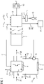
- FIG 1
- eine Umsetzeinrichtung,
- FIG 2
- ein Ablaufdiagramm,
- FIG 3
- eine Kennlinie,
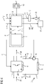
- FIG 4
- eine weitere Umsetzeinrichtung und
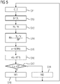
- FIG 5
- ein weiteres Ablaufdiagramm.
- Gemäß
FIG 1 wird mittels einer Umsetzeinrichtung 1 eine der Umsetzeinrichtung 1 zugeführte Eingangsleistung Pin in eine Ausgangsleistung Pout umgesetzt, die von der Umsetzeinrichtung 1 abgegeben wird. Die Ausgangsleistung Pout ist kleiner als die Eingangsleistung Pin. Die Differenz zwischen der Eingangsleistung Pin und der Ausgangsleistung Pout entspricht einer von der Umsetzeinrichtung 1 bewirkten Verlustleistung δP. Die Umsetzeinrichtung 1 ist entsprechend der Darstellung inFIG 1 als Frequenzumrichter ausgebildet. Mittels des Frequenzumrichters kann beispielsweise eine Gleichspannung (erkennbar an "+" und "-" eingangsseitig der Umsetzeinrichtung 1) in eine Wechselspannung (konkret in eine dreiphasige Wechselspannung, erkennbar an den drei Leitungen ausgangsseitig der Umsetzeinrichtung 1) umgesetzt werden. Es sind aber auch andere Ausgestaltungen der Umsetzeinrichtung 1 möglich. Insbesondere könnte der Frequenzumrichter auch in die umgekehrte Richtung arbeiten oder könnte die Umsetzeinrichtung 1 andersartig ausgebildet sein, beispielsweise als Verbrennungsmotor. - Die Umsetzeinrichtung 1 wird in vielen Fällen mittels einer Steuereinrichtung 2 gesteuert. In derartigen Fällen übermittelt die Steuereinrichtung 2 entsprechende Steuersignale C an die Umsetzeinrichtung 1. Die Steuersignale C bestimmen den jeweiligen Ansteuerzustand Z, mit dem die Steuereinrichtung 2 die Umsetzeinrichtung 1 ansteuert.
- Die Umsetzeinrichtung 1 weist einen Kühlmittelkreislauf 3 auf. Der Kühlmittelkreislauf 3 umfasst in der Regel einen Kühlkörper 4, einen Wärmetauscher 5, eine Pumpe 6 sowie die zugehörigen Leitungen 7 zwischen dem Kühlkörper 4, dem Wärmetauscher 5 und der Pumpe 6. In dem Kühlmittelkreislauf 3 fließt ein Kühlmittel 8, mittels dessen die Umsetzeinrichtung 1 gekühlt wird. Das Kühlmittel 8 ist oftmals Wasser, dem bestimmte Zusätze beigefügt sein können. Mittels des Kühlkörpers 4 wird eine Wärmemenge aus der Umsetzeinrichtung 1 abgeführt. Die Wärmemenge korrespondiert im Wesentlichen mit der Verlustleistung δP. Nachfolgend wird daher die abzuführende Wärmemenge mit der Verlustleistung δP gleichgesetzt. Mittels des Wärmetauschers 5 wird die erforderliche Wärmemenge aus dem Kühlmittelkreislauf 3 abgeführt, beispielsweise an die Umgebung abgegeben. Die Pumpe 6 sorgt dafür, dass das Kühlmittel 8 in hinreichender Menge vom Kühlkörper 4 zum Wärmetauscher 5 und von dort wieder zum Kühlkörper 4 geführt wird. Die Pumpe 6 ist oftmals eine geregelte Pumpe. Falls dies der Fall ist, wird die Pumpe 6 von der Steuereinrichtung 2 gesteuert.
- Die Umsetzeinrichtung 1 weist weiterhin eine Überwachungseinrichtung 9 auf. Die Überwachungseinrichtung 9 ist mit einem Computerprogramm 10 programmiert. Das Computerprogramm 10 umfasst Maschinencode 11, der von der Überwachungseinrichtung 9 unmittelbar abarbeitbar ist. Aufgrund der Programmierung der Überwachungseinrichtung 9 mit dem Computerprogramm 10 und der hiermit korrespondierenden Abarbeitung des Maschinencodes 11 durch die Überwachungseinrichtung 9 wird erreicht, dass die Überwachungseinrichtung 9 ein Überwachungsverfahren ausführt, das nachstehend in Verbindung mit
FIG 2 näher erläutert wird. - Gemäß
FIG 2 nimmt die Überwachungseinrichtung 9 in einem Schritt S1 Betriebsdaten der Umsetzeinrichtung 1 und/oder des Kühlmittelkreislaufes 3 entgegen. - Erfindungsgemäß umfassen die Betriebsdaten zumindest eine Vorlauftemperatur TV des Kühlmittelkreislaufes 3, das heißt diejenige Temperatur, mit welcher das Kühlmittel 8 dem Kühlkörper 4 zugeführt wird. Die Vorlauftemperatur TV wird in der Regel mittels eines entsprechenden Temperatursensors 12 messtechnisch erfasst. Weiterhin wird der Überwachungseinrichtung 9 als weiteres Betriebsdatum eine lokale Temperatur TL der Umsetzeinrichtung 1 zugeführt. Die lokale Temperatur TL - bei einem Frequenzumrichter beispielsweise die Sperrschichttemperatur der Halbleiter - wird in der Regel mittels eines entsprechenden Temperatursensors 13 messtechnisch erfasst. Als weitere Betriebsdaten können der Überwachungseinrichtung 9 Messwerte oder rechnerisch ermittelte Werte für die Eingangsleistung Pin und die Ausgangsleistung Pout oder die Verlustleistung δP und damit im Ergebnis charakteristische Werte für die pro Zeiteinheit abzuführende Wärmemenge zugeführt werden.
- In einem Schritt S2 kann die Überwachungseinrichtung 9 beispielsweise zunächst einen Wärmewiderstand Rth ermitteln. Die Überwachungseinrichtung 9 kann den Wärmewiderstand Rth entsprechend der Darstellung in
FIG 2 insbesondere dadurch ermitteln, dass sie die Differenz der lokalen Temperatur TL und der Vorlauftemperatur TV bildet und diese Differenz durch die Differenz von Eingangsleistung Pin und Ausgangsleistung Pout dividiert. Die Differenz von Eingangsleistung Pin und Ausgangsleistung Pout entspricht, wie bereits erwähnt, der Verlustleistung δP und damit im Kern der pro Zeiteinheit abzuführenden Wärmemenge. In einem Schritt S3 kann die Überwachungseinrichtung 9 sodann anhand des ermittelten Wärmewiderstandes Rth die Fließgeschwindigkeit v ermitteln. - Die Ermittlung der Fließgeschwindigkeit v anhand des ermittelten Wärmewiderstandes Rth kann beispielsweise entsprechend der Darstellung in
FIG 3 anhand einer der Überwachungseinrichtung 9 bekannten Kennlinie K erfolgen, welche den funktionalen Verlauf der Fließgeschwindigkeit v als Funktion des Wärmewiderstands Rth (oder umgekehrt) wiedergibt. Die Kennlinie K kann beispielsweise anhand von Geometriedaten des Kühlmittelkreislaufes 3 oder aufgrund einer Messreihe ermittelt werden. Aus der Darstellung der Kennlinie K inFIG 3 ist insbesondere auch ersichtlich, dass der Wärmewiderstand Rth bei einem hohen Volumenstrom und damit einer hohen Fließgeschwindigkeit v gegen einen konstanten Wert strebt, während er bei kleineren Volumenströmen ansteigt. - In einem Schritt S4 vergleicht die Überwachungseinrichtung 9 die ermittelte Fließgeschwindigkeit v mit einer Grenzgeschwindigkeit vG.
- Es ist möglich, dass die Grenzgeschwindigkeit vG der Überwachungseinrichtung 9 fest vorgegeben ist. Vorzugsweise aber ermittelt die Überwachungseinrichtung 9 die Grenzgeschwindigkeit vG in einem dem Schritt S4 vorgeordneten Schritt S5 die Grenzgeschwindigkeit vG. Die Überwachungseinrichtung 9 ermittelt in diesem Fall die Grenzgeschwindigkeit vG anhand einer Temperatur TR der Kühlflüssigkeit 8. Die Überwachungseinrichtung 9 verwertet im Rahmen der Ermittlung der Grenzgeschwindigkeit vG auch das Material des Kühlmittelkreislaufes 3 und die chemische Zusammensetzung des Kühlmittels 8. Diese Größen müssen der Überwachungseinrichtung 9 jedoch nur einmal vorgegeben werden, weil sie sich im Betrieb der Umsetzeinrichtung 1 und des Kühlmittelkreislaufes 3 nicht ändern.
- Als Temperatur TR der Kühlflüssigkeit 8 wird vorzugsweise diejenige Temperatur verwendet, welche im Rücklauf des Kühlmittelkreislaufes 3 auftritt, also nachdem das Kühlmittel 8 den Kühlkörper 4 durchflossen hat. Die Temperatur TR wird, sofern sie verwertet wird, mittels eines entsprechenden Temperatursensors 14 erfasst. Der Schritt S5 ist, weil er nur optional vorhanden ist, in
FIG 2 gestrichelt eingezeichnet. Es kann alternativ zwar auch die Vorlauftemperatur TV verwendet werden. Die Verwendung der Rücklauftemperatur TR ist jedoch vorzuziehen, weil die Rücklauftemperatur TR oberhalb der Vorlauftemperatur TV liegt und die Grenzgeschwindigkeit vG - sofern überhaupt eine Temperaturabhängigkeit der Grenzgeschwindigkeit vG besteht - in aller Regel bei höheren Temperaturen kleiner ist als bei niedrigeren Temperaturen. - Wenn die Überwachungseinrichtung 9 im Schritt S4 feststellt, dass die Fließgeschwindigkeit v die Grenzgeschwindigkeit vG erreicht oder überschreitet, geht die Überwachungseinrichtung 9 zu einem Schritt S6 über. Im Schritt S6 ergreift die Überwachungseinrichtung 9 eine Sonderreaktion. Beispielsweise kann sie eine Alarmmeldung M1 abgeben. Die Alarmmeldung M1 kann beispielsweise über eine Mensch-Maschine-Schnittstelle 15 an eine Bedienperson 16 ausgegeben werden. Alternativ oder zusätzlich ist eine Ausgabe an die Steuereinrichtung 2 möglich. In diesem Fall kann die Steuereinrichtung 2 beispielsweise eine Ansteuerung der Pumpe 6 anpassen, so dass die Fließgeschwindigkeit v reduziert wird. Soweit erforderlich, kann die Steuereinrichtung 2 zusätzlich die Ansteuerung der Umsetzeinrichtung 1 anpassen, so dass eine niedrigere Verlustleistung δP anfällt. Alternativ oder zusätzlich ist eine Ausgabe an eine andere Einrichtung 17 möglich, beispielsweise eine entfernte Rechnereinrichtung, die nicht in die Steuerung der Umsetzeinrichtung 1 und der Pumpe 6 eingebunden ist. Vom Schritt S6 aus geht die Überwachungseinrichtung 9 zum Schritt S1 zurück.
- Wenn die Überwachungseinrichtung 9 im Schritt S4 hingegen feststellt, dass die Fließgeschwindigkeit v die Grenzgeschwindigkeit vG nicht erreicht, ist es möglich, dass die Überwachungseinrichtung 9 vom Schritt S4 aus direkt zum Schritt S1 zurückgeht. In diesem Fall ergreift die Überwachungseinrichtung 9 gar keine Reaktion. Beispielsweise wird die Alarmmeldung M1 nicht ausgegeben. Alternativ ist es möglich, dass die Überwachungseinrichtung 9 in dem Fall, dass die Fließgeschwindigkeit v die Grenzgeschwindigkeit vG nicht erreicht, zu einem Schritt S7 übergeht. Da der Schritt S7 nur optional vorhanden ist, ist er - analog zum Schritt S5 - in
FIG 2 gestrichelt eingezeichnet. - Falls der Schritt S7 vorhanden ist, ergreift die Überwachungseinrichtung 9 im Schritt S7 eine Normalreaktion. Beispielsweise kann die Überwachungseinrichtung 9 eine OK-Meldung M2 abgeben. Die OK-Meldung M2 kann auf die gleiche Art und Weise wie die Alarmmeldung M1 an die Steuereinrichtung 2, über die Mensch-Maschine-Schnittstelle 15 an die Bedienperson 16 und/oder an die andere Einrichtung 17 ausgegeben werden.
- Die Normalreaktion ist eine von der Sonderreaktion verschiedene Reaktion. Wenn beispielsweise das Ausgeben der Alarmmeldung M1 bewirkt, dass eine Signalleuchte der Mensch-Maschine-Schnittstelle 15 derart angesteuert wird, dass die Signalleuchte rot blinkt, kann das Ausgeben der OK-Meldung M2 darin bestehen, dass die Signalleuchte dauerhaft grün leuchtet. Es sind selbstverständlich auch andere Vorgehensweisen möglich.
- Nachstehend werden in Verbindung mit den
FIG 4 und5 eine weitere mögliche Ausgestaltung der Umsetzeinrichtung 1 und die hiermit korrespondierende Betriebsweise der Überwachungseinrichtung 9 erläutert. - In der Ausgestaltung gemäß
FIG 4 ist, wie inFIG 4 durch eine gestrichelte Umrahmung angedeutet, eine der drei folgenden Möglichkeiten realisiert: - die Überwachungseinrichtung 9 ist mit der Steuereinrichtung 2 verbunden oder
- die Überwachungseinrichtung 9 bildet mit der Steuereinrichtung 2 eine Baueinheit bildet oder
- die Überwachungseinrichtung 9 ist mit der Steuereinrichtung 2 identisch.
- In diesen Fällen ist es möglich, dass die Steuereinrichtung 2 die ihr bekannten Daten an die Überwachungseinrichtung 9 übermittelt. Konkret übermittelt die Steuereinrichtung 2 in diesem Fall die Steuersignale C oder den hieraus resultierenden Ansteuerzustand Z an die Überwachungseinrichtung 9. Die Überwachungseinrichtung 9 nimmt die Steuersignale C bzw. den Ansteuerzustand Z gemäß
FIG 5 in einem Schritt S11 entgegen. - In einem Schritt S12 ermittelt die Überwachungseinrichtung 9 in diesem Fall anhand der Steuersignale C oder des Ansteuerzustands Z die Verlustleistung δP (bzw. die abzuführende Wärmemenge) und/oder die lokale Temperatur TL der Umsetzeinrichtung 1. Soweit erforderlich, kann die Überwachungseinrichtung 9 in diesem Zusammenhang auch vorherige Steuersignale C bzw. Ansteuerzustände Z berücksichtigen, so dass sie die Verlustleistung δP (bzw. die abzuführende Wärmemenge) und/oder die lokale Temperatur TL der Umsetzeinrichtung 1 im Ergebnis anhand des zeitlichen Verlaufs des Ansteuerzustands Z ermittelt.
- In einem Schritt S13 nimmt die Überwachungseinrichtung 9 - analog zum Schritt S1 von
FIG 2 die Vorlauftemperatur TV (und gegebenenfalls auch die Rücklauftemperatur TR) entgegen. - An den Schritt S13 schließen sich Schritte S14 bis S19 an. Die Schritte S14 bis S19 korrespondieren 1:1 mit den Schritten S2 bis S7 von
FIG 2 . Es wird daher auf die entsprechenden Ausführungen zu den Schritten S2 bis S7 verwiesen. - Die vorliegende Erfindung weist viele Vorteile auf. Insbesondere kann online und nahezu in Echtzeit die aktuelle Fließgeschwindigkeit v ermittelt werden. Hierauf aufbauend können, soweit erforderlich, sicherheitsgerichtete Reaktionen ergriffen werden. Zur Erfassung der erforderlichen Messwerte können in der Regel bereits vorhandene Komponenten genutzt werden. Die Oxidschicht des Kühlmittelkreislaufes 3 kann geschützt und damit die Lebensdauer des Kühlmittelkreislaufes 3 deutlich gesteigert werden.
- Obwohl die Erfindung im Detail durch das bevorzugte Ausführungsbeispiel näher illustriert und beschrieben wurde, so ist die Erfindung nicht durch die offenbarten Beispiele eingeschränkt und andere Variationen können vom Fachmann hieraus abgeleitet werden, ohne den Schutzumfang der Erfindung zu verlassen.
Claims (9)
- Überwachungsverfahren für einen Kühlmittelkreislauf (3), in dem ein Kühlmittel (8) fließt, mittels dessen eine eine Verlustleistung (δP) bewirkende Umsetzeinrichtung (1) gekühlt wird,- wobei eine Überwachungseinrichtung (9) anhand von Betriebsdaten (TV, TL, δP) der Umsetzeinrichtung (1) und/oder des Kühlmittelkreislaufes (3) eine Fließgeschwindigkeit (v) ermittelt, mit welcher das Kühlmittel (8) in dem Kühlmittelkreislauf (3) fließt,- wobei die Überwachungseinrichtung (9) die ermittelte Fließgeschwindigkeit (v) mit einer Grenzgeschwindigkeit (vG) vergleicht,- wobei die Überwachungseinrichtung (9) eine Sonderreaktion ergreift, wenn die Fließgeschwindigkeit (v) die Grenzgeschwindigkeit (vG) erreicht oder überschreitet,- wobei die Überwachungseinrichtung (9) entweder gar keine Reaktion ergreift oder eine von der Sonderaktion verschiedene Normalreaktion ergreift, solange die Fließgeschwindigkeit (v) die Grenzgeschwindigkeit (vG) nicht erreicht, und- wobei der Überwachungseinrichtung (9) und eine lokale Temperatur (TL) der Umsetzeinrichtung (1) bekannt ist,dadurch gekennzeichnet,- dass der Überwachungseinrichtung (9) eine mittels des Kühlmittels (8) pro Zeiteinheit abzuführende Wärmemenge bekannt ist- dass der Überwachungseinrichtung (9) als Messwert eine Vorlauftemperatur (TV) zugeführt wird, mit welcher das Kühlmittel (8) der Umsetzeinrichtung (1) zugeführt wird, und- dass die Überwachungseinrichtung (9) die Fließgeschwindigkeit (v) anhand der pro Zeiteinheit abzuführenden Wärmemenge, der lokalen Temperatur (TL) der Umsetzeinrichtung (1) und der Vorlauftemperatur (TV) ermittelt.
- Überwachungsverfahren nach Anspruch 1, dadurch gekennzeichnet , dass die Überwachungseinrichtung (9) anhand der pro Zeiteinheit abzuführenden Wärmemenge, der lokalen Temperatur (TL) der Umsetzeinrichtung (1) und der Vorlauftemperatur (TV) zunächst einen Wärmewiderstand (Rth) des Kühlmittelkreislaufes (3) ermittelt und sodann anhand des ermittelten Wärmewiderstandes (Rth) die Fließgeschwindigkeit (v) ermittelt.
- Überwachungsverfahren nach Anspruch 1 oder 2, d a - d u r c h gekennzeichnet , dass die Überwachungseinrichtung (9) mit einer Steuereinrichtung (2) für die Umsetzeinrichtung (1) verbunden ist oder dass die Überwachungseinrichtung (9) mit der Steuereinrichtung (1) eine Baueinheit bildet oder dass die Überwachungseinrichtung (9) mit der Steuereinrichtung (1) identisch ist und dass die Überwachungseinrichtung (9) die abzuführende Wärmemenge und/oder die lokale Temperatur (TL) der Umsetzeinrichtung (1) anhand des zeitlichen Verlaufs eines Ansteuerzustands (Z) ermittelt, mit dem die Steuereinrichtung (2) die Umsetzeinrichtung (1) ansteuert.
- Überwachungsverfahren nach Anspruch 1 oder 2, d a - d u r c h gekennzeichnet , dass die Überwachungseinrichtung (9) Werte für die abzuführende Wärmemenge und/oder die lokale Temperatur (TL) der Umsetzeinrichtung (1) entgegennimmt.
- Überwachungsverfahren nach einem der obigen Ansprüche, dadurch gekennzeichnet,dass die Überwachungseinrichtung (9) die Grenzgeschwindigkeit (vG) anhand einer Temperatur (TR) der Kühlflüssigkeit (8) ermittelt.
- Computerprogramm für eine Überwachungseinrichtung (9) einer Umsetzeinrichtung (1), wobei das Computerprogramm Maschinencode (11) umfasst, der von der Überwachungseinrichtung (9) unmittelbar abarbeitbar ist, wobei die Abarbeitung des Maschinencodes (11) durch die Überwachungseinrichtung (9) bewirkt, dass die Überwachungseinrichtung (9) ein Überwachungsverfahren nach einem der obigen Ansprüche ausführt.
- Überwachungseinrichtung einer Umsetzeinrichtung (1), wobei die Überwachungseinrichtung mit einem Computerprogramm (10) nach Anspruch 6 programmiert ist, so dass die Überwachungseinrichtung im Betrieb ein Überwachungsverfahren nach einem der Ansprüche 1 bis 5 ausführt.
- Umsetzeinrichtung, mittels derer unter Bewirkung von Verlustleistung (δP) eine der Umsetzeinrichtung zugeführte Eingangsleistung (Pin) in eine Ausgangsleistung (Pout) umgesetzt wird, wobei die Umsetzeinrichtung einen Kühlmittelkreislauf (3) aufweist, in dem ein Kühlmittel (8) fließt, mittels dessen die Umsetzeinrichtung gekühlt wird, wobei die Umsetzeinrichtung eine Überwachungseinrichtung (9) nach Anspruch 7 aufweist, die im Betrieb ein Überwachungsverfahren nach einem der Ansprüche 1 bis 6 ausführt.
- Umsetzeinrichtung nach Anspruch 8, dadurch g e - k e n n z e i c h n e t , dass die Umsetzeinrichtung als Frequenzumrichter ausgebildet ist.
Applications Claiming Priority (2)
| Application Number | Priority Date | Filing Date | Title |
|---|---|---|---|
| EP18213067.4A EP3672007A1 (de) | 2018-12-17 | 2018-12-17 | Ermittlung der fliessgeschwindigkeit in einem kühlmittelkreislauf |
| PCT/EP2019/082426 WO2020126330A1 (de) | 2018-12-17 | 2019-11-25 | Ermittlung der fliessgeschwindigkeit in einem kühlmittelkreislauf |
Publications (2)
| Publication Number | Publication Date |
|---|---|
| EP3844852A1 EP3844852A1 (de) | 2021-07-07 |
| EP3844852B1 true EP3844852B1 (de) | 2022-08-10 |
Family
ID=64744443
Family Applications (2)
| Application Number | Title | Priority Date | Filing Date |
|---|---|---|---|
| EP18213067.4A Withdrawn EP3672007A1 (de) | 2018-12-17 | 2018-12-17 | Ermittlung der fliessgeschwindigkeit in einem kühlmittelkreislauf |
| EP19821009.8A Active EP3844852B1 (de) | 2018-12-17 | 2019-11-25 | Ermittlung der fliessgeschwindigkeit in einem kühlmittelkreislauf |
Family Applications Before (1)
| Application Number | Title | Priority Date | Filing Date |
|---|---|---|---|
| EP18213067.4A Withdrawn EP3672007A1 (de) | 2018-12-17 | 2018-12-17 | Ermittlung der fliessgeschwindigkeit in einem kühlmittelkreislauf |
Country Status (4)
| Country | Link |
|---|---|
| US (1) | US11910579B2 (de) |
| EP (2) | EP3672007A1 (de) |
| CN (1) | CN113228444A (de) |
| WO (1) | WO2020126330A1 (de) |
Families Citing this family (2)
| Publication number | Priority date | Publication date | Assignee | Title |
|---|---|---|---|---|
| DE102021129727A1 (de) | 2021-11-15 | 2023-05-17 | Vacon Oy | Elektrischer Leistungswandler, wie beispielsweise ein Elektromotorantrieb, zum Antreiben eines Elektromotors und Verfahren zum Betreiben des Elektromotorantriebs |
| CN121152187B (zh) * | 2025-11-18 | 2026-04-21 | 苏州元脑智能科技有限公司 | 用于冷却液循环系统的控制方法和电子设备 |
Family Cites Families (13)
| Publication number | Priority date | Publication date | Assignee | Title |
|---|---|---|---|---|
| JPH05227648A (ja) * | 1992-02-10 | 1993-09-03 | Koufu Nippon Denki Kk | 水冷電源の異常検出方式 |
| JPH10225099A (ja) * | 1997-02-13 | 1998-08-21 | Toshiba Corp | 電力変換装置 |
| US6842718B2 (en) * | 2003-02-06 | 2005-01-11 | General Electric Company | Intelligent auxiliary cooling system |
| DE102006018771A1 (de) | 2006-04-20 | 2007-10-25 | Siemens Ag | Verfahren zum Überlastschutz elektrischer Bauelemente |
| US8421391B2 (en) * | 2010-05-12 | 2013-04-16 | GM Global Technology Operations LLC | Electric motor stator winding temperature estimation systems and methods |
| JP5521768B2 (ja) * | 2010-05-21 | 2014-06-18 | 株式会社明電舎 | 半導体電力変換装置の冷却装置 |
| JP5633682B2 (ja) * | 2010-06-03 | 2014-12-03 | 日産自動車株式会社 | 電力変換機の制御装置 |
| CN102045903A (zh) * | 2010-12-31 | 2011-05-04 | 北京华进创威电子有限公司 | 用水流继电器保护感应加热线圈的方法 |
| JP5538247B2 (ja) * | 2011-01-18 | 2014-07-02 | 日立オートモティブシステムズ株式会社 | 車載回転電機用電力変換装置の冷却システム |
| CN104713605B (zh) * | 2013-12-16 | 2018-04-13 | 联合汽车电子有限公司 | 电动汽车冷却系统冷却液流量不足故障诊断方法 |
| CN107590295B (zh) * | 2016-07-08 | 2021-02-02 | 台达电子企业管理(上海)有限公司 | 用于功率模块的散热系统状况评估的方法及装置 |
| KR102487157B1 (ko) * | 2016-12-12 | 2023-01-10 | 현대자동차 주식회사 | 열등가회로를 이용한 모터의 온도 연산 시스템 |
| CN108548570B (zh) * | 2018-05-10 | 2021-03-19 | 蔚来(安徽)控股有限公司 | 冷却液流量估计方法、温度估计方法、装置、系统及车辆 |
-
2018
- 2018-12-17 EP EP18213067.4A patent/EP3672007A1/de not_active Withdrawn
-
2019
- 2019-11-25 US US17/414,798 patent/US11910579B2/en active Active
- 2019-11-25 EP EP19821009.8A patent/EP3844852B1/de active Active
- 2019-11-25 WO PCT/EP2019/082426 patent/WO2020126330A1/de not_active Ceased
- 2019-11-25 CN CN201980083417.XA patent/CN113228444A/zh active Pending
Also Published As
| Publication number | Publication date |
|---|---|
| WO2020126330A1 (de) | 2020-06-25 |
| CN113228444A (zh) | 2021-08-06 |
| US11910579B2 (en) | 2024-02-20 |
| US20220022345A1 (en) | 2022-01-20 |
| EP3844852A1 (de) | 2021-07-07 |
| EP3672007A1 (de) | 2020-06-24 |
Similar Documents
| Publication | Publication Date | Title |
|---|---|---|
| EP2229307B1 (de) | Verfahren zur detektion einer thermischen überlastsituation bei einem elektrohandwerkzeug | |
| DE112010003299T5 (de) | Steuerung für die Ölbetriebstemperatur einer hydraulischen Antriebseinrichtung | |
| EP3215763B1 (de) | Verfahren zum betreiben einer fluidführenden einrichtung sowie entsprechende fluidführende einrichtung | |
| DE102011002774A1 (de) | Verfahren zum Füllen und Nachfüllen von Wasser in einen Wasserkreislauf | |
| EP3672007A1 (de) | Ermittlung der fliessgeschwindigkeit in einem kühlmittelkreislauf | |
| DE102014014232B4 (de) | Verfahren zum Überwachen der Werkzeugatmung | |
| EP2200079A1 (de) | Verfahren und Einrichtung zum Betreiben eines Leistungshalbleiterbauelements | |
| EP2817686A1 (de) | Verfahren für die zerspanung eines werkstoffs und nach diesem verfahren arbeitende vorrichtungen | |
| DE102013101104A1 (de) | Kühlanordnung zum Kühlen eines Objekts mit einer Kontrolleinrichtung und Verfahren zur Überwachung einer solchen Kühlanordnung | |
| DE102004043059A1 (de) | Verfahren und Schutzschaltung zur Temperaturüberwachung von kältemittelgekühlten Elektromotoren | |
| EP1380485B1 (de) | Verfahren zur Begrenzung der Bremswirkung eines Retarders in Abhängigkeit von der Temperatur | |
| EP1129915A2 (de) | Verfahren zur Verbesserung der Verfügbarkeit einer Antriebsmaschine und Steuer- und/ oder Regelvorrichtung | |
| DE102021003218A1 (de) | Vorrichtung und Verfahren zum Betrieb eines automatisiert betriebenen Fortbewegungsmittels | |
| EP0617239A2 (de) | Verfahren zur überwachung des Verschmutzungs- und/oder Verkalkungszustandes von Wärmetauschern in Heiz- oder Kühlanlagen | |
| DE102012017207A1 (de) | Verfahren zum Ansteuern einer hydraulischen Ventilanordnung und hydraulische Ventilanordnung | |
| DE102016116182A1 (de) | Temperaturmanagement für eine Kraftmesseinrichtung | |
| DE102019113131A1 (de) | Hochdruckreinigungssystem | |
| EP2011706A2 (de) | Verfahren zur Regelung eines Retarders eines Kraftfahrzeugs | |
| EP1788328B1 (de) | Verfahren zum Zuführen und Abführen eines Kühlmediums zu und von einer Verlustwärme erzeugenden Verbrauchereinheit | |
| DE10161867B4 (de) | Verfahren zur Überwachung eines Flüssigkeits-Kühlkreislaufs einer Brennkraftmaschine | |
| DE102011120686A1 (de) | Verfahren zum Überwachen einer Pumpe | |
| DE112022000330T5 (de) | Temperaturschutzvorrichtung und steuervorrichtung | |
| EP3263953A1 (de) | Hydrostatischer antrieb mit geschlossenem kreislauf und verfahren zum betrieb des antriebs | |
| DE102025102014B3 (de) | Verfahren und System zum Bestimmen eines Zustands eines Fahrzeugs | |
| EP3654479A1 (de) | Schutzschaltung für ein stromkreiselement mit mindestens einer funktionalen ausrichtung als vorladewiderstand |
Legal Events
| Date | Code | Title | Description |
|---|---|---|---|
| STAA | Information on the status of an ep patent application or granted ep patent |
Free format text: STATUS: UNKNOWN |
|
| STAA | Information on the status of an ep patent application or granted ep patent |
Free format text: STATUS: THE INTERNATIONAL PUBLICATION HAS BEEN MADE |
|
| STAA | Information on the status of an ep patent application or granted ep patent |
Free format text: STATUS: REQUEST FOR EXAMINATION WAS MADE |
|
| PUAI | Public reference made under article 153(3) epc to a published international application that has entered the european phase |
Free format text: ORIGINAL CODE: 0009012 |
|
| 17P | Request for examination filed |
Effective date: 20210329 |
|
| AK | Designated contracting states |
Kind code of ref document: A1 Designated state(s): AL AT BE BG CH CY CZ DE DK EE ES FI FR GB GR HR HU IE IS IT LI LT LU LV MC MK MT NL NO PL PT RO RS SE SI SK SM TR |
|
| DAV | Request for validation of the european patent (deleted) | ||
| DAX | Request for extension of the european patent (deleted) | ||
| GRAP | Despatch of communication of intention to grant a patent |
Free format text: ORIGINAL CODE: EPIDOSNIGR1 |
|
| STAA | Information on the status of an ep patent application or granted ep patent |
Free format text: STATUS: GRANT OF PATENT IS INTENDED |
|
| INTG | Intention to grant announced |
Effective date: 20220413 |
|
| GRAS | Grant fee paid |
Free format text: ORIGINAL CODE: EPIDOSNIGR3 |
|
| GRAA | (expected) grant |
Free format text: ORIGINAL CODE: 0009210 |
|
| STAA | Information on the status of an ep patent application or granted ep patent |
Free format text: STATUS: THE PATENT HAS BEEN GRANTED |
|
| AK | Designated contracting states |
Kind code of ref document: B1 Designated state(s): AL AT BE BG CH CY CZ DE DK EE ES FI FR GB GR HR HU IE IS IT LI LT LU LV MC MK MT NL NO PL PT RO RS SE SI SK SM TR |
|
| REG | Reference to a national code |
Ref country code: AT Ref legal event code: REF Ref document number: 1511267 Country of ref document: AT Kind code of ref document: T Effective date: 20220815 Ref country code: CH Ref legal event code: EP |
|
| REG | Reference to a national code |
Ref country code: IE Ref legal event code: FG4D Free format text: LANGUAGE OF EP DOCUMENT: GERMAN |
|
| REG | Reference to a national code |
Ref country code: DE Ref legal event code: R096 Ref document number: 502019005293 Country of ref document: DE |
|
| REG | Reference to a national code |
Ref country code: NL Ref legal event code: MP Effective date: 20220810 |
|
| REG | Reference to a national code |
Ref country code: LT Ref legal event code: MG9D |
|
| PG25 | Lapsed in a contracting state [announced via postgrant information from national office to epo] |
Ref country code: SE Free format text: LAPSE BECAUSE OF FAILURE TO SUBMIT A TRANSLATION OF THE DESCRIPTION OR TO PAY THE FEE WITHIN THE PRESCRIBED TIME-LIMIT Effective date: 20220810 Ref country code: RS Free format text: LAPSE BECAUSE OF FAILURE TO SUBMIT A TRANSLATION OF THE DESCRIPTION OR TO PAY THE FEE WITHIN THE PRESCRIBED TIME-LIMIT Effective date: 20220810 Ref country code: PT Free format text: LAPSE BECAUSE OF FAILURE TO SUBMIT A TRANSLATION OF THE DESCRIPTION OR TO PAY THE FEE WITHIN THE PRESCRIBED TIME-LIMIT Effective date: 20221212 Ref country code: NO Free format text: LAPSE BECAUSE OF FAILURE TO SUBMIT A TRANSLATION OF THE DESCRIPTION OR TO PAY THE FEE WITHIN THE PRESCRIBED TIME-LIMIT Effective date: 20221110 Ref country code: NL Free format text: LAPSE BECAUSE OF FAILURE TO SUBMIT A TRANSLATION OF THE DESCRIPTION OR TO PAY THE FEE WITHIN THE PRESCRIBED TIME-LIMIT Effective date: 20220810 Ref country code: LV Free format text: LAPSE BECAUSE OF FAILURE TO SUBMIT A TRANSLATION OF THE DESCRIPTION OR TO PAY THE FEE WITHIN THE PRESCRIBED TIME-LIMIT Effective date: 20220810 Ref country code: LT Free format text: LAPSE BECAUSE OF FAILURE TO SUBMIT A TRANSLATION OF THE DESCRIPTION OR TO PAY THE FEE WITHIN THE PRESCRIBED TIME-LIMIT Effective date: 20220810 Ref country code: FI Free format text: LAPSE BECAUSE OF FAILURE TO SUBMIT A TRANSLATION OF THE DESCRIPTION OR TO PAY THE FEE WITHIN THE PRESCRIBED TIME-LIMIT Effective date: 20220810 |
|
| PG25 | Lapsed in a contracting state [announced via postgrant information from national office to epo] |
Ref country code: PL Free format text: LAPSE BECAUSE OF FAILURE TO SUBMIT A TRANSLATION OF THE DESCRIPTION OR TO PAY THE FEE WITHIN THE PRESCRIBED TIME-LIMIT Effective date: 20220810 Ref country code: IS Free format text: LAPSE BECAUSE OF FAILURE TO SUBMIT A TRANSLATION OF THE DESCRIPTION OR TO PAY THE FEE WITHIN THE PRESCRIBED TIME-LIMIT Effective date: 20221210 Ref country code: HR Free format text: LAPSE BECAUSE OF FAILURE TO SUBMIT A TRANSLATION OF THE DESCRIPTION OR TO PAY THE FEE WITHIN THE PRESCRIBED TIME-LIMIT Effective date: 20220810 Ref country code: GR Free format text: LAPSE BECAUSE OF FAILURE TO SUBMIT A TRANSLATION OF THE DESCRIPTION OR TO PAY THE FEE WITHIN THE PRESCRIBED TIME-LIMIT Effective date: 20221111 |
|
| PG25 | Lapsed in a contracting state [announced via postgrant information from national office to epo] |
Ref country code: SM Free format text: LAPSE BECAUSE OF FAILURE TO SUBMIT A TRANSLATION OF THE DESCRIPTION OR TO PAY THE FEE WITHIN THE PRESCRIBED TIME-LIMIT Effective date: 20220810 Ref country code: RO Free format text: LAPSE BECAUSE OF FAILURE TO SUBMIT A TRANSLATION OF THE DESCRIPTION OR TO PAY THE FEE WITHIN THE PRESCRIBED TIME-LIMIT Effective date: 20220810 Ref country code: ES Free format text: LAPSE BECAUSE OF FAILURE TO SUBMIT A TRANSLATION OF THE DESCRIPTION OR TO PAY THE FEE WITHIN THE PRESCRIBED TIME-LIMIT Effective date: 20220810 Ref country code: DK Free format text: LAPSE BECAUSE OF FAILURE TO SUBMIT A TRANSLATION OF THE DESCRIPTION OR TO PAY THE FEE WITHIN THE PRESCRIBED TIME-LIMIT Effective date: 20220810 Ref country code: CZ Free format text: LAPSE BECAUSE OF FAILURE TO SUBMIT A TRANSLATION OF THE DESCRIPTION OR TO PAY THE FEE WITHIN THE PRESCRIBED TIME-LIMIT Effective date: 20220810 |
|
| REG | Reference to a national code |
Ref country code: DE Ref legal event code: R097 Ref document number: 502019005293 Country of ref document: DE |
|
| PG25 | Lapsed in a contracting state [announced via postgrant information from national office to epo] |
Ref country code: SK Free format text: LAPSE BECAUSE OF FAILURE TO SUBMIT A TRANSLATION OF THE DESCRIPTION OR TO PAY THE FEE WITHIN THE PRESCRIBED TIME-LIMIT Effective date: 20220810 Ref country code: EE Free format text: LAPSE BECAUSE OF FAILURE TO SUBMIT A TRANSLATION OF THE DESCRIPTION OR TO PAY THE FEE WITHIN THE PRESCRIBED TIME-LIMIT Effective date: 20220810 |
|
| PLBE | No opposition filed within time limit |
Free format text: ORIGINAL CODE: 0009261 |
|
| STAA | Information on the status of an ep patent application or granted ep patent |
Free format text: STATUS: NO OPPOSITION FILED WITHIN TIME LIMIT |
|
| PG25 | Lapsed in a contracting state [announced via postgrant information from national office to epo] |
Ref country code: MC Free format text: LAPSE BECAUSE OF FAILURE TO SUBMIT A TRANSLATION OF THE DESCRIPTION OR TO PAY THE FEE WITHIN THE PRESCRIBED TIME-LIMIT Effective date: 20220810 Ref country code: AL Free format text: LAPSE BECAUSE OF FAILURE TO SUBMIT A TRANSLATION OF THE DESCRIPTION OR TO PAY THE FEE WITHIN THE PRESCRIBED TIME-LIMIT Effective date: 20220810 |
|
| REG | Reference to a national code |
Ref country code: CH Ref legal event code: PL |
|
| 26N | No opposition filed |
Effective date: 20230511 |
|
| REG | Reference to a national code |
Ref country code: BE Ref legal event code: MM Effective date: 20221130 |
|
| PG25 | Lapsed in a contracting state [announced via postgrant information from national office to epo] |
Ref country code: LI Free format text: LAPSE BECAUSE OF NON-PAYMENT OF DUE FEES Effective date: 20221130 Ref country code: CH Free format text: LAPSE BECAUSE OF NON-PAYMENT OF DUE FEES Effective date: 20221130 |
|
| PG25 | Lapsed in a contracting state [announced via postgrant information from national office to epo] |
Ref country code: SI Free format text: LAPSE BECAUSE OF FAILURE TO SUBMIT A TRANSLATION OF THE DESCRIPTION OR TO PAY THE FEE WITHIN THE PRESCRIBED TIME-LIMIT Effective date: 20220810 Ref country code: LU Free format text: LAPSE BECAUSE OF NON-PAYMENT OF DUE FEES Effective date: 20221125 |
|
| PG25 | Lapsed in a contracting state [announced via postgrant information from national office to epo] |
Ref country code: IE Free format text: LAPSE BECAUSE OF NON-PAYMENT OF DUE FEES Effective date: 20221125 |
|
| PG25 | Lapsed in a contracting state [announced via postgrant information from national office to epo] |
Ref country code: FR Free format text: LAPSE BECAUSE OF NON-PAYMENT OF DUE FEES Effective date: 20221130 Ref country code: BE Free format text: LAPSE BECAUSE OF NON-PAYMENT OF DUE FEES Effective date: 20221130 |
|
| PG25 | Lapsed in a contracting state [announced via postgrant information from national office to epo] |
Ref country code: CY Free format text: LAPSE BECAUSE OF FAILURE TO SUBMIT A TRANSLATION OF THE DESCRIPTION OR TO PAY THE FEE WITHIN THE PRESCRIBED TIME-LIMIT Effective date: 20220810 |
|
| PG25 | Lapsed in a contracting state [announced via postgrant information from national office to epo] |
Ref country code: MK Free format text: LAPSE BECAUSE OF FAILURE TO SUBMIT A TRANSLATION OF THE DESCRIPTION OR TO PAY THE FEE WITHIN THE PRESCRIBED TIME-LIMIT Effective date: 20220810 Ref country code: HU Free format text: LAPSE BECAUSE OF FAILURE TO SUBMIT A TRANSLATION OF THE DESCRIPTION OR TO PAY THE FEE WITHIN THE PRESCRIBED TIME-LIMIT; INVALID AB INITIO Effective date: 20191125 |
|
| PG25 | Lapsed in a contracting state [announced via postgrant information from national office to epo] |
Ref country code: TR Free format text: LAPSE BECAUSE OF FAILURE TO SUBMIT A TRANSLATION OF THE DESCRIPTION OR TO PAY THE FEE WITHIN THE PRESCRIBED TIME-LIMIT Effective date: 20220810 |
|
| GBPC | Gb: european patent ceased through non-payment of renewal fee |
Effective date: 20231125 |
|
| PG25 | Lapsed in a contracting state [announced via postgrant information from national office to epo] |
Ref country code: BG Free format text: LAPSE BECAUSE OF FAILURE TO SUBMIT A TRANSLATION OF THE DESCRIPTION OR TO PAY THE FEE WITHIN THE PRESCRIBED TIME-LIMIT Effective date: 20220810 |
|
| PG25 | Lapsed in a contracting state [announced via postgrant information from national office to epo] |
Ref country code: MT Free format text: LAPSE BECAUSE OF FAILURE TO SUBMIT A TRANSLATION OF THE DESCRIPTION OR TO PAY THE FEE WITHIN THE PRESCRIBED TIME-LIMIT Effective date: 20220810 |
|
| PG25 | Lapsed in a contracting state [announced via postgrant information from national office to epo] |
Ref country code: GB Free format text: LAPSE BECAUSE OF NON-PAYMENT OF DUE FEES Effective date: 20231125 |
|
| PG25 | Lapsed in a contracting state [announced via postgrant information from national office to epo] |
Ref country code: GB Free format text: LAPSE BECAUSE OF NON-PAYMENT OF DUE FEES Effective date: 20231125 |
|
| PG25 | Lapsed in a contracting state [announced via postgrant information from national office to epo] |
Ref country code: AT Free format text: LAPSE BECAUSE OF NON-PAYMENT OF DUE FEES Effective date: 20241125 |
|
| PGFP | Annual fee paid to national office [announced via postgrant information from national office to epo] |
Ref country code: IT Payment date: 20251125 Year of fee payment: 7 |
|
| REG | Reference to a national code |
Ref country code: AT Ref legal event code: MM01 Ref document number: 1511267 Country of ref document: AT Kind code of ref document: T Effective date: 20241125 |
|
| PGFP | Annual fee paid to national office [announced via postgrant information from national office to epo] |
Ref country code: DE Payment date: 20260119 Year of fee payment: 7 |
|
| PGFP | Annual fee paid to national office [announced via postgrant information from national office to epo] |
Ref country code: AT Payment date: 20260410 Year of fee payment: 5 |