EP3844449B1 - Hybrid thermosiphon system - Google Patents
Hybrid thermosiphon system Download PDFInfo
- Publication number
- EP3844449B1 EP3844449B1 EP19854286.2A EP19854286A EP3844449B1 EP 3844449 B1 EP3844449 B1 EP 3844449B1 EP 19854286 A EP19854286 A EP 19854286A EP 3844449 B1 EP3844449 B1 EP 3844449B1
- Authority
- EP
- European Patent Office
- Prior art keywords
- thermosiphon
- hybrid
- evaporator
- refrigeration system
- operable
- Prior art date
- Legal status (The legal status is an assumption and is not a legal conclusion. Google has not performed a legal analysis and makes no representation as to the accuracy of the status listed.)
- Active
Links
Images


Classifications
-
- F—MECHANICAL ENGINEERING; LIGHTING; HEATING; WEAPONS; BLASTING
- F28—HEAT EXCHANGE IN GENERAL
- F28D—HEAT-EXCHANGE APPARATUS, NOT PROVIDED FOR IN ANOTHER SUBCLASS, IN WHICH THE HEAT-EXCHANGE MEDIA DO NOT COME INTO DIRECT CONTACT
- F28D1/00—Heat-exchange apparatus having stationary conduit assemblies for one heat-exchange medium only, the media being in contact with different sides of the conduit wall, in which the other heat-exchange medium is a large body of fluid, e.g. domestic or motor car radiators
- F28D1/02—Heat-exchange apparatus having stationary conduit assemblies for one heat-exchange medium only, the media being in contact with different sides of the conduit wall, in which the other heat-exchange medium is a large body of fluid, e.g. domestic or motor car radiators with heat-exchange conduits immersed in the body of fluid
- F28D1/0226—Heat-exchange apparatus having stationary conduit assemblies for one heat-exchange medium only, the media being in contact with different sides of the conduit wall, in which the other heat-exchange medium is a large body of fluid, e.g. domestic or motor car radiators with heat-exchange conduits immersed in the body of fluid with an intermediate heat-transfer medium, e.g. thermosiphon radiators
-
- F—MECHANICAL ENGINEERING; LIGHTING; HEATING; WEAPONS; BLASTING
- F24—HEATING; RANGES; VENTILATING
- F24S—SOLAR HEAT COLLECTORS; SOLAR HEAT SYSTEMS
- F24S10/00—Solar heat collectors using working fluids
- F24S10/90—Solar heat collectors using working fluids using internal thermosiphonic circulation
- F24S10/95—Solar heat collectors using working fluids using internal thermosiphonic circulation having evaporator sections and condenser sections, e.g. heat pipes
-
- F—MECHANICAL ENGINEERING; LIGHTING; HEATING; WEAPONS; BLASTING
- F24—HEATING; RANGES; VENTILATING
- F24S—SOLAR HEAT COLLECTORS; SOLAR HEAT SYSTEMS
- F24S90/00—Solar heat systems not otherwise provided for
- F24S90/10—Solar heat systems not otherwise provided for using thermosiphonic circulation
-
- F—MECHANICAL ENGINEERING; LIGHTING; HEATING; WEAPONS; BLASTING
- F28—HEAT EXCHANGE IN GENERAL
- F28D—HEAT-EXCHANGE APPARATUS, NOT PROVIDED FOR IN ANOTHER SUBCLASS, IN WHICH THE HEAT-EXCHANGE MEDIA DO NOT COME INTO DIRECT CONTACT
- F28D15/00—Heat-exchange apparatus with the intermediate heat-transfer medium in closed tubes passing into or through the conduit walls ; Heat-exchange apparatus employing intermediate heat-transfer medium or bodies
- F28D15/02—Heat-exchange apparatus with the intermediate heat-transfer medium in closed tubes passing into or through the conduit walls ; Heat-exchange apparatus employing intermediate heat-transfer medium or bodies in which the medium condenses and evaporates, e.g. heat pipes
- F28D15/0266—Heat-exchange apparatus with the intermediate heat-transfer medium in closed tubes passing into or through the conduit walls ; Heat-exchange apparatus employing intermediate heat-transfer medium or bodies in which the medium condenses and evaporates, e.g. heat pipes with separate evaporating and condensing chambers connected by at least one conduit; Loop-type heat pipes; with multiple or common evaporating or condensing chambers
-
- F—MECHANICAL ENGINEERING; LIGHTING; HEATING; WEAPONS; BLASTING
- F24—HEATING; RANGES; VENTILATING
- F24T—GEOTHERMAL COLLECTORS; GEOTHERMAL SYSTEMS
- F24T10/00—Geothermal collectors
- F24T10/10—Geothermal collectors with circulation of working fluids through underground channels, the working fluids not coming into direct contact with the ground
-
- F—MECHANICAL ENGINEERING; LIGHTING; HEATING; WEAPONS; BLASTING
- F24—HEATING; RANGES; VENTILATING
- F24T—GEOTHERMAL COLLECTORS; GEOTHERMAL SYSTEMS
- F24T10/00—Geothermal collectors
- F24T10/40—Geothermal collectors operated without external energy sources, e.g. using thermosiphonic circulation or heat pipes
-
- F—MECHANICAL ENGINEERING; LIGHTING; HEATING; WEAPONS; BLASTING
- F24—HEATING; RANGES; VENTILATING
- F24T—GEOTHERMAL COLLECTORS; GEOTHERMAL SYSTEMS
- F24T10/00—Geothermal collectors
- F24T2010/50—Component parts, details or accessories
- F24T2010/53—Methods for installation
-
- F—MECHANICAL ENGINEERING; LIGHTING; HEATING; WEAPONS; BLASTING
- F24—HEATING; RANGES; VENTILATING
- F24T—GEOTHERMAL COLLECTORS; GEOTHERMAL SYSTEMS
- F24T50/00—Geothermal systems
-
- F—MECHANICAL ENGINEERING; LIGHTING; HEATING; WEAPONS; BLASTING
- F28—HEAT EXCHANGE IN GENERAL
- F28D—HEAT-EXCHANGE APPARATUS, NOT PROVIDED FOR IN ANOTHER SUBCLASS, IN WHICH THE HEAT-EXCHANGE MEDIA DO NOT COME INTO DIRECT CONTACT
- F28D20/00—Heat storage plants or apparatus in general; Regenerative heat-exchange apparatus not covered by groups F28D17/00 or F28D19/00
- F28D2020/0065—Details, e.g. particular heat storage tanks, auxiliary members within tanks
- F28D2020/0069—Distributing arrangements; Fluid deflecting means
-
- Y—GENERAL TAGGING OF NEW TECHNOLOGICAL DEVELOPMENTS; GENERAL TAGGING OF CROSS-SECTIONAL TECHNOLOGIES SPANNING OVER SEVERAL SECTIONS OF THE IPC; TECHNICAL SUBJECTS COVERED BY FORMER USPC CROSS-REFERENCE ART COLLECTIONS [XRACs] AND DIGESTS
- Y02—TECHNOLOGIES OR APPLICATIONS FOR MITIGATION OR ADAPTATION AGAINST CLIMATE CHANGE
- Y02B—CLIMATE CHANGE MITIGATION TECHNOLOGIES RELATED TO BUILDINGS, e.g. HOUSING, HOUSE APPLIANCES OR RELATED END-USER APPLICATIONS
- Y02B10/00—Integration of renewable energy sources in buildings
- Y02B10/20—Solar thermal
-
- Y—GENERAL TAGGING OF NEW TECHNOLOGICAL DEVELOPMENTS; GENERAL TAGGING OF CROSS-SECTIONAL TECHNOLOGIES SPANNING OVER SEVERAL SECTIONS OF THE IPC; TECHNICAL SUBJECTS COVERED BY FORMER USPC CROSS-REFERENCE ART COLLECTIONS [XRACs] AND DIGESTS
- Y02—TECHNOLOGIES OR APPLICATIONS FOR MITIGATION OR ADAPTATION AGAINST CLIMATE CHANGE
- Y02E—REDUCTION OF GREENHOUSE GAS [GHG] EMISSIONS, RELATED TO ENERGY GENERATION, TRANSMISSION OR DISTRIBUTION
- Y02E10/00—Energy generation through renewable energy sources
- Y02E10/10—Geothermal energy
-
- Y—GENERAL TAGGING OF NEW TECHNOLOGICAL DEVELOPMENTS; GENERAL TAGGING OF CROSS-SECTIONAL TECHNOLOGIES SPANNING OVER SEVERAL SECTIONS OF THE IPC; TECHNICAL SUBJECTS COVERED BY FORMER USPC CROSS-REFERENCE ART COLLECTIONS [XRACs] AND DIGESTS
- Y02—TECHNOLOGIES OR APPLICATIONS FOR MITIGATION OR ADAPTATION AGAINST CLIMATE CHANGE
- Y02E—REDUCTION OF GREENHOUSE GAS [GHG] EMISSIONS, RELATED TO ENERGY GENERATION, TRANSMISSION OR DISTRIBUTION
- Y02E10/00—Energy generation through renewable energy sources
- Y02E10/40—Solar thermal energy, e.g. solar towers
- Y02E10/44—Heat exchange systems
Definitions
- thermosiphon systems relate generally to thermosiphon systems, and in particular, to such systems designed to maintain the stability and integrity of permafrost soils underneath structures.
- thermosiphon cooling system that combines the advantages of both passive and active cooling for improved overall performance.
- the improved system would continue to cool passively when air temperatures are sufficiently low, then provide powered active cooling as needed when air temperatures rise above the passive cooling threshold.
- Examples of a passive-active thermosiphon configured for freezing an area of soil according to the preamble of claim 1 are disclosed in US5327734 A and US5339893 A .
- Each of these documents discloses a thermosiphon including an evaporator section, a condenser section, and a refrigeration or heat exchange system operable to actively cool the condenser section. Additional aspects and advantages of the present invention will be apparent from the following detailed description of example embodiments, which proceeds with reference to the accompanying drawings. It should be understood that the drawings depict only certain example embodiments and are not to be considered as limiting in nature.
- thermosiphon system 10 designed to maintain permafrost levels underneath buildings or structures 14 with minimal energy consumption.
- the disclosed thermosiphon system 10 may increase the stability of permafrost layers by consistently maintaining the frozen soil levels in such a manner so as to minimize the impact of seasonal cooling and heating. For example, during the cooler seasons when the air temperature is below freezing, the thermosiphon system 10 is able to efficiently maintain the permafrost layer by using the cold air temperature to provide sufficient cooling. When the air temperature rises above freezing during the warmer months, the thermosiphon system 10 provides additional cooling via an active refrigeration system 26 to minimize thawing or degradation of the permafrost layer.
- thermosiphon system 10 strives to continuously maintain the permafrost layer at a consistent level (e.g., by minimizing thawing) despite seasonal temperate changes to avoid the need to refreeze regions of the permafrost that may have thawed, thereby reducing overall power consumption during the warmer months. Additional details and advantages of the thermosiphon system 10 are discussed below with reference to FIGS. 1-3 .
- FIG. 1 schematically illustrates various components of a thermosiphon system 10 designed to maintain the active frost layer 12 in a frozen state to avoid potential degradation and destabilization of the foundation underneath a structure or building 14.
- the structure 14 may be built upon rock or soil that includes a permafrost layer 8 and an active frost layer 12.
- the permafrost layer 8 consists of rock and/or soil that remains at or below the freezing point of water such that the layer remains frozen.
- the active frost layer 12 includes rock and/or soil that freezes and thaws annually due to seasonal and climate changes.
- the building design and foundation must account for the repeated freezing and thawing cycles of the ground to avoid potential structural integrity issues, which may eventually lead to the structure 14 being unsafe or uninhabitable.
- the following description provides a brief overview of the components of the hybrid thermosiphon system 10 and their interaction with reference to FIG. 1 , followed by a more detailed discussion relating to the structure and function of the active cooling system 32.
- the thermosiphon system 10 includes a plurality of thermosiphon evaporator pipes 16 each installed into the ground surface layer 18.
- the evaporator pipes 16 are arranged generally vertically relative to the ground surface layer 18 and include a lower pipe tail section 20 that extends below the surface layer 18 and into or through the active frost layer 12.
- Each evaporator pipe 16 is enclosed and houses a refrigerant or cooling fluid (e.g., a gas or liquid) that runs through to the lower pipe tail section 20.
- thermosiphon system 10 relies on the cold environmental air to cool the refrigerant in the evaporator pipes 16, which in turn extracts heat from the active frost layer 12 via an evaporation process.
- the refrigerant removes heat from the active frost layer 12 through the lower pipe tail section 20, the vapors of which move upwardly through the evaporator pipe 16 toward a thermosiphon condenser 22. Condensation occurs at the condenser 22, causing the refrigerant to flow downwardly against the walls of the evaporator pipes 16 to continue the refrigeration cycle where the refrigerant continues drawing heat from the soil to maintain the active frost layer 12 in a frozen state.
- This refrigeration cycle continues to operate in a passive state as long as the air temperature above the ground surface layer 18 is cooler than the temperature of the active permafrost layer 12.
- thermosiphon condenser 22 can no longer operate passively as described above. In such instances, a supplementary form of refrigeration is required to condense the refrigerant in the vertical portion of the thermosiphon evaporator pipe 16 below the condenser 22 to maintain the active frost layer 12 (and to some extent, the permafrost layer 8) in a frozen condition.
- the hybrid thermosiphon system 10 further includes a powered active cooling system 32. Additional details of the active cooling system 32 and its components is described in further detail below with collective reference to FIGS. 2-3 .
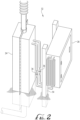
- FIGS. 2 and 3 collectively illustrate details of the active cooling system 32 and its components.
- the active cooling system 32 includes an insulated evaporator system 24 and a refrigeration system 26 coupled to one another.
- the following section begins with a description of the insulated evaporator system 24 and its components, followed by a discussion of the refrigeration system 26 and its components and a discussion relating to the interaction of the two systems 24, 26.
- the insulated evaporator system 24 includes a durable insulated shell 28 that surrounds the evaporator (or heat exchanger) portion 30 of the active cooling system 32.
- the shell 28 may include two separate shell portions that are removably coupled to one another to enclose the evaporator 30.
- the shell portions may be coupled in any one of various suitable methods.
- the evaporator 30 and the shell 28 are installed onto the thermosiphon evaporator pipe 16 below a position of the thermosiphon condenser 22 without need for modification of the thermosiphon or other existing components.
- a lower portion of the shell 28 is buried into the ground surface layer 18.
- the refrigeration system 26 includes a durable, weatherproof enclosure 46 housing the electrical and mechanical components of the active refrigeration system.
- the refrigeration system 26 houses a cooling fluid, such as a mixture of liquid and gas phase refrigerant, which is delivered to the evaporator 30 via the conduits 48 (e.g., flexible piping) at a sufficiently low temperature to cause condensation inside the thermosiphon condenser 22, thereby allowing the thermosiphon system to continue operating in a similar fashion as the passive state described above.
- a cooling fluid such as a mixture of liquid and gas phase refrigerant
- the conduits 48 e.g., flexible piping
- heat from the thermosiphon is transferred to the evaporator 30, evaporating the refrigerant, which then is returned to the refrigeration system 26 via the conduits 48.
- the refrigeration system 26 condenses the refrigerant and releases the heat to the atmosphere through condensers 50 which are coupled to the refrigeration system enclosure 48 before returning low temperature refrigerant back to the evaporator 30 to continue
- the refrigeration system 26 may be coupled to vertical supports 54 adjacent the evaporator system 24. In other embodiments, the refrigeration system 26 may be coupled directly to the evaporator system 24 along the shell 28.
- the conduits 48 include self-sealing quick disconnect fittings 36 to connect the evaporator system 24 and refrigeration system 26.
- the fittings 36 provide a number of advantages for the thermosiphon system 10. For example, the fittings 36 allow the systems 24, 26 to be easily separated from one another without the need to remove the cooling fluid. This design also simplifies transportation of the systems 24, 26 to and from the often remote locations in which the thermosiphon system 10 is installed.
- fittings 36 simplify and reduce the cost of installation by eliminating the need for a licensed refrigerant technician on-site since units can be charged with refrigerant in an urban center prior to transport. Moreover, the fittings 36 facilitate repair/maintenance work that may be needed for the systems 24, 26 without requiring an on-site technician since the systems 24, 26 may be transported individually as needed.
- the refrigeration system 26 preferably includes a heater 42, a cooling unit 44 (such as a combination cooling coil and fan), a compressor head pressure control 53, and a hot gas bypass control 52 to facilitate reliable operation under a wide range of heat loads and environmental conditions. These components may be controlled by a process controller 38 and operated to maximize efficiency of the overall system.
- a cooling unit 44 such as a combination cooling coil and fan
- a compressor head pressure control 53 to facilitate reliable operation under a wide range of heat loads and environmental conditions.
- a hot gas bypass control 52 to facilitate reliable operation under a wide range of heat loads and environmental conditions.
- thermosiphon system 10 may further include temperature and/or pressure sensors (not shown) operable to determine the temperature of the thermosiphon and the operating conditions within the refrigeration system 26. When specific temperature and pressure parameters are met, the respective sensor(s) may send a signal to the process controller 38. Upon receiving the signal, the compressor 40 may be activated and begin cooling to continue the refrigeration cycle and maintain the active frost layer 12 in a frozen state. In some embodiments, the process controller 38 may be programmed to vary the speed of the compressor 40 to further stabilize system operating conditions as needed.
- the system 10 may further include a variety of solar panels 56 used to power the refrigeration system 26.
- the structure 14 may include an array of solar panels 56 arranged to generate electricity throughout the year, primarily during the warmer summer months and shoulder seasons. Accordingly, during operation, the power generated by the solar panels 56 may be used to offset the power consumption of the active cooling system 32.
- the active cooling system 32 may operate via a conventional power source, such as batteries or fuel, by a combination of solar energy and a conventional power source, or any other suitable power sources.
- the size of the active cooling system 32 components determines the rate of cooling and heat extraction within the evaporator pipes 16.
- the active cooling system 32 has sufficient capacity so as to maintain the active frost layer 12 sufficiently cooled to avoid thawing cycles.
- the system 10 may include a plurality of active cooling systems 32 operable to service a number of thermosiphon evaporator pipes 16.
- each evaporator pipe 16 may include an active cooling system 32. It should be understood that in other embodiments, any suitable number of active refrigeration systems 32 may be used as needed.
Landscapes
- Engineering & Computer Science (AREA)
- Mechanical Engineering (AREA)
- General Engineering & Computer Science (AREA)
- Life Sciences & Earth Sciences (AREA)
- Sustainable Development (AREA)
- Physics & Mathematics (AREA)
- Thermal Sciences (AREA)
- Sustainable Energy (AREA)
- Chemical & Material Sciences (AREA)
- Combustion & Propulsion (AREA)
- Devices That Are Associated With Refrigeration Equipment (AREA)
- Acyclic And Carbocyclic Compounds In Medicinal Compositions (AREA)
Description
- The field of the present disclosure relates generally to thermosiphon systems, and in particular, to such systems designed to maintain the stability and integrity of permafrost soils underneath structures.
- In some environments, seasonal cooling and warming cycles may have a significant impact on the stability and integrity of structures, such as buildings, roads, and storage tanks, especially when such structures are built above permafrost soil layers. In such environments, maintaining the permafrost layer at or below freezing becomes a significant concern and is vitally important to maintaining the infrastructure in a stable state. One method for maintaining the integrity permafrost soils is to employ passive or active cooling systems. Generally speaking, passive cooling systems rely on temperature difference between the air and soil to function. Such systems function without external power and only operate when air temperatures are below freezing and lower than the ground temperatures. However, during extreme variations in weather, such systems may not be able to provide sufficient capacity for ground cooling applications. In contrast, an active cooling system allows for control of the cooling cycles and yields more predictable results, but typically requires external power for operation that may not be abundantly available or easily accessible in certain environments.
- Accordingly, the present inventor has determined that it would be desirable to develop a hybrid thermosiphon cooling system that combines the advantages of both passive and active cooling for improved overall performance. Briefly, the improved system would continue to cool passively when air temperatures are sufficiently low, then provide powered active cooling as needed when air temperatures rise above the passive cooling threshold. Examples of a passive-active thermosiphon configured for freezing an area of soil according to the preamble of
claim 1 are disclosed inUS5327734 A andUS5339893 A . Each of these documents discloses a thermosiphon including an evaporator section, a condenser section, and a refrigeration or heat exchange system operable to actively cool the condenser section. Additional aspects and advantages of the present invention will be apparent from the following detailed description of example embodiments, which proceeds with reference to the accompanying drawings. It should be understood that the drawings depict only certain example embodiments and are not to be considered as limiting in nature. -
-
FIG. 1 is a schematic illustration of a hybrid thermosiphon system in accordance with one embodiment. -
FIGS. 2 and3 collectively illustrate details of an active cooling system of the hybrid thermosiphon system ofFIG. 1 . - With reference to the drawings, this section describes particular embodiments and their detailed construction and operation. The embodiments described herein are set forth by way of illustration only and not limitation. The described features, structures, characteristics, and methods of operation may be combined in any suitable manner in one or more embodiments. In view of the disclosure herein, those skilled in the art will recognize that the various embodiments can be practiced without one or more of the specific details or with other methods, components, materials, or the like. In other instances, well-known structures, materials, or methods of operation are not shown or not described in detail to avoid obscuring more pertinent aspects of the embodiments.
- With general reference to
FIGS. 1-3 , the following disclosure relates generally to an improvedhybrid thermosiphon system 10 designed to maintain permafrost levels underneath buildings orstructures 14 with minimal energy consumption. As further described in detail below, the disclosedthermosiphon system 10 may increase the stability of permafrost layers by consistently maintaining the frozen soil levels in such a manner so as to minimize the impact of seasonal cooling and heating. For example, during the cooler seasons when the air temperature is below freezing, thethermosiphon system 10 is able to efficiently maintain the permafrost layer by using the cold air temperature to provide sufficient cooling. When the air temperature rises above freezing during the warmer months, thethermosiphon system 10 provides additional cooling via anactive refrigeration system 26 to minimize thawing or degradation of the permafrost layer. As further discussed in detail below, thethermosiphon system 10 strives to continuously maintain the permafrost layer at a consistent level (e.g., by minimizing thawing) despite seasonal temperate changes to avoid the need to refreeze regions of the permafrost that may have thawed, thereby reducing overall power consumption during the warmer months. Additional details and advantages of thethermosiphon system 10 are discussed below with reference toFIGS. 1-3 . -
FIG. 1 schematically illustrates various components of athermosiphon system 10 designed to maintain theactive frost layer 12 in a frozen state to avoid potential degradation and destabilization of the foundation underneath a structure orbuilding 14. As illustrated inFIG. 1 , in certain environments, thestructure 14 may be built upon rock or soil that includes a permafrost layer 8 and anactive frost layer 12. The permafrost layer 8 consists of rock and/or soil that remains at or below the freezing point of water such that the layer remains frozen. Theactive frost layer 12, on the other hand, includes rock and/or soil that freezes and thaws annually due to seasonal and climate changes. Accordingly, when constructing structures in such environments, the building design and foundation must account for the repeated freezing and thawing cycles of the ground to avoid potential structural integrity issues, which may eventually lead to thestructure 14 being unsafe or uninhabitable. The following description provides a brief overview of the components of thehybrid thermosiphon system 10 and their interaction with reference toFIG. 1 , followed by a more detailed discussion relating to the structure and function of theactive cooling system 32. - With reference to
FIG. 1 , thethermosiphon system 10 includes a plurality ofthermosiphon evaporator pipes 16 each installed into theground surface layer 18. Theevaporator pipes 16 are arranged generally vertically relative to theground surface layer 18 and include a lowerpipe tail section 20 that extends below thesurface layer 18 and into or through theactive frost layer 12. Eachevaporator pipe 16 is enclosed and houses a refrigerant or cooling fluid (e.g., a gas or liquid) that runs through to the lowerpipe tail section 20. During the cold months when the surrounding air temperature is lower than the ground temperature, thethermosiphon system 10 relies on the cold environmental air to cool the refrigerant in theevaporator pipes 16, which in turn extracts heat from theactive frost layer 12 via an evaporation process. In an example operation, the refrigerant removes heat from theactive frost layer 12 through the lowerpipe tail section 20, the vapors of which move upwardly through theevaporator pipe 16 toward athermosiphon condenser 22. Condensation occurs at thecondenser 22, causing the refrigerant to flow downwardly against the walls of theevaporator pipes 16 to continue the refrigeration cycle where the refrigerant continues drawing heat from the soil to maintain theactive frost layer 12 in a frozen state. This refrigeration cycle continues to operate in a passive state as long as the air temperature above theground surface layer 18 is cooler than the temperature of theactive permafrost layer 12. - During the warmer summer months when the air temperature is higher than the temperature under the soil, the
thermosiphon condenser 22 can no longer operate passively as described above. In such instances, a supplementary form of refrigeration is required to condense the refrigerant in the vertical portion of thethermosiphon evaporator pipe 16 below thecondenser 22 to maintain the active frost layer 12 (and to some extent, the permafrost layer 8) in a frozen condition. For such conditions, thehybrid thermosiphon system 10 further includes a poweredactive cooling system 32. Additional details of theactive cooling system 32 and its components is described in further detail below with collective reference toFIGS. 2-3 . -
FIGS. 2 and3 collectively illustrate details of theactive cooling system 32 and its components. With collective reference toFIGS. 2 and3 , theactive cooling system 32 includes aninsulated evaporator system 24 and arefrigeration system 26 coupled to one another. The following section begins with a description of the insulatedevaporator system 24 and its components, followed by a discussion of therefrigeration system 26 and its components and a discussion relating to the interaction of the twosystems - With collective reference to
FIGS. 2 and3 , the insulatedevaporator system 24 includes a durable insulatedshell 28 that surrounds the evaporator (or heat exchanger)portion 30 of theactive cooling system 32. In some embodiments, theshell 28 may include two separate shell portions that are removably coupled to one another to enclose theevaporator 30. The shell portions may be coupled in any one of various suitable methods. As illustrated inFIGS. 2 and3 , theevaporator 30 and theshell 28 are installed onto thethermosiphon evaporator pipe 16 below a position of thethermosiphon condenser 22 without need for modification of the thermosiphon or other existing components. As illustrated inFIG. 1 , a lower portion of theshell 28 is buried into theground surface layer 18. - Returning to
FIG. 3 , therefrigeration system 26 includes a durable,weatherproof enclosure 46 housing the electrical and mechanical components of the active refrigeration system. With reference toFIG. 3 , therefrigeration system 26 houses a cooling fluid, such as a mixture of liquid and gas phase refrigerant, which is delivered to theevaporator 30 via the conduits 48 (e.g., flexible piping) at a sufficiently low temperature to cause condensation inside thethermosiphon condenser 22, thereby allowing the thermosiphon system to continue operating in a similar fashion as the passive state described above. Briefly, heat from the thermosiphon is transferred to theevaporator 30, evaporating the refrigerant, which then is returned to therefrigeration system 26 via theconduits 48. Therefrigeration system 26 condenses the refrigerant and releases the heat to the atmosphere through condensers 50 which are coupled to therefrigeration system enclosure 48 before returning low temperature refrigerant back to theevaporator 30 to continue the refrigeration cycle. - With particular reference to
FIG. 2 , therefrigeration system 26 may be coupled to vertical supports 54 adjacent theevaporator system 24. In other embodiments, therefrigeration system 26 may be coupled directly to theevaporator system 24 along theshell 28. Preferably, theconduits 48 include self-sealingquick disconnect fittings 36 to connect theevaporator system 24 andrefrigeration system 26. Thefittings 36 provide a number of advantages for thethermosiphon system 10. For example, thefittings 36 allow thesystems systems thermosiphon system 10 is installed. In addition, thefittings 36 simplify and reduce the cost of installation by eliminating the need for a licensed refrigerant technician on-site since units can be charged with refrigerant in an urban center prior to transport. Moreover, thefittings 36 facilitate repair/maintenance work that may be needed for thesystems systems - Returning to
FIG. 3 , therefrigeration system 26 preferably includes aheater 42, a cooling unit 44 (such as a combination cooling coil and fan), a compressorhead pressure control 53, and a hotgas bypass control 52 to facilitate reliable operation under a wide range of heat loads and environmental conditions. These components may be controlled by aprocess controller 38 and operated to maximize efficiency of the overall system. - In some embodiments, the
thermosiphon system 10 may further include temperature and/or pressure sensors (not shown) operable to determine the temperature of the thermosiphon and the operating conditions within therefrigeration system 26. When specific temperature and pressure parameters are met, the respective sensor(s) may send a signal to theprocess controller 38. Upon receiving the signal, thecompressor 40 may be activated and begin cooling to continue the refrigeration cycle and maintain theactive frost layer 12 in a frozen state. In some embodiments, theprocess controller 38 may be programmed to vary the speed of thecompressor 40 to further stabilize system operating conditions as needed. - In some embodiments, the
system 10 may further include a variety of solar panels 56 used to power therefrigeration system 26. For example, with reference toFIG. 1 , thestructure 14 may include an array of solar panels 56 arranged to generate electricity throughout the year, primarily during the warmer summer months and shoulder seasons. Accordingly, during operation, the power generated by the solar panels 56 may be used to offset the power consumption of theactive cooling system 32. In other embodiments, theactive cooling system 32 may operate via a conventional power source, such as batteries or fuel, by a combination of solar energy and a conventional power source, or any other suitable power sources. - With reference to
FIG. 1 , it should be understood that the size of theactive cooling system 32 components determines the rate of cooling and heat extraction within theevaporator pipes 16. Preferably, theactive cooling system 32 has sufficient capacity so as to maintain theactive frost layer 12 sufficiently cooled to avoid thawing cycles. As illustrated inFIG. 1 , thesystem 10 may include a plurality ofactive cooling systems 32 operable to service a number ofthermosiphon evaporator pipes 16. For example, in some embodiments, eachevaporator pipe 16 may include anactive cooling system 32. It should be understood that in other embodiments, any suitable number ofactive refrigeration systems 32 may be used as needed. - It should be understood that many of the features, components, and processes described herein are for illustration purposes. Accordingly, one having ordinary skill in the art may rearrange the features and process steps described herein in any of the embodiments without departing from the principles of the disclosure. In addition, it is intended that subject matter disclosed in portion herein can be combined with the subject matter of one or more of other portions herein as long as such combinations are not mutually exclusive or inoperable. In addition, many variations, enhancements and modifications of the concepts described herein are possible.
- The terms and descriptions used above are set forth by way of illustration only and are not meant as limitations. Those skilled in the art will recognize that many variations can be made to the details of the above-described embodiments without departing from the underlying principles of the invention.
Claims (13)
- A hybrid thermosiphon system (10) comprising:a thermosiphon pipe (16) mountable along a ground surface (18), the pipe including a tail section (20) extending below the ground surface and into an active frost layer (12) when the pipe is mounted;a condenser (22) in fluid communication with the thermosiphon pipe;
an evaporator (30) coupled to the pipe and positioned between the condenser and the ground surface; anda refrigeration system (26) in fluid communication with the evaporator, the refrigeration system operable to cool and deliver a refrigerant to the evaporator,wherein when an ambient air temperature is less than a threshold temperature, the thermosiphon pipe, condenser, evaporator, and refrigerant cooperate to cool the active frost layer and maintain a frozen state thereof without the refrigeration system cooling the refrigerant, and wherein when the ambient air temperature exceeds the threshold temperature, the refrigeration system cools the refrigerant prior to delivery to the evaporator,characterised in that the hybrid thermosiphon system further comprises:
an insulated shell (28) coupled to the thermosiphon pipe and surrounding the evaporator, the insulated shell including separate shell sections removably coupled to one another to enclose the evaporator, wherein the evaporator and the insulated shell are configured to be installed onto the thermosiphon pipe below a position of the condenser without need for modification of the thermosiphon pipe. - The hybrid thermosiphon system (10) of claim 1, wherein a portion of the insulated shell (28) is positioned beneath the ground surface.
- The hybrid thermosiphon system (10) of any of claims 1 or 2, wherein the refrigeration system (26) is in fluid communication with the evaporator (30) via a conduit (48), and wherein the refrigerant is delivered to the evaporator via the conduit.
- The hybrid thermosiphon system (10) of claim 3, wherein the conduit (48) further includes releasable fittings (36) operable to selectably couple and decouple the refrigeration system (26) and evaporator (30).
- The hybrid thermosiphon system (10) of claims 3 or 4, further comprising a sensor system operable to measure one or both of a temperature and a pressure parameter, the sensor system in communication with a controller (38) of the refrigeration system (26), wherein the sensor system is operable to send an activation signal to the controller when one or both of the measured temperature and pressure parameters satisfy a threshold parameter.
- The hybrid thermosiphon system (10) of claim 5, the refrigeration system (26) further including a compressor (40) in communication with the controller, wherein the controller activates the compressor in response to receiving the activation signal.
- The hybrid thermosiphon system (10) of claim 6, wherein the controller is further operable to vary an operating speed of the compressor (40).
- The hybrid thermosiphon system (10) of claims 3 or 4, further comprising a solar power array (56) in operable communication with the refrigeration system (26), the solar power array operable to power the refrigeration system.
- The hybrid thermosiphon system (10) of claims 3 or 4, further comprising a sensor system operable to measure one or both of a temperature and a pressure parameter, the hybrid thermosiphon system further comprising a controller (38) programmable to selectively operate the refrigeration system (26), wherein the controller selectively operates the refrigeration system based on one or both of the measured temperature and pressure parameters.
- The hybrid thermosiphon system (10) of claim 1, further comprising a temperature control unit operable to control a temperature within the refrigeration system (26).
- The hybrid thermosiphon system (10) of claim 10, the temperature control unit including a cooling unit (44) operable to decrease the temperature within the refrigeration system (26) and a heating unit (42) operable to increase the temperature within the refrigeration system.
- The hybrid thermosiphon system (10) of claim 1, further comprising head pressure and hot-gas bypass controls (52, 53) to permit operation of the refrigeration system (26) at low ambient temperatures.
- The hybrid thermosiphon system (10) of claim 1, wherein the refrigeration system (26) is coupled directly to the evaporator (30) along the insulated shell (28).
Applications Claiming Priority (2)
| Application Number | Priority Date | Filing Date | Title |
|---|---|---|---|
| US201862723400P | 2018-08-27 | 2018-08-27 | |
| PCT/US2019/048382 WO2020046969A1 (en) | 2018-08-27 | 2019-08-27 | Hybrid thermosiphon system |
Publications (3)
| Publication Number | Publication Date |
|---|---|
| EP3844449A1 EP3844449A1 (en) | 2021-07-07 |
| EP3844449A4 EP3844449A4 (en) | 2022-04-27 |
| EP3844449B1 true EP3844449B1 (en) | 2025-02-12 |
Family
ID=69583825
Family Applications (1)
| Application Number | Title | Priority Date | Filing Date |
|---|---|---|---|
| EP19854286.2A Active EP3844449B1 (en) | 2018-08-27 | 2019-08-27 | Hybrid thermosiphon system |
Country Status (5)
| Country | Link |
|---|---|
| US (1) | US11408645B2 (en) |
| EP (1) | EP3844449B1 (en) |
| CA (1) | CA3110361C (en) |
| FI (1) | FI3844449T3 (en) |
| WO (1) | WO2020046969A1 (en) |
Families Citing this family (5)
| Publication number | Priority date | Publication date | Assignee | Title |
|---|---|---|---|---|
| CN114484902A (en) * | 2021-12-24 | 2022-05-13 | 中铁西北科学研究院有限公司 | A tube-in-tube heat tracing antifreeze and permafrost anti-thaw system based on solar heat collection |
| WO2023209417A1 (en) * | 2022-04-26 | 2023-11-02 | Domenico Daprocida | Thermosiphon geothermal energy recovery systems and methods |
| CN117845679B (en) | 2024-01-22 | 2024-07-30 | 中交第一公路勘察设计研究院有限公司 | Control method and system for ventilation and cooling frozen soil embankment based on dynamic energy balance |
| CN118997121B (en) * | 2024-10-18 | 2024-12-20 | 中国科学院西北生态环境资源研究院 | Transmission line tower base with electric heating air blowing and anti-freezing function suitable for frozen soil areas |
| CN119507402B (en) * | 2025-01-20 | 2025-05-13 | 石家庄铁道大学 | All-season heat rod device and permafrost stability maintenance method |
Family Cites Families (22)
| Publication number | Priority date | Publication date | Assignee | Title |
|---|---|---|---|---|
| US3217791A (en) | 1964-07-30 | 1965-11-16 | Erwin L Long | Means for maintaining perma-frost foundations |
| US4586561A (en) | 1984-02-27 | 1986-05-06 | Exxon Research And Engineering Co. | Low temperature heat pipe employing a hydrogen getter |
| US4884628A (en) | 1988-10-19 | 1989-12-05 | En Jian Chen | Heat pipe employing hydrogen oxidation means |
| US4961463A (en) | 1989-04-26 | 1990-10-09 | The United States Of America As Represented By The Secretary Of The Army | Thermosyphon condensate return device |
| US5203179A (en) * | 1992-03-04 | 1993-04-20 | Ecoair Corporation | Control system for an air conditioning/refrigeration system |
| US5238053A (en) | 1992-04-03 | 1993-08-24 | Long Erwin L | Method of and system for warming road surface |
| US5190098A (en) | 1992-04-03 | 1993-03-02 | Long Erwin L | Thermosyphon with evaporator having rising and falling sections |
| US5339893A (en) | 1992-05-08 | 1994-08-23 | The United States Of America As Represented By The Secretary Of The Army | Apparatus for containing toxic spills employing hybrid thermosyphons |
| US5327734A (en) | 1992-05-15 | 1994-07-12 | The United States Of America As Represented By The Secretary Of The Army | Passive-active thermosyphon |
| JPH07224449A (en) * | 1994-02-10 | 1995-08-22 | Fujikura Ltd | Antifreeze structure for water pipes |
| US8734125B2 (en) * | 2009-09-24 | 2014-05-27 | Emerson Climate Technologies, Inc. | Crankcase heater systems and methods for variable speed compressors |
| US9271429B2 (en) | 2010-04-12 | 2016-02-23 | Fujikura Ltd. | Cooling device, cooling system, and auxiliary cooling device for datacenter |
| US8813515B2 (en) * | 2010-11-04 | 2014-08-26 | International Business Machines Corporation | Thermoelectric-enhanced, vapor-compression refrigeration apparatus facilitating cooling of an electronic component |
| US9523522B2 (en) * | 2013-11-27 | 2016-12-20 | Tokitae Llc | Refrigeration devices including temperature-controlled container systems |
| RU2548707C1 (en) * | 2014-03-05 | 2015-04-20 | Александр Иванович Абросимов | Gravitational heat pipe with thermoelectric converters (versions) |
| RU2556591C1 (en) | 2014-03-20 | 2015-07-10 | Открытое акционерное общество "Акционерная компания по транспорту нефти "Транснефть" (ОАО "АК "Транснефть") | Device for temperature stabilisation of permanently frozen grounds |
| US20150354869A1 (en) | 2014-06-09 | 2015-12-10 | Phononic Devices, Inc. | Hybrid fan assembly and active heating pumping system |
| US11555658B2 (en) | 2014-11-19 | 2023-01-17 | University of Alaska Anchorage | Methods and systems to convert passive cooling to active cooling |
| US20170030621A1 (en) * | 2015-07-30 | 2017-02-02 | Lennox Industries Inc. | Low ambient cooling scheme and control |
| US10144291B2 (en) * | 2015-11-24 | 2018-12-04 | Carrier Corporation | Continuous voltage control of a transport refrigeration system |
| JP6702807B2 (en) | 2016-06-14 | 2020-06-03 | 日本電子株式会社 | Electron microscope and image acquisition method |
| RU2655857C1 (en) | 2017-07-18 | 2018-05-29 | Илья Рило | Cooling thermosyphon for site thermal stabilization of soils (options) |
-
2019
- 2019-08-27 US US16/553,031 patent/US11408645B2/en active Active
- 2019-08-27 CA CA3110361A patent/CA3110361C/en active Active
- 2019-08-27 EP EP19854286.2A patent/EP3844449B1/en active Active
- 2019-08-27 FI FIEP19854286.2T patent/FI3844449T3/en active
- 2019-08-27 WO PCT/US2019/048382 patent/WO2020046969A1/en not_active Ceased
Also Published As
| Publication number | Publication date |
|---|---|
| CA3110361C (en) | 2023-10-03 |
| EP3844449A1 (en) | 2021-07-07 |
| FI3844449T3 (en) | 2025-04-22 |
| US11408645B2 (en) | 2022-08-09 |
| CA3110361A1 (en) | 2020-03-05 |
| US20200064028A1 (en) | 2020-02-27 |
| EP3844449A4 (en) | 2022-04-27 |
| WO2020046969A1 (en) | 2020-03-05 |
Similar Documents
| Publication | Publication Date | Title |
|---|---|---|
| CA3110361C (en) | Hybrid thermosiphon system | |
| US8099972B2 (en) | Device for heating, cooling and producing domestic hot water using a heat pump and low-temperature heat store | |
| US4240268A (en) | Ground cold storage and utilization | |
| CN100489433C (en) | Heat pipe device utilizing natural cold energy and application thereof | |
| US8931276B2 (en) | Hybrid renewable energy system having underground heat storage apparatus | |
| US7617697B2 (en) | In-ground geothermal heat pump system | |
| US9271429B2 (en) | Cooling device, cooling system, and auxiliary cooling device for datacenter | |
| US20100043461A1 (en) | Energy storage and temperature change type air conditioning method with underground reservoir and water source heat pump, and the dedicated device thereof | |
| KR101631508B1 (en) | Temperature control system for road using solar heat and geothermal heat pump | |
| JP2007292445A (en) | Air-conditioning system using geothermal heat | |
| US9903621B1 (en) | Cooling system with thermal battery | |
| US20090193833A1 (en) | Ice harvesting storage vessel | |
| GB2482650A (en) | Exterior cladding panels with climate control | |
| US11555658B2 (en) | Methods and systems to convert passive cooling to active cooling | |
| CN208251066U (en) | The antifreeze swollen device of heat pipe-type cold storage floor | |
| KR200357888Y1 (en) | A cooling and heating apparatus using the geathermy | |
| KR101547875B1 (en) | Cooling-heating system by double pond | |
| RU155180U1 (en) | CONSTRUCTION FOR THERMOSTATING SOILS UNDER BUILDINGS AND CONSTRUCTIONS | |
| JP2015517647A (en) | Heating equipment | |
| KR101049214B1 (en) | Anti-icing device of LNB carburetor | |
| KR101465689B1 (en) | Apparatus for cooling and heating for sensing the temperature of outside | |
| CA2925630C (en) | Real-time passive cooling apparatus with optional integrated storage | |
| CN206338960U (en) | Passive type solar energy greenhouse heat accumulation warmer | |
| RU2767128C1 (en) | Installation of floor heating system of buildings and structures | |
| US12455120B1 (en) | Heating and cooling of buildings using underground heat storage |
Legal Events
| Date | Code | Title | Description |
|---|---|---|---|
| STAA | Information on the status of an ep patent application or granted ep patent |
Free format text: STATUS: THE INTERNATIONAL PUBLICATION HAS BEEN MADE |
|
| STAA | Information on the status of an ep patent application or granted ep patent |
Free format text: STATUS: REQUEST FOR EXAMINATION WAS MADE |
|
| PUAI | Public reference made under article 153(3) epc to a published international application that has entered the european phase |
Free format text: ORIGINAL CODE: 0009012 |
|
| 17P | Request for examination filed |
Effective date: 20210224 |
|
| AK | Designated contracting states |
Kind code of ref document: A1 Designated state(s): AL AT BE BG CH CY CZ DE DK EE ES FI FR GB GR HR HU IE IS IT LI LT LU LV MC MK MT NL NO PL PT RO RS SE SI SK SM TR |
|
| DAV | Request for validation of the european patent (deleted) | ||
| DAX | Request for extension of the european patent (deleted) | ||
| A4 | Supplementary search report drawn up and despatched |
Effective date: 20220330 |
|
| RIC1 | Information provided on ipc code assigned before grant |
Ipc: F25B 49/02 20060101ALI20220324BHEP Ipc: F25B 1/00 20060101ALI20220324BHEP Ipc: F28D 15/02 20060101AFI20220324BHEP |
|
| STAA | Information on the status of an ep patent application or granted ep patent |
Free format text: STATUS: EXAMINATION IS IN PROGRESS |
|
| 17Q | First examination report despatched |
Effective date: 20230913 |
|
| GRAP | Despatch of communication of intention to grant a patent |
Free format text: ORIGINAL CODE: EPIDOSNIGR1 |
|
| STAA | Information on the status of an ep patent application or granted ep patent |
Free format text: STATUS: GRANT OF PATENT IS INTENDED |
|
| INTG | Intention to grant announced |
Effective date: 20240827 |
|
| GRAS | Grant fee paid |
Free format text: ORIGINAL CODE: EPIDOSNIGR3 |
|
| GRAA | (expected) grant |
Free format text: ORIGINAL CODE: 0009210 |
|
| STAA | Information on the status of an ep patent application or granted ep patent |
Free format text: STATUS: THE PATENT HAS BEEN GRANTED |
|
| AK | Designated contracting states |
Kind code of ref document: B1 Designated state(s): AL AT BE BG CH CY CZ DE DK EE ES FI FR GB GR HR HU IE IS IT LI LT LU LV MC MK MT NL NO PL PT RO RS SE SI SK SM TR |
|
| REG | Reference to a national code |
Ref country code: GB Ref legal event code: FG4D |
|
| REG | Reference to a national code |
Ref country code: CH Ref legal event code: EP |
|
| REG | Reference to a national code |
Ref country code: DE Ref legal event code: R096 Ref document number: 602019065915 Country of ref document: DE |
|
| REG | Reference to a national code |
Ref country code: IE Ref legal event code: FG4D |
|
| REG | Reference to a national code |
Ref country code: FI Ref legal event code: FGE |
|
| REG | Reference to a national code |
Ref country code: SE Ref legal event code: TRGR |
|
| REG | Reference to a national code |
Ref country code: NL Ref legal event code: MP Effective date: 20250212 |
|
| PG25 | Lapsed in a contracting state [announced via postgrant information from national office to epo] |
Ref country code: RS Free format text: LAPSE BECAUSE OF FAILURE TO SUBMIT A TRANSLATION OF THE DESCRIPTION OR TO PAY THE FEE WITHIN THE PRESCRIBED TIME-LIMIT Effective date: 20250512 |
|
| PG25 | Lapsed in a contracting state [announced via postgrant information from national office to epo] |
Ref country code: PL Free format text: LAPSE BECAUSE OF FAILURE TO SUBMIT A TRANSLATION OF THE DESCRIPTION OR TO PAY THE FEE WITHIN THE PRESCRIBED TIME-LIMIT Effective date: 20250212 |
|
| PG25 | Lapsed in a contracting state [announced via postgrant information from national office to epo] |
Ref country code: ES Free format text: LAPSE BECAUSE OF FAILURE TO SUBMIT A TRANSLATION OF THE DESCRIPTION OR TO PAY THE FEE WITHIN THE PRESCRIBED TIME-LIMIT Effective date: 20250212 |
|
| REG | Reference to a national code |
Ref country code: LT Ref legal event code: MG9D |
|
| PG25 | Lapsed in a contracting state [announced via postgrant information from national office to epo] |
Ref country code: IS Free format text: LAPSE BECAUSE OF FAILURE TO SUBMIT A TRANSLATION OF THE DESCRIPTION OR TO PAY THE FEE WITHIN THE PRESCRIBED TIME-LIMIT Effective date: 20250612 |
|
| PG25 | Lapsed in a contracting state [announced via postgrant information from national office to epo] |
Ref country code: NL Free format text: LAPSE BECAUSE OF FAILURE TO SUBMIT A TRANSLATION OF THE DESCRIPTION OR TO PAY THE FEE WITHIN THE PRESCRIBED TIME-LIMIT Effective date: 20250212 |
|
| PG25 | Lapsed in a contracting state [announced via postgrant information from national office to epo] |
Ref country code: HR Free format text: LAPSE BECAUSE OF FAILURE TO SUBMIT A TRANSLATION OF THE DESCRIPTION OR TO PAY THE FEE WITHIN THE PRESCRIBED TIME-LIMIT Effective date: 20250212 |
|
| PG25 | Lapsed in a contracting state [announced via postgrant information from national office to epo] |
Ref country code: LV Free format text: LAPSE BECAUSE OF FAILURE TO SUBMIT A TRANSLATION OF THE DESCRIPTION OR TO PAY THE FEE WITHIN THE PRESCRIBED TIME-LIMIT Effective date: 20250212 Ref country code: PT Free format text: LAPSE BECAUSE OF FAILURE TO SUBMIT A TRANSLATION OF THE DESCRIPTION OR TO PAY THE FEE WITHIN THE PRESCRIBED TIME-LIMIT Effective date: 20250612 |
|
| PG25 | Lapsed in a contracting state [announced via postgrant information from national office to epo] |
Ref country code: BG Free format text: LAPSE BECAUSE OF FAILURE TO SUBMIT A TRANSLATION OF THE DESCRIPTION OR TO PAY THE FEE WITHIN THE PRESCRIBED TIME-LIMIT Effective date: 20250212 Ref country code: GR Free format text: LAPSE BECAUSE OF FAILURE TO SUBMIT A TRANSLATION OF THE DESCRIPTION OR TO PAY THE FEE WITHIN THE PRESCRIBED TIME-LIMIT Effective date: 20250513 |
|
| REG | Reference to a national code |
Ref country code: AT Ref legal event code: MK05 Ref document number: 1766389 Country of ref document: AT Kind code of ref document: T Effective date: 20250212 |
|
| PG25 | Lapsed in a contracting state [announced via postgrant information from national office to epo] |
Ref country code: SM Free format text: LAPSE BECAUSE OF FAILURE TO SUBMIT A TRANSLATION OF THE DESCRIPTION OR TO PAY THE FEE WITHIN THE PRESCRIBED TIME-LIMIT Effective date: 20250212 |
|
| PGFP | Annual fee paid to national office [announced via postgrant information from national office to epo] |
Ref country code: FI Payment date: 20250814 Year of fee payment: 7 |
|
| PG25 | Lapsed in a contracting state [announced via postgrant information from national office to epo] |
Ref country code: DK Free format text: LAPSE BECAUSE OF FAILURE TO SUBMIT A TRANSLATION OF THE DESCRIPTION OR TO PAY THE FEE WITHIN THE PRESCRIBED TIME-LIMIT Effective date: 20250212 |
|
| PGFP | Annual fee paid to national office [announced via postgrant information from national office to epo] |
Ref country code: NO Payment date: 20250808 Year of fee payment: 7 |
|
| PG25 | Lapsed in a contracting state [announced via postgrant information from national office to epo] |
Ref country code: IT Free format text: LAPSE BECAUSE OF FAILURE TO SUBMIT A TRANSLATION OF THE DESCRIPTION OR TO PAY THE FEE WITHIN THE PRESCRIBED TIME-LIMIT Effective date: 20250212 |
|
| PG25 | Lapsed in a contracting state [announced via postgrant information from national office to epo] |
Ref country code: AT Free format text: LAPSE BECAUSE OF FAILURE TO SUBMIT A TRANSLATION OF THE DESCRIPTION OR TO PAY THE FEE WITHIN THE PRESCRIBED TIME-LIMIT Effective date: 20250212 |
|
| PGFP | Annual fee paid to national office [announced via postgrant information from national office to epo] |
Ref country code: SE Payment date: 20250702 Year of fee payment: 7 |
|
| PG25 | Lapsed in a contracting state [announced via postgrant information from national office to epo] |
Ref country code: EE Free format text: LAPSE BECAUSE OF FAILURE TO SUBMIT A TRANSLATION OF THE DESCRIPTION OR TO PAY THE FEE WITHIN THE PRESCRIBED TIME-LIMIT Effective date: 20250212 Ref country code: CZ Free format text: LAPSE BECAUSE OF FAILURE TO SUBMIT A TRANSLATION OF THE DESCRIPTION OR TO PAY THE FEE WITHIN THE PRESCRIBED TIME-LIMIT Effective date: 20250212 |
|
| PG25 | Lapsed in a contracting state [announced via postgrant information from national office to epo] |
Ref country code: RO Free format text: LAPSE BECAUSE OF FAILURE TO SUBMIT A TRANSLATION OF THE DESCRIPTION OR TO PAY THE FEE WITHIN THE PRESCRIBED TIME-LIMIT Effective date: 20250212 |
|
| PG25 | Lapsed in a contracting state [announced via postgrant information from national office to epo] |
Ref country code: SK Free format text: LAPSE BECAUSE OF FAILURE TO SUBMIT A TRANSLATION OF THE DESCRIPTION OR TO PAY THE FEE WITHIN THE PRESCRIBED TIME-LIMIT Effective date: 20250212 |
|
| REG | Reference to a national code |
Ref country code: DE Ref legal event code: R097 Ref document number: 602019065915 Country of ref document: DE |
|
| PLBE | No opposition filed within time limit |
Free format text: ORIGINAL CODE: 0009261 |
|
| STAA | Information on the status of an ep patent application or granted ep patent |
Free format text: STATUS: NO OPPOSITION FILED WITHIN TIME LIMIT |
|
| REG | Reference to a national code |
Ref country code: CH Ref legal event code: L10 Free format text: ST27 STATUS EVENT CODE: U-0-0-L10-L00 (AS PROVIDED BY THE NATIONAL OFFICE) Effective date: 20251224 |
|
| 26N | No opposition filed |
Effective date: 20251113 |
|
| REG | Reference to a national code |
Ref country code: DE Ref legal event code: R119 Ref document number: 602019065915 Country of ref document: DE |
|
| REG | Reference to a national code |
Ref country code: CH Ref legal event code: H13 Free format text: ST27 STATUS EVENT CODE: U-0-0-H10-H13 (AS PROVIDED BY THE NATIONAL OFFICE) Effective date: 20260324 |
|
| PG25 | Lapsed in a contracting state [announced via postgrant information from national office to epo] |
Ref country code: MC Free format text: LAPSE BECAUSE OF FAILURE TO SUBMIT A TRANSLATION OF THE DESCRIPTION OR TO PAY THE FEE WITHIN THE PRESCRIBED TIME-LIMIT Effective date: 20250212 |
|
| PG25 | Lapsed in a contracting state [announced via postgrant information from national office to epo] |
Ref country code: LU Free format text: LAPSE BECAUSE OF NON-PAYMENT OF DUE FEES Effective date: 20250827 |
|
| PG25 | Lapsed in a contracting state [announced via postgrant information from national office to epo] |
Ref country code: CH Free format text: LAPSE BECAUSE OF NON-PAYMENT OF DUE FEES Effective date: 20250831 |
|
| GBPC | Gb: european patent ceased through non-payment of renewal fee |
Effective date: 20250827 |