EP3843646B1 - Adjustable strut assemblies for external fixation systems - Google Patents
Adjustable strut assemblies for external fixation systems Download PDFInfo
- Publication number
- EP3843646B1 EP3843646B1 EP19856041.9A EP19856041A EP3843646B1 EP 3843646 B1 EP3843646 B1 EP 3843646B1 EP 19856041 A EP19856041 A EP 19856041A EP 3843646 B1 EP3843646 B1 EP 3843646B1
- Authority
- EP
- European Patent Office
- Prior art keywords
- end portion
- intermediate member
- axially
- strut assembly
- axial cavity
- Prior art date
- Legal status (The legal status is an assumption and is not a legal conclusion. Google has not performed a legal analysis and makes no representation as to the accuracy of the status listed.)
- Active
Links
Images


Classifications
-
- A—HUMAN NECESSITIES
- A61—MEDICAL OR VETERINARY SCIENCE; HYGIENE
- A61B—DIAGNOSIS; SURGERY; IDENTIFICATION
- A61B17/00—Surgical instruments, devices or methods
- A61B17/56—Surgical instruments or methods for treatment of bones or joints; Devices specially adapted therefor
- A61B17/58—Surgical instruments or methods for treatment of bones or joints; Devices specially adapted therefor for osteosynthesis, e.g. bone plates, screws or setting implements
- A61B17/60—Surgical instruments or methods for treatment of bones or joints; Devices specially adapted therefor for osteosynthesis, e.g. bone plates, screws or setting implements for external osteosynthesis, e.g. distractors, contractors
- A61B17/64—Devices extending alongside the bones to be positioned
- A61B17/6466—Devices extending alongside the bones to be positioned with pin-clamps movable along a solid connecting rod
- A61B17/6475—Devices extending alongside the bones to be positioned with pin-clamps movable along a solid connecting rod the connecting rod being threaded
-
- A—HUMAN NECESSITIES
- A61—MEDICAL OR VETERINARY SCIENCE; HYGIENE
- A61B—DIAGNOSIS; SURGERY; IDENTIFICATION
- A61B17/00—Surgical instruments, devices or methods
- A61B17/56—Surgical instruments or methods for treatment of bones or joints; Devices specially adapted therefor
- A61B17/58—Surgical instruments or methods for treatment of bones or joints; Devices specially adapted therefor for osteosynthesis, e.g. bone plates, screws or setting implements
- A61B17/60—Surgical instruments or methods for treatment of bones or joints; Devices specially adapted therefor for osteosynthesis, e.g. bone plates, screws or setting implements for external osteosynthesis, e.g. distractors, contractors
- A61B17/62—Ring frames, i.e. devices extending around the bones to be positioned
-
- A—HUMAN NECESSITIES
- A61—MEDICAL OR VETERINARY SCIENCE; HYGIENE
- A61B—DIAGNOSIS; SURGERY; IDENTIFICATION
- A61B17/00—Surgical instruments, devices or methods
- A61B17/56—Surgical instruments or methods for treatment of bones or joints; Devices specially adapted therefor
- A61B17/58—Surgical instruments or methods for treatment of bones or joints; Devices specially adapted therefor for osteosynthesis, e.g. bone plates, screws or setting implements
- A61B17/60—Surgical instruments or methods for treatment of bones or joints; Devices specially adapted therefor for osteosynthesis, e.g. bone plates, screws or setting implements for external osteosynthesis, e.g. distractors, contractors
- A61B17/64—Devices extending alongside the bones to be positioned
- A61B17/645—Devices extending alongside the bones to be positioned comprising a framework
-
- A—HUMAN NECESSITIES
- A61—MEDICAL OR VETERINARY SCIENCE; HYGIENE
- A61B—DIAGNOSIS; SURGERY; IDENTIFICATION
- A61B17/00—Surgical instruments, devices or methods
- A61B17/56—Surgical instruments or methods for treatment of bones or joints; Devices specially adapted therefor
- A61B17/58—Surgical instruments or methods for treatment of bones or joints; Devices specially adapted therefor for osteosynthesis, e.g. bone plates, screws or setting implements
- A61B17/60—Surgical instruments or methods for treatment of bones or joints; Devices specially adapted therefor for osteosynthesis, e.g. bone plates, screws or setting implements for external osteosynthesis, e.g. distractors, contractors
- A61B17/64—Devices extending alongside the bones to be positioned
- A61B17/6458—Devices extending alongside the bones to be positioned with pin-clamps fixed at ends of connecting element
-
- F—MECHANICAL ENGINEERING; LIGHTING; HEATING; WEAPONS; BLASTING
- F16—ENGINEERING ELEMENTS AND UNITS; GENERAL MEASURES FOR PRODUCING AND MAINTAINING EFFECTIVE FUNCTIONING OF MACHINES OR INSTALLATIONS; THERMAL INSULATION IN GENERAL
- F16B—DEVICES FOR FASTENING OR SECURING CONSTRUCTIONAL ELEMENTS OR MACHINE PARTS TOGETHER, e.g. NAILS, BOLTS, CIRCLIPS, CLAMPS, CLIPS OR WEDGES; JOINTS OR JOINTING
- F16B7/00—Connections of rods or tubes, e.g. of non-circular section, mutually, including resilient connections
- F16B7/10—Telescoping systems
- F16B7/14—Telescoping systems locking in intermediate non-discrete positions
- F16B7/1463—Telescoping systems locking in intermediate non-discrete positions with the expansion of an element inside the outer telescoping member due to the axial movement towards a wedge or a conical member
Definitions
- the present disclosure is generally directed to struts for external fixation systems and related methods. More particularly, the present disclosure is directed adjustable strut assemblies for external fixation systems and related methods that provide for relatively quick length adjustment over a relatively large length adjustment range.
- External fixation devices have been used to treat bone and tissue conditions by positioning and orienting bone or tissue segments in desired relative positions and orientations, and adjusting their relative positions and orientations, based on particular clinical needs.
- One form of external fixation devices is a hexapod fixation device.
- Hexapod devices or more formally called Stewart platforms, include six degree of freedom (6DOF) parallel manipulators or struts.
- 6DOF six degree of freedom
- these devices have the ability to manipulate an article of interest relative to a base in all three orthogonal axis translations (X, Y, Z position) and all rotations about those three orthogonal axes (roll, pitch, yaw pose).
- Other types of external fixation devices utilize less than six struts or more than six struts.
- External fixation systems also typically include a pair of platforms or "rings" that serve as bone fixation platforms.
- the platforms are typically connected with six struts that extend between the platforms.
- the struts and platforms are commonly connected via spherical or cardan joints that allow three rotations about three orthogonal axes. While some of these struts allow for length adjustment, their minimum and/or maximum lengths may not meet the needs of a particular clinical situation. For example, minimizing the distance between the platforms to a distance less than that afforded by a particular strut requires the use of a shorter struts - which naturally limits the adjustable range (i.e., the maximum length) of the struts.
- hexapod bone fixation systems utilize a collection of struts of differing lengths (or differing length ranges) which provide "short" struts for use when the platforms need to be close together and "long" struts for use when the platforms need to be further apart.
- these struts must be progressively or regressively swapped for the next length strut during a bone or tissue correction process, which is both a time consuming and costly process given that the strut being replaced cannot be re-used.
- Further complicating such systems is that some situations require a variety of differing strut lengths. For example, a variety of differing strut lengths is commonly required when extreme initial angulations or rotations are present.
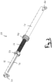
- the present disclosure provides a strut assembly for an external fixation system comprising an elongate first end member, an elongate intermediate member, an elongate second end member, a first adjustment mechanism and a second adjustment mechanism.
- the first end member comprises a first end portion, a second end portion, and a first axial cavity extending from the second end portion.
- the intermediate member comprises a third end portion, a fourth end portion, a second axial cavity extending from the third end portion, and a threaded rod fixedly coupled within the second axial cavity.
- the intermediate member is rotatably fixed and axially translatably within the first axial cavity of the first end member and extends therefrom through the second end portion.
- the second end portion of the first end member comprises external threads
- the first adjustment mechanism comprises an internally threaded first collar member threadably coupled with the external threads of the second end portion, and rotation of the first collar member about the second end portion axially translates the first collar along the second end portion.
- a clamping portion of the first collar member is positioned axially past the second end portion of the first end member and includes a tapered bearing surface
- the first adjustment mechanism further comprises friction member positioned radially between the an exterior surface of a body portion of the intermediate member and the bearing surface.
- the bearing surface comprises a surface that is angled towards the exterior surface of the body portion of the intermediate member as it extends axially away from the second end portion.
- the friction member comprises a deformable ring member.
- the deformable ring member comprises a segmented ring or a split ring.
- the exterior surface of the body portion of the intermediate member comprises a friction-enhancing surface texture.
- the second adjustment mechanism comprises a second collar member axially fixed and rotatably coupled to the fourth end portion of the intermediate member.
- a body portion of second end member includes an axial-extending slot, and the second collar member is rotatably fixed to the second end member via a radially extending second pin that is coupled to the second collar member and is received within the slot of the second end member such that rotation of the second collar member about the fourth end portion axially translates the second end member relative to the intermediate member.
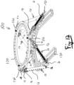
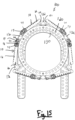
- the first and second platforms 120, 130 may be rings or partial rings such that they extend, at least partially, about an opening and/or an axis (and, potentially, at least partially about bone and/or tissue in situ ).
- a plurality of strut assemblies 10 may be coupled to the first and second platforms 120, 130 about the axis and/or opening thereof.
- the plurality of strut assemblies 10 may be positioned and coupled circumferentially to the first and second platforms 120, 130, and each strut assembly 110 may be attached to the first and second platforms 120, 130 via the first and second joints 22, 24, respectively, at differing positions about the axis and/or opening thereof.
- the strut assemblies 10 may be angled with respect to the axis of first and second platforms 120, 130.
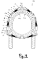
- the strut assembly 10 comprises a second adjustment mechanism configured to selectively rotate the second end member 14 with respect to the intermediate member 16 and the threaded rod 18 to axially translate the second end member 14 relative to the intermediate member 16, and thereby finely adjust the total axial length of the strut assembly 10, as shown in FIGS. 1-7 and 9 .
- the second adjustment mechanism may be provided at an end portion of the intermediate member 16 that is proximate to the second joint 24 (and distal to the first joint 22).
- the engagement portion 52 of the intermediate member 16 includes internal threads, and the threaded rod includes external threads threadably coupled with the internal threads of the engagement portion 52 of the intermediate member 16.
- the engagement portion 52 of the intermediate member 16 includes external threads, and the threaded rod includes internal threads threadably coupled with the external threads of the engagement portion 52 of the intermediate member 16.
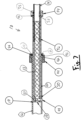
- the second adjustment mechanism comprises a second collar member 54 axially fixed and rotatably coupled to an end portion 53 of the intermediate member 16.
- a first portion of the second collar member 54 may extend over and/or about the end portion 53 of the intermediate member 16 and be rotatably coupled and axially fixed thereto.
- the an inner side of the second collar member 54 and an outer side of the end portion 53 of the intermediate member 16 may include axially aligned circumferential slots or openings and a washer, split ring, O-ring or like member 56 extending therein, as shown in FIGS. 6 , 7 and 9 .
- the washer or ring member 56 may thereby allow the first portion of the second collar member 54 to rotate over the end portion 53 of the intermediate member 16 (about the axis X-X), but prevent the second collar member 54 from axially translating over the end portion 53 of the intermediate member 16 (i.e., translating along the axis X-X).
- a second portion of the second collar member 54 may extend over and/or about the second end member 14 and be rotatably fixed thereto (i.e., fixedly coupled thereto).
- the second portion of the second collar member 54 may be coupled to (or otherwise include) a radially-extending pin member/portion 55.
- the outer surface of the strut body portion of the second end member 14 may include an axially-extending slot 72 that accepts or receives the pin member 55 therein.
- the pin member 55 and the slot 72 are configured such that the pin member 55 is able to axially-translate through/along the axial length of the slot 72.
- the pin member 55 (extending in the pin member 55 and the slot 72 of the second end member) thereby rotatably fixes or fixedly couples the second collar member 54 and the second end member together, but allows the second end member 14 to axially-translate with respect to the pin member 55 and, thereby, the intermediate member 16.
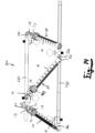
- Rotation of the second collar member 54 over and/or about the second end member 14 thereby causes the second end member 14 to rotate within the cavity of the intermediate member 16 and about the threaded rod 18 (i.e., axially rotate within the cavity with respect to the intermediate member 16 and the threaded rod 18).
- rotation of the second collar member 54 rotates the second end member 14 with respect to the threaded rod 18, which thereby axially translates the second end member 14 relative to the intermediate member 16.
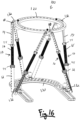
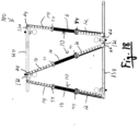
- the axial arrangement of the intermediate member 16 and the second end member 14, and thereby the total axial length of the strut assembly 10 can be easily and quickly finely selected/configured/adjusted by a user via the second collar member 54 (i.e., via rotation of the second collar member 54 about the axis X-X in a particular angular direction), as shown in the arrangements of the strut assemblies 10 of the fixation system 100 in FIGS. 12-16 verse the arrangements of the strut assemblies 10 of the fixation system 100 in FIGS. 16-19 , for example.
Landscapes
- Health & Medical Sciences (AREA)
- Orthopedic Medicine & Surgery (AREA)
- Surgery (AREA)
- Life Sciences & Earth Sciences (AREA)
- Engineering & Computer Science (AREA)
- Medical Informatics (AREA)
- Biomedical Technology (AREA)
- Heart & Thoracic Surgery (AREA)
- Nuclear Medicine, Radiotherapy & Molecular Imaging (AREA)
- Molecular Biology (AREA)
- Animal Behavior & Ethology (AREA)
- General Health & Medical Sciences (AREA)
- Public Health (AREA)
- Veterinary Medicine (AREA)
- General Engineering & Computer Science (AREA)
- Mechanical Engineering (AREA)
- Surgical Instruments (AREA)
Applications Claiming Priority (2)
| Application Number | Priority Date | Filing Date | Title |
|---|---|---|---|
| US201862724462P | 2018-08-29 | 2018-08-29 | |
| PCT/US2019/048931 WO2020047334A1 (en) | 2018-08-29 | 2019-08-29 | Adjustable strut assemblies for external fixation systems |
Publications (4)
| Publication Number | Publication Date |
|---|---|
| EP3843646A1 EP3843646A1 (en) | 2021-07-07 |
| EP3843646A4 EP3843646A4 (en) | 2022-05-04 |
| EP3843646B1 true EP3843646B1 (en) | 2024-07-10 |
| EP3843646C0 EP3843646C0 (en) | 2024-07-10 |
Family
ID=69643075
Family Applications (1)
| Application Number | Title | Priority Date | Filing Date |
|---|---|---|---|
| EP19856041.9A Active EP3843646B1 (en) | 2018-08-29 | 2019-08-29 | Adjustable strut assemblies for external fixation systems |
Country Status (8)
| Country | Link |
|---|---|
| US (3) | US11364054B2 (enExample) |
| EP (1) | EP3843646B1 (enExample) |
| JP (3) | JP7413361B2 (enExample) |
| CN (1) | CN112888388A (enExample) |
| AU (1) | AU2019331007B2 (enExample) |
| BR (1) | BR112021003874A2 (enExample) |
| CA (1) | CA3110684A1 (enExample) |
| WO (1) | WO2020047334A1 (enExample) |
Families Citing this family (7)
| Publication number | Priority date | Publication date | Assignee | Title |
|---|---|---|---|---|
| JP7413361B2 (ja) * | 2018-08-29 | 2024-01-15 | エーエムディーティー ホールディングス インコーポレイテッド | 外固定システムのための調整可能な支柱アセンブリ |
| US11737786B2 (en) | 2019-12-31 | 2023-08-29 | Orthopediatrics Corp. | Multiple track system for positioning of bone segments |
| USD1091822S1 (en) * | 2021-06-23 | 2025-09-02 | DDS Company, Inc. | Fixation article |
| US12496098B2 (en) | 2021-10-18 | 2025-12-16 | A-Fix Inc. | Bone fixator with removable portion |
| US12364510B2 (en) * | 2021-12-20 | 2025-07-22 | Stryker European Operations Limited | Quick release mechanism for strut |
| CN114366261A (zh) * | 2022-01-21 | 2022-04-19 | 中国人民解放军总医院第四医学中心 | 一种髂股牵引分离器 |
| IT202200019140A1 (it) * | 2022-09-19 | 2024-03-19 | Mikai S P A | Dispositivo fissatore esterno per fratture ossee |
Family Cites Families (22)
| Publication number | Priority date | Publication date | Assignee | Title |
|---|---|---|---|---|
| CA2093828A1 (en) * | 1992-04-16 | 1993-10-17 | Anthony Philip Pohl | External bone fixation device |
| US5702196A (en) * | 1996-06-21 | 1997-12-30 | Teleflex, Incorporated | Turnbuckle-type adjustable link |
| EP0933065A1 (de) * | 1998-02-02 | 1999-08-04 | Sulzer Orthopädie AG | Schwenkbares Befestigungssystem an einer Knochenschraube |
| US6030386A (en) * | 1998-08-10 | 2000-02-29 | Smith & Nephew, Inc. | Six axis external fixator strut |
| US6423069B1 (en) * | 1999-03-23 | 2002-07-23 | Synthes (Usa) | Orthopedic system having detachable bone anchors |
| US6908469B2 (en) | 2000-10-04 | 2005-06-21 | Synthes (Usa) | Compact maxillary distractor |
| WO2004026103A2 (en) * | 2002-09-17 | 2004-04-01 | Visionmed, Llc | Unilateral fixator |
| EP2085037B1 (en) * | 2008-02-01 | 2013-07-24 | Stryker Trauma SA | Telescopic strut for an external fixator |
| EP2240085A4 (en) * | 2008-02-08 | 2014-01-01 | Texas Scottish Rite Hospital | EXTERNAL FIXIERSTREBE |
| EP2249721B1 (en) * | 2008-02-12 | 2017-07-05 | Texas Scottish Rite Hospital For Children | Fast adjust external fixation connection rod |
| US8257353B2 (en) * | 2010-02-24 | 2012-09-04 | Wright Medical Technology, Inc. | Orthopedic external fixation device |
| US20130041288A1 (en) * | 2011-08-08 | 2013-02-14 | John Charles Taylor | Apparatus and Method of Monitoring Healing and/or Assessing Mechanical Stiffness of a Bone Fracture Site or the Like |
| US9474552B2 (en) * | 2012-05-04 | 2016-10-25 | Biomet Manufacturing, Llc | Ratcheting strut |
| EP2967669B1 (en) * | 2013-03-13 | 2017-09-13 | DePuy Synthes Products, Inc. | External bone fixation device |
| WO2015136544A1 (en) * | 2014-03-12 | 2015-09-17 | Orthospin Ltd. | Preloaded medical struts |
| US9717528B2 (en) * | 2014-04-01 | 2017-08-01 | Stryker European Holdings I, Llc | External fixator with Y strut |
| TWM503210U (zh) * | 2015-01-06 | 2015-06-21 | Univ Nat Yang Ming | 多軸向顎骨牽引器 |
| US10010350B2 (en) * | 2016-06-14 | 2018-07-03 | Stryker European Holdings I, Llc | Gear mechanisms for fixation frame struts |
| EP3426172B1 (en) * | 2016-07-14 | 2023-06-28 | AMDT Holdings, Inc. | External bone fixation systems |
| GB2556099A (en) * | 2016-11-21 | 2018-05-23 | Caterpillar Energy Solutions Gmbh | Screw tensioning device |
| US10413328B1 (en) * | 2018-03-15 | 2019-09-17 | New Standard Device, LLC | External fixation for the correction of bone deformity and trauma |
| JP7413361B2 (ja) * | 2018-08-29 | 2024-01-15 | エーエムディーティー ホールディングス インコーポレイテッド | 外固定システムのための調整可能な支柱アセンブリ |
-
2019
- 2019-08-29 JP JP2021510910A patent/JP7413361B2/ja active Active
- 2019-08-29 CN CN201980070260.7A patent/CN112888388A/zh active Pending
- 2019-08-29 CA CA3110684A patent/CA3110684A1/en active Pending
- 2019-08-29 EP EP19856041.9A patent/EP3843646B1/en active Active
- 2019-08-29 WO PCT/US2019/048931 patent/WO2020047334A1/en not_active Ceased
- 2019-08-29 AU AU2019331007A patent/AU2019331007B2/en active Active
- 2019-08-29 BR BR112021003874-4A patent/BR112021003874A2/pt active Search and Examination
-
2021
- 2021-02-25 US US17/185,460 patent/US11364054B2/en active Active
-
2022
- 2022-06-17 US US17/807,522 patent/US12232774B2/en active Active
-
2023
- 2023-12-27 JP JP2023220816A patent/JP2024038162A/ja active Pending
-
2025
- 2025-01-16 US US19/024,741 patent/US20250152203A1/en active Pending
- 2025-09-05 JP JP2025147357A patent/JP2025179184A/ja active Pending
Also Published As
| Publication number | Publication date |
|---|---|
| EP3843646A1 (en) | 2021-07-07 |
| US20250152203A1 (en) | 2025-05-15 |
| AU2019331007B2 (en) | 2023-02-16 |
| CA3110684A1 (en) | 2020-03-05 |
| US12232774B2 (en) | 2025-02-25 |
| US20220313316A1 (en) | 2022-10-06 |
| US11364054B2 (en) | 2022-06-21 |
| JP2025179184A (ja) | 2025-12-09 |
| JP2024038162A (ja) | 2024-03-19 |
| EP3843646C0 (en) | 2024-07-10 |
| BR112021003874A2 (pt) | 2021-05-18 |
| CN112888388A (zh) | 2021-06-01 |
| US20210244442A1 (en) | 2021-08-12 |
| EP3843646A4 (en) | 2022-05-04 |
| WO2020047334A1 (en) | 2020-03-05 |
| AU2019331007A1 (en) | 2021-04-08 |
| JP7413361B2 (ja) | 2024-01-15 |
| JP2021536291A (ja) | 2021-12-27 |
Similar Documents
| Publication | Publication Date | Title |
|---|---|---|
| EP3843646B1 (en) | Adjustable strut assemblies for external fixation systems | |
| AU2021286343B2 (en) | External bone fixation systems | |
| US9717528B2 (en) | External fixator with Y strut | |
| EP2789302B1 (en) | Orthopedic external fixation device | |
| EP3245966B1 (en) | Connecting rod for an external fixation device | |
| US12232772B2 (en) | Strut assemblies and external fixation systems | |
| JP2025108785A (ja) | 改善された創外固定支柱 | |
| EP4153076B1 (en) | An orthopaedic device | |
| EP4003198B1 (en) | Intramedullary rod with intrabody outrigger interface | |
| WO2024236158A1 (en) | A bolt for the fixation of bones | |
| CN112074245A (zh) | 用于矫形固定装置的改进的动态化装置 | |
| JP2018061604A (ja) | 骨固定システム |
Legal Events
| Date | Code | Title | Description |
|---|---|---|---|
| STAA | Information on the status of an ep patent application or granted ep patent |
Free format text: STATUS: THE INTERNATIONAL PUBLICATION HAS BEEN MADE |
|
| STAA | Information on the status of an ep patent application or granted ep patent |
Free format text: STATUS: REQUEST FOR EXAMINATION WAS MADE |
|
| PUAI | Public reference made under article 153(3) epc to a published international application that has entered the european phase |
Free format text: ORIGINAL CODE: 0009012 |
|
| 17P | Request for examination filed |
Effective date: 20210325 |
|
| AK | Designated contracting states |
Kind code of ref document: A1 Designated state(s): AL AT BE BG CH CY CZ DE DK EE ES FI FR GB GR HR HU IE IS IT LI LT LU LV MC MK MT NL NO PL PT RO RS SE SI SK SM TR |
|
| DAV | Request for validation of the european patent (deleted) | ||
| DAX | Request for extension of the european patent (deleted) | ||
| A4 | Supplementary search report drawn up and despatched |
Effective date: 20220404 |
|
| RIC1 | Information provided on ipc code assigned before grant |
Ipc: F16B 7/14 20060101ALI20220329BHEP Ipc: A61B 17/62 20060101ALI20220329BHEP Ipc: A61B 17/64 20060101AFI20220329BHEP |
|
| GRAP | Despatch of communication of intention to grant a patent |
Free format text: ORIGINAL CODE: EPIDOSNIGR1 |
|
| STAA | Information on the status of an ep patent application or granted ep patent |
Free format text: STATUS: GRANT OF PATENT IS INTENDED |
|
| RIC1 | Information provided on ipc code assigned before grant |
Ipc: F16B 7/14 20060101ALI20230919BHEP Ipc: A61B 17/62 20060101ALI20230919BHEP Ipc: A61B 17/64 20060101AFI20230919BHEP |
|
| INTG | Intention to grant announced |
Effective date: 20231004 |
|
| GRAJ | Information related to disapproval of communication of intention to grant by the applicant or resumption of examination proceedings by the epo deleted |
Free format text: ORIGINAL CODE: EPIDOSDIGR1 |
|
| STAA | Information on the status of an ep patent application or granted ep patent |
Free format text: STATUS: REQUEST FOR EXAMINATION WAS MADE |
|
| GRAP | Despatch of communication of intention to grant a patent |
Free format text: ORIGINAL CODE: EPIDOSNIGR1 |
|
| STAA | Information on the status of an ep patent application or granted ep patent |
Free format text: STATUS: GRANT OF PATENT IS INTENDED |
|
| INTC | Intention to grant announced (deleted) | ||
| INTG | Intention to grant announced |
Effective date: 20240221 |
|
| GRAS | Grant fee paid |
Free format text: ORIGINAL CODE: EPIDOSNIGR3 |
|
| GRAA | (expected) grant |
Free format text: ORIGINAL CODE: 0009210 |
|
| STAA | Information on the status of an ep patent application or granted ep patent |
Free format text: STATUS: THE PATENT HAS BEEN GRANTED |
|
| AK | Designated contracting states |
Kind code of ref document: B1 Designated state(s): AL AT BE BG CH CY CZ DE DK EE ES FI FR GB GR HR HU IE IS IT LI LT LU LV MC MK MT NL NO PL PT RO RS SE SI SK SM TR |
|
| RAP1 | Party data changed (applicant data changed or rights of an application transferred) |
Owner name: ARTHREX, INC. |
|
| REG | Reference to a national code |
Ref country code: CH Ref legal event code: EP |
|
| REG | Reference to a national code |
Ref country code: DE Ref legal event code: R096 Ref document number: 602019055111 Country of ref document: DE |
|
| U01 | Request for unitary effect filed |
Effective date: 20240806 |
|
| U07 | Unitary effect registered |
Designated state(s): AT BE BG DE DK EE FI FR IT LT LU LV MT NL PT SE SI Effective date: 20240820 |
|
| U20 | Renewal fee for the european patent with unitary effect paid |
Year of fee payment: 6 Effective date: 20240828 |
|
| PG25 | Lapsed in a contracting state [announced via postgrant information from national office to epo] |
Ref country code: NO Free format text: LAPSE BECAUSE OF FAILURE TO SUBMIT A TRANSLATION OF THE DESCRIPTION OR TO PAY THE FEE WITHIN THE PRESCRIBED TIME-LIMIT Effective date: 20241010 |
|
| PG25 | Lapsed in a contracting state [announced via postgrant information from national office to epo] |
Ref country code: GR Free format text: LAPSE BECAUSE OF FAILURE TO SUBMIT A TRANSLATION OF THE DESCRIPTION OR TO PAY THE FEE WITHIN THE PRESCRIBED TIME-LIMIT Effective date: 20241011 Ref country code: PL Free format text: LAPSE BECAUSE OF FAILURE TO SUBMIT A TRANSLATION OF THE DESCRIPTION OR TO PAY THE FEE WITHIN THE PRESCRIBED TIME-LIMIT Effective date: 20240710 |
|
| PG25 | Lapsed in a contracting state [announced via postgrant information from national office to epo] |
Ref country code: IS Free format text: LAPSE BECAUSE OF FAILURE TO SUBMIT A TRANSLATION OF THE DESCRIPTION OR TO PAY THE FEE WITHIN THE PRESCRIBED TIME-LIMIT Effective date: 20241110 |
|
| PG25 | Lapsed in a contracting state [announced via postgrant information from national office to epo] |
Ref country code: HR Free format text: LAPSE BECAUSE OF FAILURE TO SUBMIT A TRANSLATION OF THE DESCRIPTION OR TO PAY THE FEE WITHIN THE PRESCRIBED TIME-LIMIT Effective date: 20240710 |
|
| PG25 | Lapsed in a contracting state [announced via postgrant information from national office to epo] |
Ref country code: ES Free format text: LAPSE BECAUSE OF FAILURE TO SUBMIT A TRANSLATION OF THE DESCRIPTION OR TO PAY THE FEE WITHIN THE PRESCRIBED TIME-LIMIT Effective date: 20240710 Ref country code: RS Free format text: LAPSE BECAUSE OF FAILURE TO SUBMIT A TRANSLATION OF THE DESCRIPTION OR TO PAY THE FEE WITHIN THE PRESCRIBED TIME-LIMIT Effective date: 20241010 |
|
| PG25 | Lapsed in a contracting state [announced via postgrant information from national office to epo] |
Ref country code: RS Free format text: LAPSE BECAUSE OF FAILURE TO SUBMIT A TRANSLATION OF THE DESCRIPTION OR TO PAY THE FEE WITHIN THE PRESCRIBED TIME-LIMIT Effective date: 20241010 Ref country code: PL Free format text: LAPSE BECAUSE OF FAILURE TO SUBMIT A TRANSLATION OF THE DESCRIPTION OR TO PAY THE FEE WITHIN THE PRESCRIBED TIME-LIMIT Effective date: 20240710 Ref country code: NO Free format text: LAPSE BECAUSE OF FAILURE TO SUBMIT A TRANSLATION OF THE DESCRIPTION OR TO PAY THE FEE WITHIN THE PRESCRIBED TIME-LIMIT Effective date: 20241010 Ref country code: IS Free format text: LAPSE BECAUSE OF FAILURE TO SUBMIT A TRANSLATION OF THE DESCRIPTION OR TO PAY THE FEE WITHIN THE PRESCRIBED TIME-LIMIT Effective date: 20241110 Ref country code: HR Free format text: LAPSE BECAUSE OF FAILURE TO SUBMIT A TRANSLATION OF THE DESCRIPTION OR TO PAY THE FEE WITHIN THE PRESCRIBED TIME-LIMIT Effective date: 20240710 Ref country code: GR Free format text: LAPSE BECAUSE OF FAILURE TO SUBMIT A TRANSLATION OF THE DESCRIPTION OR TO PAY THE FEE WITHIN THE PRESCRIBED TIME-LIMIT Effective date: 20241011 Ref country code: ES Free format text: LAPSE BECAUSE OF FAILURE TO SUBMIT A TRANSLATION OF THE DESCRIPTION OR TO PAY THE FEE WITHIN THE PRESCRIBED TIME-LIMIT Effective date: 20240710 |
|
| REG | Reference to a national code |
Ref country code: CH Ref legal event code: PL |
|
| PG25 | Lapsed in a contracting state [announced via postgrant information from national office to epo] |
Ref country code: SM Free format text: LAPSE BECAUSE OF FAILURE TO SUBMIT A TRANSLATION OF THE DESCRIPTION OR TO PAY THE FEE WITHIN THE PRESCRIBED TIME-LIMIT Effective date: 20240710 |
|
| PG25 | Lapsed in a contracting state [announced via postgrant information from national office to epo] |
Ref country code: MC Free format text: LAPSE BECAUSE OF FAILURE TO SUBMIT A TRANSLATION OF THE DESCRIPTION OR TO PAY THE FEE WITHIN THE PRESCRIBED TIME-LIMIT Effective date: 20240710 Ref country code: CH Free format text: LAPSE BECAUSE OF NON-PAYMENT OF DUE FEES Effective date: 20240831 |
|
| PG25 | Lapsed in a contracting state [announced via postgrant information from national office to epo] |
Ref country code: CZ Free format text: LAPSE BECAUSE OF FAILURE TO SUBMIT A TRANSLATION OF THE DESCRIPTION OR TO PAY THE FEE WITHIN THE PRESCRIBED TIME-LIMIT Effective date: 20240710 |
|
| PG25 | Lapsed in a contracting state [announced via postgrant information from national office to epo] |
Ref country code: SK Free format text: LAPSE BECAUSE OF FAILURE TO SUBMIT A TRANSLATION OF THE DESCRIPTION OR TO PAY THE FEE WITHIN THE PRESCRIBED TIME-LIMIT Effective date: 20240710 |
|
| PLBE | No opposition filed within time limit |
Free format text: ORIGINAL CODE: 0009261 |
|
| STAA | Information on the status of an ep patent application or granted ep patent |
Free format text: STATUS: NO OPPOSITION FILED WITHIN TIME LIMIT |
|
| 26N | No opposition filed |
Effective date: 20250411 |
|
| PG25 | Lapsed in a contracting state [announced via postgrant information from national office to epo] |
Ref country code: IE Free format text: LAPSE BECAUSE OF NON-PAYMENT OF DUE FEES Effective date: 20240829 |
|
| U20 | Renewal fee for the european patent with unitary effect paid |
Year of fee payment: 7 Effective date: 20250709 |
|
| PGFP | Annual fee paid to national office [announced via postgrant information from national office to epo] |
Ref country code: GB Payment date: 20250703 Year of fee payment: 7 |
|
| PG25 | Lapsed in a contracting state [announced via postgrant information from national office to epo] |
Ref country code: RO Free format text: LAPSE BECAUSE OF FAILURE TO SUBMIT A TRANSLATION OF THE DESCRIPTION OR TO PAY THE FEE WITHIN THE PRESCRIBED TIME-LIMIT Effective date: 20240710 |