EP3843595B1 - Adjustable additive delivery systems and dispensing closure valves for the same - Google Patents
Adjustable additive delivery systems and dispensing closure valves for the same Download PDFInfo
- Publication number
- EP3843595B1 EP3843595B1 EP19854883.6A EP19854883A EP3843595B1 EP 3843595 B1 EP3843595 B1 EP 3843595B1 EP 19854883 A EP19854883 A EP 19854883A EP 3843595 B1 EP3843595 B1 EP 3843595B1
- Authority
- EP
- European Patent Office
- Prior art keywords
- valve
- closure
- base
- additive
- delivery system
- Prior art date
- Legal status (The legal status is an assumption and is not a legal conclusion. Google has not performed a legal analysis and makes no representation as to the accuracy of the status listed.)
- Active
Links
Images


Classifications
-
- B—PERFORMING OPERATIONS; TRANSPORTING
- B01—PHYSICAL OR CHEMICAL PROCESSES OR APPARATUS IN GENERAL
- B01F—MIXING, e.g. DISSOLVING, EMULSIFYING OR DISPERSING
- B01F35/00—Accessories for mixers; Auxiliary operations or auxiliary devices; Parts or details of general application
- B01F35/80—Forming a predetermined ratio of the substances to be mixed
- B01F35/83—Forming a predetermined ratio of the substances to be mixed by controlling the ratio of two or more flows, e.g. using flow sensing or flow controlling devices
-
- A—HUMAN NECESSITIES
- A47—FURNITURE; DOMESTIC ARTICLES OR APPLIANCES; COFFEE MILLS; SPICE MILLS; SUCTION CLEANERS IN GENERAL
- A47J—KITCHEN EQUIPMENT; COFFEE MILLS; SPICE MILLS; APPARATUS FOR MAKING BEVERAGES
- A47J31/00—Apparatus for making beverages
- A47J31/005—Portable or compact beverage making apparatus, e.g. for travelling, for use in automotive vehicles
-
- A—HUMAN NECESSITIES
- A47—FURNITURE; DOMESTIC ARTICLES OR APPLIANCES; COFFEE MILLS; SPICE MILLS; SUCTION CLEANERS IN GENERAL
- A47J—KITCHEN EQUIPMENT; COFFEE MILLS; SPICE MILLS; APPARATUS FOR MAKING BEVERAGES
- A47J31/00—Apparatus for making beverages
- A47J31/40—Beverage-making apparatus with dispensing means for adding a measured quantity of ingredients, e.g. coffee, water, sugar, cocoa, milk, tea
- A47J31/401—Beverage-making apparatus with dispensing means for adding a measured quantity of ingredients, e.g. coffee, water, sugar, cocoa, milk, tea whereby the powder ingredients and the water are delivered to a mixing bowl
-
- A—HUMAN NECESSITIES
- A47—FURNITURE; DOMESTIC ARTICLES OR APPLIANCES; COFFEE MILLS; SPICE MILLS; SUCTION CLEANERS IN GENERAL
- A47J—KITCHEN EQUIPMENT; COFFEE MILLS; SPICE MILLS; APPARATUS FOR MAKING BEVERAGES
- A47J31/00—Apparatus for making beverages
- A47J31/40—Beverage-making apparatus with dispensing means for adding a measured quantity of ingredients, e.g. coffee, water, sugar, cocoa, milk, tea
- A47J31/41—Beverage-making apparatus with dispensing means for adding a measured quantity of ingredients, e.g. coffee, water, sugar, cocoa, milk, tea of liquid ingredients
-
- A—HUMAN NECESSITIES
- A47—FURNITURE; DOMESTIC ARTICLES OR APPLIANCES; COFFEE MILLS; SPICE MILLS; SUCTION CLEANERS IN GENERAL
- A47J—KITCHEN EQUIPMENT; COFFEE MILLS; SPICE MILLS; APPARATUS FOR MAKING BEVERAGES
- A47J31/00—Apparatus for making beverages
- A47J31/44—Parts or details or accessories of beverage-making apparatus
- A47J31/46—Dispensing spouts, pumps, drain valves or like liquid transporting devices
- A47J31/461—Valves, e.g. drain valves
-
- A—HUMAN NECESSITIES
- A47—FURNITURE; DOMESTIC ARTICLES OR APPLIANCES; COFFEE MILLS; SPICE MILLS; SUCTION CLEANERS IN GENERAL
- A47J—KITCHEN EQUIPMENT; COFFEE MILLS; SPICE MILLS; APPARATUS FOR MAKING BEVERAGES
- A47J43/00—Implements for preparing or holding food, not provided for in other groups of this subclass
- A47J43/27—Implements for preparing or holding food, not provided for in other groups of this subclass for mixing drinks; Hand-held shakers
-
- B—PERFORMING OPERATIONS; TRANSPORTING
- B01—PHYSICAL OR CHEMICAL PROCESSES OR APPARATUS IN GENERAL
- B01F—MIXING, e.g. DISSOLVING, EMULSIFYING OR DISPERSING
- B01F23/00—Mixing according to the phases to be mixed, e.g. dispersing or emulsifying
- B01F23/40—Mixing liquids with liquids; Emulsifying
- B01F23/45—Mixing liquids with liquids; Emulsifying using flow mixing
- B01F23/451—Mixing liquids with liquids; Emulsifying using flow mixing by injecting one liquid into another
-
- B—PERFORMING OPERATIONS; TRANSPORTING
- B01—PHYSICAL OR CHEMICAL PROCESSES OR APPARATUS IN GENERAL
- B01F—MIXING, e.g. DISSOLVING, EMULSIFYING OR DISPERSING
- B01F25/00—Flow mixers; Mixers for falling materials, e.g. solid particles
- B01F25/105—Mixing heads, i.e. compact mixing units or modules, using mixing valves for feeding and mixing at least two components
-
- B—PERFORMING OPERATIONS; TRANSPORTING
- B01—PHYSICAL OR CHEMICAL PROCESSES OR APPARATUS IN GENERAL
- B01F—MIXING, e.g. DISSOLVING, EMULSIFYING OR DISPERSING
- B01F33/00—Other mixers; Mixing plants; Combinations of mixers
- B01F33/50—Movable or transportable mixing devices or plants
- B01F33/501—Movable mixing devices, i.e. readily shifted or displaced from one place to another, e.g. portable during use
- B01F33/5011—Movable mixing devices, i.e. readily shifted or displaced from one place to another, e.g. portable during use portable during use, e.g. hand-held
- B01F33/50111—Small portable bottles, flasks, vials, e.g. with means for mixing ingredients or for homogenizing their content, e.g. by hand shaking
-
- B—PERFORMING OPERATIONS; TRANSPORTING
- B01—PHYSICAL OR CHEMICAL PROCESSES OR APPARATUS IN GENERAL
- B01F—MIXING, e.g. DISSOLVING, EMULSIFYING OR DISPERSING
- B01F35/00—Accessories for mixers; Auxiliary operations or auxiliary devices; Parts or details of general application
- B01F35/71—Feed mechanisms
- B01F35/716—Feed mechanisms characterised by the relative arrangement of the containers for feeding or mixing the components
- B01F35/7162—A container being placed inside the other before contacting the contents
-
- B—PERFORMING OPERATIONS; TRANSPORTING
- B01—PHYSICAL OR CHEMICAL PROCESSES OR APPARATUS IN GENERAL
- B01F—MIXING, e.g. DISSOLVING, EMULSIFYING OR DISPERSING
- B01F35/00—Accessories for mixers; Auxiliary operations or auxiliary devices; Parts or details of general application
- B01F35/71—Feed mechanisms
- B01F35/717—Feed mechanisms characterised by the means for feeding the components to the mixer
- B01F35/71795—Squeezing a flexible container
-
- B—PERFORMING OPERATIONS; TRANSPORTING
- B01—PHYSICAL OR CHEMICAL PROCESSES OR APPARATUS IN GENERAL
- B01F—MIXING, e.g. DISSOLVING, EMULSIFYING OR DISPERSING
- B01F35/00—Accessories for mixers; Auxiliary operations or auxiliary devices; Parts or details of general application
- B01F35/71—Feed mechanisms
- B01F35/717—Feed mechanisms characterised by the means for feeding the components to the mixer
- B01F35/718—Feed mechanisms characterised by the means for feeding the components to the mixer using vacuum, under pressure in a closed receptacle or circuit system
-
- B—PERFORMING OPERATIONS; TRANSPORTING
- B65—CONVEYING; PACKING; STORING; HANDLING THIN OR FILAMENTARY MATERIAL
- B65D—CONTAINERS FOR STORAGE OR TRANSPORT OF ARTICLES OR MATERIALS, e.g. BAGS, BARRELS, BOTTLES, BOXES, CANS, CARTONS, CRATES, DRUMS, JARS, TANKS, HOPPERS, FORWARDING CONTAINERS; ACCESSORIES, CLOSURES, OR FITTINGS THEREFOR; PACKAGING ELEMENTS; PACKAGES
- B65D25/00—Details of other kinds or types of rigid or semi-rigid containers
- B65D25/02—Internal fittings
- B65D25/04—Partitions
- B65D25/08—Partitions with provisions for removing or destroying, e.g. to facilitate mixing of contents
-
- B—PERFORMING OPERATIONS; TRANSPORTING
- B65—CONVEYING; PACKING; STORING; HANDLING THIN OR FILAMENTARY MATERIAL
- B65D—CONTAINERS FOR STORAGE OR TRANSPORT OF ARTICLES OR MATERIALS, e.g. BAGS, BARRELS, BOTTLES, BOXES, CANS, CARTONS, CRATES, DRUMS, JARS, TANKS, HOPPERS, FORWARDING CONTAINERS; ACCESSORIES, CLOSURES, OR FITTINGS THEREFOR; PACKAGING ELEMENTS; PACKAGES
- B65D47/00—Closures with filling and discharging, or with discharging, devices
- B65D47/04—Closures with discharging devices other than pumps
- B65D47/06—Closures with discharging devices other than pumps with pouring spouts or tubes; with discharge nozzles or passages
- B65D47/12—Closures with discharging devices other than pumps with pouring spouts or tubes; with discharge nozzles or passages having removable closures
- B65D47/14—Closures with discharging devices other than pumps with pouring spouts or tubes; with discharge nozzles or passages having removable closures and closure-retaining means
- B65D47/147—Closures with discharging devices other than pumps with pouring spouts or tubes; with discharge nozzles or passages having removable closures and closure-retaining means for snap-on caps
- B65D47/148—Closures with discharging devices other than pumps with pouring spouts or tubes; with discharge nozzles or passages having removable closures and closure-retaining means for snap-on caps with internal parts
-
- B—PERFORMING OPERATIONS; TRANSPORTING
- B65—CONVEYING; PACKING; STORING; HANDLING THIN OR FILAMENTARY MATERIAL
- B65D—CONTAINERS FOR STORAGE OR TRANSPORT OF ARTICLES OR MATERIALS, e.g. BAGS, BARRELS, BOTTLES, BOXES, CANS, CARTONS, CRATES, DRUMS, JARS, TANKS, HOPPERS, FORWARDING CONTAINERS; ACCESSORIES, CLOSURES, OR FITTINGS THEREFOR; PACKAGING ELEMENTS; PACKAGES
- B65D47/00—Closures with filling and discharging, or with discharging, devices
- B65D47/04—Closures with discharging devices other than pumps
- B65D47/20—Closures with discharging devices other than pumps comprising hand-operated members for controlling discharge
- B65D47/2018—Closures with discharging devices other than pumps comprising hand-operated members for controlling discharge comprising a valve or like element which is opened or closed by deformation of the container or closure
- B65D47/2031—Closures with discharging devices other than pumps comprising hand-operated members for controlling discharge comprising a valve or like element which is opened or closed by deformation of the container or closure the element being formed by a slit, narrow opening or constrictable spout, the size of the outlet passage being able to be varied by increasing or decreasing the pressure
-
- B—PERFORMING OPERATIONS; TRANSPORTING
- B01—PHYSICAL OR CHEMICAL PROCESSES OR APPARATUS IN GENERAL
- B01F—MIXING, e.g. DISSOLVING, EMULSIFYING OR DISPERSING
- B01F25/00—Flow mixers; Mixers for falling materials, e.g. solid particles
- B01F2025/91—Direction of flow or arrangement of feed and discharge openings
- B01F2025/917—Laminar or parallel flow, i.e. every point of the flow moves in layers which do not intermix
-
- B—PERFORMING OPERATIONS; TRANSPORTING
- B01—PHYSICAL OR CHEMICAL PROCESSES OR APPARATUS IN GENERAL
- B01F—MIXING, e.g. DISSOLVING, EMULSIFYING OR DISPERSING
- B01F2101/00—Mixing characterised by the nature of the mixed materials or by the application field
- B01F2101/06—Mixing of food ingredients
- B01F2101/14—Mixing of ingredients for non-alcoholic beverages; Dissolving sugar in water
Definitions
- the disclosure relates to dispensing and delivery systems for beverages and other products and more particularly to dispensing and delivery systems in which an additive, such as flavorings, concentrates or supplements, may be provided in replaceable, modular cartridges, which may include features for mixing the additive with a base liquid, such as water, as the base liquid flows through the cartridge and is consumed by a user.
- the disclosure further relates to dispensing and delivery systems and additive delivery systems that provide for user adjustment of the amount of additive that is mixed with the base liquid.
- the disclosure further relates to dispensing closures and dispensing closure valves and to mixing cartridges and additive storage and delivery systems and devices that may include such dispensing closure valves.
- Such systems may mix additive with base liquid as the base liquid flows through the mixing cartridge and thereby add flavor to the base liquid as a user draws the mixture and through the cartridge.
- Such systems may include a one-way valve to prevent backflow of base liquid through the cartridge, thus maintaining a supply of base liquid in an unmixed state.
- the cartridge may have defined therein, upstream from the one-way valve, a mixing zone or mixing section, which may be a defined volume within the cartridge where the additive is added to and mixed with the base liquid.
- a push-pull cap closure may be employed for permitting a user to selectively dispense mixed liquid from the dispenser or close the dispenser by snapping the push-pull cap in a closed position.
- Such closures may be cumbersome to some users since the opening operation typically requires two-hand operation - one hand to hold the container and another to pull the closure open.
- such closures do not facilitate a quick termination of flow when contents are dispensed, leaving the possibility for dripping of contents after a user takes a sip, which is undesirable.
- closures may not be ideal for dispensing for all users, may tend to have somewhat restricted flow, and may be undesirable when higher flow rates and volumes of dispensed liquid are desired by a user.
- US 2001/025859 A1 discloses a dispensing container which stored two or more separated fluids and blends the fluids when dispensing.
- WO 2017/152192 A1 discloses an adjustable additive cartridge system, including a contained cap and a reservoir assembly that provides for storage of an additive.
- the container cap includes a mixing nozzle and a one-way valve..
- an additive delivery system includes a dispensing closure valve to provide improved control of residual mixed liquid in the mixing zone or mixing section of the delivery system and may provide improved flow and dispensing characteristics.
- the dispensing closure valve includes a closure base having a valve retainer interlock for securing a valve retainer thereto.
- the valve includes a slit valve configuration and is held in place on the closure base with the valve retainer.
- the closure base may include a lid tethered thereto for sealingly engaging the valve retainer and sealing the closure.
- the dispensing closure valve may provide improved flow and dispensing characteristics as mixture is dispensed from the cartridge.
- the dispensing closure valve may prevent the discharge of, and may contain residual mixed liquid within a mixing section of the cartridge when the cartridge is not in use by a user.
- the dispensing closure valve interacts with a base liquid flow valve to provide improved flow and control characteristics.
- the combination of a one-way base liquid flow valve and the dispensing closure valve, with a mixing section defined therebetween, has been discovered by applicant to produce desirable flow characteristics. More specifically, the configuration exhibits a constant proportional relationship between suction pressure and flow rate within a suction pressure range that may typically be applied by a user.
- the dispensing closure valve is provided in a cartridge environment that includes a flow controlling structure in the cartridge spout. More specifically, the cartridge spout may include a button-shaped projection supported by radial spokes and radial flow passages. The valve membrane of the dispensing closure valve interacts with this structure to achieve desirable flow characteristics.
- the dispensing closure may facilitate one-hand operation for opening a lid.
- a tethering strap may connect the lid to the closure base and be configured to undertake a bowed configuration when the lid is installed on the closure base. Lateral force applied to the tethering strap produces an upward force on the lid, allowing a user to remove the lid by pressing on the tethering strap with a thumb or finger.
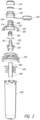
- An example mixing cartridge or additive delivery system environment 100 may include a number of components for facilitating adjustable mixing of additive (flavoring) with a base liquid (water) as the base liquid flows through the cartridge.
- the components may be assembled in a generally stacked arrangement using snap-fit or threaded connections that facilitate quick assembly.
- the components may include a cartridge cap comprising an additive flow adjustment actuator 200 cooperating with and mounted for limited rotational movement relative to a cartridge cap base 250.
- Additive flow adjustment actuator 200 may include a main body 202 and an actuator dispensing spout 206 extending upward therefrom and defining an interior flow passage for mixed liquid dispensed from the cartridge.
- a number of radial flow passages 208 may be defined between a number of radial spokes that support a button-shaped central projection 209 (see FIGS. 13 and 14 , as well).
- a spout cap retaining projection 211 may extend around the outer circumference of an upper area of the spout 206. This general spout configuration may be adapted to receive a push-pull cap to selectively seal or open the spout.
- An additive reservoir assembly may be disposed on the underside the cap base 250 and may include a reservoir spout 400 having a flexible pouch (not shown) secured thereto (i.e., by welded seam to fitment 402 for containing a supply of additive.
- a reservoir housing 500 may surround the reservoir spout and pouch and may be secured to the reservoir spout.
- the reservoir protective housing 500 which may be a cage or a solid-walled (illustrated) cover, may be snap-fit to one or more flanges 404 on the pouch reservoir spout 400.
- the reservoir housing 500 and reservoir pouch may be made of a transparent or translucent material to permit a user to view and identify the nature of the additive supply.
- a mixing nozzle 350 may extend from the top of the cap base 250.
- the mixing nozzle 350 may include a threaded mixing nozzle stem 360 that includes integral threads 362 on an exterior surface thereof.
- the mixing nozzle 350 defines at least a portion of an additive flow path by way of an internal mixing nozzle additive flow passage 363 extending through the mixing nozzle stem 360.
- a bottom portion of the mixing nozzle 350 may receive the reservoir spout 400 thus providing for the flow of additive from the reservoir through the central passage 363.
- a plurality of radially arranged base liquid ports 358 may be defined in the mixing nozzle 350 to permit flow of base liquid and at least partially define a base liquid flow path through the mixing nozzle 350.
- An annular one-way base liquid flow valve 320 may be secured to the mixing nozzle 350 in a position where it provides for one-way flow of base liquid through the base liquid ports 358 and prevents backflow therethrough (see FIG. 9 ).
- the mixing nozzle 350 defines parts of a base liquid flow path and part of an additive flow path therein. More particularly, the additive flow path is partially defined by a centrally or axially located passage 363 in the mixing nozzle, while the base liquid flow path includes the plural base liquid ports 358 that are disposed outward from the central location at least partially surrounding the additive liquid flow path. This flow geometry provides advantageous mixing and flow characteristics as further described in the above related applications.
- an additive flow metering component 300 Disposed between the additive flow adjustment actuator 200 and cartridge cap base 250 is an additive flow metering component 300, which cooperates with a mixing nozzle 350 to provide for adjustable mixture of additive with the base liquid.
- a conical seat on an upper portion of the mixing nozzle 350 cooperates with a conical surface on the metering component 300.
- User rotation of the actuator 200 relative to the cap base 250 will rotate the metering component 300 relative to the mixing nozzle spout 360 and, by way of threads 362, will permit a user to adjust the space between the conical surface on the metering component 300 and the conical seat on the mixing nozzle 350, which in turn, will adjust the flow of additive introduced into the base liquid as it flows through the cartridge.
- a number of axially extending guide rails 216 are defined on an interior of the spout portion 206 and define guide channels therebetween, which cooperate with and guide complementarily-shaped guide elements 316 on additive flow metering component 300 and allow it to slide upward or downward relative to the actuator 200 when the actuator 200 is rotated.
- the additive flow adjustment actuator may be rotated relative to the cap base 250. Such rotation causes rotation of the metering component/insert 300 relative to the mixing nozzle 350, resulting in slight axial, i.e., upward or downward movement of the insert 300 by way of the cooperating threads between the insert 300 and nozzle 350. Axial movement of the metering insert 300 results in a change of additive flow through the metering area between the conical portion of insert 300 and the corresponding surface on mixing nozzle 350.
- base liquid flows into the cartridge assembly, resulting from pressure changes within the base liquid container, i.e., from squeezing of a flexible bottle and/or by suction applied by a user during consumption, and/or inverting or tipping, such action results in flow of additive, and base liquid is mixed with additive at the appropriate level determined by the rotational position of the additive flow adjustment actuator.
- a residual mixture in a mixing section or zone in the cartridge may be defined between the base liquid flow valve 320 and the exit passage of the spout 206.
- this space may be occupied by mixed residual liquid.
- the base liquid flow valve 320 prevents backflow of the mixed liquid back through the cartridge.
- the residual liquid in the mixing section or zone may be prone to drip upon the next dispensing operation (sip) by the user.
- the use of a push-pull closure on the spout 206 may compress the residual liquid in the mixing section or zone, causing undesirable drip or discharge.
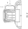
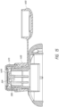
- An example dispensing closure valve assembly 600 may include a closure base 630, a lid 650, a valve retainer 670 and valve 690. Details of each of these components and their operation will next be described.
- Closure base 630 may include an annular spout-engaging skirt 632 having a tapered inner lower surface 634 to facilitate quick alignment/installation on the spout 206, for example ( FIGS. 1 and 2 ).
- a closure base spout 636 may extend upward from the skirt 632 to a valve retaining end 638.
- Closure base 630 may have a valve retainer interlock 640 for engaging and securing the valve retainer 670 ( FIGS. 1 , 2 , 5 and 6 ) on the closure base 630.
- Interlock 640 may include an annular retainer securing groove or recess 642 formed in an upper portion of the closure skirt 632 and extending concentrically around a lower portion of the closure base spout 636.
- One or more annular interlock recesses or grooves 644 may be included in the retainer securing groove or recess 642 for providing a friction or interference fit with complimentary elements on the valve retainer 670 ( FIG. 1 ) to secure the valve retainer to the closure base 630.
- Valve retaining end 638 of the closure base spout 636 may include a land or sealing surface 639 and an annular shoulder 633 both for engaging and/or supporting the valve 690 ( FIGS. 1 and 2 ) as will be explained further below.
- the land or sealing surface 639 may have a slightly inclined orientation, extending upward and radially inward, such that a well-defined circumferential edge or lip 637 is provided to engage an underside of the valve 690. This permits close control of the valve sealing and performance characteristics.
- a spout post engaging bead or ridge 635 may be formed on the interior surface of the closure base spout 636 to secure the closure base 630 to the spout post 206 by forming an interference fit with a counterpart ridge or bead 211 ( FIGS. 1 and 14 ) on the spout post 206.
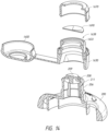
- Closure base 630 may include a lid 650 connected thereto via a tethering strap 652. Tethering strap may also function as a lid release assist feature to enable one-hand removal of the lid 650 from a closed position on the retainer 670, as will be described.
- Closure base 630, lid 650 and tethering strap may be formed integrally as a unitary piece from a suitable thermoplastic, such as polypropylene.
- Lid 650 may include an annular lid wall 654 extending from a lid end wall 655.
- a lid sealing ring 656 may extend from the lid wall 654 and provide sealing engagement with the valve and/or retainer, as will be described.
- Lid 650 may have a number of lid interlock projections 657 extending from an upper, inner surface lid wall 654.
- Interlock projections 657 may engage one or more grooves or other complimentarily shaped elements on the valve retainer 670 to secure the lid 650 in place thereon.
- Lid wall 654 may include an annular gripping projection 658 to permit a user to easily remove the lid 650 in a one-hand operation, i.e., by prying it with the user's thumb.
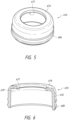
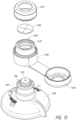
- FIGS. 5 and 6 illustrate an example valve retainer 670 according to aspects of the disclosure.
- An annular valve retainer wall 672 extends upward to an inwardly projecting valve retaining ledge 674 with a valve sealing interface defined on the underside thereof for engaging the valve.
- the valve sealing interface may have an inner lip 677 and a tapered, undercut portion 679 to ensure that the valve surface is sufficiently engaged by the inner lip 677. That is, when the retainer 670 is secured to the cap base 630, the inner lip 677 will apply a concentrated, localized sealing force on the valve along a well-defined perimeter coinciding with the diameter of the annular inner lip 677. As will be recognized, the inner lip 677 in conjunction with the lip or edge 637 on the valve land 639 ( FIG.
- the outer annular surface of the valve retainer wall 672 may include an annular retaining projection 680 which cooperates with the interlock 640 ( FIG. 4 ) on the closure cap 630.
- An annular lid retaining projection may also extend around the perimeter of the valve retainer wall 672 and cooperate with the lid interlock projections 657 ( FIG. 4 ) to retain the lid 650 on the valve retainer 670.
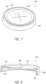
- FIGS. 7 and 8 illustrate an example valve 690 according to an aspect of the disclosure.
- Valve 690 may include an annular valve skirt or wall 692 and a valve membrane 694 extending across the skirt 692.
- Valve 690 may include one or more valve passages 696 defined therein.
- the valve passage has a slit configuration with two generally orthogonal slits being formed or being cut in the membrane 694.
- Other slit configurations are contemplated, including parallel slits or partial concentric or circumferential slits.
- other passage forms besides slits are contemplated, including perforations of circular or other shapes.
- the thickness of membrane 694, the configuration of the slits or passages 696, the material and associated resiliency of the membrane and other attributes may be selected to provide suitable flow and pressure characteristic for the valve. Applicant has found that favorable flow characteristics may be achieved with the use of Shore 50A food grade silicone for the valve membrane with a thickness of about 0.45 mm and slit configuration of two orthogonal slits, each having a length (diametrical) of about 11 mm. Further, a valve circumferential lip (637 in FIG. 4 ) and valve retainer inner lip (677 in FIG. 6 ) diameter of about 12 mm in combination with the above-described valve configuration may provide favorable flow characteristics and control of liquid in the mixing section.
- Valve skirt 692 may include a tapered lower surface 698 to facilitate quick and/or automated assembly on the closure base 630.
- Opposed tapered surfaces 697 and 695 may extend at an angle of about 23 degrees to one another and may be provided for a complimentary fit with the corresponding surfaces on the closure base land 639 ( FIG. 4 ) and the valve retainer 670.
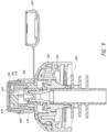
- FIG. 9 is a cross-section showing the dispensing closure 600 and constituent components assembled in an additive delivery system environment.
- the valve membrane may extend across the top of the spout post, with the slits oriented in a particular way relative to the spout structure. It will be recognized that a residual mixture volume, mixing zone or mixing section may be defined within the assembly between the base liquid flow seal 320 and the mixture dispensing valve 690. Applicant has discovered that favorable flow and mixing characteristics and uniformity of flavor may be achieved by the combination of the described dispensing closure valve and the base liquid valve situated in the described configuration.
- the actuator spout 206 and the specific flow characteristics of the spout, including the radial spokes and intervening radial flow passages therebetween as well as the button shaped projection thereon may provide desirable flow characteristics when combined with the dispensing closure valve 600. More specifically, the radial flow passages may guide respective streams of mixed liquid to particular local areas of the valve membrane and impinge each "sector" defined by the slits in the same way. Moreover, the button-shaped projection prevents flow in the central area of the valve membrane, i.e., where the slits intersect, where the membrane provides less resistance to flow. This interaction may thereby provide a more consistent and predictable stream of liquid dispensed through the closure dispensing valve.
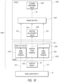
- FIG. 10 is a schematic illustration of the additive delivery systems and constituent components contemplated by the instant disclosure.
- the additive delivery system is generally represented by the reference number 1000.
- multiple base liquid flow paths 10.1 and 10.3 may be defined by virtue of multiple flow passages, such as passages 358 ( FIG. 1 ) in the mixing nozzle 350, which may be in a radial pattern around a central additive flow passage 1363.
- a base liquid flow valve 1320 which provides only one-way flow and prevents backflow of the base liquid, may be associated with each of the base liquid flow paths, as for example, the seal 320 in FIG. 1 .
- base liquid flow paths 10.1, 10.2, 10.3 and 10.4 are defined from the base liquid supply 10, through base liquid passages 1352 in the base 1250, through the base liquid flow valve 1320 to the mixing section 1240.
- An additive flow path 20.1 and 20.2 is defined from the additive supply 20 through an additive flow passage 1363 in the base 1250, through additive adjustment valve 1300 to a mixing section 1240.
- a mixed liquid flow path 30 is defined through the mixing section to the closure dispensing valve 1600.
- additive adjustment valve and additive flow passage elements are illustrated as being disposed in the spout or in the base, their location may be modified and/or interchanged with or to other components in the system within the scope of the disclosure. Similarly, the position and relative orientation of flow paths for the base liquid and the additive may be modified without departing from the scope of the disclosure.
- FIG. 11 is a graphical representation of pressure (suction) and flow characteristics for additive delivery systems according to aspects of the disclosure.
- FIG. 11 also depicts, as the curve 1110, pressure and flow characteristics for dispensing closure valves in isolation (i.e., not combined with the environments described herein) for systems in which only a one-way base liquid valve is provided.
- Curve 1120 represents pressure and flow characteristics of a dispensing closure valve as described herein in isolation (i.e., not combined with the environments described herein).
- the interaction of the dispensing closure valve and the base liquid flow valve in the described environments may provide improved mixture flow characteristics.
- curve 1100 shows, from about 482 Pa (0.07 psi) to about 2068 Pa (0.3 psi), a substantially constant proportional (linear) relationship between the flow rate, from 0.0 to about 10.5 ml/s.
- the flow and pressure characteristics of the isolated dispensing closure valve and isolated base liquid valve exhibit variances in flow rate proportion within the same range.
- the flow rate for the dispensing closure valve is preferably selected to be higher than the flow rate for the base liquid valve at most pressures.
- the dispensing closure valve should be configured to have less impact on flow than the base liquid flow valve.
- the base liquid valve may provide higher threshold pressure for any flow of base liquid to occur and may be configured to prevent flow at the expected pressure on the base liquid valve that may coincide with full inverted base liquid container so as to prevent flow of base liquid when a water bottle is inverted but no suction pressure is applied to the dispensing closure valve. This will isolate the mixing section from the static pressure of the inverted supply of base liquid in the container.
- dispensing closure valve to be configured to a lower threshold pressure in order to prevent flow from the mixing section of the cartridge when inverted but without suction applied to the dispensing closure valve, i.e., inverted but not sipped by a user.
- the tethering strap may function as an assist feature for removal of the lid in a one hand operation.
- FIG. 12 is a cross section showing the dispensing closure lid in a closed or installed position on the valve retainer.
- Application of force, for example, by the user's thumb, in the direction of arrow "F” may result in an upward (lifting) force "U” on the lid at the lid/tethering strap interface.
- the tethering strap may be attached a lower position on the closure base and may abut an upper surface of the actuator 200 such that the lower part of the tethering strap is constrained against bulging or movement in a downward direction.
- force "F” thus may result in a deformation of the tethering strap into the shape shown in dotted lines in FIG. 12 and an upward force “U” on the associated side (right side in FIG. 12 ) of the lid sufficient to overcome the lid interlock on the valve retainer and thus cause the lid to flip open.
- FIGS. 13-15 illustrate an alternative embodiment for a dispensing closure valve according to aspects of the disclosure.
- valve 1690 may be configured without an annular shoulder or skirt and as a flat membrane.
- Closure base 1630 may include an annular recess 1670 on the valve mounting end 1638 for receiving the slit valve 1690 therein.
- slit valve 1690 may be secured in a position that is in close proximity to or abutting the surface of the projection 209 from the spout 206 to achieve desirable flow characteristics and prevent inadvertent leakage or dripping.
- thermoplastics such as food grade polypropylene or like materials.
- the disclosure also contemplates other materials, such as stainless steel or other food grade or non-food grade materials.
Landscapes
- Engineering & Computer Science (AREA)
- Mechanical Engineering (AREA)
- Food Science & Technology (AREA)
- Chemical & Material Sciences (AREA)
- Chemical Kinetics & Catalysis (AREA)
- Closures For Containers (AREA)
- Medical Preparation Storing Or Oral Administration Devices (AREA)
- Accessories For Mixers (AREA)
- Package Specialized In Special Use (AREA)
- Nozzles (AREA)
Priority Applications (2)
| Application Number | Priority Date | Filing Date | Title |
|---|---|---|---|
| DK24177797.8T DK4400207T3 (da) | 2018-08-27 | 2019-08-27 | Indstillelige systemer til afgivelse af tilsætningsstoffer og doseringslukkeventiler dertil |
| EP24177797.8A EP4400207B8 (en) | 2018-08-27 | 2019-08-27 | Adjustable additive delivery systems and dispensing closure valves for the same |
Applications Claiming Priority (3)
| Application Number | Priority Date | Filing Date | Title |
|---|---|---|---|
| US201862723447P | 2018-08-27 | 2018-08-27 | |
| US16/235,913 US12017191B2 (en) | 2017-03-06 | 2018-12-28 | Adjustable additive delivery systems and dispensing closure valves for the same |
| PCT/US2019/048389 WO2020046976A2 (en) | 2018-08-27 | 2019-08-27 | Adjustable additive delivery systems and dispensing closure valves for the same |
Related Child Applications (1)
| Application Number | Title | Priority Date | Filing Date |
|---|---|---|---|
| EP24177797.8A Division EP4400207B8 (en) | 2018-08-27 | 2019-08-27 | Adjustable additive delivery systems and dispensing closure valves for the same |
Publications (3)
| Publication Number | Publication Date |
|---|---|
| EP3843595A2 EP3843595A2 (en) | 2021-07-07 |
| EP3843595A4 EP3843595A4 (en) | 2022-08-24 |
| EP3843595B1 true EP3843595B1 (en) | 2024-06-26 |
Family
ID=69644682
Family Applications (2)
| Application Number | Title | Priority Date | Filing Date |
|---|---|---|---|
| EP19854883.6A Active EP3843595B1 (en) | 2018-08-27 | 2019-08-27 | Adjustable additive delivery systems and dispensing closure valves for the same |
| EP24177797.8A Active EP4400207B8 (en) | 2018-08-27 | 2019-08-27 | Adjustable additive delivery systems and dispensing closure valves for the same |
Family Applications After (1)
| Application Number | Title | Priority Date | Filing Date |
|---|---|---|---|
| EP24177797.8A Active EP4400207B8 (en) | 2018-08-27 | 2019-08-27 | Adjustable additive delivery systems and dispensing closure valves for the same |
Country Status (10)
| Country | Link |
|---|---|
| EP (2) | EP3843595B1 (pl) |
| JP (3) | JP7431804B2 (pl) |
| CN (2) | CN118285671A (pl) |
| AU (1) | AU2019332947B2 (pl) |
| CA (1) | CA3110637A1 (pl) |
| DK (2) | DK4400207T3 (pl) |
| ES (1) | ES2989912T3 (pl) |
| MX (1) | MX2021002298A (pl) |
| PL (1) | PL3843595T3 (pl) |
| WO (1) | WO2020046976A2 (pl) |
Families Citing this family (5)
| Publication number | Priority date | Publication date | Assignee | Title |
|---|---|---|---|---|
| US9795242B2 (en) | 2013-02-14 | 2017-10-24 | Cirkul, Inc. | Additive delivery systems and containers |
| US10888826B2 (en) | 2014-11-21 | 2021-01-12 | Cirkul, Inc. | Adjustable additive cartridge systems and methods |
| CN107205565B (zh) | 2014-11-21 | 2020-07-03 | 塞考尔有限公司 | 可调节的添加剂套筒系统 |
| US12017191B2 (en) | 2017-03-06 | 2024-06-25 | Cirkul, Inc. | Adjustable additive delivery systems and dispensing closure valves for the same |
| GB2637510A (en) * | 2024-01-24 | 2025-07-30 | Douwe Egberts Bv | A mixing method and apparatus for a beverage preparation device |
Citations (2)
| Publication number | Priority date | Publication date | Assignee | Title |
|---|---|---|---|---|
| US20130240564A1 (en) * | 2010-09-02 | 2013-09-19 | Gary J. Albaum | Containers and methods for mixing and dispensing beverage concentrates |
| WO2016111736A1 (en) * | 2015-01-08 | 2016-07-14 | Runway Blue, Llc | Liquid dispensing container with multi-position vale and straw |
Family Cites Families (23)
| Publication number | Priority date | Publication date | Assignee | Title |
|---|---|---|---|---|
| JPS6092965U (ja) * | 1983-12-02 | 1985-06-25 | 上野山 晴久 | 容器蓋 |
| JPS6143134U (ja) * | 1984-08-24 | 1986-03-20 | 大成化工株式会社 | 容器のキヤツプ |
| JPH01126934U (pl) * | 1988-02-15 | 1989-08-30 | ||
| US5154325A (en) * | 1991-01-09 | 1992-10-13 | Ryder International Corporation | Solution delivery nozzle and system with antimicrobial features |
| US5213236A (en) * | 1991-12-06 | 1993-05-25 | Liquid Molding Systems, Inc. | Dispensing valve for packaging |
| US5632420A (en) * | 1993-11-03 | 1997-05-27 | Zeller Plastik, Inc. | Dispensing package |
| US5680969A (en) * | 1995-12-18 | 1997-10-28 | Aptargroup, Inc. | Closure with dispensing valve and separate releasable internal shipping seal |
| AU9113098A (en) * | 1997-08-21 | 1999-03-08 | Nouri E. Hakim | No-spill drinking cup apparatus |
| US6124755A (en) * | 1997-09-29 | 2000-09-26 | Intel Corporation | Method and apparatus for biasing a charge pump |
| US5944234A (en) * | 1998-01-21 | 1999-08-31 | Aptargroup, Inc. | Dispensing closure for package containing a consumable beverage |
| US20010025859A1 (en) * | 2000-02-17 | 2001-10-04 | Charles Dumont | Mixing and dispensing container having removably attachable supply vessels |
| US6230923B1 (en) * | 2000-09-01 | 2001-05-15 | Lineo Baby Merchandise Work's Co., Ltd. | Drinking bottle provided with a flexible liquid-sucking member adapted to serve as a drinking straw |
| US6749092B2 (en) * | 2001-08-10 | 2004-06-15 | Seaquist Closures Foreign, Inc. | Deformable dispensing valve |
| US7533783B2 (en) * | 2005-04-11 | 2009-05-19 | Camelbak Products, Llc | Drink bottles with bite-actuated mouthpieces |
| GB201012494D0 (en) * | 2010-07-26 | 2010-09-08 | Randox Lab Ltd | Reagent bottles, valves thereof, washing modules and methods and apparatus for dispensing reagents |
| KR101930278B1 (ko) * | 2011-10-31 | 2018-12-18 | 가부시키가이샤 요시노 고교쇼 | 토출 용기 |
| US9060592B2 (en) * | 2012-11-28 | 2015-06-23 | Specialized Bicycle Components, Inc. | Water bottle with poppet valve |
| RU2015133916A (ru) * | 2013-11-26 | 2017-02-14 | Нестек С.А. | Переходники для упаковок с потребляемыми продуктами и способы их использования |
| DE102014113392B4 (de) * | 2014-05-07 | 2022-08-25 | Gizmo Packaging Limited | Verschlussvorrichtung für einen Behälter |
| EP3154869B1 (en) * | 2014-06-12 | 2017-11-01 | Koninklijke Philips N.V. | Cover device for a drink container |
| CN107205565B (zh) | 2014-11-21 | 2020-07-03 | 塞考尔有限公司 | 可调节的添加剂套筒系统 |
| CA3015532A1 (en) | 2016-03-04 | 2017-09-08 | Cirkul, Inc. | Adjustable additive delivery systems and methods |
| US12017191B2 (en) * | 2017-03-06 | 2024-06-25 | Cirkul, Inc. | Adjustable additive delivery systems and dispensing closure valves for the same |
-
2019
- 2019-08-27 DK DK24177797.8T patent/DK4400207T3/da active
- 2019-08-27 PL PL19854883.6T patent/PL3843595T3/pl unknown
- 2019-08-27 WO PCT/US2019/048389 patent/WO2020046976A2/en not_active Ceased
- 2019-08-27 CN CN202410558486.4A patent/CN118285671A/zh active Pending
- 2019-08-27 ES ES19854883T patent/ES2989912T3/es active Active
- 2019-08-27 AU AU2019332947A patent/AU2019332947B2/en active Active
- 2019-08-27 MX MX2021002298A patent/MX2021002298A/es unknown
- 2019-08-27 CN CN201980056989.9A patent/CN113038859B/zh active Active
- 2019-08-27 DK DK19854883.6T patent/DK3843595T3/da active
- 2019-08-27 CA CA3110637A patent/CA3110637A1/en active Pending
- 2019-08-27 JP JP2021510411A patent/JP7431804B2/ja active Active
- 2019-08-27 EP EP19854883.6A patent/EP3843595B1/en active Active
- 2019-08-27 EP EP24177797.8A patent/EP4400207B8/en active Active
-
2024
- 2024-02-02 JP JP2024014690A patent/JP2024042066A/ja active Pending
-
2025
- 2025-05-19 JP JP2025083203A patent/JP2025114841A/ja active Pending
Patent Citations (2)
| Publication number | Priority date | Publication date | Assignee | Title |
|---|---|---|---|---|
| US20130240564A1 (en) * | 2010-09-02 | 2013-09-19 | Gary J. Albaum | Containers and methods for mixing and dispensing beverage concentrates |
| WO2016111736A1 (en) * | 2015-01-08 | 2016-07-14 | Runway Blue, Llc | Liquid dispensing container with multi-position vale and straw |
Also Published As
| Publication number | Publication date |
|---|---|
| AU2019332947B2 (en) | 2025-08-14 |
| EP4400207B8 (en) | 2025-12-10 |
| AU2019332947A1 (en) | 2021-03-18 |
| EP3843595A4 (en) | 2022-08-24 |
| CN113038859A (zh) | 2021-06-25 |
| EP4400207A2 (en) | 2024-07-17 |
| CN118285671A (zh) | 2024-07-05 |
| PL3843595T3 (pl) | 2024-10-07 |
| DK4400207T3 (da) | 2025-12-15 |
| EP4400207B1 (en) | 2025-10-22 |
| EP3843595A2 (en) | 2021-07-07 |
| WO2020046976A3 (en) | 2020-07-30 |
| DK3843595T3 (da) | 2024-08-12 |
| ES2989912T3 (es) | 2024-11-28 |
| JP2021534966A (ja) | 2021-12-16 |
| CA3110637A1 (en) | 2020-03-05 |
| JP7431804B2 (ja) | 2024-02-15 |
| EP4400207A3 (en) | 2024-10-09 |
| JP2025114841A (ja) | 2025-08-05 |
| MX2021002298A (es) | 2021-04-28 |
| WO2020046976A2 (en) | 2020-03-05 |
| JP2024042066A (ja) | 2024-03-27 |
| CN113038859B (zh) | 2024-05-28 |
Similar Documents
| Publication | Publication Date | Title |
|---|---|---|
| US20230226503A1 (en) | Adjustable additive delivery systems and dispensing closure valves for the same | |
| US11406946B2 (en) | Adjustable additive cartridge systems and methods | |
| EP3843595B1 (en) | Adjustable additive delivery systems and dispensing closure valves for the same | |
| JP7635333B2 (ja) | 調節可能な添加剤供給システムおよび方法 | |
| JP7179800B2 (ja) | ベース液体に添加剤を混合する方法 | |
| US20250073650A1 (en) | Adjustable additive delivery systems and methods | |
| HK40045680A (en) | Adjustable additive delivery systems and dispensing closure valves for the same | |
| HK40045680B (zh) | 可调节添加剂递送系统和用於其的分配封闭阀 |
Legal Events
| Date | Code | Title | Description |
|---|---|---|---|
| STAA | Information on the status of an ep patent application or granted ep patent |
Free format text: STATUS: THE INTERNATIONAL PUBLICATION HAS BEEN MADE |
|
| STAA | Information on the status of an ep patent application or granted ep patent |
Free format text: STATUS: REQUEST FOR EXAMINATION WAS MADE |
|
| PUAI | Public reference made under article 153(3) epc to a published international application that has entered the european phase |
Free format text: ORIGINAL CODE: 0009012 |
|
| 17P | Request for examination filed |
Effective date: 20210217 |
|
| AK | Designated contracting states |
Kind code of ref document: A2 Designated state(s): AL AT BE BG CH CY CZ DE DK EE ES FI FR GB GR HR HU IE IS IT LI LT LU LV MC MK MT NL NO PL PT RO RS SE SI SK SM TR |
|
| DAV | Request for validation of the european patent (deleted) | ||
| DAX | Request for extension of the european patent (deleted) | ||
| RIC1 | Information provided on ipc code assigned before grant |
Ipc: B01F 35/00 20220101ALI20220411BHEP Ipc: B01F 33/00 20220101ALI20220411BHEP Ipc: B65D 47/00 20060101ALI20220411BHEP Ipc: A47J 43/00 20060101ALI20220411BHEP Ipc: A47J 41/00 20060101AFI20220411BHEP |
|
| A4 | Supplementary search report drawn up and despatched |
Effective date: 20220725 |
|
| RIC1 | Information provided on ipc code assigned before grant |
Ipc: B01F 35/00 20220101ALI20220719BHEP Ipc: B01F 33/00 20220101ALI20220719BHEP Ipc: B65D 47/00 20060101ALI20220719BHEP Ipc: A47J 43/00 20060101ALI20220719BHEP Ipc: A47J 41/00 20060101AFI20220719BHEP |
|
| P01 | Opt-out of the competence of the unified patent court (upc) registered |
Effective date: 20230523 |
|
| RAP3 | Party data changed (applicant data changed or rights of an application transferred) |
Owner name: CIRKUL, INC. |
|
| RAP3 | Party data changed (applicant data changed or rights of an application transferred) |
Owner name: CIRKUL, INC. |
|
| GRAP | Despatch of communication of intention to grant a patent |
Free format text: ORIGINAL CODE: EPIDOSNIGR1 |
|
| RIC1 | Information provided on ipc code assigned before grant |
Ipc: B01F 35/00 20220101ALI20230719BHEP Ipc: B01F 33/00 20220101ALI20230719BHEP Ipc: B65D 47/00 20060101ALI20230719BHEP Ipc: A47J 43/00 20060101ALI20230719BHEP Ipc: A47J 41/00 20060101AFI20230719BHEP |
|
| STAA | Information on the status of an ep patent application or granted ep patent |
Free format text: STATUS: GRANT OF PATENT IS INTENDED |
|
| INTG | Intention to grant announced |
Effective date: 20230824 |
|
| GRAJ | Information related to disapproval of communication of intention to grant by the applicant or resumption of examination proceedings by the epo deleted |
Free format text: ORIGINAL CODE: EPIDOSDIGR1 |
|
| STAA | Information on the status of an ep patent application or granted ep patent |
Free format text: STATUS: REQUEST FOR EXAMINATION WAS MADE |
|
| GRAP | Despatch of communication of intention to grant a patent |
Free format text: ORIGINAL CODE: EPIDOSNIGR1 |
|
| STAA | Information on the status of an ep patent application or granted ep patent |
Free format text: STATUS: GRANT OF PATENT IS INTENDED |
|
| RIN1 | Information on inventor provided before grant (corrected) |
Inventor name: GREEN, JOHN Inventor name: HOUSTON, COLE Inventor name: URBANIK, THOMAS Inventor name: MCKEATING, PHILIP Inventor name: GAY, ANDREW Inventor name: WAGGONER, GARRETT |
|
| INTC | Intention to grant announced (deleted) | ||
| INTG | Intention to grant announced |
Effective date: 20240118 |
|
| GRAS | Grant fee paid |
Free format text: ORIGINAL CODE: EPIDOSNIGR3 |
|
| GRAA | (expected) grant |
Free format text: ORIGINAL CODE: 0009210 |
|
| STAA | Information on the status of an ep patent application or granted ep patent |
Free format text: STATUS: THE PATENT HAS BEEN GRANTED |
|
| AK | Designated contracting states |
Kind code of ref document: B1 Designated state(s): AL AT BE BG CH CY CZ DE DK EE ES FI FR GB GR HR HU IE IS IT LI LT LU LV MC MK MT NL NO PL PT RO RS SE SI SK SM TR |
|
| REG | Reference to a national code |
Ref country code: GB Ref legal event code: FG4D |
|
| REG | Reference to a national code |
Ref country code: CH Ref legal event code: EP |
|
| REG | Reference to a national code |
Ref country code: DE Ref legal event code: R096 Ref document number: 602019054352 Country of ref document: DE |
|
| REG | Reference to a national code |
Ref country code: DK Ref legal event code: T3 Effective date: 20240808 |
|
| REG | Reference to a national code |
Ref country code: SE Ref legal event code: TRGR |
|
| REG | Reference to a national code |
Ref country code: NL Ref legal event code: FP |
|
| PG25 | Lapsed in a contracting state [announced via postgrant information from national office to epo] |
Ref country code: BG Free format text: LAPSE BECAUSE OF FAILURE TO SUBMIT A TRANSLATION OF THE DESCRIPTION OR TO PAY THE FEE WITHIN THE PRESCRIBED TIME-LIMIT Effective date: 20240626 |
|
| PG25 | Lapsed in a contracting state [announced via postgrant information from national office to epo] |
Ref country code: FI Free format text: LAPSE BECAUSE OF FAILURE TO SUBMIT A TRANSLATION OF THE DESCRIPTION OR TO PAY THE FEE WITHIN THE PRESCRIBED TIME-LIMIT Effective date: 20240626 Ref country code: HR Free format text: LAPSE BECAUSE OF FAILURE TO SUBMIT A TRANSLATION OF THE DESCRIPTION OR TO PAY THE FEE WITHIN THE PRESCRIBED TIME-LIMIT Effective date: 20240626 |
|
| REG | Reference to a national code |
Ref country code: LT Ref legal event code: MG9D |
|
| PG25 | Lapsed in a contracting state [announced via postgrant information from national office to epo] |
Ref country code: GR Free format text: LAPSE BECAUSE OF FAILURE TO SUBMIT A TRANSLATION OF THE DESCRIPTION OR TO PAY THE FEE WITHIN THE PRESCRIBED TIME-LIMIT Effective date: 20240927 |
|
| PG25 | Lapsed in a contracting state [announced via postgrant information from national office to epo] |
Ref country code: LV Free format text: LAPSE BECAUSE OF FAILURE TO SUBMIT A TRANSLATION OF THE DESCRIPTION OR TO PAY THE FEE WITHIN THE PRESCRIBED TIME-LIMIT Effective date: 20240626 |
|
| PG25 | Lapsed in a contracting state [announced via postgrant information from national office to epo] |
Ref country code: LV Free format text: LAPSE BECAUSE OF FAILURE TO SUBMIT A TRANSLATION OF THE DESCRIPTION OR TO PAY THE FEE WITHIN THE PRESCRIBED TIME-LIMIT Effective date: 20240626 Ref country code: HR Free format text: LAPSE BECAUSE OF FAILURE TO SUBMIT A TRANSLATION OF THE DESCRIPTION OR TO PAY THE FEE WITHIN THE PRESCRIBED TIME-LIMIT Effective date: 20240626 Ref country code: GR Free format text: LAPSE BECAUSE OF FAILURE TO SUBMIT A TRANSLATION OF THE DESCRIPTION OR TO PAY THE FEE WITHIN THE PRESCRIBED TIME-LIMIT Effective date: 20240927 Ref country code: FI Free format text: LAPSE BECAUSE OF FAILURE TO SUBMIT A TRANSLATION OF THE DESCRIPTION OR TO PAY THE FEE WITHIN THE PRESCRIBED TIME-LIMIT Effective date: 20240626 Ref country code: BG Free format text: LAPSE BECAUSE OF FAILURE TO SUBMIT A TRANSLATION OF THE DESCRIPTION OR TO PAY THE FEE WITHIN THE PRESCRIBED TIME-LIMIT Effective date: 20240626 Ref country code: RS Free format text: LAPSE BECAUSE OF FAILURE TO SUBMIT A TRANSLATION OF THE DESCRIPTION OR TO PAY THE FEE WITHIN THE PRESCRIBED TIME-LIMIT Effective date: 20240926 |
|
| REG | Reference to a national code |
Ref country code: AT Ref legal event code: MK05 Ref document number: 1696955 Country of ref document: AT Kind code of ref document: T Effective date: 20240626 |
|
| REG | Reference to a national code |
Ref country code: ES Ref legal event code: FG2A Ref document number: 2989912 Country of ref document: ES Kind code of ref document: T3 Effective date: 20241128 |
|
| PG25 | Lapsed in a contracting state [announced via postgrant information from national office to epo] |
Ref country code: PT Free format text: LAPSE BECAUSE OF FAILURE TO SUBMIT A TRANSLATION OF THE DESCRIPTION OR TO PAY THE FEE WITHIN THE PRESCRIBED TIME-LIMIT Effective date: 20241028 |
|
| PG25 | Lapsed in a contracting state [announced via postgrant information from national office to epo] |
Ref country code: PT Free format text: LAPSE BECAUSE OF FAILURE TO SUBMIT A TRANSLATION OF THE DESCRIPTION OR TO PAY THE FEE WITHIN THE PRESCRIBED TIME-LIMIT Effective date: 20241028 |
|
| PG25 | Lapsed in a contracting state [announced via postgrant information from national office to epo] |
Ref country code: EE Free format text: LAPSE BECAUSE OF FAILURE TO SUBMIT A TRANSLATION OF THE DESCRIPTION OR TO PAY THE FEE WITHIN THE PRESCRIBED TIME-LIMIT Effective date: 20240626 |
|
| PG25 | Lapsed in a contracting state [announced via postgrant information from national office to epo] |
Ref country code: AT Free format text: LAPSE BECAUSE OF FAILURE TO SUBMIT A TRANSLATION OF THE DESCRIPTION OR TO PAY THE FEE WITHIN THE PRESCRIBED TIME-LIMIT Effective date: 20240626 Ref country code: IS Free format text: LAPSE BECAUSE OF FAILURE TO SUBMIT A TRANSLATION OF THE DESCRIPTION OR TO PAY THE FEE WITHIN THE PRESCRIBED TIME-LIMIT Effective date: 20241026 |
|
| PG25 | Lapsed in a contracting state [announced via postgrant information from national office to epo] |
Ref country code: CZ Free format text: LAPSE BECAUSE OF FAILURE TO SUBMIT A TRANSLATION OF THE DESCRIPTION OR TO PAY THE FEE WITHIN THE PRESCRIBED TIME-LIMIT Effective date: 20240626 |
|
| PG25 | Lapsed in a contracting state [announced via postgrant information from national office to epo] |
Ref country code: RO Free format text: LAPSE BECAUSE OF FAILURE TO SUBMIT A TRANSLATION OF THE DESCRIPTION OR TO PAY THE FEE WITHIN THE PRESCRIBED TIME-LIMIT Effective date: 20240626 Ref country code: SK Free format text: LAPSE BECAUSE OF FAILURE TO SUBMIT A TRANSLATION OF THE DESCRIPTION OR TO PAY THE FEE WITHIN THE PRESCRIBED TIME-LIMIT Effective date: 20240626 |
|
| PG25 | Lapsed in a contracting state [announced via postgrant information from national office to epo] |
Ref country code: SM Free format text: LAPSE BECAUSE OF FAILURE TO SUBMIT A TRANSLATION OF THE DESCRIPTION OR TO PAY THE FEE WITHIN THE PRESCRIBED TIME-LIMIT Effective date: 20240626 |
|
| PG25 | Lapsed in a contracting state [announced via postgrant information from national office to epo] |
Ref country code: SM Free format text: LAPSE BECAUSE OF FAILURE TO SUBMIT A TRANSLATION OF THE DESCRIPTION OR TO PAY THE FEE WITHIN THE PRESCRIBED TIME-LIMIT Effective date: 20240626 Ref country code: SK Free format text: LAPSE BECAUSE OF FAILURE TO SUBMIT A TRANSLATION OF THE DESCRIPTION OR TO PAY THE FEE WITHIN THE PRESCRIBED TIME-LIMIT Effective date: 20240626 Ref country code: RO Free format text: LAPSE BECAUSE OF FAILURE TO SUBMIT A TRANSLATION OF THE DESCRIPTION OR TO PAY THE FEE WITHIN THE PRESCRIBED TIME-LIMIT Effective date: 20240626 Ref country code: IS Free format text: LAPSE BECAUSE OF FAILURE TO SUBMIT A TRANSLATION OF THE DESCRIPTION OR TO PAY THE FEE WITHIN THE PRESCRIBED TIME-LIMIT Effective date: 20241026 Ref country code: EE Free format text: LAPSE BECAUSE OF FAILURE TO SUBMIT A TRANSLATION OF THE DESCRIPTION OR TO PAY THE FEE WITHIN THE PRESCRIBED TIME-LIMIT Effective date: 20240626 Ref country code: CZ Free format text: LAPSE BECAUSE OF FAILURE TO SUBMIT A TRANSLATION OF THE DESCRIPTION OR TO PAY THE FEE WITHIN THE PRESCRIBED TIME-LIMIT Effective date: 20240626 Ref country code: AT Free format text: LAPSE BECAUSE OF FAILURE TO SUBMIT A TRANSLATION OF THE DESCRIPTION OR TO PAY THE FEE WITHIN THE PRESCRIBED TIME-LIMIT Effective date: 20240626 |
|
| REG | Reference to a national code |
Ref country code: DE Ref legal event code: R097 Ref document number: 602019054352 Country of ref document: DE |
|
| PLBE | No opposition filed within time limit |
Free format text: ORIGINAL CODE: 0009261 |
|
| STAA | Information on the status of an ep patent application or granted ep patent |
Free format text: STATUS: NO OPPOSITION FILED WITHIN TIME LIMIT |
|
| 26N | No opposition filed |
Effective date: 20250327 |
|
| PGFP | Annual fee paid to national office [announced via postgrant information from national office to epo] |
Ref country code: LU Payment date: 20250827 Year of fee payment: 7 Ref country code: NL Payment date: 20250826 Year of fee payment: 7 |
|
| PGFP | Annual fee paid to national office [announced via postgrant information from national office to epo] |
Ref country code: ES Payment date: 20250901 Year of fee payment: 7 |
|
| PGFP | Annual fee paid to national office [announced via postgrant information from national office to epo] |
Ref country code: DK Payment date: 20250825 Year of fee payment: 7 Ref country code: DE Payment date: 20250827 Year of fee payment: 7 |
|
| PGFP | Annual fee paid to national office [announced via postgrant information from national office to epo] |
Ref country code: MC Payment date: 20250804 Year of fee payment: 7 Ref country code: NO Payment date: 20250827 Year of fee payment: 7 |
|
| PGFP | Annual fee paid to national office [announced via postgrant information from national office to epo] |
Ref country code: PL Payment date: 20250801 Year of fee payment: 7 Ref country code: IT Payment date: 20250820 Year of fee payment: 7 |
|
| PGFP | Annual fee paid to national office [announced via postgrant information from national office to epo] |
Ref country code: BE Payment date: 20250827 Year of fee payment: 7 Ref country code: GB Payment date: 20250827 Year of fee payment: 7 |
|
| PGFP | Annual fee paid to national office [announced via postgrant information from national office to epo] |
Ref country code: FR Payment date: 20250825 Year of fee payment: 7 |
|
| PGFP | Annual fee paid to national office [announced via postgrant information from national office to epo] |
Ref country code: CH Payment date: 20250901 Year of fee payment: 7 Ref country code: SE Payment date: 20250827 Year of fee payment: 7 |
|
| PGFP | Annual fee paid to national office [announced via postgrant information from national office to epo] |
Ref country code: IE Payment date: 20250827 Year of fee payment: 7 |