EP3843527B1 - Harvesting unit - Google Patents
Harvesting unit Download PDFInfo
- Publication number
- EP3843527B1 EP3843527B1 EP19759351.0A EP19759351A EP3843527B1 EP 3843527 B1 EP3843527 B1 EP 3843527B1 EP 19759351 A EP19759351 A EP 19759351A EP 3843527 B1 EP3843527 B1 EP 3843527B1
- Authority
- EP
- European Patent Office
- Prior art keywords
- rotation
- harvesting unit
- unit according
- drum
- eccentric
- Prior art date
- Legal status (The legal status is an assumption and is not a legal conclusion. Google has not performed a legal analysis and makes no representation as to the accuracy of the status listed.)
- Active
Links
Images

Classifications
-
- A—HUMAN NECESSITIES
- A01—AGRICULTURE; FORESTRY; ANIMAL HUSBANDRY; HUNTING; TRAPPING; FISHING
- A01D—HARVESTING; MOWING
- A01D46/00—Picking of fruits, vegetables, hops, or the like; Devices for shaking trees or shrubs
- A01D46/26—Devices for shaking trees or shrubs; Fruit catching devices to be used therewith
- A01D46/264—Devices for beating or vibrating the foliage; Fruit catching devices to be used therewith
-
- F—MECHANICAL ENGINEERING; LIGHTING; HEATING; WEAPONS; BLASTING
- F16—ENGINEERING ELEMENTS AND UNITS; GENERAL MEASURES FOR PRODUCING AND MAINTAINING EFFECTIVE FUNCTIONING OF MACHINES OR INSTALLATIONS; THERMAL INSULATION IN GENERAL
- F16H—GEARING
- F16H19/00—Gearings comprising essentially only toothed gears or friction members and not capable of conveying indefinitely-continuing rotary motion
- F16H19/08—Gearings comprising essentially only toothed gears or friction members and not capable of conveying indefinitely-continuing rotary motion for interconverting rotary motion and oscillating motion
-
- A—HUMAN NECESSITIES
- A01—AGRICULTURE; FORESTRY; ANIMAL HUSBANDRY; HUNTING; TRAPPING; FISHING
- A01D—HARVESTING; MOWING
- A01D46/00—Picking of fruits, vegetables, hops, or the like; Devices for shaking trees or shrubs
- A01D46/06—Picking of fruits, vegetables, hops, or the like; Devices for shaking trees or shrubs of coffee
-
- A—HUMAN NECESSITIES
- A01—AGRICULTURE; FORESTRY; ANIMAL HUSBANDRY; HUNTING; TRAPPING; FISHING
- A01D—HARVESTING; MOWING
- A01D46/00—Picking of fruits, vegetables, hops, or the like; Devices for shaking trees or shrubs
- A01D46/28—Vintaging machines, i.e. grape harvesting machines
Definitions
- the invention relates to a harvesting unit, as well as a harvesting machine comprising a motorised support structure which is movable along rows of plants and on which such a harvesting unit is mounted for detaching crop from said plants.
- the invention applies in particular to the technical domain of mechanical harvesting of fruits growing on plants, such as trees or bushes, that are arranged in rows, such as grapes, berries, coffee beans, olives, almonds, oranges and other citrus fruits, and other cultivated fruits.
- the harvesting machine is intended for harvesting olives, said machine being in particular intended to a mode for planting olive trees that is said intensive.
- Fruits are conventionally harvested by a harvesting machine comprising a motorised support structure that is movable along rows of plants, a harvesting unit being mounted on said structure for straddling at least one of said rows of plants and harvesting fruits from said row.
- the harvesting unit includes a straddling chassis that delimits a harvesting tunnel, into which the plants are successively introduced to move through said tunnel between respective openings at the front and at the rear of said tunnel.
- a particular harvesting unit may include a shaker system including at least one shaker device, for example, two shaker devices that are provided on respective sides of the harvesting tunnel to delimit said tunnel transversely.
- the harvesting machine may further include a system for recovering the crop detached by the harvesting unit, which enables, possibly after cleaning and/or sorting, the storage thereof in at least one hopper provided for that purpose on the harvesting machine or in an ancillary trailer.
- the drums can also be driven in oscillation about the vertical axis, so as to induce a vibration of the shaker rods, and then to increase interactions of said drum with the plants.
- the rotation and oscillatory movements of the drum can be superimposed to one another.
- document GB-1 435 013 provides a harvesting machine intended to straddle and shake plants for harvesting their fruits, which comprises in particular two vibratory heads that can impart both a relatively high speed torsional vibration (derived from a high speed motor) and a relatively slow speed torsional vibration (derived from the harvester main drive motor) to their associated output shafts, which are coupled to respective tine bearing shafts, so that the combined rotational forces vibrates the tines to shake the plants.
- a harvesting machine intended to straddle and shake plants for harvesting their fruits, which comprises in particular two vibratory heads that can impart both a relatively high speed torsional vibration (derived from a high speed motor) and a relatively slow speed torsional vibration (derived from the harvester main drive motor) to their associated output shafts, which are coupled to respective tine bearing shafts, so that the combined rotational forces vibrates the tines to shake the plants.
- document FR-3 045 272 cited hereinabove provides to equip each shaker device with a planetary gear system arranged to combine the rotation and the oscillation of the drum, said planetary gear system comprising:
- the planetary gear system and its drives are cumbersome and relatively complex, and require a lot of space on the machine.
- the reaction of the plants on the shaker rods causes important mechanical stress in the planetary gear, which can wear out and then deteriorate the harvesting unit.
- the invention aims to improve the prior art by proposing a harvesting unit wherein the shaker drums are steered in rotation and in oscillation by means of mechanisms that are simple to implement, in particular by being more compact, and that present a greater resistance to the mechanical constraints transmitted by the shaker rods.
- the invention relates to a harvesting unit comprising a chassis intended to be moved along rows of plants to be harvested, and a shaker system including at least one shaker device, said shaker device comprising:
- the invention relates to a harvesting machine comprising a motorised support structure which is movable along rows of plants, such a harvesting unit being mounted on said motorised support structure for detaching the crop from said plants.
- the harvesting machine is in particular arranged for the mechanical harvesting of fruits growing on plants, such as trees or bushes, that are arranged in rows, such as grapes, berries, coffee beans, olives, almonds, oranges, citrus, and other fruits.
- the harvesting machine is intended for harvesting olives, said machine being in particular intended to a mode for planting olive trees that is said intensive.
- the harvesting machine comprises a motorized support structure, which can be equipped in particular with a driver station, and that is movable along rows of plants to be harvested, a harvesting unit being mounted on said structure for straddling at least one of said rows of plants and detaching fruits from said plants.
- the harvesting unit can be mounted on the support structure permanently or removably, so as to be replaceable by other equipment and accessories, for example spraying equipment, pruning equipment or equipment for working the soil.
- the harvesting machine can comprise at least one hydraulic motor connected to wheels or tracks for enabling the movement of the support structure.
- the support structure can be a tractor equipped with four driving and/or steering wheels that are each coupled with a hydraulic motor that is provided with a closed loop hydrostatic transmission circuit.
- the rotation speed of the hydraulic motors can be regulated by a control system with a flow rate proportional to the travel speed of the support structure, said control system possibly being electronical and enabling to correct said rotation speed according to the variations of said travel speed (speed reduction, differences between the travel speed in uphill and downhill slopes, slipping).
- the harvesting machine can also include a recovery unit for recovering the crop detached by the harvesting unit, as well as a unit for cleaning and/or sorting said detached crop to eliminate components other than fruit, in particular leaves, leaf stalks and wood particles, before the storage of said crop in at least one hopper provided for that purpose on the harvesting machine or in an ancillary trailer.
- a recovery unit for recovering the crop detached by the harvesting unit, as well as a unit for cleaning and/or sorting said detached crop to eliminate components other than fruit, in particular leaves, leaf stalks and wood particles, before the storage of said crop in at least one hopper provided for that purpose on the harvesting machine or in an ancillary trailer.
- the harvesting unit comprises a chassis 1 that can be mounted on the support structure in a fixed or in a pendulum manner about a horizontal and longitudinal axis.
- the chassis 1 may comprise several metallic profiles 2 that can be assembled by welding.
- the harvesting unit comprises a shaker system which comprises at least one shaker device 3 mounted on the chassis 1.
- the chassis 1 delimits a tunnel 4 into which plants to be harvested are introduced successively to move through said tunnel between respective openings at the front and at the rear of said tunnel, the shaker system comprising two shaker devices 3 that are arranged respectively on one side of said tunnel to delimit said tunnel transversely.
- Each shaker device 3 comprises a drum 5 that is mounted for rotation on the chassis 1 and that is operable to detach the crop form the plants introduced into the harvesting tunnel 4.
- the drums 5 present a general cylindrical geometry and comprise each a shaft 6 mounted for rotation on the chassis 1 about a vertical axis A, as well as several shaker organs 7 which extend transversally and are vertically spaced from each other along the rotation axis A, said shaker organs being driven for rotation by the shaft 6.
- the shaker organs 7 extend along substantially the whole height of a drum 5, in order to optimize the shaking height, which enables to harvest in a satisfactory manner the fruits disposed on the whole height of the plants.
- each shaker organ 7 can be fixed to the shaft 6 in a reversible manner, in order to be replaceable by another shaker organ 7 with for example a different form and/or a different size, in accordance with the type of crop to be detached.
- the shaker organs 7 are vertically stacked on the rotating shaft 6 of each drum 5.
- Each shaker organ 7 comprises a ring 8 that is fixed around the shaft 6 and from which several shaker rods 9 extend radially.
- Each shaker rod 9 is arranged to exert a shaking effort on the plants independently from the other shaker rods 9, said rod comprising an inner end that is fixed to the ring 8 and a free end that is opposed to the rotating shaft 6.
- the shaker rods 9 can present a cross section that is small compared to their length, and can be made of a flexible material, for example, a polyester resin charged with fiberglass, or polyamide, said material having an optimal flexibility/rigidity trade-off for ensuring an efficient shaking of the plants while ensuring the preservation of said plants. It is also possible to provide shaker rods 9 made of a more flexible material, such as for example polyurethane.
- shaker rods 9 can be hollow or full, or they can have a structure with a core having the desired flexibility properties and surrounded by a layer made of a wear material that is different from the material of the core.
- Each shaker device 3 comprises a rotational driving mechanism of its drum 5, said mechanism comprising a driven body 10 and a driving device 11 engaged with said driven body to steer its rotation about the vertical axis A.
- the harvesting machine can be equipped with means for controlling the driving device such that the rotation driving speed of the drum 5 is set according to the travel speed of the support structure on the field.
- This control of the rotation driving speed of the drums enables to control optimally and continuously the shaking of the plants, in particular concerning the effort exerted by the shaker rods 9 on said plants, which enables to harvest the crop efficiently while preserving the integrity of said plants.
- the rotational driving mechanisms can be driven by hydraulic means that are integrated either directly into the hydrostatic transmission circuit for the movement of the support structure, or into an auxiliary transmission circuit that is independent and parallel to said movement transmission circuit, said hydraulic driving means being controlled in particular through a flow rate control that is proportional to the movement of the support structure.
- the rotational driving mechanisms and/or the movement of the support structure can be driven by any other known driving means, for example through electrical means.
- the harvesting unit comprises a first central horizontal rotating shaft 12 that is connected by means of a transmission chain 13 to a first power input 14, in particular linked to the driving means of the support structure, so as to be driven in rotation according to the power source provided at said first input.
- each drum 5 comprises a speed reducer 15 that is connected to the first power input 14 through the horizontal shaft 12, the driving device of said mechanism comprising a vertical rotating shaft 11 that is connected at the output of said reducer to be driven in rotation by the power provided by said reducer.
- each driven body 10 comprises a toothed crown 16 that is engaged with a gear 17 mounted on the driven shaft 11, so as to be steered in rotation about the vertical axis A by the rotation of said driven shaft.
- the shaker devices 3 also comprise each an oscillatory driving mechanism of their respective drum 5 about the respective vertical axis A thereof.
- Each oscillatory driving mechanism comprises at least one eccentric module 18 and a driving device 19 engaged with said module to steer its rotation, said module being connected to the shaft 6 by a mechanical member 20 arranged to transform the eccentric rotation of said module into an oscillation of the shaft 6 of the drum 5.
- the eccentric module(s) 18 is (are) mounted for rotation on the driven body 10, the mechanical member 20 being arranged to transmit the rotation of said driven body to the shaft 6.
- the rotational and oscillatory driving mechanisms are implemented in a particularly simple and compact manner, while presenting an improved resistance to the mechanical constraints transmitted by the shaker rods 9.
- each oscillatory driving mechanism comprises three eccentric modules 18 that are angularly distributed on the driven body 10, which enables a better repartition of the oscillatory efforts around the shaft 6 of the drum 5.
- the oscillatory driving mechanism comprises three planet shafts 21 that are each mounted for rotation on the driven body 10 about respectively a planet vertical axis A', each eccentric module 18 being mounted on respectively one planet shaft 21.
- Each driven body 10 comprises a lower plate 10a on which the toothed crown 16 is associated in rotation, said lower plate comprising a central bore 22 wherein the shaft 6 is mounted for free rotation about the vertical axis A, in particular by means of a ball bearing 23.
- Each driven body 10 also comprises an upper plate 10b that is mounted onto the lower plate 10a, in particular by means of several bolts 24 that also ensures the mounting of the toothed crown 16, each planet shaft 21 comprising upper and lower ends that are mounted for rotation on respectively the upper 10b and lower 10a plates, in particular by means of roller bearings 25.
- Each driven body 10 comprises three reinforcement blocks 26 that are mounted between the upper 10b and lower 10a plates while being angularly distributed around the vertical axis A, so as to ensure an improved distribution of said reinforcement within the driven body 10.
- the driven bodies 10 comprise each three lubrication means 27 that are mounted on the upper plate 10b adjacent respectively one planet shaft 21.
- the harvesting unit comprises a second central horizontal rotating shaft 28 that is connected through transmission means, for example gearing means, a transmission chain and/or a transmission belt, to a second power input 29, so as to be driven in rotation according to the power source provided at said second input.
- transmission means for example gearing means, a transmission chain and/or a transmission belt
- each drum 5 comprise a speed reducer 30 that is connected to the second input 29 through the second horizontal shaft 28, the driving device 19 of said mechanism comprising an upper piece 19a that is mounted for rotation about the vertical axis A at the output of said reducer, so as to be driven in rotation by the power provided by said reducer.
- the driving device 19 comprises a lower piece 19b associated in rotation with the upper piece 19a, said lower piece comprising a toothed sun gear 31 that is geared with planet gears 32 that are each associated in rotation to respectively a planet shaft 21, so as to steer the rotation of each eccentric module 18.
- the upper plate 10b comprises a central bore 33 wherein the lower piece 19b with the sun gear 31 is mounted for rotation, for example by means of a ball bearing 34.
- the sun gear 31 is mounted for rotation around the shaft 6 of the drum 5 by means of a ball bearing 35.
- the mechanical member 20 comprises windows 36 wherein respectively one eccentric module is mounted, said mounting being operable to transform the rotation of said eccentric module into an oscillation of the shaft 6.
- the mechanical member 20 comprises a central bore 20a wherein the shaft 6 is fixedly mounted, and three lobes 20b that are angularly distributed around the shaft 6 and that comprise each such a window 36.
- the oscillatory driving mechanism can comprise two eccentric modules of different eccentricity, but having the same external dimensions which are axially spaced from each other along a planet shaft 21, said planet shaft being mounted in translation along the corresponding planet vertical axis A' for allowing selective mounting of one of said modules inside the window 36.
- the operator of the harvesting machine can selectively shift the corresponding eccentric module into the window 36, for example through command means provided for that purpose into the driver station.
- the two eccentric modules can be mounted at a fixed vertical position on the planet shaft 21 and the mechanical member 20 can be shifted vertically to make the window or windows 36 engage the one or other eccentric module.
- the eccentric modules 18 comprise each a cylindrical base 18a that is mounted on the corresponding planet shaft 21 so that the revolution axis B of said base is offset from the planet vertical axis A', said base being rotatably coupled to an envelope 18b that is arranged inside the window 36.
- cylindrical base 18a is axially stacked under the planet gear 32, so as to improve the compactness of the assembly.
- the cylindrical base 18a is fixed to the planet gear 32, in particular by means of a bolt 37.
- the envelope 18b is mounted for radial translation inside the window 36, while being immobilised in the circumferential direction, so as to exert circumferential pushing forces alternatively against the opposite radial sides 36a of said window upon rotation of the planet shaft 21, and then to generate alternative oscillations of the mechanical member 20 about the vertical axis A.
- the envelope 18b is provided with at least two rollers 38 that are mounted for rotation on respectively one lateral side of said envelope, said rollers being arranged to roll along respectively one radial side 36a of the window 36 upon radial translation of the envelope 18b inside said window, so as to facilitate said radial translation.
- the envelope 18b has a substantially square shape with rounded corners and comprises four rollers 38 that are each mounted for rotation on one of said corners. Moreover, the envelope 18b comprises a central bore 39 wherein the cylindrical base is fitted.
- the eccentric module may comprise a crank connected to the planet gear 6 and having an eccentric shaft portion provided with a roller that is guided in a radially extending slot in the mechanical member, the slot taking the function of the window in the above embodiment.
- Such mounting would not require an envelope.
- the driving mechanisms may also be provided at the lower end of the drum shaft 6, for easier access during repair and servicing operations.
Landscapes
- Engineering & Computer Science (AREA)
- General Engineering & Computer Science (AREA)
- Life Sciences & Earth Sciences (AREA)
- Environmental Sciences (AREA)
- Mechanical Engineering (AREA)
- Harvesting Machines For Specific Crops (AREA)
- Sink And Installation For Waste Water (AREA)
Description
- The invention relates to a harvesting unit, as well as a harvesting machine comprising a motorised support structure which is movable along rows of plants and on which such a harvesting unit is mounted for detaching crop from said plants.
- The invention applies in particular to the technical domain of mechanical harvesting of fruits growing on plants, such as trees or bushes, that are arranged in rows, such as grapes, berries, coffee beans, olives, almonds, oranges and other citrus fruits, and other cultivated fruits.
- More particularly, the harvesting machine is intended for harvesting olives, said machine being in particular intended to a mode for planting olive trees that is said intensive.
- Fruits are conventionally harvested by a harvesting machine comprising a motorised support structure that is movable along rows of plants, a harvesting unit being mounted on said structure for straddling at least one of said rows of plants and harvesting fruits from said row. To that end, the harvesting unit includes a straddling chassis that delimits a harvesting tunnel, into which the plants are successively introduced to move through said tunnel between respective openings at the front and at the rear of said tunnel.
- To detach the fruit from the plants, a particular harvesting unit may include a shaker system including at least one shaker device, for example, two shaker devices that are provided on respective sides of the harvesting tunnel to delimit said tunnel transversely.
- The harvesting machine may further include a system for recovering the crop detached by the harvesting unit, which enables, possibly after cleaning and/or sorting, the storage thereof in at least one hopper provided for that purpose on the harvesting machine or in an ancillary trailer.
- Documents
FR-3 045 272 US-4 283 906 both provide a harvesting unit with a shaker system including two shaker devices, each of said shaker devices comprising: - a drum operable to detach a crop from the plants, said drum comprising a drum shaft mounted for rotation on the chassis of said harvesting unit about a vertical axis, as well as several rods that extend radially and are operable to shake the plants for detaching said crop therefrom;
- a rotational driving device of the drum, said mechanism comprising a rotating driven body and a driving device that is engaged with said driven body to steer its rotation about the vertical axis.
- To facilitate the detachment of the crop, the drums can also be driven in oscillation about the vertical axis, so as to induce a vibration of the shaker rods, and then to increase interactions of said drum with the plants. Advantageously, the rotation and oscillatory movements of the drum can be superimposed to one another.
- To that effect, document
GB-1 435 013 - Moreover, document
FR-3 045 272 - a crown gear which is steered in rotation by means of a transmission belt or an endless chain driven by a motor and which is provided with internal gearing teeth;
- a sun wheel with external gearing teeth and a connecting rod with two ends that are mounted eccentrically respectively on said sun wheel and on a rotating disk driven by a motor;
- a mechanical member comprising a carrier plate associated in rotation with the shaft of the drum, said plate carrying planet gears that are engaged between the internal teeth of the crown gear and the external teeth of the sun wheel, so as to transmit the respective rotations of said crown gear and said sun wheel to the shaft of the drum by means of said carrier plate.
- However, the planetary gear system and its drives are cumbersome and relatively complex, and require a lot of space on the machine. Moreover, the reaction of the plants on the shaker rods causes important mechanical stress in the planetary gear, which can wear out and then deteriorate the harvesting unit.
- The invention aims to improve the prior art by proposing a harvesting unit wherein the shaker drums are steered in rotation and in oscillation by means of mechanisms that are simple to implement, in particular by being more compact, and that present a greater resistance to the mechanical constraints transmitted by the shaker rods.
- For that purpose, and according to a first aspect, the invention relates to a harvesting unit comprising a chassis intended to be moved along rows of plants to be harvested, and a shaker system including at least one shaker device, said shaker device comprising:
- a drum operable to detach a crop from said plants, said drum comprising a drum shaft mounted for rotation on said chassis about a vertical axis and shaker organs mounted to said drum shaft;
- a rotational driving mechanism of said drum, said mechanism comprising a driven body and a driving device engaged with said driven body to steer its rotation about said vertical axis;
- an oscillatory driving mechanism of said drum about said vertical axis, said mechanism comprising at least one eccentric module and a driving device engaged with said module to steer its rotation, said module being connected to the drum shaft by a mechanical member arranged to transform the eccentric rotation of said module into an oscillation of said drum shaft, the eccentric module being mounted for rotation on the driven body of the rotational driving mechanism, the mechanical member being arranged to transmit the rotation of said driven body to the drum shaft;
- According to a second aspect, the invention relates to a harvesting machine comprising a motorised support structure which is movable along rows of plants, such a harvesting unit being mounted on said motorised support structure for detaching the crop from said plants.
- Other aspects and advantages of the invention will become apparent in the following description made with reference to the appended figures, in which:
-
figure 1 represents partially in perspective the top part of a harvesting unit according to the invention; -
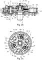
figures 2a ,2b and 2c represent the rotation and oscillatory driving mechanisms of a shaker device of the harvesting unit offigure 1 , respectively in a partially exploded view (figure 2a ), in an assembled axial cross-section view (figure 2b ) and in a radial cross-section top view (figure 2c ); -
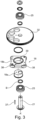
figure 3 represents partially in exploded view the oscillatory driving mechanism offigures 2a ,2b and 2c . - In relation to those figures, we describe below a harvesting unit, as well as a harvesting machine on which such a harvesting unit is mounted.
- The harvesting machine is in particular arranged for the mechanical harvesting of fruits growing on plants, such as trees or bushes, that are arranged in rows, such as grapes, berries, coffee beans, olives, almonds, oranges, citrus, and other fruits.
- More particularly, the harvesting machine is intended for harvesting olives, said machine being in particular intended to a mode for planting olive trees that is said intensive.
- To that end, the harvesting machine comprises a motorized support structure, which can be equipped in particular with a driver station, and that is movable along rows of plants to be harvested, a harvesting unit being mounted on said structure for straddling at least one of said rows of plants and detaching fruits from said plants.
- In particular, the harvesting unit can be mounted on the support structure permanently or removably, so as to be replaceable by other equipment and accessories, for example spraying equipment, pruning equipment or equipment for working the soil.
- The harvesting machine can comprise at least one hydraulic motor connected to wheels or tracks for enabling the movement of the support structure. In particular, the support structure can be a tractor equipped with four driving and/or steering wheels that are each coupled with a hydraulic motor that is provided with a closed loop hydrostatic transmission circuit.
- In particular, the rotation speed of the hydraulic motors can be regulated by a control system with a flow rate proportional to the travel speed of the support structure, said control system possibly being electronical and enabling to correct said rotation speed according to the variations of said travel speed (speed reduction, differences between the travel speed in uphill and downhill slopes, slipping).
- The harvesting machine can also include a recovery unit for recovering the crop detached by the harvesting unit, as well as a unit for cleaning and/or sorting said detached crop to eliminate components other than fruit, in particular leaves, leaf stalks and wood particles, before the storage of said crop in at least one hopper provided for that purpose on the harvesting machine or in an ancillary trailer.
- The harvesting unit comprises a
chassis 1 that can be mounted on the support structure in a fixed or in a pendulum manner about a horizontal and longitudinal axis. In particular, thechassis 1 may comprise severalmetallic profiles 2 that can be assembled by welding. - The harvesting unit comprises a shaker system which comprises at least one shaker device 3 mounted on the
chassis 1. In relation tofigure 1 , thechassis 1 delimits atunnel 4 into which plants to be harvested are introduced successively to move through said tunnel between respective openings at the front and at the rear of said tunnel, the shaker system comprising two shaker devices 3 that are arranged respectively on one side of said tunnel to delimit said tunnel transversely. - Each shaker device 3 comprises a drum 5 that is mounted for rotation on the
chassis 1 and that is operable to detach the crop form the plants introduced into theharvesting tunnel 4. - The drums 5 present a general cylindrical geometry and comprise each a
shaft 6 mounted for rotation on thechassis 1 about a vertical axis A, as well as several shaker organs 7 which extend transversally and are vertically spaced from each other along the rotation axis A, said shaker organs being driven for rotation by theshaft 6. - In particular, the shaker organs 7 extend along substantially the whole height of a drum 5, in order to optimize the shaking height, which enables to harvest in a satisfactory manner the fruits disposed on the whole height of the plants.
- Moreover, each shaker organ 7 can be fixed to the
shaft 6 in a reversible manner, in order to be replaceable by another shaker organ 7 with for example a different form and/or a different size, in accordance with the type of crop to be detached. - As shown in
figure 1 , the shaker organs 7 are vertically stacked on the rotatingshaft 6 of each drum 5. Each shaker organ 7 comprises a ring 8 that is fixed around theshaft 6 and from whichseveral shaker rods 9 extend radially. - Each
shaker rod 9 is arranged to exert a shaking effort on the plants independently from theother shaker rods 9, said rod comprising an inner end that is fixed to the ring 8 and a free end that is opposed to the rotatingshaft 6. - The
shaker rods 9 can present a cross section that is small compared to their length, and can be made of a flexible material, for example, a polyester resin charged with fiberglass, or polyamide, said material having an optimal flexibility/rigidity trade-off for ensuring an efficient shaking of the plants while ensuring the preservation of said plants. It is also possible to provideshaker rods 9 made of a more flexible material, such as for example polyurethane. - Moreover,
shaker rods 9 can be hollow or full, or they can have a structure with a core having the desired flexibility properties and surrounded by a layer made of a wear material that is different from the material of the core. - Each shaker device 3 comprises a rotational driving mechanism of its drum 5, said mechanism comprising a driven
body 10 and adriving device 11 engaged with said driven body to steer its rotation about the vertical axis A. - In particular, the harvesting machine can be equipped with means for controlling the driving device such that the rotation driving speed of the drum 5 is set according to the travel speed of the support structure on the field.
- This control of the rotation driving speed of the drums enables to control optimally and continuously the shaking of the plants, in particular concerning the effort exerted by the
shaker rods 9 on said plants, which enables to harvest the crop efficiently while preserving the integrity of said plants. - The rotational driving mechanisms can be driven by hydraulic means that are integrated either directly into the hydrostatic transmission circuit for the movement of the support structure, or into an auxiliary transmission circuit that is independent and parallel to said movement transmission circuit, said hydraulic driving means being controlled in particular through a flow rate control that is proportional to the movement of the support structure.
- According to a variant, the rotational driving mechanisms and/or the movement of the support structure can be driven by any other known driving means, for example through electrical means.
- As shown in
figure 1 , the harvesting unit comprises a first centralhorizontal rotating shaft 12 that is connected by means of atransmission chain 13 to afirst power input 14, in particular linked to the driving means of the support structure, so as to be driven in rotation according to the power source provided at said first input. - Moreover, the rotational driving mechanisms of each drum 5 comprise a
speed reducer 15 that is connected to thefirst power input 14 through thehorizontal shaft 12, the driving device of said mechanism comprising a vertical rotatingshaft 11 that is connected at the output of said reducer to be driven in rotation by the power provided by said reducer. Finally, each drivenbody 10 comprises atoothed crown 16 that is engaged with agear 17 mounted on the drivenshaft 11, so as to be steered in rotation about the vertical axis A by the rotation of said driven shaft. - The shaker devices 3 also comprise each an oscillatory driving mechanism of their respective drum 5 about the respective vertical axis A thereof. Each oscillatory driving mechanism comprises at least one
eccentric module 18 and a driving device 19 engaged with said module to steer its rotation, said module being connected to theshaft 6 by amechanical member 20 arranged to transform the eccentric rotation of said module into an oscillation of theshaft 6 of the drum 5. - In particular, the oscillatory and rotational movements of the drum 5 are superimposed to one another, which enables to improve the shaking effort on the plants.
- To that effect, the eccentric module(s) 18 is (are) mounted for rotation on the driven
body 10, themechanical member 20 being arranged to transmit the rotation of said driven body to theshaft 6. - Thus, the rotational and oscillatory driving mechanisms are implemented in a particularly simple and compact manner, while presenting an improved resistance to the mechanical constraints transmitted by the
shaker rods 9. - In the embodiment shown, each oscillatory driving mechanism comprises three
eccentric modules 18 that are angularly distributed on the drivenbody 10, which enables a better repartition of the oscillatory efforts around theshaft 6 of the drum 5. - In relation to
figures 2b and 2c , the oscillatory driving mechanism comprises threeplanet shafts 21 that are each mounted for rotation on the drivenbody 10 about respectively a planet vertical axis A', eacheccentric module 18 being mounted on respectively oneplanet shaft 21. - Each driven
body 10 comprises alower plate 10a on which thetoothed crown 16 is associated in rotation, said lower plate comprising acentral bore 22 wherein theshaft 6 is mounted for free rotation about the vertical axis A, in particular by means of aball bearing 23. - Each driven
body 10 also comprises anupper plate 10b that is mounted onto thelower plate 10a, in particular by means ofseveral bolts 24 that also ensures the mounting of thetoothed crown 16, eachplanet shaft 21 comprising upper and lower ends that are mounted for rotation on respectively the upper 10b and lower 10a plates, in particular by means ofroller bearings 25. - Each driven
body 10 comprises threereinforcement blocks 26 that are mounted between the upper 10b and lower 10a plates while being angularly distributed around the vertical axis A, so as to ensure an improved distribution of said reinforcement within the drivenbody 10. Moreover, the drivenbodies 10 comprise each three lubrication means 27 that are mounted on theupper plate 10b adjacent respectively oneplanet shaft 21. - As shown in
figure 1 , the harvesting unit comprises a second central horizontalrotating shaft 28 that is connected through transmission means, for example gearing means, a transmission chain and/or a transmission belt, to asecond power input 29, so as to be driven in rotation according to the power source provided at said second input. - Moreover, the oscillatory driving mechanisms of each drum 5 comprise a
speed reducer 30 that is connected to thesecond input 29 through the secondhorizontal shaft 28, the driving device 19 of said mechanism comprising an upper piece 19a that is mounted for rotation about the vertical axis A at the output of said reducer, so as to be driven in rotation by the power provided by said reducer. - Finally, the driving device 19 comprises a
lower piece 19b associated in rotation with the upper piece 19a, said lower piece comprising atoothed sun gear 31 that is geared with planet gears 32 that are each associated in rotation to respectively aplanet shaft 21, so as to steer the rotation of eacheccentric module 18. - In particular, the
upper plate 10b comprises acentral bore 33 wherein thelower piece 19b with thesun gear 31 is mounted for rotation, for example by means of a ball bearing 34. In the same way, thesun gear 31 is mounted for rotation around theshaft 6 of the drum 5 by means of aball bearing 35. - The
mechanical member 20 compriseswindows 36 wherein respectively one eccentric module is mounted, said mounting being operable to transform the rotation of said eccentric module into an oscillation of theshaft 6. - In the embodiment shown, the
mechanical member 20 comprises acentral bore 20a wherein theshaft 6 is fixedly mounted, and threelobes 20b that are angularly distributed around theshaft 6 and that comprise each such awindow 36. - According to an embodiment not shown, the oscillatory driving mechanism can comprise two eccentric modules of different eccentricity, but having the same external dimensions which are axially spaced from each other along a
planet shaft 21, said planet shaft being mounted in translation along the corresponding planet vertical axis A' for allowing selective mounting of one of said modules inside thewindow 36. - Thus, according to the desired amplitude of oscillation, which depends in particular on the type of plant to be shaken, the operator of the harvesting machine can selectively shift the corresponding eccentric module into the
window 36, for example through command means provided for that purpose into the driver station. Alternatively, the two eccentric modules can be mounted at a fixed vertical position on theplanet shaft 21 and themechanical member 20 can be shifted vertically to make the window orwindows 36 engage the one or other eccentric module. - As shown in
figures 2b and3 , theeccentric modules 18 comprise each acylindrical base 18a that is mounted on thecorresponding planet shaft 21 so that the revolution axis B of said base is offset from the planet vertical axis A', said base being rotatably coupled to anenvelope 18b that is arranged inside thewindow 36. - In particular, the
cylindrical base 18a is axially stacked under theplanet gear 32, so as to improve the compactness of the assembly. Moreover, thecylindrical base 18a is fixed to theplanet gear 32, in particular by means of abolt 37. - The
envelope 18b is mounted for radial translation inside thewindow 36, while being immobilised in the circumferential direction, so as to exert circumferential pushing forces alternatively against the oppositeradial sides 36a of said window upon rotation of theplanet shaft 21, and then to generate alternative oscillations of themechanical member 20 about the vertical axis A. - The
envelope 18b is provided with at least tworollers 38 that are mounted for rotation on respectively one lateral side of said envelope, said rollers being arranged to roll along respectively oneradial side 36a of thewindow 36 upon radial translation of theenvelope 18b inside said window, so as to facilitate said radial translation. - In the embodiment shown, the
envelope 18b has a substantially square shape with rounded corners and comprises fourrollers 38 that are each mounted for rotation on one of said corners. Moreover, theenvelope 18b comprises acentral bore 39 wherein the cylindrical base is fitted. - Although the present invention has been described with reference to a particular embodiment of the harvesting unit, other embodiments can be conceived without departing from the scope of the invention as defined by the accompanying claims. For instance, the eccentric module may comprise a crank connected to the
planet gear 6 and having an eccentric shaft portion provided with a roller that is guided in a radially extending slot in the mechanical member, the slot taking the function of the window in the above embodiment. Such mounting would not require an envelope. It is also conceivable to use two eccentric modules, arranged on opposite sides of thedrum shaft 6, or to use four or more eccentric modules, evenly distributed around this shaft. The driving mechanisms may also be provided at the lower end of thedrum shaft 6, for easier access during repair and servicing operations.
Claims (15)
- Harvesting unit comprising a chassis (1) intended to be moved along rows of plants to be harvested, and a shaker system including at least one shaker device (3), said shaker device comprising:- a drum (5) operable to detach a crop from said plants, said drum comprising a drum shaft (6) mounted for rotation on said chassis about a vertical axis (A) and shaker organs (7) mounted to said drum shaft;- a rotational driving mechanism of said drum (5), said mechanism comprising a driven body (10) and a first driving device (11) engaged with said driven body to steer its rotation about said vertical axis (A);- an oscillatory driving mechanism of said drum (5) about said vertical axis (A), said mechanism comprising at least one eccentric module (18) and a second driving device (19) engaged with said module to steer its rotation, said module being drivingly connected to the drum shaft (6) by a mechanical member (20) operable to transform the eccentric rotation of said module into an oscillation of said drum shaft (6), the eccentric module (18) is mounted for rotation on the driven body (10) of the rotational driving mechanism, the mechanical member (20) being arranged to transmit the rotation of said driven body to the drum shaft (6);said harvesting unit being characterized in that the mechanical member (20) comprises a window (36) wherein the eccentric module (18) is mounted, the mounting of said eccentric module in said window being operable to transform the rotation of said eccentric module (18) into an oscillation of the mechanical member (20).
- Harvesting unit according to claim 1, characterized in that the oscillatory driving mechanism comprises a planet shaft (21) that is mounted for rotation on the driven body (10) about a planet vertical axis (A'), the eccentric module (18) being mounted to said planet shaft.
- Harvesting unit according to claim 1 or 2, characterized in that the eccentric module (18) is mounted for radial translation relative to the mechanical member (20) inside the window (36).
- Harvesting unit according to any one of claims 1 to 3, characterized in that the eccentric module (18) is immobilised in the circumferential direction relative to the mechanical member (20) inside the window (36).
- Harvesting unit according to any of claims 2 to 4, characterized in that the eccentric module (18) comprises a cylindrical base (18a) that is affixed to the planet shaft (21) so that the axis (B) of said cylindrical base is offset from the planet vertical axis (A'), said cylindrical base being rotatably coupled to an envelope (18b) that is arranged inside the window (36).
- Harvesting unit according to claim 5, characterized in that the envelope (18b) comprises at least two rollers (38) that are mounted for rotation on opposite sides of said envelope, said rollers being arranged to roll along respective opposite sides (36a) of the window (36) upon radial translation of the envelope (18b) inside said window.
- Harvesting unit according to any one of claims 2 to 6, characterized in that the oscillatory driving mechanism comprises two eccentric modules (18) of different eccentricity which are axially spaced from each other along the planet shaft (21), said planet shaft being mounted for translation along the planet vertical axis (A') for allowing selective mounting of one of said modules inside the window (36).
- Harvesting unit according to any one of claims 2 to 7, characterized in that the second driving device (19) of the oscillatory driving mechanism comprises a sun gear (31) that is mounted for rotation about the vertical axis (A), said sun gear meshing with a planet gear (32) associated in rotation to the planet shaft (21) to steer the rotation of the eccentric module (18).
- Harvesting unit according to claim 8 when depending from claim 5, characterized in that the cylindrical base (18a) is axially stacked and fixed under the planet gear (32).
- Harvesting unit according to any one of claims 2 to 9, characterized in that the driven body (10) comprises an upper plate (10b) onto which the planet shaft (21) is mounted for rotation.
- Harvesting unit according to any one of claims 1 to 10, characterized in that the oscillatory driving mechanism comprises three eccentric modules (18) that are angularly distributed on the driven body (10).
- Harvesting unit according to claim 11, characterized in that the mechanical member (20) comprises three lobes (20b) that are angularly distributed around the drum shaft (6), each lobe (20b) comprising a window (36) wherein respectively one eccentric module (18) is mounted.
- Harvesting unit according to any one of claims 1 to 12, characterized in that the chassis (1) delimits a tunnel (4) for successive introduction of plants to be harvested, the shaker system comprising two shaker devices (3) that are arranged respectively on one side of said tunnel.
- Harvesting machine comprising a motorised support structure that is movable along rows of plants, a harvesting unit according to any one of claims 1 to 13 being mounted on said motorised support structure for detaching the crop from said plants.
- Harvesting machine according to claim 14, characterized in that it comprises means for controlling the driving device (11) such that the rotation driving speed of the at least one drum (5) is set according to the travelling speed of the support structure.
Applications Claiming Priority (2)
| Application Number | Priority Date | Filing Date | Title |
|---|---|---|---|
| FR1857780 | 2018-08-29 | ||
| PCT/EP2019/072695 WO2020043656A1 (en) | 2018-08-29 | 2019-08-26 | Harvesting unit |
Publications (2)
| Publication Number | Publication Date |
|---|---|
| EP3843527A1 EP3843527A1 (en) | 2021-07-07 |
| EP3843527B1 true EP3843527B1 (en) | 2024-02-28 |
Family
ID=63963220
Family Applications (1)
| Application Number | Title | Priority Date | Filing Date |
|---|---|---|---|
| EP19759351.0A Active EP3843527B1 (en) | 2018-08-29 | 2019-08-26 | Harvesting unit |
Country Status (6)
| Country | Link |
|---|---|
| US (1) | US12279559B2 (en) |
| EP (1) | EP3843527B1 (en) |
| CN (1) | CN112839506B (en) |
| AU (1) | AU2019328256B2 (en) |
| ES (1) | ES2988925T3 (en) |
| WO (1) | WO2020043656A1 (en) |
Families Citing this family (5)
| Publication number | Priority date | Publication date | Assignee | Title |
|---|---|---|---|---|
| CN114271106A (en) * | 2021-11-10 | 2022-04-05 | 铁建重工新疆有限公司 | Inertial vibration fruit-seedling separating device |
| CN114271105A (en) * | 2021-11-10 | 2022-04-05 | 铁建重工新疆有限公司 | Inertial vibration fruit-seedling separating device |
| EP4527184A1 (en) * | 2023-09-21 | 2025-03-26 | CNH Industrial France | Harvesting unit comprising crop collecting mats |
| US20250268141A1 (en) * | 2024-02-26 | 2025-08-28 | Cnh Industrial France S.A.S | Wobble box for a shaker of an agricultural harvester |
| EP4620289A1 (en) * | 2024-03-22 | 2025-09-24 | CNH Industrial France S.A.S. | Harvesting unit with shaker system |
Family Cites Families (31)
| Publication number | Priority date | Publication date | Assignee | Title |
|---|---|---|---|---|
| US3344591A (en) | 1964-04-27 | 1967-10-03 | Oeco Corp | Moving carriage mechanical berry harvester with rotationally oscillative shakers |
| US3507162A (en) | 1967-12-28 | 1970-04-21 | Nissei Kk | Cycloplanetary gearing having a varying output speed ratio |
| GB1435013A (en) * | 1973-05-24 | 1976-05-12 | Lincoln College | Harvesting apparatus |
| US4114463A (en) * | 1975-07-09 | 1978-09-19 | New Zealand Inventions Development Authority | Drive means and harvesting apparatus incorporating same |
| NZ179552A (en) | 1975-12-15 | 1979-11-01 | Peco Ltd | Drive arrangement for vibrating shaker head assemblies of a straddle type berry fruit haryester |
| US4265080A (en) | 1978-03-10 | 1981-05-05 | Goldsmith Sydney A | Harvesting apparatus |
| GB2033197B (en) * | 1978-11-08 | 1982-12-08 | Pattenden Engineering Ltd | Harvesting machine |
| MX150351A (en) | 1979-03-08 | 1984-04-23 | Fmc Corp | IMPROVEMENTS IN MOWER SWEEPING UNIT TO COLLECT USEFUL PLANT SEEDS / LIKE BUSHES |
| FR2558556B1 (en) | 1984-01-23 | 1989-04-07 | Manutention Stockage Cie | MECHANICAL DEVICE FOR TRANSFORMING A CIRCULAR MOTION WITH A CONSTANT SPEED INTO A CIRCULAR MOTION WITH A PERIODICALLY VARIABLE SPEED |
| SU1371598A2 (en) * | 1985-05-23 | 1988-02-07 | Горский Сельскохозяйственный Институт | Shaker for berry picker |
| GB8619504D0 (en) | 1986-08-11 | 1986-09-24 | Rockwell Graphic Systems Ltd | Accelerating drive member |
| US5170614A (en) | 1988-01-29 | 1992-12-15 | Clemson University | Harvesting machinery |
| US4974405A (en) | 1989-10-06 | 1990-12-04 | Littau Eugene G | Harvester with rotationally oscillatable cylindrical shakers |
| US5316519A (en) * | 1992-05-07 | 1994-05-31 | Johnson Farm Machinery Company, Inc. | Multiple weight drum shaker |
| US5685773A (en) | 1995-10-06 | 1997-11-11 | Fmc Corporation | Adjustable four-weight shaker head |
| US5908352A (en) | 1995-10-06 | 1999-06-01 | Fmc Corporation | Adjustable four-weight shaker head |
| AU780423B2 (en) | 1999-10-07 | 2005-03-17 | Ag-Right Enterprises, Inc. | Direct drive vibratory shaker |
| US20050034441A1 (en) | 2003-08-15 | 2005-02-17 | Los Olivares De Venado Tuerto S.A. | Olive harvesting machine |
| DE102004006139A1 (en) | 2004-02-07 | 2005-08-25 | Zf Friedrichshafen Ag | Actuator for e.g. clutch or gear in motor vehicle, has drive motor connected to rotary driven part via planetary gear mechanism |
| US20080060336A1 (en) * | 2006-09-11 | 2008-03-13 | Los Olivares De Venado Tuerto S.A. | Rotovibrating device applicable to knocking down rod headers of harvesting machines |
| CN101482163B (en) | 2008-12-30 | 2013-05-15 | 石河子大学 | Swinging mechanism of corps vine and fruit separation device |
| CN201351725Y (en) * | 2008-12-30 | 2009-11-25 | 石河子大学 | Planet gear rotational mechanism |
| US8887831B2 (en) | 2011-11-17 | 2014-11-18 | Black & Decker Inc. | Transmission for power tool with variable speed ratio |
| AT512571B1 (en) | 2012-01-25 | 2013-12-15 | Fronius Int Gmbh | WIRE SUPPLY DEVICE FOR A WELDING MACHINE RELATING TO A WELDING BURNER |
| DE202012012604U1 (en) | 2012-02-24 | 2013-09-10 | Carl Hoffmann Landmaschinenfachbetrieb Gmbh | Harvesting device and vehicle with such a harvesting device |
| DE202014001781U1 (en) | 2014-03-01 | 2014-04-02 | Carl Hoffmann Landmaschinenfachbetrieb Gmbh | Thinning device and vehicle with such a thinning device |
| FR3045272B1 (en) * | 2015-12-22 | 2018-08-10 | Cnh Industrial France | FRUIT HARVESTING MACHINE |
| CN105850374A (en) * | 2016-04-15 | 2016-08-17 | 浙江大学 | Eccentric rolling vibration mechanism for picking wolfberry fruit |
| CN106233924B (en) | 2016-07-26 | 2019-05-24 | 石河子大学 | A tomato seedling separation vibration generator |
| CN107228164B (en) | 2017-07-13 | 2023-04-14 | 中冶赛迪技术研究中心有限公司 | Small tooth difference planetary gear transmission device with periodically changed transmission ratio |
| CN207099723U (en) * | 2017-07-13 | 2018-03-16 | 浙江理工大学 | A kind of novel clamping vibrating picker for woods fruit |
-
2019
- 2019-08-26 WO PCT/EP2019/072695 patent/WO2020043656A1/en not_active Ceased
- 2019-08-26 EP EP19759351.0A patent/EP3843527B1/en active Active
- 2019-08-26 ES ES19759351T patent/ES2988925T3/en active Active
- 2019-08-26 US US17/272,647 patent/US12279559B2/en active Active
- 2019-08-26 AU AU2019328256A patent/AU2019328256B2/en active Active
- 2019-08-26 CN CN201980064633.XA patent/CN112839506B/en active Active
Also Published As
| Publication number | Publication date |
|---|---|
| US12279559B2 (en) | 2025-04-22 |
| EP3843527A1 (en) | 2021-07-07 |
| ES2988925T3 (en) | 2024-11-22 |
| WO2020043656A1 (en) | 2020-03-05 |
| CN112839506A (en) | 2021-05-25 |
| US20210337732A1 (en) | 2021-11-04 |
| BR112020005916A2 (en) | 2021-03-09 |
| CN112839506B (en) | 2023-04-28 |
| AU2019328256A1 (en) | 2021-03-25 |
| AU2019328256B2 (en) | 2022-10-13 |
Similar Documents
| Publication | Publication Date | Title |
|---|---|---|
| AU2019328256B2 (en) | Harvesting unit | |
| US3344591A (en) | Moving carriage mechanical berry harvester with rotationally oscillative shakers | |
| US4114463A (en) | Drive means and harvesting apparatus incorporating same | |
| US4173859A (en) | Harvesting apparatus | |
| FR3045272A1 (en) | FRUIT HARVESTING MACHINE | |
| GB2033197A (en) | Harvesting machine | |
| EP0857015B1 (en) | Adjustable four-weight shaker head | |
| US3203159A (en) | Method of harvesting berries and similar produce from their plants | |
| EP2677853B1 (en) | Fruit harvesting unit and harvesting machine comprising such unit | |
| EP4620289A1 (en) | Harvesting unit with shaker system | |
| AU2006228421A1 (en) | Shaking machine for harvesting fruit from rows | |
| CN117158191A (en) | Automatic oil tea fruit collecting machine | |
| BR112020005916B1 (en) | HARVESTING UNIT AND HARVESTING MACHINE | |
| US20080060336A1 (en) | Rotovibrating device applicable to knocking down rod headers of harvesting machines | |
| EP1955583A1 (en) | Distributing trailer | |
| US20250268141A1 (en) | Wobble box for a shaker of an agricultural harvester | |
| EP4527184A1 (en) | Harvesting unit comprising crop collecting mats | |
| RU2160985C1 (en) | Fruit harvester shaker | |
| CN2405415Y (en) | Double-driven automatic wheat-cutting machine | |
| CN201248260Y (en) | Peanut harvester | |
| CN1520705A (en) | Self-propelled peanut combine | |
| CN2676599Y (en) | Corn, sunflower straw harvester combined with tractor | |
| RU2021661C1 (en) | Rotor root crop harvester | |
| CN122056180A (en) | Blueberry harvester with vibration reduction structure and amplitude adjustable | |
| CN201467688U (en) | peanut harvester |
Legal Events
| Date | Code | Title | Description |
|---|---|---|---|
| STAA | Information on the status of an ep patent application or granted ep patent |
Free format text: STATUS: UNKNOWN |
|
| STAA | Information on the status of an ep patent application or granted ep patent |
Free format text: STATUS: THE INTERNATIONAL PUBLICATION HAS BEEN MADE |
|
| STAA | Information on the status of an ep patent application or granted ep patent |
Free format text: STATUS: REQUEST FOR EXAMINATION WAS MADE |
|
| PUAI | Public reference made under article 153(3) epc to a published international application that has entered the european phase |
Free format text: ORIGINAL CODE: 0009012 |
|
| 17P | Request for examination filed |
Effective date: 20210329 |
|
| AK | Designated contracting states |
Kind code of ref document: A1 Designated state(s): AL AT BE BG CH CY CZ DE DK EE ES FI FR GB GR HR HU IE IS IT LI LT LU LV MC MK MT NL NO PL PT RO RS SE SI SK SM TR |
|
| DAV | Request for validation of the european patent (deleted) | ||
| DAX | Request for extension of the european patent (deleted) | ||
| GRAP | Despatch of communication of intention to grant a patent |
Free format text: ORIGINAL CODE: EPIDOSNIGR1 |
|
| STAA | Information on the status of an ep patent application or granted ep patent |
Free format text: STATUS: GRANT OF PATENT IS INTENDED |
|
| INTG | Intention to grant announced |
Effective date: 20230928 |
|
| GRAS | Grant fee paid |
Free format text: ORIGINAL CODE: EPIDOSNIGR3 |
|
| GRAA | (expected) grant |
Free format text: ORIGINAL CODE: 0009210 |
|
| STAA | Information on the status of an ep patent application or granted ep patent |
Free format text: STATUS: THE PATENT HAS BEEN GRANTED |
|
| AK | Designated contracting states |
Kind code of ref document: B1 Designated state(s): AL AT BE BG CH CY CZ DE DK EE ES FI FR GB GR HR HU IE IS IT LI LT LU LV MC MK MT NL NO PL PT RO RS SE SI SK SM TR |
|
| REG | Reference to a national code |
Ref country code: GB Ref legal event code: FG4D |
|
| REG | Reference to a national code |
Ref country code: CH Ref legal event code: EP |
|
| REG | Reference to a national code |
Ref country code: DE Ref legal event code: R096 Ref document number: 602019047354 Country of ref document: DE |
|
| REG | Reference to a national code |
Ref country code: IE Ref legal event code: FG4D |
|
| REG | Reference to a national code |
Ref country code: LT Ref legal event code: MG9D |
|
| PG25 | Lapsed in a contracting state [announced via postgrant information from national office to epo] |
Ref country code: IS Free format text: LAPSE BECAUSE OF FAILURE TO SUBMIT A TRANSLATION OF THE DESCRIPTION OR TO PAY THE FEE WITHIN THE PRESCRIBED TIME-LIMIT Effective date: 20240628 |
|
| REG | Reference to a national code |
Ref country code: NL Ref legal event code: MP Effective date: 20240228 |
|
| PG25 | Lapsed in a contracting state [announced via postgrant information from national office to epo] |
Ref country code: LT Free format text: LAPSE BECAUSE OF FAILURE TO SUBMIT A TRANSLATION OF THE DESCRIPTION OR TO PAY THE FEE WITHIN THE PRESCRIBED TIME-LIMIT Effective date: 20240228 |
|
| PG25 | Lapsed in a contracting state [announced via postgrant information from national office to epo] |
Ref country code: GR Free format text: LAPSE BECAUSE OF FAILURE TO SUBMIT A TRANSLATION OF THE DESCRIPTION OR TO PAY THE FEE WITHIN THE PRESCRIBED TIME-LIMIT Effective date: 20240529 |
|
| PG25 | Lapsed in a contracting state [announced via postgrant information from national office to epo] |
Ref country code: RS Free format text: LAPSE BECAUSE OF FAILURE TO SUBMIT A TRANSLATION OF THE DESCRIPTION OR TO PAY THE FEE WITHIN THE PRESCRIBED TIME-LIMIT Effective date: 20240528 Ref country code: HR Free format text: LAPSE BECAUSE OF FAILURE TO SUBMIT A TRANSLATION OF THE DESCRIPTION OR TO PAY THE FEE WITHIN THE PRESCRIBED TIME-LIMIT Effective date: 20240228 Ref country code: NL Free format text: LAPSE BECAUSE OF FAILURE TO SUBMIT A TRANSLATION OF THE DESCRIPTION OR TO PAY THE FEE WITHIN THE PRESCRIBED TIME-LIMIT Effective date: 20240228 |
|
| PG25 | Lapsed in a contracting state [announced via postgrant information from national office to epo] |
Ref country code: RS Free format text: LAPSE BECAUSE OF FAILURE TO SUBMIT A TRANSLATION OF THE DESCRIPTION OR TO PAY THE FEE WITHIN THE PRESCRIBED TIME-LIMIT Effective date: 20240528 Ref country code: NO Free format text: LAPSE BECAUSE OF FAILURE TO SUBMIT A TRANSLATION OF THE DESCRIPTION OR TO PAY THE FEE WITHIN THE PRESCRIBED TIME-LIMIT Effective date: 20240528 Ref country code: NL Free format text: LAPSE BECAUSE OF FAILURE TO SUBMIT A TRANSLATION OF THE DESCRIPTION OR TO PAY THE FEE WITHIN THE PRESCRIBED TIME-LIMIT Effective date: 20240228 Ref country code: LT Free format text: LAPSE BECAUSE OF FAILURE TO SUBMIT A TRANSLATION OF THE DESCRIPTION OR TO PAY THE FEE WITHIN THE PRESCRIBED TIME-LIMIT Effective date: 20240228 Ref country code: IS Free format text: LAPSE BECAUSE OF FAILURE TO SUBMIT A TRANSLATION OF THE DESCRIPTION OR TO PAY THE FEE WITHIN THE PRESCRIBED TIME-LIMIT Effective date: 20240628 Ref country code: HR Free format text: LAPSE BECAUSE OF FAILURE TO SUBMIT A TRANSLATION OF THE DESCRIPTION OR TO PAY THE FEE WITHIN THE PRESCRIBED TIME-LIMIT Effective date: 20240228 Ref country code: GR Free format text: LAPSE BECAUSE OF FAILURE TO SUBMIT A TRANSLATION OF THE DESCRIPTION OR TO PAY THE FEE WITHIN THE PRESCRIBED TIME-LIMIT Effective date: 20240529 Ref country code: FI Free format text: LAPSE BECAUSE OF FAILURE TO SUBMIT A TRANSLATION OF THE DESCRIPTION OR TO PAY THE FEE WITHIN THE PRESCRIBED TIME-LIMIT Effective date: 20240228 Ref country code: BG Free format text: LAPSE BECAUSE OF FAILURE TO SUBMIT A TRANSLATION OF THE DESCRIPTION OR TO PAY THE FEE WITHIN THE PRESCRIBED TIME-LIMIT Effective date: 20240228 |
|
| PG25 | Lapsed in a contracting state [announced via postgrant information from national office to epo] |
Ref country code: PT Free format text: LAPSE BECAUSE OF FAILURE TO SUBMIT A TRANSLATION OF THE DESCRIPTION OR TO PAY THE FEE WITHIN THE PRESCRIBED TIME-LIMIT Effective date: 20240628 Ref country code: PL Free format text: LAPSE BECAUSE OF FAILURE TO SUBMIT A TRANSLATION OF THE DESCRIPTION OR TO PAY THE FEE WITHIN THE PRESCRIBED TIME-LIMIT Effective date: 20240228 |
|
| REG | Reference to a national code |
Ref country code: AT Ref legal event code: MK05 Ref document number: 1660280 Country of ref document: AT Kind code of ref document: T Effective date: 20240228 |
|
| PG25 | Lapsed in a contracting state [announced via postgrant information from national office to epo] |
Ref country code: SE Free format text: LAPSE BECAUSE OF FAILURE TO SUBMIT A TRANSLATION OF THE DESCRIPTION OR TO PAY THE FEE WITHIN THE PRESCRIBED TIME-LIMIT Effective date: 20240228 Ref country code: PT Free format text: LAPSE BECAUSE OF FAILURE TO SUBMIT A TRANSLATION OF THE DESCRIPTION OR TO PAY THE FEE WITHIN THE PRESCRIBED TIME-LIMIT Effective date: 20240628 Ref country code: PL Free format text: LAPSE BECAUSE OF FAILURE TO SUBMIT A TRANSLATION OF THE DESCRIPTION OR TO PAY THE FEE WITHIN THE PRESCRIBED TIME-LIMIT Effective date: 20240228 Ref country code: LV Free format text: LAPSE BECAUSE OF FAILURE TO SUBMIT A TRANSLATION OF THE DESCRIPTION OR TO PAY THE FEE WITHIN THE PRESCRIBED TIME-LIMIT Effective date: 20240228 |
|
| PG25 | Lapsed in a contracting state [announced via postgrant information from national office to epo] |
Ref country code: DK Free format text: LAPSE BECAUSE OF FAILURE TO SUBMIT A TRANSLATION OF THE DESCRIPTION OR TO PAY THE FEE WITHIN THE PRESCRIBED TIME-LIMIT Effective date: 20240228 |
|
| PG25 | Lapsed in a contracting state [announced via postgrant information from national office to epo] |
Ref country code: SM Free format text: LAPSE BECAUSE OF FAILURE TO SUBMIT A TRANSLATION OF THE DESCRIPTION OR TO PAY THE FEE WITHIN THE PRESCRIBED TIME-LIMIT Effective date: 20240228 |
|
| PG25 | Lapsed in a contracting state [announced via postgrant information from national office to epo] |
Ref country code: EE Free format text: LAPSE BECAUSE OF FAILURE TO SUBMIT A TRANSLATION OF THE DESCRIPTION OR TO PAY THE FEE WITHIN THE PRESCRIBED TIME-LIMIT Effective date: 20240228 Ref country code: CZ Free format text: LAPSE BECAUSE OF FAILURE TO SUBMIT A TRANSLATION OF THE DESCRIPTION OR TO PAY THE FEE WITHIN THE PRESCRIBED TIME-LIMIT Effective date: 20240228 |
|
| PG25 | Lapsed in a contracting state [announced via postgrant information from national office to epo] |
Ref country code: AT Free format text: LAPSE BECAUSE OF FAILURE TO SUBMIT A TRANSLATION OF THE DESCRIPTION OR TO PAY THE FEE WITHIN THE PRESCRIBED TIME-LIMIT Effective date: 20240228 |
|
| PG25 | Lapsed in a contracting state [announced via postgrant information from national office to epo] |
Ref country code: SK Free format text: LAPSE BECAUSE OF FAILURE TO SUBMIT A TRANSLATION OF THE DESCRIPTION OR TO PAY THE FEE WITHIN THE PRESCRIBED TIME-LIMIT Effective date: 20240228 |
|
| PG25 | Lapsed in a contracting state [announced via postgrant information from national office to epo] |
Ref country code: SM Free format text: LAPSE BECAUSE OF FAILURE TO SUBMIT A TRANSLATION OF THE DESCRIPTION OR TO PAY THE FEE WITHIN THE PRESCRIBED TIME-LIMIT Effective date: 20240228 Ref country code: SK Free format text: LAPSE BECAUSE OF FAILURE TO SUBMIT A TRANSLATION OF THE DESCRIPTION OR TO PAY THE FEE WITHIN THE PRESCRIBED TIME-LIMIT Effective date: 20240228 Ref country code: RO Free format text: LAPSE BECAUSE OF FAILURE TO SUBMIT A TRANSLATION OF THE DESCRIPTION OR TO PAY THE FEE WITHIN THE PRESCRIBED TIME-LIMIT Effective date: 20240228 Ref country code: EE Free format text: LAPSE BECAUSE OF FAILURE TO SUBMIT A TRANSLATION OF THE DESCRIPTION OR TO PAY THE FEE WITHIN THE PRESCRIBED TIME-LIMIT Effective date: 20240228 Ref country code: DK Free format text: LAPSE BECAUSE OF FAILURE TO SUBMIT A TRANSLATION OF THE DESCRIPTION OR TO PAY THE FEE WITHIN THE PRESCRIBED TIME-LIMIT Effective date: 20240228 Ref country code: CZ Free format text: LAPSE BECAUSE OF FAILURE TO SUBMIT A TRANSLATION OF THE DESCRIPTION OR TO PAY THE FEE WITHIN THE PRESCRIBED TIME-LIMIT Effective date: 20240228 Ref country code: AT Free format text: LAPSE BECAUSE OF FAILURE TO SUBMIT A TRANSLATION OF THE DESCRIPTION OR TO PAY THE FEE WITHIN THE PRESCRIBED TIME-LIMIT Effective date: 20240228 |
|
| REG | Reference to a national code |
Ref country code: ES Ref legal event code: FG2A Ref document number: 2988925 Country of ref document: ES Kind code of ref document: T3 Effective date: 20241122 |
|
| REG | Reference to a national code |
Ref country code: DE Ref legal event code: R097 Ref document number: 602019047354 Country of ref document: DE |
|
| PLBE | No opposition filed within time limit |
Free format text: ORIGINAL CODE: 0009261 |
|
| STAA | Information on the status of an ep patent application or granted ep patent |
Free format text: STATUS: NO OPPOSITION FILED WITHIN TIME LIMIT |
|
| 26N | No opposition filed |
Effective date: 20241129 |
|
| REG | Reference to a national code |
Ref country code: CH Ref legal event code: PL |
|
| PG25 | Lapsed in a contracting state [announced via postgrant information from national office to epo] |
Ref country code: LU Free format text: LAPSE BECAUSE OF NON-PAYMENT OF DUE FEES Effective date: 20240826 |
|
| GBPC | Gb: european patent ceased through non-payment of renewal fee |
Effective date: 20240826 |
|
| PG25 | Lapsed in a contracting state [announced via postgrant information from national office to epo] |
Ref country code: MC Free format text: LAPSE BECAUSE OF FAILURE TO SUBMIT A TRANSLATION OF THE DESCRIPTION OR TO PAY THE FEE WITHIN THE PRESCRIBED TIME-LIMIT Effective date: 20240228 Ref country code: CH Free format text: LAPSE BECAUSE OF NON-PAYMENT OF DUE FEES Effective date: 20240831 Ref country code: SI Free format text: LAPSE BECAUSE OF FAILURE TO SUBMIT A TRANSLATION OF THE DESCRIPTION OR TO PAY THE FEE WITHIN THE PRESCRIBED TIME-LIMIT Effective date: 20240228 |
|
| REG | Reference to a national code |
Ref country code: BE Ref legal event code: MM Effective date: 20240831 |
|
| PG25 | Lapsed in a contracting state [announced via postgrant information from national office to epo] |
Ref country code: GB Free format text: LAPSE BECAUSE OF NON-PAYMENT OF DUE FEES Effective date: 20240826 |
|
| PG25 | Lapsed in a contracting state [announced via postgrant information from national office to epo] |
Ref country code: BE Free format text: LAPSE BECAUSE OF NON-PAYMENT OF DUE FEES Effective date: 20240831 |
|
| PG25 | Lapsed in a contracting state [announced via postgrant information from national office to epo] |
Ref country code: IE Free format text: LAPSE BECAUSE OF NON-PAYMENT OF DUE FEES Effective date: 20240826 |
|
| PGFP | Annual fee paid to national office [announced via postgrant information from national office to epo] |
Ref country code: ES Payment date: 20250916 Year of fee payment: 7 |
|
| PGFP | Annual fee paid to national office [announced via postgrant information from national office to epo] |
Ref country code: DE Payment date: 20250827 Year of fee payment: 7 |
|
| PGFP | Annual fee paid to national office [announced via postgrant information from national office to epo] |
Ref country code: IT Payment date: 20250825 Year of fee payment: 7 |
|
| PGFP | Annual fee paid to national office [announced via postgrant information from national office to epo] |
Ref country code: FR Payment date: 20250825 Year of fee payment: 7 |
|
| PG25 | Lapsed in a contracting state [announced via postgrant information from national office to epo] |
Ref country code: CY Free format text: LAPSE BECAUSE OF FAILURE TO SUBMIT A TRANSLATION OF THE DESCRIPTION OR TO PAY THE FEE WITHIN THE PRESCRIBED TIME-LIMIT; INVALID AB INITIO Effective date: 20190826 |
|
| PG25 | Lapsed in a contracting state [announced via postgrant information from national office to epo] |
Ref country code: HU Free format text: LAPSE BECAUSE OF FAILURE TO SUBMIT A TRANSLATION OF THE DESCRIPTION OR TO PAY THE FEE WITHIN THE PRESCRIBED TIME-LIMIT; INVALID AB INITIO Effective date: 20190826 |