EP3843466A2 - Leistungssteuerungsverfahren und -vorrichtung - Google Patents
Leistungssteuerungsverfahren und -vorrichtung Download PDFInfo
- Publication number
- EP3843466A2 EP3843466A2 EP20200054.3A EP20200054A EP3843466A2 EP 3843466 A2 EP3843466 A2 EP 3843466A2 EP 20200054 A EP20200054 A EP 20200054A EP 3843466 A2 EP3843466 A2 EP 3843466A2
- Authority
- EP
- European Patent Office
- Prior art keywords
- srs
- power control
- carrier
- power
- control parameter
- Prior art date
- Legal status (The legal status is an assumption and is not a legal conclusion. Google has not performed a legal analysis and makes no representation as to the accuracy of the status listed.)
- Granted
Links
Images

Classifications
-
- H—ELECTRICITY
- H04—ELECTRIC COMMUNICATION TECHNIQUE
- H04L—TRANSMISSION OF DIGITAL INFORMATION, e.g. TELEGRAPHIC COMMUNICATION
- H04L5/00—Arrangements affording multiple use of the transmission path
- H04L5/003—Arrangements for allocating sub-channels of the transmission path
- H04L5/0048—Allocation of pilot signals, i.e. of signals known to the receiver
- H04L5/0051—Allocation of pilot signals, i.e. of signals known to the receiver of dedicated pilots, i.e. pilots destined for a single user or terminal
-
- H—ELECTRICITY
- H04—ELECTRIC COMMUNICATION TECHNIQUE
- H04W—WIRELESS COMMUNICATION NETWORKS
- H04W52/00—Power management, e.g. Transmission Power Control [TPC] or power classes
- H04W52/04—Transmission power control [TPC]
- H04W52/06—TPC algorithms
- H04W52/08—Closed loop power control
-
- H—ELECTRICITY
- H04—ELECTRIC COMMUNICATION TECHNIQUE
- H04W—WIRELESS COMMUNICATION NETWORKS
- H04W52/00—Power management, e.g. Transmission Power Control [TPC] or power classes
- H04W52/04—Transmission power control [TPC]
- H04W52/06—TPC algorithms
- H04W52/10—Open loop power control
-
- H—ELECTRICITY
- H04—ELECTRIC COMMUNICATION TECHNIQUE
- H04W—WIRELESS COMMUNICATION NETWORKS
- H04W52/00—Power management, e.g. Transmission Power Control [TPC] or power classes
- H04W52/04—Transmission power control [TPC]
- H04W52/06—TPC algorithms
- H04W52/14—Separate analysis of uplink or downlink
- H04W52/143—Downlink power control
-
- H—ELECTRICITY
- H04—ELECTRIC COMMUNICATION TECHNIQUE
- H04W—WIRELESS COMMUNICATION NETWORKS
- H04W52/00—Power management, e.g. Transmission Power Control [TPC] or power classes
- H04W52/04—Transmission power control [TPC]
- H04W52/06—TPC algorithms
- H04W52/14—Separate analysis of uplink or downlink
- H04W52/146—Uplink power control
-
- H—ELECTRICITY
- H04—ELECTRIC COMMUNICATION TECHNIQUE
- H04W—WIRELESS COMMUNICATION NETWORKS
- H04W52/00—Power management, e.g. Transmission Power Control [TPC] or power classes
- H04W52/04—Transmission power control [TPC]
- H04W52/18—TPC being performed according to specific parameters
-
- H—ELECTRICITY
- H04—ELECTRIC COMMUNICATION TECHNIQUE
- H04W—WIRELESS COMMUNICATION NETWORKS
- H04W52/00—Power management, e.g. Transmission Power Control [TPC] or power classes
- H04W52/04—Transmission power control [TPC]
- H04W52/18—TPC being performed according to specific parameters
- H04W52/24—TPC being performed according to specific parameters using SIR [Signal to Interference Ratio] or other wireless path parameters
- H04W52/242—TPC being performed according to specific parameters using SIR [Signal to Interference Ratio] or other wireless path parameters taking into account path loss
-
- H—ELECTRICITY
- H04—ELECTRIC COMMUNICATION TECHNIQUE
- H04W—WIRELESS COMMUNICATION NETWORKS
- H04W52/00—Power management, e.g. Transmission Power Control [TPC] or power classes
- H04W52/04—Transmission power control [TPC]
- H04W52/30—Transmission power control [TPC] using constraints in the total amount of available transmission power
- H04W52/32—TPC of broadcast or control channels
- H04W52/325—Power control of control or pilot channels
-
- H—ELECTRICITY
- H04—ELECTRIC COMMUNICATION TECHNIQUE
- H04W—WIRELESS COMMUNICATION NETWORKS
- H04W72/00—Local resource management
- H04W72/20—Control channels or signalling for resource management
- H04W72/23—Control channels or signalling for resource management in the downlink direction of a wireless link, i.e. towards a terminal
-
- H—ELECTRICITY
- H04—ELECTRIC COMMUNICATION TECHNIQUE
- H04L—TRANSMISSION OF DIGITAL INFORMATION, e.g. TELEGRAPHIC COMMUNICATION
- H04L5/00—Arrangements affording multiple use of the transmission path
- H04L5/0001—Arrangements for dividing the transmission path
- H04L5/0003—Two-dimensional division
- H04L5/0005—Time-frequency
- H04L5/0007—Time-frequency the frequencies being orthogonal, e.g. OFDM(A) or DMT
- H04L5/001—Time-frequency the frequencies being orthogonal, e.g. OFDM(A) or DMT the frequencies being arranged in component carriers
-
- H—ELECTRICITY
- H04—ELECTRIC COMMUNICATION TECHNIQUE
- H04L—TRANSMISSION OF DIGITAL INFORMATION, e.g. TELEGRAPHIC COMMUNICATION
- H04L5/00—Arrangements affording multiple use of the transmission path
- H04L5/0091—Signalling for the administration of the divided path, e.g. signalling of configuration information
- H04L5/0096—Indication of changes in allocation
- H04L5/0098—Signalling of the activation or deactivation of component carriers, subcarriers or frequency bands
-
- H—ELECTRICITY
- H04—ELECTRIC COMMUNICATION TECHNIQUE
- H04W—WIRELESS COMMUNICATION NETWORKS
- H04W52/00—Power management, e.g. Transmission Power Control [TPC] or power classes
- H04W52/04—Transmission power control [TPC]
- H04W52/30—Transmission power control [TPC] using constraints in the total amount of available transmission power
- H04W52/34—TPC management, i.e. sharing limited amount of power among users or channels or data types, e.g. cell loading
-
- H—ELECTRICITY
- H04—ELECTRIC COMMUNICATION TECHNIQUE
- H04W—WIRELESS COMMUNICATION NETWORKS
- H04W8/00—Network data management
- H04W8/26—Network addressing or numbering for mobility support
Definitions
- Embodiments of the present invention relate to communications technologies, and in particular, to a power control method and apparatus.
- LTE-A Long Term Evolution Advanced
- UE User Equipment
- UE User Equipment
- channel non-reciprocity for measurement of some downlink channels, measurement of the downlink channel is obtained by using a channel non-reciprocity feature, for example, a precoding matrix index (precoding matrix index, PMI for short) and an uplink sounding reference signal (Sounding Reference Symbol, SRS for short).
- a channel non-reciprocity feature for example, a precoding matrix index (precoding matrix index, PMI for short) and an uplink sounding reference signal (Sounding Reference Symbol, SRS for short).
- carrier switching is required. For example, in a first subframe, a carrier 1 and a carrier 2 are used for downlink transmission. When SRS transmission is required in a second subframe, carrier switching is performed. The carrier 2 is changed to a carrier 3 and the carrier 3 is used to transmit the SRS. In addition, transmit power for the SRS needs to be controlled to ensure that the SRS is received correctly.
- Parameter setting of a prior-art SRS power control solution depends on some parameters related to physical uplink shared channel (Physical Uplink Shared Channel, PUSCH for short) power control, while the UE cannot obtain the parameters related to PUSCH power control on the switched-to carrier used for SRS transmission. As a result, SRS power control is not possible, and the SRS cannot be received correctly.
- physical Uplink shared channel Physical Uplink Shared Channel, PUSCH for short
- Embodiments of the present invention provide a power control method and apparatus, so that an SRS is transmitted at optimal transmit power on a switched-to carrier, ensuring that the SRS is received correctly.
- an embodiment of the present invention provides a power control method, including: obtaining a power control parameter for a sounding reference signal SRS, where the power control parameter for the SRS includes at least one of a target power parameter value for the SRS, a path loss compensation factor, and a closed-loop power control parameter value for the SRS; and determining transmit power for the SRS on a first carrier based on the power control parameter for the SRS.
- UE can calculate the transmit power for the SRS on the first carrier based on a newly configured power control parameter for the SRS, so that the SRS is transmitted at optimal transmit power on a switched-to carrier, ensuring that the SRS is received correctly.
- the first carrier is a carrier on which no physical uplink shared channel PUSCH is sent.
- the obtaining a power control parameter for a sounding reference signal SRS includes: receiving power control signaling or cross-carrier power control signaling sent by a base station.
- the power control signaling includes open-loop power control signaling and/or closed-loop power control signaling.
- the obtaining a power control parameter for a sounding reference signal SRS includes: obtaining the power control parameter for the SRS from the power control signaling or the cross-carrier power control signaling.
- the power control signaling or the cross-carrier power control signaling includes radio resource control RRC signaling or physical layer signaling.
- the UE can obtain the power control parameter for the SRS in different manners.
- the manner of obtaining the power control parameter for the SRS is flexible and features ease of operation.
- the target power parameter value for the SRS is a parameter value obtained based on a preamble initial received target power value; or the target power parameter value for the SRS is a parameter value obtained based on the preamble initial received target power value and a power adjustment value.
- the obtaining the power control parameter from the power control signaling or the cross-carrier power control signaling includes: parsing out the power control parameter for the SRS from the power control signaling or the cross-carrier power control signaling based on a first radio network temporary identifier RNTI.
- the determining transmit power for the SRS based on the power control parameter for the SRS includes: obtaining the transmit power for the SRS based on at least one of maximum transmit power of user equipment UE, a transmit power adjustment value for the SRS, transmission bandwidth for the SRS, the target power parameter value for the SRS, the path loss compensation factor, and an estimated downlink path loss value.
- the UE can calculate the transmit power for the SRS accurately, so as to ensure SRS transmission quality.
- the method before the determining transmit power for the SRS based on the power control parameter for the SRS, the method further includes: determining whether the SRS is configured periodically or configured aperiodically.
- the closed-loop power control parameter value for the SRS is an absolute value or a relative adjustment value.
- the method before the obtaining the power control parameter for the SRS, the method further includes: obtaining transmission power control TPC information, where the TPC information is information scrambled with the first radio network temporary identifier RNTI.
- the obtaining the power control parameter for the SRS includes: parsing out the closed-loop power control parameter value for the SRS from the TPC information based on the first RNTI.
- the method further includes: obtaining downlink control information DCI.
- the obtaining the power control parameter for the SRS includes: obtaining the closed-loop power control parameter value for the SRS based on the DCI.
- the DCI if the DCI is control information obtained on a second carrier, the DCI includes at least a first carrier index.
- the second carrier is a switching-from carrier or any carrier other than a switched-to carrier
- the first carrier is the switched-to carrier
- the obtaining the closed-loop power control parameter value for the SRS based on the DCI includes: obtaining the closed-loop power control parameter value for the SRS on a carrier corresponding to the first carrier index.
- the obtaining the closed-loop power control parameter value for the SRS based on the DCI includes: obtaining the closed-loop power control parameter value for the SRS from the DCI.
- the UE can obtain the closed-loop power control parameter value for the SRS in different manners.
- a new DCI format is defined, so that the UE can obtain a complete power control parameter for the SRS, to ensure SRS transmission reliability.
- the method further includes: determining the closed-loop power control parameter value for the SRS based on at least one of closed-loop power control information or a relative adjustment value for an SRS in a previous subframe.
- the determining transmit power for the SRS based on the power control parameter for the SRS includes: obtaining the transmit power for the SRS based on at least one of maximum transmit power of the user equipment UE, a transmit power adjustment value for the SRS, transmission bandwidth for the SRS, the target power parameter value for the SRS, the path loss compensation factor, an estimated downlink path loss value, and the closed-loop power control parameter for the SRS.
- the UE can calculate the transmit power for the SRS in a closed-loop circumstance accurately, so as to ensure that the SRS can be received correctly in different circumstances.
- an embodiment of the present invention provides a power control method, including: obtaining transmit power in a symbol overlapping portion of a first subframe and a second subframe, where the first subframe is a subframe in which a sounding reference signal SRS is transmitted on a first carrier, and the second subframe is a subframe in which an SRS or a physical channel is transmitted on a second carrier; and if the transmit power is greater than maximum transmit power of user equipment UE, controlling transmit power for a to-be-transmitted signal, where the to-be-transmitted signal includes the SRS and/or the physical channel.
- the method before the controlling transmit power for a to-be-transmitted signal, the method further includes: determining whether the SRS is configured periodically or configured aperiodically.
- the controlling transmit power for a to-be-transmitted signal includes: controlling the transmit power for the to-be-transmitted signal based on a periodical configuration of the SRS; or controlling the transmit power for the to-be-transmitted signal based on an aperiodical configuration of the SRS.
- the controlling transmit power for a to-be-transmitted signal includes: dropping the SRS or performing power scaling for the SRS.
- the controlling transmit power for a to-be-transmitted signal includes: dropping the PUSCH or performing power scaling for the PUSCH.
- the controlling transmit power for a to-be-transmitted signal includes: dropping the SRS or performing power scaling for the SRS.
- the controlling transmit power for a to-be-transmitted signal includes: dropping the SRS or performing power scaling for the SRS; or dropping the PUCCH or performing power scaling for the PUCCH.
- the controlling transmit power for a to-be-transmitted signal includes: dropping the SRS or performing power scaling for the SRS.
- an embodiment of the present invention provides a power control method, where the method includes: obtaining a power control parameter for a sounding reference signal SRS on a first carrier, where the power control parameter for the SRS includes at least one of a target power parameter value for the SRS, a path loss compensation factor, and a closed-loop power control parameter value for the SRS; and sending the power control parameter for the SRS to user equipment UE, so that the UE determines transmit power for the SRS on the first carrier based on the power control parameter for the SRS.
- the first carrier is a carrier on which no physical uplink shared channel PUSCH is sent.
- the sending the power control parameter for the SRS to user equipment UE includes: sending the power control parameter for the SRS to the UE by using power control signaling or cross-carrier power control signaling.
- the power control signaling includes open-loop power control signaling and/or closed-loop power control signaling.
- the power control signaling or the cross-carrier power control signaling includes radio resource control RRC signaling or physical layer signaling.
- the target power parameter value for the SRS is a parameter value obtained based on a preamble initial received target power value; or the target power parameter value for the SRS is a parameter value obtained based on the preamble initial received target power value and a power adjustment value.
- the sending the power control parameter for the SRS to the UE by using power control signaling or cross-carrier power control signaling includes: scrambling the power control parameter for the SRS based on a first radio network temporary identifier RNTI, to generate the power control signaling or the cross-carrier power control signaling; and sending the power control signaling or the cross-carrier power control signaling to the UE.
- the SRS is configured periodically or configured aperiodically.
- the closed-loop power control parameter value for the SRS is an absolute value or a relative adjustment value.
- the method further includes: sending transmission power control TPC information to the UE, so that the UE parses out the closed-loop power control parameter value for the SRS from the TPC information, where the TPC information is information scrambled with the first radio network temporary identifier RNTI.
- the method further includes: sending downlink control information DCI to the UE, so that the UE obtains the closed-loop power control parameter value for the SRS based on the DCI.
- the DCI is control information obtained on a second carrier
- the DCI includes at least a first carrier index
- the DCI is used to instruct the UE to obtain the closed-loop power control parameter value for the SRS on a carrier corresponding to the first carrier index.
- the second carrier is a switching-from carrier or any carrier other than a switched-to carrier
- the first carrier is the switched-to carrier
- the DCI is used to instruct the UE to obtain the closed-loop power control parameter value for the SRS from the DCI.
- an embodiment of the present invention provides a power control apparatus, including:
- the first carrier is a carrier on which no physical uplink shared channel PUSCH is sent.
- the obtaining module is specifically configured to receive power control signaling or cross-carrier power control signaling sent by a base station.
- the power control signaling includes open-loop power control signaling and/or closed-loop power control signaling.
- the obtaining module is specifically further configured to obtain the power control parameter for the SRS from the power control signaling or the cross-carrier power control signaling.
- the power control signaling or the cross-carrier power control signaling includes radio resource control RRC signaling or physical layer signaling.
- the target power parameter value for the SRS is a parameter value obtained based on a preamble initial received target power value; or the target power parameter value for the SRS is a parameter value obtained based on the preamble initial received target power value and a power adjustment value.
- that the obtaining module obtains the power control parameter from the power control signaling or the cross-carrier power control signaling includes: the obtaining module parses out the power control parameter for the SRS from the power control signaling or the cross-carrier power control signaling based on a first radio network temporary identifier RNTI.
- the determining module is specifically configured to obtain the transmit power for the SRS based on at least one of maximum transmit power of user equipment UE, a transmit power adjustment value for the SRS, transmission bandwidth for the SRS, the target power parameter value for the SRS, the path loss compensation factor, and an estimated downlink path loss value.
- the determining module is further configured to determine whether the SRS is configured periodically or configured aperiodically.
- the closed-loop power control parameter value for the SRS is an absolute value or a relative adjustment value.
- the obtaining module is further configured to obtain transmission power control TPC information, where the TPC information is information scrambled with the first radio network temporary identifier RNTI.
- that the obtaining module obtains the power control parameter for the SRS includes: the obtaining module parses out the closed-loop power control parameter value for the SRS from the TPC information based on the first RNTI.
- the obtaining module is further configured to obtain downlink control information DCI.
- that the obtaining module obtains the power control parameter for the SRS includes: the obtaining module obtains the closed-loop power control parameter value for the SRS based on the DCI.
- the DCI if the DCI is control information obtained on a second carrier, the DCI includes at least a first carrier index.
- the second carrier is a switching-from carrier or any carrier other than a switched-to carrier
- the first carrier is the switched-to carrier
- that the obtaining module obtains the closed-loop power control parameter value for the SRS based on the DCI includes:
- the determining module is further configured to determine the closed-loop power control parameter value for the SRS based on at least one of closed-loop power control information or a relative adjustment value for an SRS in a previous subframe.
- the determining module determines transmit power for the SRS based on the power control parameter for the SRS includes: the determining module obtains the transmit power for the SRS based on at least one of maximum transmit power of the user equipment UE, a transmit power adjustment value for the SRS, transmission bandwidth for the SRS, the target power parameter value for the SRS, the path loss compensation factor, the estimated downlink path loss value, and a closed-loop power control parameter for the SRS.
- an embodiment of the present invention provides a power control apparatus, including:
- the processing module is further configured to determine whether the SRS is configured periodically or configured aperiodically.
- that the processing module controls transmit power for a to-be-transmitted signal includes:
- the processing module controls transmit power for a to-be-transmitted signal includes:
- an embodiment of the present invention provides a power control apparatus, including:
- the first carrier is a carrier on which no physical uplink shared channel PUSCH is sent.
- the sending module is specifically configured to send the power control parameter for the SRS to the UE by using power control signaling or cross-carrier power control signaling.
- the power control signaling includes open-loop power control signaling and/or closed-loop power control signaling.
- the power control signaling or the cross-carrier power control signaling includes radio resource control RRC signaling or physical layer signaling.
- the target power parameter value for the SRS is a parameter value obtained based on a preamble initial received target power value; or the target power parameter value for the SRS is a parameter value obtained based on the preamble initial received target power value and a power adjustment value.
- that the sending module sends the power control parameter for the SRS to the UE by using power control signaling or cross-carrier power control signaling includes: the sending module scrambles the power control parameter for the SRS based on a first radio network temporary identifier RNTI, to generate the power control signaling or the cross-carrier power control signaling; and sends the power control signaling or the cross-carrier power control signaling to the UE.
- the SRS is configured periodically or configured aperiodically.
- the closed-loop power control parameter value for the SRS is an absolute value or a relative adjustment value.
- the sending module is further configured to send transmission power control TPC information to the UE, so that the UE parses out the closed-loop power control parameter value for the SRS from the TPC information, where the TPC information is information scrambled with the first radio network temporary identifier RNTI.
- the sending module is further configured to send downlink control information DCI to the UE, so that the UE obtains the closed-loop power control parameter value for the SRS based on the DCI.
- the DCI is control information obtained on a second carrier
- the DCI includes at least a first carrier index
- the DCI is used to instruct the UE to obtain the closed-loop power control parameter value for the SRS on a carrier corresponding to the first carrier index.
- the second carrier is a switching-from carrier or any carrier other than a switched-to carrier
- the first carrier is the switched-to carrier
- the DCI is used to instruct the UE to obtain the closed-loop power control parameter value for the SRS from the DCI.
- FIG 1 is a schematic diagram of an application scenario of a power control method according to an embodiment of the present invention.
- the method is applied to a wireless communications system, for example, an LTE-A system.
- the scenario includes a network device 1, a user terminal 2, and a user terminal 3.
- the power control method provided in this application is mainly used for data transmission between the network device and the user terminal. It should be noted that the scenario may further include other network devices and other user terminals.
- FIG 1 is merely an example for description and imposes no limitation.
- the user terminal used in this embodiment of the present invention may be a device that provides voice and/or data connectivity for a user, a handheld device with a wireless connection function, or another processing device connected to a wireless modem.
- a wireless terminal may communicate with one or more core networks through a radio access network (Radio Access Network, RAN for short).
- the wireless terminal may be a mobile terminal, such as a mobile phone (also referred to as a "cellular" phone) or a computer provided with a mobile terminal, and for example, may be a portable mobile apparatus, a pocket-sized mobile apparatus, a handheld mobile apparatus, a computer built-in mobile apparatus, or an in-vehicle mobile apparatus, which exchanges voice and/or data with the radio access network.
- the network device used in this embodiment of the present invention may be a base station, an access point, or a device in communication with a wireless terminal via one or more sectors at an over-the-air interface in an access network.
- the base station may be configured to convert a received over-the-air frame to an IP packet and convert a received IP packet to an over-the-air frame, and serve as a router between the wireless terminal and a rest portion of the access network, where the rest portion of the access network may include an Internet protocol (IP) network.
- IP Internet protocol
- the base station may coordinate attribute management of the air interface.
- the base station may be a base station in GSM or CDMA (Base Transceiver Station, BTS for short), may be a base station in WCDMA (NodeB), or may be an evolved NodeB in LTE (NodeB, eNB, or e-NodeB, evolutional Node B). This is not limited in this application.
- GSM Global System for Mobile Communications
- CDMA Code Division Multiple Access
- NodeB NodeB
- eNB evolved NodeB in LTE
- e-NodeB evolutional Node B
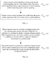
- FIG 2 is a flowchart of a power control method according to Embodiment 1 of the present invention, where the method is executed by user equipment UE. As shown in FIG 2 , the method includes the following steps.
- Step 101 Obtain a power control parameter for a sounding reference signal SRS, where the power control parameter for the SRS includes at least one of a target power parameter value for the SRS, a path loss compensation factor, and a closed-loop power control parameter value for the SRS.
- the UE may obtain the power control parameter for the SRS in different manners.
- a base station transmits a preconfigured power control parameter for the SRS to the UE by using a switching-from or switched-to carrier for SRS transmission.
- the base station sends a target power parameter value for the SRS and a path loss compensation factor to the UE by using physical layer signaling or control signaling, and then indicates a closed-loop power control parameter value for the SRS to the UE by using transmission power control (Transmission power control, TPC) information.
- TPC transmission power control
- various values in the power control parameter for the SRS may be obtained in other manners.
- Step 102 Determine transmit power for the SRS on a first carrier based on the power control parameter for the SRS.
- the first carrier is a switched-to carrier after SRS-based carrier switching, and also referred to as a non-uplink carrier, in order that SRS transmission is performed on the carrier.
- the UE may calculate the transmit power for the SRS on the first carrier based on the power control parameter for the SRS, so that the SRS is sent on the first carrier at appropriate transmit power.
- the UE obtains the power control parameter for the SRS, where the power control parameter includes at least one of the target power parameter value for the SRS, the path loss compensation factor, and the closed-loop power control parameter value for the SRS, and determines the transmit power for the SRS on the first carrier based on the power control parameter for the SRS.
- the UE can calculate transmit power for the SRS on a switched-to carrier based on a newly configured power control parameter for the SRS, so that the SRS is transmitted at optimal transmit power on a switched-to carrier, ensuring that the SRS is received correctly.
- the first carrier is a carrier on which no physical uplink shared channel (Physical Uplink Shared Channel, PUSCH for short) is sent. That is, the first carrier is used for SRS sending, but not for PUSCH sending.
- Physical Uplink Shared Channel Physical Uplink Shared Channel
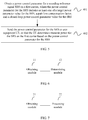
- FIG 3 is a flowchart of a power control method according to Embodiment 2 of the present invention, and the method shown in FIG 3 is a specific implementation process of step 101. As shown in FIG 3 , the method includes the following steps.
- Step 201 Receive power control signaling or cross-carrier power control signaling sent by a base station, where the power control signaling includes open-loop power control signaling and/or closed-loop power control signaling.
- the base station may deliver the power control signaling to UE by using power control signaling on a switched-to carrier to UE, or may indicate the power control signaling to the UE by using the cross-carrier power control signaling.
- the cross-carrier power control signaling includes signaling that is received on a switching-from carrier on which the SRS is located or any carrier other than the switched-to carrier, and that is used for notification about related power configuration for SRS transmission on the switched-to carrier after SRS-based carrier switching.
- the cross-carrier power control signaling is signaling sent by the base station on a switching-from carrier or any carrier other than the switched-to carrier, and the signaling includes the power control parameter for the SRS on the switched-to carrier.
- the open-loop power control signaling may include the target power parameter value for the SRS and the path loss compensation factor.
- the closed-loop power control signaling may include the target power parameter value for the SRS, the path loss compensation factor, and the closed-loop power control parameter value for the SRS.
- the power control signaling or the cross-carrier power control signaling includes radio resource control (Radio Resource Control, RRC) signaling or physical layer signaling.
- RRC Radio Resource Control
- Step 202 Obtain the power control parameter for the SRS from the power control signaling or the cross-carrier power control signaling.
- the UE parses the power control signaling or the cross-carrier power control signaling, to obtain the power control parameter for the SRS.
- the target power parameter value for the SRS is a parameter value obtained based on a preamble initial received target power value; or the target power parameter value for the SRS is a parameter value obtained based on a preamble initial received target power value and a power adjustment value.
- the base station may send the preamble initial received target power value to the UE by using the power control signaling or the cross-carrier power control signaling, and the UE calculates the target power parameter value for the SRS based on the preamble initial received target power value.
- the base station may calculate the target power parameter value for the SRS by adding the preamble initial received target power value and the power adjustment value, and then send the calculated target power parameter value for the SRS to the UE by using the power control signaling or the cross-carrier power control signaling.
- the power adjustment value may alternatively be obtained from a response message of a specially defined random access channel (Random Access Channel, RACH for short).
- the power adjustment value is also referred to as a power offset or a power offset (power offset).
- the obtaining the power control parameter from the power control signaling or the cross-carrier control signaling includes: parsing out the power control parameter for the SRS from the power control signaling or the cross-carrier power control signaling based on a first radio network temporary identifier (Radio Network Temporary Identity, RNTI for short).
- RNTI Radio Network Temporary Identity
- the first RNTI is different from a prior-art TPC-RNTI.
- the first RNTI is an RNTI that is redefined in this application, and the first RNTI may be named TPC-SRS-RNTI.
- the first RNTI is used to scramble (scramble) or mask (mask) the power control parameter for the SRS, and the scrambled parameter is carried in the physical layer signaling for indication to the UE.
- the UE receives the power control signaling or the cross-carrier power control signaling sent by the base station, and obtains the power control parameter for the SRS from the power control signaling or the cross-carrier power control signaling.
- the base station may indicate the power control parameter for the SRS to the UE by using RRC signaling, MAC signaling, or physical layer signaling, and may further scramble the power control parameter for the SRS by using the newly defined RNTI.
- the base station indicates the power control parameter for the SRS to the UE in different manners. The method is flexible, and features ease of operation.
- the determining transmit power for the SRS based on the power control parameter for the SRS includes: obtaining the transmit power for the SRS based on at least one of maximum transmit power of the user equipment UE, a transmit power adjustment value for the SRS, transmission bandwidth for the SRS, the target power parameter value for the SRS, the path loss compensation factor, and an estimated downlink path loss value.
- P CMAX , c1 ( i ) is maximum transmit power of the user equipment UE in an i th subframe
- P SRS_OFFSET,c1 ( m ) is the transmit power adjustment value for the SRS, where m equals 0 or 1
- M SRS,c1 is the transmission bandwidth for the SRS
- P O_SRS,c1 ( j ) is the target power parameter value for the SRS, where
- ⁇ SRS,c 1 ( j ) may be fixed to 1, and for P O-SRS,c1 ( j ) , usually j equals 2.
- P O_SRS,c1 ( j ) is a semi-persistent scheduling transmit power
- P O_SRS,c1 ( j ) is a dynamic scheduling transmit power
- P O_SRS,c1 ( j ) is a random access scheduling transmit power.
- the method further includes: determining whether the SRS is configured periodically or configured aperiodically.
- the UE may determine whether the SRS is configured periodically or configured aperiodically, and then determine the transmit power for the SRS based on a periodical configuration characteristic of the SRS and the power control parameter for the SRS, to ensure that the SRS can be received correctly in various circumstances.
- the closed-loop power control parameter value for the SRS is an absolute value or a relative adjustment value.
- the absolute value may be directly used to calculate the transmit power for the SRS; if the closed-loop power control parameter value for the SRS is a relative adjustment value, the closed-loop power control parameter value for the SRS needs to be calculated first based on the relative adjustment value, and then the closed-loop power control parameter value for the SRS obtained through calculation is used to calculate the transmit power for the SRS.
- the method further includes: determining the closed-loop power control parameter value for the SRS based on at least one of closed-loop power control information or a relative adjustment value for an SRS in a previous subframe.
- the determining transmit power for the SRS based on the power control parameter for the SRS includes: obtaining the transmit power for the SRS based on at least one of maximum transmit power of the user equipment UE, a transmit power adjustment value for the SRS, transmission bandwidth for the SRS, the target power parameter value for the SRS, the path loss compensation factor, an estimated downlink path loss value, and the closed-loop power control parameter for the SRS.
- ⁇ SRS,c 1 ( j ) may be fixed to 1, and for P O-SRS,c1 ( j ), usually j equals 2.
- P O_SRS,c1 ( j ) is a semi-persistent scheduling transmit power
- P O_SRS,c1 ( j ) is a dynamic scheduling transmit power
- P O-SRS,c1 ( j ) is a random access scheduling transmit power.
- the method further includes: obtaining transmission power control TPC information, where the TPC information is information scrambled or masked with the first RNTI.
- the obtaining the power control parameter for the SRS includes: parsing out the closed-loop power control parameter value for the SRS from the TPC information based on the first RNTI.
- the closed-loop power control parameter value for the SRS may be included in the TPC information scrambled with the first RNTI, and the first RNTI is indicated to the UE in advance.
- the UE may descramble the TPC information based on the first RNTI, to obtain the closed-loop power control parameter value for the SRS.
- the method further includes: obtaining downlink control information (Downlink Control Information, DCI for short).
- DCI Downlink Control Information
- the obtaining the power control parameter for the SRS includes: obtaining the closed-loop power control parameter value for the SRS based on the DCI.
- a first DCI format if the DCI is control information obtained on a second carrier, the DCI includes at least a first carrier index, where the second carrier is a switching-from carrier or any carrier other than a switched-to carrier, and the first carrier is the switched-to carrier.
- the obtaining the closed-loop power control parameter value for the SRS based on the DCI includes: obtaining the closed-loop power control parameter value for the SRS on a carrier corresponding to the first carrier index.
- DCI obtained on a switching-from carrier needs to include at least an index of a switched-to carrier, so that the UE obtains, based on the first carrier index, the closed-loop power control parameter value for the SRS on a carrier corresponding to the carrier index.
- a second DCI format if the DCI is control information obtained on the first carrier, the obtaining the closed-loop power control parameter value for the SRS based on the DCI includes: obtaining the closed-loop power control parameter value for the SRS from the DCI.
- the closed-loop power control parameter value for the SRS in the new DCI format is used directly to perform SRS transmission power control.
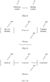
- FIG 4 is a flowchart of a power control method according to Embodiment 3 of the present invention.
- the method relates to how power control is performed when SRS-based carrier switching is triggered, if symbols of two subframes overlap and transmit power in an overlapping portion exceeds maximum transmit power of UE. As shown in FIG. 4 , the method includes the following steps.
- Step 301 Obtain transmit power in a symbol overlapping portion of a first subframe and a second subframe, where the first subframe is a subframe in which a sounding reference signal SRS is transmitted on a first carrier, and the second subframe is a subframe in which an SRS or a physical channel is transmitted on a second carrier.
- the transmit power in the symbol overlapping portion needs to be calculated.
- TAG Timing Advance Group
- Step 302 If the transmit power is greater than maximum transmit power of UE, control transmit power for a to-be-transmitted signal, where the to-be-transmitted signal includes the SRS and/or the physical channel.
- the transmit power for the to-be-transmitted signal is controlled. For example, if the transmit power is greater than the maximum transmit power of the UE, a portion of the to-be-transmitted signal is appropriately dropped, or power scaling is performed on the to-be-transmitted signal.
- the UE obtains the transmit power in the symbol overlapping portion of the first subframe in which the sounding reference signal SRS is transmitted on the first carrier and the second subframe in which the SRS or the physical channel is transmitted on the second carrier, and if the transmit power is greater than the maximum transmit power of the UE, controls the transmit power for the to-be-transmitted signal, so that the to-be-transmitted signal is transmitted at appropriate power, ensuring transmission efficiency of the to-be-transmitted signal.
- the method before the controlling transmit power for a to-be-transmitted signal, the method further includes: determining whether the SRS is configured periodically or configured aperiodically.
- controlling transmit power for a to-be-transmitted signal includes: controlling the transmit power for the to-be-transmitted signal based on a periodical configuration of the SRS; or controlling the transmit power for the to-be-transmitted signal based on an aperiodical configuration of the SRS.
- dropping a portion of the to-be-transmitted signal or performing power scaling for a portion of the to-be-transmitted signal may be selected based on a periodical characteristic of the SRS.
- the controlling transmit power for a to-be-transmitted signal includes: dropping the SRS or performing power scaling for the SRS.
- the controlling transmit power for a to-be-transmitted signal includes: dropping the PUSCH or performing power scaling for the PUSCH.
- the controlling transmit power for a to-be-transmitted signal includes: dropping the SRS or performing power scaling for the SRS.
- the controlling transmit power for a to-be-transmitted signal includes: dropping the SRS or performing power scaling for the SRS; or dropping the PUCCH or performing power scaling for the PUCCH.
- the controlling transmit power for a to-be-transmitted signal includes: dropping the SRS or performing power scaling for the SRS.
- the controlling transmit power for a to-be-transmitted signal includes: dropping the SRS or performing power scaling for the SRS; or dropping the PUCCH or performing power scaling for the PUCCH.
- the controlling transmit power for a to-be-transmitted signal includes: dropping the SRS or performing power scaling for the SRS; or dropping the PUCCH or performing power scaling for the PUCCH.
- the controlling transmit power for a to-be-transmitted signal includes: dropping the SRS or performing power scaling for the SRS.
- the following describes the method of "controlling the transmit power for the to-be-transmitted signal based on a periodical characteristic of the SRS" in detail based on different UE configurations.
- FIG 5 is a flowchart of a power control method according to Embodiment 4 of the present invention. The method is executed by a base station. As shown in FIG 5 , the method includes the following steps.
- Step 401 Obtain a power control parameter for a sounding reference signal SRS on a first carrier, where the power control parameter for the SRS includes at least one of a target power parameter value for the SRS, a path loss compensation factor, and a closed-loop power control parameter value for the SRS.
- the power control parameter for the SRS is specially configured, in order to calculate transmit power for the SRS on a switched-to carrier.
- Step 402 Send the power control parameter for the SRS to user equipment UE, so that the UE determines transmit power for the SRS on the first carrier based on the power control parameter for the SRS.
- the base station may send the power control parameter for the SRS in different manners. For example, the base station transmits a preconfigured power control parameter for the SRS to the UE by using a switched-to carrier for SRS transmission. Alternatively, the base station sends a target power parameter value for the SRS and a path loss compensation factor to the UE by using physical layer signaling or control signaling, and then indicates a closed-loop power control parameter value for the SRS to the UE by using transmission power control (Transmission power control, TPC) information. Alternatively, the base station sends various values in the power control parameter for the SRS to the UE in other manners. The UE may calculate the transmit power for the SRS on the first carrier based on the power control parameter for the SRS, so that the SRS is sent on the first carrier at appropriate transmit power.
- TPC transmission power control
- the base station obtains the power control parameter for the SRS on the first carrier, where the power control parameter includes at least one of the target power parameter value for the SRS, the path loss compensation factor, and the closed-loop power control parameter value for the SRS, sends the power control parameter for the SRS to the user equipment UE, so that the UE determines the transmit power for the SRS on the first carrier based on the power control parameter for the SRS.
- the UE can calculate transmit power for the SRS on a switched-to carrier based on a newly configured power control parameter for the SRS, so that the SRS is transmitted on the switched-to carrier at optimal transmit power, ensuring that the SRS is received correctly.
- the first carrier is a carrier on which no PUSCH is sent.
- the sending the power control parameter for the SRS to user equipment UE includes: sending the power control parameter for the SRS to the UE by using power control signaling or cross-carrier power control signaling.
- the power control signaling includes open-loop power control signaling and/or closed-loop power control signaling.
- the power control signaling or the cross-carrier power control signaling includes radio resource control RRC signaling or physical layer signaling.
- the target power parameter value for the SRS is a parameter value obtained based on a preamble initial received target power value; or the target power parameter value for the SRS is a parameter value obtained based on a preamble initial received target power value and a power adjustment value.
- the sending the power control parameter for the SRS to the UE by using power control signaling or cross-carrier power control signaling includes: scrambling the power control parameter for the SRS based on a first radio network temporary identifier RNTI, to generate the power control signaling or the cross-carrier power control signaling; and sending the power control signaling or the cross-carrier power control signaling to the UE.
- the SRS is configured periodically or configured aperiodically.
- the closed-loop power control parameter value for the SRS is an absolute value or a relative adjustment value.
- the method further includes: sending TPC information to the UE, so that the UE parses out the closed-loop power control parameter value for the SRS from the TPC information, where the TPC information is information scrambled with the first radio network temporary identifier RNTI.
- the method further includes: sending downlink control information DCI to the UE, so that the UE obtains the closed-loop power control parameter value for the SRS based on the DCI.
- the DCI is control information obtained on a second carrier
- the DCI includes at least a first carrier index
- the DCI is used to instruct the UE to obtain the closed-loop power control parameter value for the SRS on a carrier corresponding to the first carrier index.
- the second carrier is a switching-from carrier or any carrier other than a switched-to carrier, and the first carrier is the switched-to carrier.
- the DCI is used to instruct the UE to obtain the closed-loop power control parameter value for the SRS from the DCI.
- the power control method provided in this embodiment is implemented by a base station and is corresponding to the UE-side power control method.
- a base station is corresponding to the UE-side power control method.
- the UE-side power control method in the embodiments in FIG 2 to Fig. 4 . Details are not described herein again.
- FIG 6 is a structural diagram of a power control apparatus according to Embodiment 5 of the present invention.
- the apparatus includes an obtaining module 11 and a determining module 12.
- the obtaining module 11 is configured to obtain a power control parameter for a sounding reference signal SRS, where the power control parameter for the SRS includes at least one of a target power parameter value for the SRS, a path loss compensation factor, and a closed-loop power control parameter value for the SRS.
- the determining module 12 is configured to determine transmit power for the SRS on a first carrier based on the power control parameter for the SRS.
- the apparatus in this embodiment may be configured to execute the technical solution of the method embodiment shown in FIG 2 .
- Their implementation principles and technical effects are similar, and no more details are provided herein.
- the first carrier is a carrier on which no physical uplink shared channel PUSCH is sent.
- the obtaining module 11 is specifically configured to obtain power control signaling or cross-carrier power control signaling sent by a base station.
- the power control signaling includes open-loop power control signaling and/or closed-loop power control signaling.
- the obtaining module 11 is specifically further configured to obtain the power control parameter for the SRS from the power control signaling or the cross-carrier power control signaling.
- the power control signaling or the cross-carrier power control signaling includes radio resource control RRC signaling or physical layer signaling.
- the target power parameter value for the SRS is a parameter value obtained based on a preamble initial received target power value; or the target power parameter value for the SRS is a parameter value obtained based on a preamble initial received target power value and a power adjustment value.
- the obtaining module 11 obtains the power control parameter from the power control signaling or the cross-carrier power control signaling includes that the obtaining module 11 parses out the power control parameter for the SRS from the power control signaling or the cross-carrier power control signaling based on a first radio network temporary identifier RNTI.
- the determining module 12 is specifically configured to obtain the transmit power for the SRS based on at least one of maximum transmit power of user equipment UE, a transmit power adjustment value for the SRS, transmission bandwidth for the SRS, the target power parameter value for the SRS, the path loss compensation factor, and an estimated downlink path loss value.
- the determining module 12 is further configured to determine whether the SRS is configured periodically or configured aperiodically.
- the closed-loop power control parameter value for the SRS is an absolute value or a relative adjustment value.
- the obtaining module 11 is further configured to obtain transmission power control TPC information, where the TPC information is information scrambled with the first radio network temporary identifier RNTI.
- the obtaining module 11 obtains the power control parameter for the SRS includes that the obtaining module 11 parses out the closed-loop power control parameter value for the SRS from the TPC information based on the first RNTI.
- the obtaining module 11 is further configured to obtain downlink control information DCI.
- that the obtaining module 11 obtains the power control parameter for the SRS includes that the obtaining module 11 obtains the closed-loop power control parameter value for the SRS based on the DCI.
- the DCI includes at least a first carrier index.
- the second carrier is a switching-from carrier or any carrier other than a switched-to carrier
- the first carrier is the switched-to carrier
- that the obtaining module 11 obtains the closed-loop power control parameter value for the SRS based on the DCI includes that the obtaining module 11 obtains the closed-loop power control parameter value for the SRS on a carrier corresponding to the first carrier index.
- that the obtaining module 11 obtains the closed-loop power control parameter value for the SRS based on the DCI includes that the obtaining module 11 obtains the closed-loop power control parameter value for the SRS from the DCI.
- the determining module 12 is further configured to determine the closed-loop power control parameter value for the SRS based on at least one of closed-loop power control information or a relative adjustment value for an SRS in a previous subframe.
- the determining module 12 determines transmit power for the SRS based on the power control parameter for the SRS includes that the determining module 12 obtains the transmit power for the SRS based on at least one of maximum transmit power of the user equipment UE, a transmit power adjustment value for the SRS, transmission bandwidth for the SRS, the target power parameter value for the SRS, the path loss compensation factor, the estimated downlink path loss value, and a closed-loop power control parameter for the SRS.
- the apparatus in this embodiment may be configured to execute the technical solution of the method embodiment shown in FIG 2 or FIG 3 .
- Their implementation principles and technical effects are similar, and no more details are provided herein.
- FIG 7 is a structural diagram of a power control apparatus according to Embodiment 6 of the present invention.
- the apparatus includes an obtaining module 21 and a processing module 22.
- the obtaining module 21 is configured to obtain transmit power in a symbol overlapping portion of a first subframe and a second subframe, where the first subframe is a subframe in which a sounding reference signal SRS is transmitted on a first carrier, and the second subframe is a subframe in which an SRS or a physical channel is transmitted on a second carrier.
- the processing module 22 is configured to, if the transmit power is greater than maximum transmit power of user equipment UE, control transmit power for a to-be-transmitted signal, where the to-be-transmitted signal includes the SRS and/or the physical channel.
- the processing module 22 is further configured to determine whether the SRS is configured periodically or configured aperiodically.
- processing module 22 controls transmit power for a to-be-transmitted signal includes that the processing module 22 controls the transmit power for the to-be-transmitted signal based on a periodical configuration of the SRS; or that the processing module 22 controls the transmit power for the to-be-transmitted signal based on an aperiodical configuration of the SRS.
- that the processing module 22 controls transmit power for a to-be-transmitted signal includes that the processing module 22 drops the SRS or performs power scaling for the SRS.
- the physical channel is a physical uplink shared channel PUSCH
- the PUSCH does not include uplink control information UCI
- that the processing module 22 controls transmit power for a to-be-transmitted signal includes that the processing module 22 drops the PUSCH or performs power scaling for the PUSCH.
- the physical channel is a physical uplink shared channel PUSCH, and the PUSCH includes uplink control information UCI, that the processing module 22 controls transmit power for a to-be-transmitted signal includes that the processing module 22 drops the SRS or performs power scaling for the SRS.
- the processing module 22 controls transmit power for a to-be-transmitted signal includes that the processing module 22 drops the SRS or performs power scaling for the SRS; or that the processing module 22 drops the PUCCH or performs power scaling for the PUCCH.
- the physical channel is a physical uplink control channel PUCCH
- the PUCCH includes a hybrid automatic repeat request HARQ
- that the processing module 22 controls transmit power for a to-be-transmitted signal includes that the processing module 22 drops the SRS or performs power scaling for the SRS.
- the physical channel is a physical uplink control channel PUCCH, and the PUCCH includes only channel state information CSI, that the processing module 22 controls transmit power for a to-be-transmitted signal that the processing module 22 drops the SRS or performs power scaling for the SRS; or that the processing module 22 drops the PUCCH or performs power scaling for the PUCCH.
- the processing module 22 controls transmit power for a to-be-transmitted signal includes that the processing module 22 drops the SRS or performs power scaling for the SRS.
- the apparatus in this embodiment may be configured to execute the technical solution of the method embodiment shown in FIG 4 .
- Their implementation principles and technical effects are similar, and no more details are provided herein.
- FIG 8 is a structural diagram of a power control apparatus according to Embodiment 7 of the present invention.
- the apparatus includes an obtaining module 31 and a sending module 32.
- the obtaining module 31 is configured to obtain a power control parameter for a sounding reference signal SRS on a first carrier, where the power control parameter for the SRS includes at least one of a target power parameter value for the SRS, a path loss compensation factor, and a closed-loop power control parameter value for the SRS.
- the sending module 32 is configured to send the power control parameter for the SRS to user equipment UE, so that the UE determines transmit power for the SRS on the first carrier based on the power control parameter for the SRS.
- the first carrier is a carrier on which no physical uplink shared channel PUSCH is sent.
- the sending module is specifically configured to send the power control parameter for the SRS to the UE by using power control signaling or cross-carrier power control signaling.
- the power control signaling includes open-loop power control signaling and/or closed-loop power control signaling.
- the power control signaling or the cross-carrier power control signaling includes radio resource control RRC signaling or physical layer signaling.
- the target power parameter value for the SRS is a parameter value obtained based on a preamble initial received target power value; or the target power parameter value for the SRS is a parameter value obtained based on a preamble initial received target power value and a power adjustment value.
- the sending module sends the power control parameter for the SRS to the UE by using power control signaling or cross-carrier power control signaling includes that the sending module scrambles the power control parameter for the SRS based on a first radio network temporary identifier RNTI, to generate the power control signaling or the cross-carrier power control signaling; and sends the power control signaling or the cross-carrier power control signaling to the UE.
- the SRS is configured periodically or configured aperiodically.
- the closed-loop power control parameter value for the SRS is an absolute value or a relative adjustment value.
- the sending module is further configured to send transmission power control TPC information to the UE, so that the UE parses out the closed-loop power control parameter value for the SRS from the TPC information, where the TPC information is information scrambled with the first radio network temporary identifier RNTI.
- the sending module is further configured to send downlink control information DCI to the UE, so that the UE obtains the closed-loop power control parameter value for the SRS based on the DCI.
- the DCI is control information obtained on a second carrier
- the DCI includes at least a first carrier index
- the DCI is used to instruct the UE to obtain the closed-loop power control parameter value for the SRS on a carrier corresponding to the first carrier index.
- the second carrier is a switching-from carrier or any carrier other than a switched-to carrier
- the first carrier is the switched-to carrier
- the DCI is used to instruct the UE to obtain the closed-loop power control parameter value for the SRS from the DCI.
- the apparatus in this embodiment may be configured to execute the technical solution of the method embodiment shown in FIG 5 .
- Their implementation principles and technical effects are similar, and no more details are provided herein.
- FIG 9 is a structural diagram of UE according to Embodiment 8 of the present invention.
- the UE may include a processor 401 and a memory 402.
- the apparatus may further include a transmit interface 403 and a receive interface 404.
- the transmit interface 403 and the receive interface 404 may be connected to the processor 401.
- the transmit interface 403 is used to send data or information, and the transmit interface 403 may be a radio transmitting apparatus.
- the receive interface 404 is used to receive data or information, and the receive interface 404 may be a radio receiving apparatus.
- the memory 402 stores an executable instruction. When the apparatus runs, the processor 401 communicates with the memory 402, and the processor 401 call the executable instruction in the memory 402 to perform the following operations:
- the first carrier is a carrier on which no physical uplink shared channel PUSCH is sent.
- that the processor 401 obtains a power control parameter for a sounding reference signal SRS includes that the processor 401 receives power control signaling or cross-carrier power control signaling sent by a base station.
- the power control signaling includes open-loop power control signaling and/or closed-loop power control signaling.
- that the processor 401 obtains a power control parameter for a sounding reference signal SRS includes that the processor 401 obtains the power control parameter for the SRS from the power control signaling or the cross-carrier power control signaling.
- the power control signaling or the cross-carrier power control signaling includes radio resource control RRC signaling or physical layer signaling.
- the target power parameter value for the SRS is a parameter value obtained based on a preamble initial received target power value; or the target power parameter value for the SRS is a parameter value obtained based on a preamble initial received target power value and a power adjustment value.
- that the processor 401 obtains the power control parameter from the power control signaling or the cross-carrier power control signaling includes that the processor 401 parses out the power control parameter for the SRS from the power control signaling or the cross-carrier power control signaling based on a first radio network temporary identifier RNTI.
- the processor 401 determines transmit power for the SRS based on the power control parameter for the SRS includes that the processor 401 obtains the transmit power for the SRS based on at least one of maximum transmit power of user equipment UE, a transmit power adjustment value for the SRS, transmission bandwidth for the SRS, the target power parameter value for the SRS, the path loss compensation factor, and an estimated downlink path loss value.
- the processor 401 is further configured to determine whether the SRS is configured periodically or configured aperiodically.
- the closed-loop power control parameter value for the SRS is an absolute value or a relative adjustment value.
- the processor 401 is further configured to obtain transmission power control TPC information, where the TPC information is information scrambled with the first radio network temporary identifier RNTI.
- the processor 401 is further configured to parse out the closed-loop power control parameter value for the SRS from the TPC information based on the first RNTI.
- the processor 401 is further configured to obtain downlink control information DCI.
- that the processor 401 obtains the power control parameter for the SRS includes that the processor 401 obtains the closed-loop power control parameter value for the SRS based on the DCI.
- the DCI includes at least a first carrier index.
- the second carrier is a switching-from carrier or any carrier other than a switched-to carrier
- the first carrier is the switched-to carrier
- that the processor 401 obtains the closed-loop power control parameter value for the SRS based on the DCI includes that the processor 401 obtains the closed-loop power control parameter value for the SRS on a carrier corresponding to the first carrier index.
- that the processor 401 obtains the closed-loop power control parameter value for the SRS based on the DCI includes that the processor 401 obtains the closed-loop power control parameter value for the SRS from the DCI.
- the processor 401 is further configured to determine the closed-loop power control parameter value for the SRS based on at least one of closed-loop power control information or a relative adjustment value for an SRS in a previous subframe.
- the processor 401 determines transmit power for the SRS based on the power control parameter for the SRS includes that the processor 401 obtains the transmit power for the SRS based on at least one of maximum transmit power of the user equipment UE, a transmit power adjustment value for the SRS, transmission bandwidth for the SRS, the target power parameter value for the SRS, the path loss compensation factor, the estimated downlink path loss value, and a closed-loop power control parameter for the SRS.
- the UE in this embodiment may be configured to execute the technical solution of the method embodiment shown in FIG 2 or FIG 3 . Their implementation principles and technical effects are similar, and no more details are provided herein.
- An embodiment of this application further provides UE, where a structure of the UE is the same as a structure of the UE shown in FIG 9 .
- a processor communicates with a memory, and the processor calls an executable instruction in the memory to perform the following operations:
- the processor is further configured to determine whether the SRS is configured periodically or configured aperiodically.
- the processor controls transmit power for a to-be-transmitted signal includes that the processor controls the transmit power for the to-be-transmitted signal based on a periodical configuration of the SRS; or that the processor controls the transmit power for the to-be-transmitted signal based on an aperiodical configuration of the SRS.
- that the processor controls transmit power for a to-be-transmitted signal includes that dropping the SRS or performing power scaling for the SRS.
- the physical channel is a physical uplink shared channel PUSCH
- the PUSCH does not include uplink control information UCI
- that the processor controls transmit power for a to-be-transmitted signal includes that the processor drops the PUSCH or performs power scaling for the PUSCH.
- the physical channel is a physical uplink shared channel PUSCH
- the PUSCH includes uplink control information UCI
- that the processor controls transmit power for a to-be-transmitted signal includes that the processor drops the SRS or performs power scaling for the SRS.
- the processor controls transmit power for a to-be-transmitted signal includes that the processor drops the SRS or performs power scaling for the SRS; or that the processor drops the PUCCH or performs power scaling for the PUCCH.
- the physical channel is a physical uplink control channel PUCCH
- the PUCCH includes a hybrid automatic repeat request HARQ
- that the processor controls transmit power for a to-be-transmitted signal includes that the processor drops the SRS or performs power scaling for the SRS.
- the physical channel is a physical uplink control channel PUCCH
- the PUCCH includes only channel state information CSI
- that the processor controls transmit power for a to-be-transmitted signal includes that the processor drops the SRS or performs power scaling for the SRS; or that the processor drops the PUCCH or performs power scaling for the PUCCH.
- the processor controls transmit power for a to-be-transmitted signal includes that the processor drops the SRS or performs power scaling for the SRS.
- the UE in this embodiment may be configured to execute the technical solution of the method embodiment shown in FIG 4 .
- Their implementation principles and technical effects are similar, and no more details are provided herein.
- FIG 10 is a structural diagram of a base station according to Embodiment 9 of the present invention.
- the base station includes a processor 501 and a transmitter 502.
- the processor 501 is configured to obtain a power control parameter for a sounding reference signal SRS on a first carrier, where the power control parameter for the SRS includes at least one of a target power parameter value for the SRS, a path loss compensation factor, and a closed-loop power control parameter value for the SRS.
- the transmitter 502 is configured to send the power control parameter for the SRS to user equipment UE, so that the UE determines transmit power for the SRS on the first carrier based on the power control parameter for the SRS.
- the first carrier is a carrier on which no physical uplink shared channel PUSCH is sent.
- that the transmitter 502 sends the power control parameter for the SRS to user equipment UE includes that the transmitter 502 sends the power control parameter for the SRS to the UE by using power control signaling or cross-carrier power control signaling.
- the power control signaling includes open-loop power control signaling and/or closed-loop power control signaling.
- the power control signaling or the cross-carrier power control signaling includes radio resource control RRC signaling or physical layer signaling.
- the target power parameter value for the SRS is a parameter value obtained based on a preamble initial received target power value; or the target power parameter value for the SRS is a parameter value obtained based on a preamble initial received target power value and a power adjustment value.
- that the transmitter 502 sends the power control parameter for the SRS to the UE by using power control signaling or cross-carrier power control signaling includes that the transmitter 502 scrambles the power control parameter for the SRS based on an RNTI, to generate the power control signaling or the cross-carrier power control signaling; and sending the power control signaling or the cross-carrier power control signaling to the UE.
- the SRS is configured periodically or configured aperiodically.
- the closed-loop power control parameter value for the SRS is an absolute value or a relative adjustment value.
- the transmitter 502 is further configured to send transmission power control TPC information to the UE, so that the UE parses out the closed-loop power control parameter value for the SRS from the TPC information, where the TPC information is information scrambled with the first radio network temporary identifier RNTI.
- the transmitter 502 is further configured to send downlink control information DCI to the UE, so that the UE obtains the closed-loop power control parameter value for the SRS based on the DCI.
- the DCI is control information obtained on a second carrier
- the DCI includes at least a first carrier index
- the DCI is used to instruct the UE to obtain the closed-loop power control parameter value for the SRS on a carrier corresponding to the first carrier index.
- the second carrier is a switching-from carrier or any carrier other than a switched-to carrier
- the first carrier is the switched-to carrier
- the DCI is used to instruct the UE to obtain the closed-loop power control parameter value for the SRS from the DCI.
- the base station may further include a memory 503 and a receiver 504.
- the memory 503 is configured to store an instruction and data
- the receiver 504 is configured to receive data or information.
- the apparatus in this embodiment may be configured to execute the technical solution of the method embodiment shown in FIG 5 .
- Their implementation principles and technical effects are similar, and no more details are provided herein.
- the program may be stored in a computer-readable storage medium.
- the foregoing storage medium includes: any medium that can store program code, such as a read-only memory (Read-Only Memory, ROM for short), a random access memory (random access memory, RAM for short), a magnetic disk, or an optical disc.
- the invention also provides the following embodiments. It should be noted that the numbering of the following embodiments does not necessarily need to follow the numbering order of the previous embodiments:
Landscapes
- Engineering & Computer Science (AREA)
- Signal Processing (AREA)
- Computer Networks & Wireless Communication (AREA)
- Mobile Radio Communication Systems (AREA)
- Charge And Discharge Circuits For Batteries Or The Like (AREA)
- Feedback Control In General (AREA)
Priority Applications (3)
| Application Number | Priority Date | Filing Date | Title |
|---|---|---|---|
| ES20200054T ES2935186T3 (es) | 2016-05-13 | 2016-05-13 | Método y dispositivo de control de potencia |
| EP22188692.2A EP4152837B1 (de) | 2016-05-13 | 2016-05-13 | Leistungssteuerungsverfahren und -vorrichtung |
| EP20200054.3A EP3843466B1 (de) | 2016-05-13 | 2016-05-13 | Leistungssteuerungsverfahren und -vorrichtung |
Applications Claiming Priority (3)
| Application Number | Priority Date | Filing Date | Title |
|---|---|---|---|
| EP16901353.9A EP3454608B1 (de) | 2016-05-13 | 2016-05-13 | Leistungssteuerungsverfahren und -vorrichtung |
| PCT/CN2016/082122 WO2017193398A1 (zh) | 2016-05-13 | 2016-05-13 | 功率控制方法和装置 |
| EP20200054.3A EP3843466B1 (de) | 2016-05-13 | 2016-05-13 | Leistungssteuerungsverfahren und -vorrichtung |
Related Parent Applications (2)
| Application Number | Title | Priority Date | Filing Date |
|---|---|---|---|
| EP16901353.9A Division-Into EP3454608B1 (de) | 2016-05-13 | 2016-05-13 | Leistungssteuerungsverfahren und -vorrichtung |
| EP16901353.9A Division EP3454608B1 (de) | 2016-05-13 | 2016-05-13 | Leistungssteuerungsverfahren und -vorrichtung |
Related Child Applications (2)
| Application Number | Title | Priority Date | Filing Date |
|---|---|---|---|
| EP22188692.2A Division EP4152837B1 (de) | 2016-05-13 | 2016-05-13 | Leistungssteuerungsverfahren und -vorrichtung |
| EP22188692.2A Division-Into EP4152837B1 (de) | 2016-05-13 | 2016-05-13 | Leistungssteuerungsverfahren und -vorrichtung |
Publications (3)
| Publication Number | Publication Date |
|---|---|
| EP3843466A2 true EP3843466A2 (de) | 2021-06-30 |
| EP3843466A3 EP3843466A3 (de) | 2021-07-21 |
| EP3843466B1 EP3843466B1 (de) | 2022-10-26 |
Family
ID=60266023
Family Applications (3)
| Application Number | Title | Priority Date | Filing Date |
|---|---|---|---|
| EP20200054.3A Active EP3843466B1 (de) | 2016-05-13 | 2016-05-13 | Leistungssteuerungsverfahren und -vorrichtung |
| EP22188692.2A Active EP4152837B1 (de) | 2016-05-13 | 2016-05-13 | Leistungssteuerungsverfahren und -vorrichtung |
| EP16901353.9A Active EP3454608B1 (de) | 2016-05-13 | 2016-05-13 | Leistungssteuerungsverfahren und -vorrichtung |
Family Applications After (2)
| Application Number | Title | Priority Date | Filing Date |
|---|---|---|---|
| EP22188692.2A Active EP4152837B1 (de) | 2016-05-13 | 2016-05-13 | Leistungssteuerungsverfahren und -vorrichtung |
| EP16901353.9A Active EP3454608B1 (de) | 2016-05-13 | 2016-05-13 | Leistungssteuerungsverfahren und -vorrichtung |
Country Status (9)
| Country | Link |
|---|---|
| US (4) | US10506520B2 (de) |
| EP (3) | EP3843466B1 (de) |
| JP (1) | JP6710781B2 (de) |
| KR (2) | KR102376071B1 (de) |
| CN (2) | CN109640385B (de) |
| AU (1) | AU2016406586B2 (de) |
| ES (1) | ES2935186T3 (de) |
| RU (1) | RU2701380C1 (de) |
| WO (1) | WO2017193398A1 (de) |
Families Citing this family (25)
| Publication number | Priority date | Publication date | Assignee | Title |
|---|---|---|---|---|
| CN108365930B (zh) * | 2017-01-26 | 2021-08-31 | 华为技术有限公司 | 上行测量参考信号的功率控制方法、网络设备及终端设备 |
| CN113411876B (zh) | 2017-05-05 | 2022-10-04 | 华为技术有限公司 | 上行链路传输的功率控制方法 |
| WO2018230901A1 (ko) | 2017-06-15 | 2018-12-20 | 삼성전자 주식회사 | 빔포밍 시스템에서 단말의 송신 전력 제어 방법 및 장치 |
| KR102379822B1 (ko) * | 2017-06-15 | 2022-03-30 | 삼성전자 주식회사 | 빔포밍 시스템에서 단말의 송신 전력 제어 방법 및 장치 |
| CN112867121B (zh) | 2018-01-12 | 2022-06-10 | 中兴通讯股份有限公司 | 一种功率控制方法、第一通信节点和第二通信节点 |
| CN110049539A (zh) * | 2018-01-16 | 2019-07-23 | 维沃移动通信有限公司 | 上行功率控制参数配置方法、终端及网络设备 |
| CN110351040B (zh) * | 2018-04-03 | 2020-08-14 | 维沃移动通信有限公司 | 探测参考信号传输、配置方法、用户设备及网络侧设备 |
| US11350416B2 (en) * | 2018-07-20 | 2022-05-31 | Qualcomm Incorporated | Physical uplink control channel repetition configuration |
| CN110859004B (zh) * | 2018-08-23 | 2023-12-08 | 维沃移动通信有限公司 | 用于确定物理上行共享信道发送功率的方法和设备 |
| CN110881218A (zh) * | 2018-09-05 | 2020-03-13 | 维沃移动通信有限公司 | 探测参考信号传输方法和终端设备 |
| CN110972246B (zh) * | 2018-09-28 | 2023-09-22 | 维沃移动通信有限公司 | 功率控制方法、传输功率控制参数确定方法及相关设备 |
| US11172495B2 (en) * | 2019-01-11 | 2021-11-09 | Qualcomm Incorporated | Collision handling |
| US11388723B2 (en) * | 2019-03-28 | 2022-07-12 | Ofinno, Llc | Uplink transmission in a wireless communication system |
| CN111263430B (zh) * | 2019-04-30 | 2021-11-09 | 维沃移动通信有限公司 | Srs功率控制方法和设备 |
| US11490402B2 (en) * | 2019-07-05 | 2022-11-01 | Qualcomm Incorporated | Power control based on semi-static direction for dual connectivity |
| CN111800861A (zh) | 2019-07-12 | 2020-10-20 | 维沃移动通信有限公司 | 功率控制方法及设备 |
| CN113613322B (zh) * | 2019-08-12 | 2023-06-20 | Oppo广东移动通信有限公司 | 用于确定发射功率的方法和装置 |
| CN115694770B (zh) | 2019-11-08 | 2023-10-31 | 中兴通讯股份有限公司 | 发送参数确定方法、电子装置、设备及介质 |
| EP3829076A3 (de) | 2019-11-28 | 2021-08-04 | Samsung Electronics Co., Ltd. | Sendeleistungsregelung von akustischen referenzsignalen in einem drahtlosen kommunikationssystem und vorrichtung |
| CN113596975B (zh) | 2020-04-30 | 2022-12-06 | 华为技术有限公司 | 一种上行功率控制方法及装置 |
| KR102900322B1 (ko) * | 2020-12-16 | 2025-12-16 | 삼성전자주식회사 | 전자 장치 및 전자 장치에서 기준 신호를 전송하는 방법 |
| CN116671213A (zh) | 2021-01-07 | 2023-08-29 | 华为技术有限公司 | 确定发送功率的方法及装置 |
| EP4277409A4 (de) * | 2021-05-10 | 2024-02-28 | Guangdong Oppo Mobile Telecommunications Corp., Ltd. | Trägerbestimmungsverfahren und -vorrichtung sowie vorrichtung und speichermedium |
| CN117796054A (zh) * | 2021-07-09 | 2024-03-29 | 高通股份有限公司 | 特定于波束的虚拟功率余量报告 |
| US20240098650A1 (en) * | 2022-09-16 | 2024-03-21 | Qualcomm Incorporated | Transmitting secondary cell transmissions using transmit power control adjustment values associated with a primary cell |
Family Cites Families (19)
| Publication number | Priority date | Publication date | Assignee | Title |
|---|---|---|---|---|
| AR075865A1 (es) * | 2009-03-17 | 2011-05-04 | Interdigital Patent Holdings | Metodo y aparato para control de potencia de transmision de senal de referencia de sonido (srs) |
| HUE040251T2 (hu) | 2010-04-30 | 2019-02-28 | Sun Patent Trust | Vezeték nélküli kommunikációs eszköz és eljárás adásteljesítmény szabályozására |
| KR20140038557A (ko) * | 2011-08-12 | 2014-03-28 | 후지쯔 가부시끼가이샤 | 업링크 전력 제어 방법 및 장치 |
| WO2013048143A2 (en) * | 2011-09-27 | 2013-04-04 | Samsung Electronics Co., Ltd. | A method and appratus for transmission power control for a sounding reference signal |
| CN103891166A (zh) * | 2011-09-30 | 2014-06-25 | 交互数字专利控股公司 | 无线通信中的多点传输 |
| CN103167594B (zh) | 2011-12-19 | 2015-05-27 | 华为技术有限公司 | 一种上行发射功率控制方法及用户设备 |
| WO2013114799A1 (ja) * | 2012-01-30 | 2013-08-08 | パナソニック株式会社 | 無線通信端末装置および送信電力制御方法 |
| CN103312484B (zh) | 2012-03-16 | 2017-12-29 | 中兴通讯股份有限公司 | 探测参考信号发射功率的控制方法、用户设备和基站 |
| CN103369654A (zh) * | 2012-04-09 | 2013-10-23 | 电信科学技术研究院 | 功控参数的指示及功控方法和设备 |
| JP6073073B2 (ja) * | 2012-05-10 | 2017-02-01 | シャープ株式会社 | 端末装置、基地局装置および通信方法 |
| KR20140009902A (ko) * | 2012-07-12 | 2014-01-23 | 주식회사 케이티 | 상향링크 사운딩 참조신호 전송전력 제어방법 및 그 단말, 송수신포인트 |
| SMT201800321T1 (it) * | 2012-08-01 | 2018-07-17 | Sun Patent Trust | Dispositivo terminale di comunicazione senza fili, dispositivo stazione base di comunicazione senza fili, e metodo di comunicazione senza fili |
| US10159052B2 (en) | 2012-08-03 | 2018-12-18 | Qualcomm Incorporated | Method and apparatus for sounding reference signal triggering and power control for coordinated multi-point operations |
| CN103634887B (zh) * | 2012-08-24 | 2018-03-09 | 华为技术有限公司 | 载波汇聚场景下用户设备的上行功率控制方法和装置 |
| KR102004544B1 (ko) | 2013-02-06 | 2019-07-26 | 노키아 테크놀로지스 오와이 | 무선 통신 시스템에서 채널측정 기준신호 전송 방법 및 장치 |
| US9414335B2 (en) * | 2014-02-06 | 2016-08-09 | Electronics And Telecommunications Research Instit | Method and apparatus for transmitting uplink signal or uplink channel |
| CN105099632B (zh) | 2014-04-23 | 2019-12-13 | 北京三星通信技术研究有限公司 | 一种上行探测参考信号传输的方法和设备 |
| US10547426B2 (en) | 2016-03-14 | 2020-01-28 | Samsung Electronics Co., Ltd. | Transmission of sounding reference signals in communication systems with carrier aggregation |
| US10333670B2 (en) | 2016-05-06 | 2019-06-25 | Qualcomm Incorporated | Sounding reference signals with collisions in asymmetric carrier aggregation |
-
2016
- 2016-05-13 ES ES20200054T patent/ES2935186T3/es active Active
- 2016-05-13 RU RU2018143936A patent/RU2701380C1/ru active
- 2016-05-13 EP EP20200054.3A patent/EP3843466B1/de active Active
- 2016-05-13 JP JP2018560030A patent/JP6710781B2/ja active Active
- 2016-05-13 CN CN201811432127.5A patent/CN109640385B/zh active Active
- 2016-05-13 CN CN201680030409.5A patent/CN107637143B/zh active Active
- 2016-05-13 EP EP22188692.2A patent/EP4152837B1/de active Active
- 2016-05-13 KR KR1020217009276A patent/KR102376071B1/ko active Active
- 2016-05-13 US US16/301,102 patent/US10506520B2/en active Active
- 2016-05-13 AU AU2016406586A patent/AU2016406586B2/en active Active
- 2016-05-13 EP EP16901353.9A patent/EP3454608B1/de active Active
- 2016-05-13 WO PCT/CN2016/082122 patent/WO2017193398A1/zh not_active Ceased
- 2016-05-13 KR KR1020187036269A patent/KR102235543B1/ko active Active
-
2019
- 2019-10-17 US US16/656,238 patent/US10631249B2/en active Active
-
2020
- 2020-04-08 US US16/842,922 patent/US11026179B2/en active Active
-
2021
- 2021-05-24 US US17/328,106 patent/US11419057B2/en active Active
Also Published As
| Publication number | Publication date |
|---|---|
| CN107637143A (zh) | 2018-01-26 |
| EP3454608B1 (de) | 2020-11-18 |
| EP4152837B1 (de) | 2024-09-25 |
| CN109640385A (zh) | 2019-04-16 |
| EP3454608A4 (de) | 2019-04-24 |
| AU2016406586A1 (en) | 2018-12-13 |
| US20190191382A1 (en) | 2019-06-20 |
| US11026179B2 (en) | 2021-06-01 |
| KR102235543B1 (ko) | 2021-04-01 |
| US10631249B2 (en) | 2020-04-21 |
| US11419057B2 (en) | 2022-08-16 |
| EP3454608A1 (de) | 2019-03-13 |
| JP6710781B2 (ja) | 2020-06-17 |
| BR112018073317A2 (pt) | 2019-02-19 |
| EP4152837A1 (de) | 2023-03-22 |
| AU2016406586B2 (en) | 2020-02-13 |
| WO2017193398A1 (zh) | 2017-11-16 |
| US20210352591A1 (en) | 2021-11-11 |
| CN107637143B (zh) | 2020-12-18 |
| KR102376071B1 (ko) | 2022-03-17 |
| US20200236629A1 (en) | 2020-07-23 |
| ES2935186T3 (es) | 2023-03-02 |
| KR20210037025A (ko) | 2021-04-05 |
| JP2019521575A (ja) | 2019-07-25 |
| US20200053654A1 (en) | 2020-02-13 |
| CN109640385B (zh) | 2020-03-20 |
| RU2701380C1 (ru) | 2019-09-26 |
| US10506520B2 (en) | 2019-12-10 |
| EP3843466A3 (de) | 2021-07-21 |
| EP3843466B1 (de) | 2022-10-26 |
| EP4152837C0 (de) | 2024-09-25 |
| KR20190006002A (ko) | 2019-01-16 |
Similar Documents
| Publication | Publication Date | Title |
|---|---|---|
| US11419057B2 (en) | Power control method and apparatus | |
| US10560947B2 (en) | Terminal device, network device, uplink reference signal sending method, and uplink reference signal receiving method | |
| KR20120124442A (ko) | 무선 통신 시스템, 이동국 장치, 무선 통신 방법 및 집적 회로 | |
| WO2014007581A1 (ko) | 무선 통신 시스템에서 d2d(device-to-device) 통신을 위한 전력 제어 방법 및 이를 위한 장치 | |
| EP3123647B1 (de) | Verbesserung von gruppenkommunikationsdiensten | |
| US10117189B2 (en) | Uplink power control method, user equipment, and base station | |
| CN108029111B (zh) | 终端装置以及通信方法 | |
| US20190373619A1 (en) | Radio communication method, terminal device, and network device | |
| JP6992124B2 (ja) | 電力制御方法および装置 | |
| US20250150217A1 (en) | Method and apparatus for multicast harq-ack feedback determination | |
| BR112018073317B1 (pt) | Método de controle de potência e aparelho |
Legal Events
| Date | Code | Title | Description |
|---|---|---|---|
| PUAI | Public reference made under article 153(3) epc to a published international application that has entered the european phase |
Free format text: ORIGINAL CODE: 0009012 |
|
| STAA | Information on the status of an ep patent application or granted ep patent |
Free format text: STATUS: REQUEST FOR EXAMINATION WAS MADE |
|
| PUAL | Search report despatched |
Free format text: ORIGINAL CODE: 0009013 |
|
| 17P | Request for examination filed |
Effective date: 20201005 |
|
| AC | Divisional application: reference to earlier application |
Ref document number: 3454608 Country of ref document: EP Kind code of ref document: P |
|
| AK | Designated contracting states |
Kind code of ref document: A2 Designated state(s): AL AT BE BG CH CY CZ DE DK EE ES FI FR GB GR HR HU IE IS IT LI LT LU LV MC MK MT NL NO PL PT RO RS SE SI SK SM TR |
|
| AK | Designated contracting states |
Kind code of ref document: A3 Designated state(s): AL AT BE BG CH CY CZ DE DK EE ES FI FR GB GR HR HU IE IS IT LI LT LU LV MC MK MT NL NO PL PT RO RS SE SI SK SM TR |
|
| RIC1 | Information provided on ipc code assigned before grant |
Ipc: H04W 52/14 20090101AFI20210616BHEP Ipc: H04W 52/08 20090101ALI20210616BHEP Ipc: H04W 52/24 20090101ALI20210616BHEP Ipc: H04W 52/32 20090101ALI20210616BHEP Ipc: H04W 72/04 20090101ALI20210616BHEP Ipc: H04L 5/00 20060101ALI20210616BHEP Ipc: H04W 8/26 20090101ALI20210616BHEP Ipc: H04W 52/34 20090101ALI20210616BHEP |
|
| GRAP | Despatch of communication of intention to grant a patent |
Free format text: ORIGINAL CODE: EPIDOSNIGR1 |
|
| STAA | Information on the status of an ep patent application or granted ep patent |
Free format text: STATUS: GRANT OF PATENT IS INTENDED |
|
| INTG | Intention to grant announced |
Effective date: 20220506 |
|
| GRAS | Grant fee paid |
Free format text: ORIGINAL CODE: EPIDOSNIGR3 |
|
| GRAA | (expected) grant |
Free format text: ORIGINAL CODE: 0009210 |
|
| STAA | Information on the status of an ep patent application or granted ep patent |
Free format text: STATUS: THE PATENT HAS BEEN GRANTED |
|
| AC | Divisional application: reference to earlier application |
Ref document number: 3454608 Country of ref document: EP Kind code of ref document: P |
|
| AK | Designated contracting states |
Kind code of ref document: B1 Designated state(s): AL AT BE BG CH CY CZ DE DK EE ES FI FR GB GR HR HU IE IS IT LI LT LU LV MC MK MT NL NO PL PT RO RS SE SI SK SM TR |
|
| REG | Reference to a national code |
Ref country code: GB Ref legal event code: FG4D |
|
| REG | Reference to a national code |
Ref country code: CH Ref legal event code: EP |
|
| REG | Reference to a national code |
Ref country code: DE Ref legal event code: R096 Ref document number: 602016075999 Country of ref document: DE |
|
| REG | Reference to a national code |
Ref country code: AT Ref legal event code: REF Ref document number: 1528006 Country of ref document: AT Kind code of ref document: T Effective date: 20221115 |
|
| REG | Reference to a national code |
Ref country code: IE Ref legal event code: FG4D |
|
| REG | Reference to a national code |
Ref country code: NL Ref legal event code: FP |
|
| REG | Reference to a national code |
Ref country code: LT Ref legal event code: MG9D |
|
| REG | Reference to a national code |
Ref country code: ES Ref legal event code: FG2A Ref document number: 2935186 Country of ref document: ES Kind code of ref document: T3 Effective date: 20230302 |
|
| REG | Reference to a national code |
Ref country code: AT Ref legal event code: MK05 Ref document number: 1528006 Country of ref document: AT Kind code of ref document: T Effective date: 20221026 |
|
| PG25 | Lapsed in a contracting state [announced via postgrant information from national office to epo] |
Ref country code: SE Free format text: LAPSE BECAUSE OF FAILURE TO SUBMIT A TRANSLATION OF THE DESCRIPTION OR TO PAY THE FEE WITHIN THE PRESCRIBED TIME-LIMIT Effective date: 20221026 Ref country code: PT Free format text: LAPSE BECAUSE OF FAILURE TO SUBMIT A TRANSLATION OF THE DESCRIPTION OR TO PAY THE FEE WITHIN THE PRESCRIBED TIME-LIMIT Effective date: 20230227 Ref country code: NO Free format text: LAPSE BECAUSE OF FAILURE TO SUBMIT A TRANSLATION OF THE DESCRIPTION OR TO PAY THE FEE WITHIN THE PRESCRIBED TIME-LIMIT Effective date: 20230126 Ref country code: LT Free format text: LAPSE BECAUSE OF FAILURE TO SUBMIT A TRANSLATION OF THE DESCRIPTION OR TO PAY THE FEE WITHIN THE PRESCRIBED TIME-LIMIT Effective date: 20221026 Ref country code: FI Free format text: LAPSE BECAUSE OF FAILURE TO SUBMIT A TRANSLATION OF THE DESCRIPTION OR TO PAY THE FEE WITHIN THE PRESCRIBED TIME-LIMIT Effective date: 20221026 Ref country code: AT Free format text: LAPSE BECAUSE OF FAILURE TO SUBMIT A TRANSLATION OF THE DESCRIPTION OR TO PAY THE FEE WITHIN THE PRESCRIBED TIME-LIMIT Effective date: 20221026 |
|
| PG25 | Lapsed in a contracting state [announced via postgrant information from national office to epo] |
Ref country code: RS Free format text: LAPSE BECAUSE OF FAILURE TO SUBMIT A TRANSLATION OF THE DESCRIPTION OR TO PAY THE FEE WITHIN THE PRESCRIBED TIME-LIMIT Effective date: 20221026 Ref country code: PL Free format text: LAPSE BECAUSE OF FAILURE TO SUBMIT A TRANSLATION OF THE DESCRIPTION OR TO PAY THE FEE WITHIN THE PRESCRIBED TIME-LIMIT Effective date: 20221026 Ref country code: LV Free format text: LAPSE BECAUSE OF FAILURE TO SUBMIT A TRANSLATION OF THE DESCRIPTION OR TO PAY THE FEE WITHIN THE PRESCRIBED TIME-LIMIT Effective date: 20221026 Ref country code: IS Free format text: LAPSE BECAUSE OF FAILURE TO SUBMIT A TRANSLATION OF THE DESCRIPTION OR TO PAY THE FEE WITHIN THE PRESCRIBED TIME-LIMIT Effective date: 20230226 Ref country code: HR Free format text: LAPSE BECAUSE OF FAILURE TO SUBMIT A TRANSLATION OF THE DESCRIPTION OR TO PAY THE FEE WITHIN THE PRESCRIBED TIME-LIMIT Effective date: 20221026 Ref country code: GR Free format text: LAPSE BECAUSE OF FAILURE TO SUBMIT A TRANSLATION OF THE DESCRIPTION OR TO PAY THE FEE WITHIN THE PRESCRIBED TIME-LIMIT Effective date: 20230127 |
|
| P01 | Opt-out of the competence of the unified patent court (upc) registered |
Effective date: 20230511 |
|
| REG | Reference to a national code |
Ref country code: DE Ref legal event code: R097 Ref document number: 602016075999 Country of ref document: DE |
|
| PG25 | Lapsed in a contracting state [announced via postgrant information from national office to epo] |
Ref country code: SM Free format text: LAPSE BECAUSE OF FAILURE TO SUBMIT A TRANSLATION OF THE DESCRIPTION OR TO PAY THE FEE WITHIN THE PRESCRIBED TIME-LIMIT Effective date: 20221026 Ref country code: RO Free format text: LAPSE BECAUSE OF FAILURE TO SUBMIT A TRANSLATION OF THE DESCRIPTION OR TO PAY THE FEE WITHIN THE PRESCRIBED TIME-LIMIT Effective date: 20221026 Ref country code: EE Free format text: LAPSE BECAUSE OF FAILURE TO SUBMIT A TRANSLATION OF THE DESCRIPTION OR TO PAY THE FEE WITHIN THE PRESCRIBED TIME-LIMIT Effective date: 20221026 Ref country code: DK Free format text: LAPSE BECAUSE OF FAILURE TO SUBMIT A TRANSLATION OF THE DESCRIPTION OR TO PAY THE FEE WITHIN THE PRESCRIBED TIME-LIMIT Effective date: 20221026 Ref country code: CZ Free format text: LAPSE BECAUSE OF FAILURE TO SUBMIT A TRANSLATION OF THE DESCRIPTION OR TO PAY THE FEE WITHIN THE PRESCRIBED TIME-LIMIT Effective date: 20221026 |
|
| PG25 | Lapsed in a contracting state [announced via postgrant information from national office to epo] |
Ref country code: SK Free format text: LAPSE BECAUSE OF FAILURE TO SUBMIT A TRANSLATION OF THE DESCRIPTION OR TO PAY THE FEE WITHIN THE PRESCRIBED TIME-LIMIT Effective date: 20221026 Ref country code: AL Free format text: LAPSE BECAUSE OF FAILURE TO SUBMIT A TRANSLATION OF THE DESCRIPTION OR TO PAY THE FEE WITHIN THE PRESCRIBED TIME-LIMIT Effective date: 20221026 |
|
| PLBE | No opposition filed within time limit |
Free format text: ORIGINAL CODE: 0009261 |
|
| STAA | Information on the status of an ep patent application or granted ep patent |
Free format text: STATUS: NO OPPOSITION FILED WITHIN TIME LIMIT |
|
| 26N | No opposition filed |
Effective date: 20230727 |
|
| PG25 | Lapsed in a contracting state [announced via postgrant information from national office to epo] |
Ref country code: SI Free format text: LAPSE BECAUSE OF FAILURE TO SUBMIT A TRANSLATION OF THE DESCRIPTION OR TO PAY THE FEE WITHIN THE PRESCRIBED TIME-LIMIT Effective date: 20221026 |
|
| REG | Reference to a national code |
Ref country code: CH Ref legal event code: PL |
|
| PG25 | Lapsed in a contracting state [announced via postgrant information from national office to epo] |
Ref country code: MC Free format text: LAPSE BECAUSE OF FAILURE TO SUBMIT A TRANSLATION OF THE DESCRIPTION OR TO PAY THE FEE WITHIN THE PRESCRIBED TIME-LIMIT Effective date: 20221026 |
|
| REG | Reference to a national code |
Ref country code: BE Ref legal event code: MM Effective date: 20230531 |
|
| PG25 | Lapsed in a contracting state [announced via postgrant information from national office to epo] |
Ref country code: MC Free format text: LAPSE BECAUSE OF FAILURE TO SUBMIT A TRANSLATION OF THE DESCRIPTION OR TO PAY THE FEE WITHIN THE PRESCRIBED TIME-LIMIT Effective date: 20221026 Ref country code: LU Free format text: LAPSE BECAUSE OF NON-PAYMENT OF DUE FEES Effective date: 20230513 Ref country code: LI Free format text: LAPSE BECAUSE OF NON-PAYMENT OF DUE FEES Effective date: 20230531 Ref country code: CH Free format text: LAPSE BECAUSE OF NON-PAYMENT OF DUE FEES Effective date: 20230531 |
|
| REG | Reference to a national code |
Ref country code: IE Ref legal event code: MM4A |
|
| PG25 | Lapsed in a contracting state [announced via postgrant information from national office to epo] |
Ref country code: IE Free format text: LAPSE BECAUSE OF NON-PAYMENT OF DUE FEES Effective date: 20230513 |
|
| PG25 | Lapsed in a contracting state [announced via postgrant information from national office to epo] |
Ref country code: IE Free format text: LAPSE BECAUSE OF NON-PAYMENT OF DUE FEES Effective date: 20230513 |
|
| PG25 | Lapsed in a contracting state [announced via postgrant information from national office to epo] |
Ref country code: BE Free format text: LAPSE BECAUSE OF NON-PAYMENT OF DUE FEES Effective date: 20230531 |
|
| PG25 | Lapsed in a contracting state [announced via postgrant information from national office to epo] |
Ref country code: BG Free format text: LAPSE BECAUSE OF FAILURE TO SUBMIT A TRANSLATION OF THE DESCRIPTION OR TO PAY THE FEE WITHIN THE PRESCRIBED TIME-LIMIT Effective date: 20221026 |
|
| PG25 | Lapsed in a contracting state [announced via postgrant information from national office to epo] |
Ref country code: BG Free format text: LAPSE BECAUSE OF FAILURE TO SUBMIT A TRANSLATION OF THE DESCRIPTION OR TO PAY THE FEE WITHIN THE PRESCRIBED TIME-LIMIT Effective date: 20221026 |
|
| PGFP | Annual fee paid to national office [announced via postgrant information from national office to epo] |
Ref country code: NL Payment date: 20250409 Year of fee payment: 10 |
|
| PGFP | Annual fee paid to national office [announced via postgrant information from national office to epo] |
Ref country code: DE Payment date: 20250402 Year of fee payment: 10 |
|
| PGFP | Annual fee paid to national office [announced via postgrant information from national office to epo] |
Ref country code: ES Payment date: 20250605 Year of fee payment: 10 |
|
| PGFP | Annual fee paid to national office [announced via postgrant information from national office to epo] |
Ref country code: IT Payment date: 20250422 Year of fee payment: 10 |
|
| PGFP | Annual fee paid to national office [announced via postgrant information from national office to epo] |
Ref country code: FR Payment date: 20250401 Year of fee payment: 10 |
|
| PG25 | Lapsed in a contracting state [announced via postgrant information from national office to epo] |
Ref country code: CY Free format text: LAPSE BECAUSE OF FAILURE TO SUBMIT A TRANSLATION OF THE DESCRIPTION OR TO PAY THE FEE WITHIN THE PRESCRIBED TIME-LIMIT; INVALID AB INITIO Effective date: 20160513 |
|
| PG25 | Lapsed in a contracting state [announced via postgrant information from national office to epo] |
Ref country code: HU Free format text: LAPSE BECAUSE OF FAILURE TO SUBMIT A TRANSLATION OF THE DESCRIPTION OR TO PAY THE FEE WITHIN THE PRESCRIBED TIME-LIMIT; INVALID AB INITIO Effective date: 20160513 |
|
| PG25 | Lapsed in a contracting state [announced via postgrant information from national office to epo] |
Ref country code: TR Free format text: LAPSE BECAUSE OF FAILURE TO SUBMIT A TRANSLATION OF THE DESCRIPTION OR TO PAY THE FEE WITHIN THE PRESCRIBED TIME-LIMIT Effective date: 20221026 |
|
| PGFP | Annual fee paid to national office [announced via postgrant information from national office to epo] |
Ref country code: GB Payment date: 20260325 Year of fee payment: 11 |