EP3843112A1 - Coil component - Google Patents
Coil component Download PDFInfo
- Publication number
- EP3843112A1 EP3843112A1 EP20216592.4A EP20216592A EP3843112A1 EP 3843112 A1 EP3843112 A1 EP 3843112A1 EP 20216592 A EP20216592 A EP 20216592A EP 3843112 A1 EP3843112 A1 EP 3843112A1
- Authority
- EP
- European Patent Office
- Prior art keywords
- core
- magnet
- axis direction
- recess
- coil component
- Prior art date
- Legal status (The legal status is an assumption and is not a legal conclusion. Google has not performed a legal analysis and makes no representation as to the accuracy of the status listed.)
- Granted
Links
Images




Classifications
-
- H—ELECTRICITY
- H01—ELECTRIC ELEMENTS
- H01F—MAGNETS; INDUCTANCES; TRANSFORMERS; SELECTION OF MATERIALS FOR THEIR MAGNETIC PROPERTIES
- H01F27/00—Details of transformers or inductances, in general
- H01F27/24—Magnetic cores
- H01F27/26—Fastening parts of the core together; Fastening or mounting the core on casing or support
-
- H—ELECTRICITY
- H01—ELECTRIC ELEMENTS
- H01F—MAGNETS; INDUCTANCES; TRANSFORMERS; SELECTION OF MATERIALS FOR THEIR MAGNETIC PROPERTIES
- H01F3/00—Cores, Yokes, or armatures
- H01F3/10—Composite arrangements of magnetic circuits
-
- H—ELECTRICITY
- H01—ELECTRIC ELEMENTS
- H01F—MAGNETS; INDUCTANCES; TRANSFORMERS; SELECTION OF MATERIALS FOR THEIR MAGNETIC PROPERTIES
- H01F27/00—Details of transformers or inductances, in general
- H01F27/24—Magnetic cores
- H01F27/26—Fastening parts of the core together; Fastening or mounting the core on casing or support
- H01F27/263—Fastening parts of the core together
-
- H—ELECTRICITY
- H01—ELECTRIC ELEMENTS
- H01F—MAGNETS; INDUCTANCES; TRANSFORMERS; SELECTION OF MATERIALS FOR THEIR MAGNETIC PROPERTIES
- H01F27/00—Details of transformers or inductances, in general
- H01F27/28—Coils; Windings; Conductive connections
-
- H—ELECTRICITY
- H01—ELECTRIC ELEMENTS
- H01F—MAGNETS; INDUCTANCES; TRANSFORMERS; SELECTION OF MATERIALS FOR THEIR MAGNETIC PROPERTIES
- H01F3/00—Cores, Yokes, or armatures
- H01F3/10—Composite arrangements of magnetic circuits
- H01F3/14—Constrictions; Gaps, e.g. air-gaps
-
- H—ELECTRICITY
- H01—ELECTRIC ELEMENTS
- H01F—MAGNETS; INDUCTANCES; TRANSFORMERS; SELECTION OF MATERIALS FOR THEIR MAGNETIC PROPERTIES
- H01F3/00—Cores, Yokes, or armatures
- H01F3/10—Composite arrangements of magnetic circuits
- H01F2003/103—Magnetic circuits with permanent magnets
Definitions
- the present invention relates to a coil component.
- a coil component disclosed in Japanese Unexamined Patent Publication No. S50-133453 is known.
- This coil component is constituted by combining a first core and a second core.
- a magnet is disposed between the first core and the second core.
- a magnet when a coil component vibrates, a magnet may be positionally dislocated.
- a magnet When a magnet is positionally dislocated in this manner, there is a problem of deterioration in DC superimposition characteristics of the coil component.
- An object of the present invention is to provide a coil component in which positional dislocation of a magnet with respect to a core can be curbed.
- a coil component including a first core having a leg portion, a second core joined to the first core with the leg portion therebetween, and a magnet disposed between the leg portion and the second core. Movement of the magnet in a first direction intersecting an opposite direction in which the first core and the second core face each other is at least restricted by an uneven structure provided on a junction surface between the magnet and at least one of the first core and the second core.
- the magnet is disposed between the leg portion of the first core and the second core. Accordingly, DC superimposition characteristics of the coil component are enhanced.
- movement of the magnet in the first direction intersecting the opposite direction in which the first core and the second core face each other is at least restricted by the uneven structure. Therefore, even when the coil component vibrates, movement of the magnet at least in the first direction is restricted by the uneven structure. Accordingly, positional dislocation of the magnet with respect to the core can be curbed.
- a pair of first restriction wall portions protruding in a manner of facing each other in the first direction are formed in at least one of the first core and the second core. Movement of the magnet in the first direction may be restricted by the first restriction wall portions. Accordingly, movement of the magnet in the first direction can be restricted by a simple structure of the pair of first restriction wall portions.
- a pair of second restriction wall portions protruding in a manner of facing each other in a second direction intersecting the opposite direction and the first direction may be formed in at least one of the first core and the second core. Movement of the magnet in the second direction may be restricted by the second restriction wall portions. Accordingly, in addition to movement of the magnet in the first direction, movement of the magnet in the second direction can also be restricted.
- a protruding portion protruding toward at least one of the first core and the second core may be formed in the magnet. Accordingly, the protruding portion of the magnet is fitted to at least one of the first core and the second core, and thus movement of the magnet can be restricted.
- the first core may have the pair of leg portions, and the magnet may be disposed in at least one of the pair of leg portions.
- a coil portion may be disposed between the pair of leg portions.
- FIG. 1 is a plan view illustrating a coil component 100 according to the embodiment of the present invention.
- FIG. 2 is a development view of the coil component 100.
- the coil component 100 includes a first core 1, a second core 2, and a magnet 3 (refer to FIG. 2 ).
- An opposite direction in which the first core 1 and the second core 2 face each other will be referred to as a Z axis direction.
- the first core 1 side will be referred to as a positive side in the Z axis direction.
- a direction perpendicular to the Z axis direction will be referred to as an X axis direction
- a direction perpendicular to the Z axis direction and the X axis direction will be referred to as a Y axis direction.
- the X axis direction corresponds to "a first direction” in the claims
- the Y axis direction corresponds to "a second direction” in the claims.
- the directions are not limited to the foregoing correspondence relationship.
- the Y axis direction is considered to correspond to "the first direction”
- the X axis direction corresponds to "the second direction”.
- the first core 1 is a U-shaped core.
- the first core 1 includes a main body portion 6 and a pair of leg portions 7A and 7B.
- the main body portion 6 forms a rectangular parallelepiped of which a longitudinal direction lies in the X axis direction.
- the main body portion 6 has a lower surface 6a, an upper surface 6b, side surfaces 6c and 6d, and end surfaces 6e and 6f.
- the lower surface 6a expands parallel to an XY plane at a position on a negative side in the Z axis direction.
- the upper surface 6b expands parallel to the XY plane at a position on the positive side in the Z axis direction.
- the side surfaces 6c and 6d individually expand parallel to an XZ plane at positions on the positive side and the negative side in the Y axis direction.
- the end surfaces 6e and 6f expand parallel to a YZ plane at positions on the positive side and the negative side in the X axis direction.
- the leg portions 7A and 7B protrude from the lower surface 6a of the main body portion 6 toward the negative side in the Z axis direction.
- the leg portion 7A is provided at an end portion of the main body portion 6 on the negative side in the X axis direction.
- the leg portion 7B is provided at another end portion of the main body portion 6 on the positive side in the X axis direction.
- the leg portion 7A and the leg portion 7B are separated from each other in the X axis direction.
- the leg portions 7A and 7B have a rectangular shape when viewed in the Z axis direction.
- Each of the leg portions 7A and 7B has side surfaces 7a, 7b, 7c, and 7d and a lower surface 7e.
- the side surfaces 7a and 7b expand parallel to the XZ plane at respective positions on the positive side and the negative side in the Y axis direction.
- the side surfaces 7c and 7d expand parallel to the YZ plane at respective positions on sides inward and outward in the X axis direction.
- a side outward in the X axis direction is based on the longitudinal direction of the main body portion 6 and indicates the side of the end surfaces 6e and 6f.
- the lower surface 7e expands parallel to the XY plane at a position on the negative side in the Z axis direction.
- a recess 10 (refer to FIG. 2 ) is formed on the lower surface 7e of the leg portion 7A.
- a detailed constitution of the recess 10 will be described below.
- the side surfaces 7a and 7b of the leg portions 7A and 7B are respectively flush with the side surfaces 6c and 6d of the main body portion 6.
- the side surface 7c of the leg portion 7A is flush with the end surface 6e of the main body portion 6.
- the side surface 7c of the leg portion 7B is flush with the end surface 6f of the main body portion 6.
- the shapes of the leg portions 7A and 7B, the positional relationship with respect to the main body portion 6, and the like are not particularly limited.
- the second core 2 is an I-shaped core.
- the second core 2 is joined to the first core 1 with the leg portions 7A and 7B therebetween.
- the second core 2 has a rectangular plate shape expanding parallel to the XY plane.
- the second core 2 has an upper surface 2a, a lower surface 2b, and side surfaces 2c, 2d, 2e, and 2f.
- the upper surface 2a expands parallel to the XY plane at a position on the positive side in the Z axis direction.
- the lower surface 2b expands parallel to the XY plane at a position on the negative side in the Z axis direction.
- the side surfaces 2c and 2d individually expand parallel to the XZ plane at positions on the positive side and the negative side in the Y axis direction.
- the side surfaces 2e and 2f expand parallel to the YZ plane at positions on the positive side and the negative side in the X axis direction.
- the first core 1 is connected to the upper surface 2a of the second core 2.
- the lower surfaces 7e of the leg portions 7A and 7B of the first core 1 are disposed such that they are close to or in contact with the upper surface 2a of the second core 2 and parallel thereto.
- the first core 1 is disposed in a region on the negative side in the Y axis direction on the upper surface 2a of the second core 2.
- the magnet 3 is disposed between the leg portion 7A and the second core 2.
- the magnet 3 is a rectangular-plate-shaped permanent magnet expanding parallel to the XY plane.
- the magnet 3 has an upper surface 3a, a lower surface 3b, and side surfaces 3c, 3d, 3e, and 3f.
- the upper surface 2a expands parallel to the XY plane at a position on the positive side in the Z axis direction.
- the lower surface 3b expands parallel to the XY plane at a position on the negative side in the Z axis direction.
- the side surfaces 3c and 3d individually expand parallel to the XZ plane at positions on the positive side and the negative side in the Y axis direction.
- the side surfaces 3e and 3f expand parallel to the YZ plane at positions on the positive side and the negative side in the X axis direction.
- the magnet 3 is disposed inside the recess 10 formed on the lower surface 7e of the leg portion 7A. Accordingly, the magnet 3 is disposed inside a region surrounded by the side surfaces 7a, 7b, 7c, and 7d of the leg portion 7A when viewed in the Z axis direction.
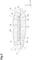
- FIG. 3 is a cross-sectional view along line III-III in FIG. 1 .
- the recess 10 is a recessed portion recessed from the lower surface 7e of the leg portion 7A to the positive side in the Z axis direction.
- the recess 10 functions as an uneven structure (concavo-convex structure) for restricting movement of the magnet 3 in the X axis direction and the Y axis direction on the lower surface 7e of the leg portion 7A.
- the uneven structure is a structure provided on a junction surface between the magnet 3 and at least one of the first core 1 and the second core 2.
- the uneven structure is provided on the junction surface (the lower surface 7e of the leg portion 7A) between the first core 1 and the magnet 3.
- the uneven structure is a structure including a recessed structure, a projecting structure, and a structure including both a recessed shape and a projecting shape in a broad sense.
- the recessed structure is constituted by the recess 10.
- the recess 10 has a rectangular shape when viewed in the Z axis direction.
- the depth (dimension in the Z axis direction) of the recess 10 is larger than the thickness of the magnet 3.
- the recess 10 has inner side surfaces 10a, 10b, 10c, and 10d, and a bottom surface 10e.
- the inner side surfaces 10a, 10b, 10c, and 10d are surfaces that rise from four side portions of the bottom surface 10e toward the negative side in the Z axis direction.
- the inner side surface 10a extends in the X axis direction at a position corresponding to the side portion of the bottom surface 10e on the positive side in the Y axis direction.
- the inner side surface 10b extends in the X axis direction at a position corresponding to the side portion of the bottom surface 10e on the negative side in the Y axis direction.
- the inner side surfaces 10a and 10b face each other in a state in which they are separated from each other in the Y axis direction and parallel to the XZ plane.
- the inner side surface 10c extends in the Y axis direction at a position corresponding to the side portion of the bottom surface 10e on the negative side in the X axis direction.
- the inner side surface 10d extends in the Y axis direction at a position corresponding to the side portion of the bottom surface 10e on the positive side in the X axis direction.
- the inner side surfaces 10c and 10d face each other in a state in which they are separated from each other in the X axis direction and parallel to the YZ plane.
- a pair of restriction wall portions 11 and 12 protruding in a manner of facing each other in the X axis direction are formed in the first core 1.
- a pair of restriction wall portions 13 and 14 protruding in a manner of facing each other in the Y axis direction are formed in the first core 1.
- the restriction wall portions 11 and 12 are wall portions respectively having the inner side surfaces 10c and 10d on an inner circumferential side.
- the restriction wall portions 11 and 12 are wall portions protruding from the bottom surface 10e to the negative side in the Z axis direction and extending in the Y axis direction at positions on the side surfaces 7c and 7d of the leg portion 7A.
- the restriction wall portions 11 and 12 extend from the side surface 7a of the leg portion 7A to a position leading to the side surface 7b. That is, the restriction wall portions 11 and 12 are formed throughout the entire region of the leg portion 7A in the Y axis direction.
- the restriction wall portions 13 and 14 are wall portions having the inner side surfaces 10a and 10b on an inner circumferential side.
- the restriction wall portions 13 and 14 are wall portions protruding from the bottom surface 10e to the negative side in the Z axis direction and extending in the X axis direction at positions on the side surfaces 7a and 7b of the leg portion 7A.
- the restriction wall portions 13 and 14 extend from the side surface 7c of the leg portion 7A to a position leading to the side surface 7d. That is, the restriction wall portions 13 and 14 are formed throughout the entire region of the leg portion 7A in the X axis direction.
- end portions of the restriction wall portions 13 and 14 on both sides are joined to the restriction wall portions 11 and 12.
- the recess 10 is surrounded by the inner side surfaces 10a, 10b, 10c, and 10d throughout the circumference with no gap therebetween.
- the restriction wall portions 11, 12, 13, and 14 are not each required to extend in the entire regions in the longitudinal direction and may be partially cut out.
- the magnet 3 is disposed inside the internal space (refer to FIG. 3 ). In the internal space, the magnet 3 is in a state in which the upper surface 3a and the bottom surface 10e of the recess 10 face each other in the Z axis direction and the lower surface 3b and the upper surface 2a of the second core 2 face each other in the Z axis direction. In the present embodiment, the upper surface 3a of the magnet 3 comes into contact with the bottom surface 10e of the recess 10.
- the lower surface 3b of the magnet 3 comes into contact with a gap sheet 16 disposed on the upper surface 2a. Accordingly, the magnet 3 is sandwiched between the first core 1 and the second core 2.
- the positional relationships between the magnet 3 and the bottom surface 10e and between the magnet 3 and the upper surface 2a are not particularly limited. The magnet 3 need only be sandwiched between the first core 1 and the second core 2.
- the magnet 3 is disposed in a state in which movement thereof in the X axis direction is restricted by the restriction wall portions 11 and 12.
- the magnet 3 is disposed in a state in which movement thereof in the Y axis direction is restricted by the restriction wall portions 13 and 14.
- the magnet 3 is disposed such that a side surface 3f faces the inner side surface 10c of the restriction wall portion 11 in the X axis direction and the side surface 3e faces the inner side surface 10d of the restriction wall portion 12 in the X axis direction.
- the magnet 3 is disposed such that the side surface 3c faces the inner side surface 10a of the restriction wall portion 13 in the Y axis direction and the side surface 3d faces the inner side surface 10b of the restriction wall portion 14 in the Y axis direction.
- a gap may be formed between each of the side surfaces of the magnet 3 and one of the restriction wall portions. However, when movement of the magnet 3 is restricted, each of the side surfaces of the magnet 3 abuts one of the restriction wall portions.
- a shape corresponding to the recess 10 is formed in a die used for molding the first core 1.
- the magnet 3 is disposed between the leg portion 7A on one side of the first core 1 and the second core 2. Accordingly, DC superimposition characteristics of the coil component 100 are enhanced.
- movement of the magnet 3 in the X axis direction and the Y axis direction intersecting orthogonal to the Z axis direction which is the opposite direction in which the first core 1 and the second core 2 face each other is restricted due to the recessed structure of the recess 10. Therefore, even when the coil component 100 vibrates, movement of the magnet 3 in the X axis direction and the Y axis direction is restricted by the recessed structure of the recess 10. Accordingly, positional dislocation of the magnet 3 with respect to the cores 1 and 2 can be curbed.
- positioning and mounting of the magnet 3 are facilitated. Therefore, mass production efficiency of the coil component 100 can be improved.
- the pair of restriction wall portions 11 and 12 protruding in a manner of facing each other in the X axis direction are formed in the first core 1, and movement of the magnet 3 in the X axis direction is restricted by the restriction wall portions 11 and 12. Accordingly, movement of the magnet 3 in the X axis direction can be restricted by a simple structure of the pair of restriction wall portions 11 and 12.
- the pair of restriction wall portions 13 and 14 protruding in a manner of facing each other in the Y axis direction are formed in the first core 1, and movement of the magnet 3 in the Y axis direction is restricted by the restriction wall portions 13 and 14. Accordingly, in addition to movement of the magnet 3 in the X axis direction, movement of the magnet 3 in the Y axis direction can also be restricted.
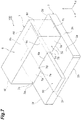
- FIG. 7 is a perspective view illustrating a disposition example when a coil portion 50 is disposed in the coil component 100.
- the first core 1 has the pair of leg portions 7A and 7B.
- the magnet 3 is disposed in at least one of the pair of leg portions 7A and 7B, and the coil portion 50 is disposed between the pair of leg portions 7A and 7B.
- the coil portion is a sheet metal coil, a pattern coil in a substrate (multi-layer substrate), or the like.
- the present invention is not limited to the embodiment described above.
- the coil component 100 illustrated in FIG. 4 may be employed.
- a recess 20 formed in the leg portion 7A has a structure different from that of the recess 10 illustrated in FIG. 2 .
- the recess 20 has the inner side surfaces 10c and 10d and the bottom surface 10e but is constituted to penetrate the leg portion 7A in the Y axis direction.
- the recess 20 opens to the positive side in the Y axis direction on the side surface 7a and opens to the negative side in the Y axis direction on the side surface 7b. That is, in the structure illustrated in FIG.
- the first core 1 has the restriction wall portions 11 and 12 facing each other in the X axis direction but does not have the restriction wall portions 13 and 14 (refer to FIG. 2 ) facing each other in the Y axis direction.
- the restriction wall portions 11 and 12 may be disposed to face each other in a vibration direction of the coil component 100 the vibration direction being found in advance.
- the recess 20 is formed, similar to the recess 10, a corresponding shape may be provided in a die, or the recess 20 can be formed through cutting. That is, the recess 20 may be formed by cutting the flat surface-shaped lower surface 7e of the leg portion 7A. This is because a cutting tool can pass therethrough since the recess 20 penetrates the leg portion 7A in the Y axis direction.
- the recess 10 or 20 is formed only in the leg portion 7A. However, when the magnet 3 is also disposed on the leg portion 7B side, the recess 10 or 20 may also be formed in the leg portion 7B. In addition, the recess 20 penetrates the leg portion 7A in the Y axis direction but may penetrate the leg portion 7A in the X axis direction. When the recess 20 is formed in both the leg portion 7A and the leg portion 7B, if a constitution in which the recess 20 penetrates both the leg portion 7A and the leg portion 7B in the X axis direction is adopted, the recess 20 can be formed in the leg portion 7A and the leg portion 7B at the same time using a cutting tool. The recess 10 or 20 may be formed only in the leg portion 7B.
- protruding portions 31 and 32 protruding toward the first core 1 are formed in the magnet 3.
- the protruding portion 31 protrudes from the side surface 3f toward the negative side in the X axis direction.
- the protruding portion 31 is inserted into a recessed portion 11a formed on the inner side surface 10c of the restriction wall portion 11.
- the protruding portion 32 protrudes from the side surface 3e toward the positive side in the X axis direction.
- the protruding portion 32 is inserted into a recessed portion 12a formed on the inner side surface 10d of the restriction wall portion 12. Accordingly, movement of the magnet 3 in the Y axis direction can be restricted due to the protruding portions 31 and 32 of the magnet 3 which are fitted into the recessed portions 11a and 12a of the first core 1.
- an uneven structure for restricting movement of the magnet 3 in a direction along the XY plane may be formed in any way with respect to any constituent element of the first core 1, the second core 2, and the magnet 3.
- the constitution illustrated in FIG. 6A, 6B and 6C may be employed.
- a protruding portion 36 protruding to the positive side in the Z axis direction is formed in the magnet 3.
- the protruding portion 36 is inserted into a recess 37 of the leg portion 7A of the first core 1. Accordingly, movement of the magnet 3 in the X axis direction and the Y axis direction is restricted by the recess 37 of the leg portion 7A via the protruding portion 36.
- an uneven structure for restricting movement of the magnet 3 in at least one of the X axis direction and the Y axis direction is constituted by combining the protruding portion 36 and the recess 37.
- a recess 38 recessed to the negative side in the Z axis direction is formed in the magnet 3.
- a protruding portion 39 of the first core 1 is inserted into the recess 38. Accordingly, movement of the magnet 3 in a direction along the XY plane is restricted by the protruding portion 39 of the leg portion 7A via the recess 38. In this manner, an uneven structure for restricting movement of the magnet 3 in at least one of the X axis direction and the Y axis direction is constituted by combining the protruding portion 39 and the recess 38.
- a recess 41 is formed in the second core 2, and the recess 41 is inserted into the magnet 3. Accordingly, movement of the magnet 3 in a direction along the XY plane is restricted by the recess 41. In this manner, an uneven structure for restricting movement of the magnet 3 in at least one of the X axis direction and the Y axis direction is constituted by the recess 41.
Landscapes
- Engineering & Computer Science (AREA)
- Power Engineering (AREA)
- Chemical & Material Sciences (AREA)
- Composite Materials (AREA)
- Coils Or Transformers For Communication (AREA)
- Coils Of Transformers For General Uses (AREA)
Abstract
Description
- The present invention relates to a coil component.
- In the related art, a coil component disclosed in Japanese Unexamined Patent Publication No.
S50-133453 - Here, when a coil component vibrates, a magnet may be positionally dislocated. When a magnet is positionally dislocated in this manner, there is a problem of deterioration in DC superimposition characteristics of the coil component.
- An object of the present invention is to provide a coil component in which positional dislocation of a magnet with respect to a core can be curbed.
- According to the present invention, there is provided a coil component including a first core having a leg portion, a second core joined to the first core with the leg portion therebetween, and a magnet disposed between the leg portion and the second core. Movement of the magnet in a first direction intersecting an opposite direction in which the first core and the second core face each other is at least restricted by an uneven structure provided on a junction surface between the magnet and at least one of the first core and the second core.
- In the coil component according to the present invention, the magnet is disposed between the leg portion of the first core and the second core. Accordingly, DC superimposition characteristics of the coil component are enhanced. Here, movement of the magnet in the first direction intersecting the opposite direction in which the first core and the second core face each other is at least restricted by the uneven structure. Therefore, even when the coil component vibrates, movement of the magnet at least in the first direction is restricted by the uneven structure. Accordingly, positional dislocation of the magnet with respect to the core can be curbed.
- A pair of first restriction wall portions protruding in a manner of facing each other in the first direction are formed in at least one of the first core and the second core. Movement of the magnet in the first direction may be restricted by the first restriction wall portions. Accordingly, movement of the magnet in the first direction can be restricted by a simple structure of the pair of first restriction wall portions.
- A pair of second restriction wall portions protruding in a manner of facing each other in a second direction intersecting the opposite direction and the first direction may be formed in at least one of the first core and the second core. Movement of the magnet in the second direction may be restricted by the second restriction wall portions. Accordingly, in addition to movement of the magnet in the first direction, movement of the magnet in the second direction can also be restricted.
- A protruding portion protruding toward at least one of the first core and the second core may be formed in the magnet. Accordingly, the protruding portion of the magnet is fitted to at least one of the first core and the second core, and thus movement of the magnet can be restricted.
- The first core may have the pair of leg portions, and the magnet may be disposed in at least one of the pair of leg portions. A coil portion may be disposed between the pair of leg portions.
- According to the present invention, it is possible to provide a coil component in which positional dislocation of a magnet with respect to a core can be curbed.
-
-
FIG. 1 is a plan view illustrating a coil component according to an embodiment of the present invention. -
FIG. 2 is a development view of the coil component. -
FIG. 3 is a cross-sectional view along line III-III inFIG. 1 . -
FIG. 4 is a development view of the coil component according to a modification example. -
FIG. 5 is an enlarged view of a leg portion and a magnet of the coil component according to the modification example. -
FIGS. 6A, 6B, and 6C are cross-sectional views of the coil component according to the modification example. -
FIG. 7 is a view illustrating the coil component in which a coil portion is illustrated. - With reference to
FIG. 1 , a coil component according to an embodiment of the present invention will be described.FIG. 1 is a plan view illustrating acoil component 100 according to the embodiment of the present invention.FIG. 2 is a development view of thecoil component 100. - As illustrated in
FIGS. 1 and2 , thecoil component 100 includes afirst core 1, asecond core 2, and a magnet 3 (refer toFIG. 2 ). An opposite direction in which thefirst core 1 and thesecond core 2 face each other will be referred to as a Z axis direction. Thefirst core 1 side will be referred to as a positive side in the Z axis direction. A direction perpendicular to the Z axis direction will be referred to as an X axis direction, and a direction perpendicular to the Z axis direction and the X axis direction will be referred to as a Y axis direction. In the present embodiment, the X axis direction corresponds to "a first direction" in the claims, and the Y axis direction corresponds to "a second direction" in the claims. However, the directions are not limited to the foregoing correspondence relationship. When the Y axis direction is considered to correspond to "the first direction", the X axis direction corresponds to "the second direction". - The
first core 1 is a U-shaped core. Thefirst core 1 includes amain body portion 6 and a pair ofleg portions main body portion 6 forms a rectangular parallelepiped of which a longitudinal direction lies in the X axis direction. Themain body portion 6 has alower surface 6a, anupper surface 6b,side surfaces end surfaces lower surface 6a expands parallel to an XY plane at a position on a negative side in the Z axis direction. Theupper surface 6b expands parallel to the XY plane at a position on the positive side in the Z axis direction. Theside surfaces end surfaces - The
leg portions lower surface 6a of themain body portion 6 toward the negative side in the Z axis direction. Theleg portion 7A is provided at an end portion of themain body portion 6 on the negative side in the X axis direction. Theleg portion 7B is provided at another end portion of themain body portion 6 on the positive side in the X axis direction. Theleg portion 7A and theleg portion 7B are separated from each other in the X axis direction. - The
leg portions leg portions side surfaces lower surface 7e. Theside surfaces side surfaces main body portion 6 and indicates the side of theend surfaces lower surface 7e expands parallel to the XY plane at a position on the negative side in the Z axis direction. A recess 10 (refer toFIG. 2 ) is formed on thelower surface 7e of theleg portion 7A. A detailed constitution of therecess 10 will be described below. In the present embodiment, the side surfaces 7a and 7b of theleg portions main body portion 6. Theside surface 7c of theleg portion 7A is flush with theend surface 6e of themain body portion 6. Theside surface 7c of theleg portion 7B is flush with theend surface 6f of themain body portion 6. However, the shapes of theleg portions main body portion 6, and the like are not particularly limited. - The
second core 2 is an I-shaped core. Thesecond core 2 is joined to thefirst core 1 with theleg portions second core 2 has a rectangular plate shape expanding parallel to the XY plane. Thesecond core 2 has anupper surface 2a, alower surface 2b, andside surfaces upper surface 2a expands parallel to the XY plane at a position on the positive side in the Z axis direction. Thelower surface 2b expands parallel to the XY plane at a position on the negative side in the Z axis direction. The side surfaces 2c and 2d individually expand parallel to the XZ plane at positions on the positive side and the negative side in the Y axis direction. The side surfaces 2e and 2f expand parallel to the YZ plane at positions on the positive side and the negative side in the X axis direction. - The
first core 1 is connected to theupper surface 2a of thesecond core 2. The lower surfaces 7e of theleg portions first core 1 are disposed such that they are close to or in contact with theupper surface 2a of thesecond core 2 and parallel thereto. In the present embodiment, thefirst core 1 is disposed in a region on the negative side in the Y axis direction on theupper surface 2a of thesecond core 2. - As illustrated in
FIG. 2 , themagnet 3 is disposed between theleg portion 7A and thesecond core 2. Themagnet 3 is a rectangular-plate-shaped permanent magnet expanding parallel to the XY plane. Themagnet 3 has anupper surface 3a, alower surface 3b, andside surfaces upper surface 2a expands parallel to the XY plane at a position on the positive side in the Z axis direction. Thelower surface 3b expands parallel to the XY plane at a position on the negative side in the Z axis direction. The side surfaces 3c and 3d individually expand parallel to the XZ plane at positions on the positive side and the negative side in the Y axis direction. The side surfaces 3e and 3f expand parallel to the YZ plane at positions on the positive side and the negative side in the X axis direction. Themagnet 3 is disposed inside therecess 10 formed on thelower surface 7e of theleg portion 7A. Accordingly, themagnet 3 is disposed inside a region surrounded by the side surfaces 7a, 7b, 7c, and 7d of theleg portion 7A when viewed in the Z axis direction. - Next, with reference to
FIGS. 2 and3 , a constitution in the vicinity of therecess 10 of theleg portion 7A will be described.FIG. 3 is a cross-sectional view along line III-III inFIG. 1 . Therecess 10 is a recessed portion recessed from thelower surface 7e of theleg portion 7A to the positive side in the Z axis direction. Therecess 10 functions as an uneven structure (concavo-convex structure) for restricting movement of themagnet 3 in the X axis direction and the Y axis direction on thelower surface 7e of theleg portion 7A. The uneven structure is a structure provided on a junction surface between themagnet 3 and at least one of thefirst core 1 and thesecond core 2. In the present embodiment, the uneven structure is provided on the junction surface (thelower surface 7e of theleg portion 7A) between thefirst core 1 and themagnet 3. The uneven structure is a structure including a recessed structure, a projecting structure, and a structure including both a recessed shape and a projecting shape in a broad sense. In the present embodiment, the recessed structure is constituted by therecess 10. Therecess 10 has a rectangular shape when viewed in the Z axis direction. The depth (dimension in the Z axis direction) of therecess 10 is larger than the thickness of themagnet 3. Therecess 10 hasinner side surfaces bottom surface 10e. - The
inner side surfaces bottom surface 10e toward the negative side in the Z axis direction. Theinner side surface 10a extends in the X axis direction at a position corresponding to the side portion of thebottom surface 10e on the positive side in the Y axis direction. The inner side surface 10b extends in the X axis direction at a position corresponding to the side portion of thebottom surface 10e on the negative side in the Y axis direction. The inner side surfaces 10a and 10b face each other in a state in which they are separated from each other in the Y axis direction and parallel to the XZ plane. Theinner side surface 10c extends in the Y axis direction at a position corresponding to the side portion of thebottom surface 10e on the negative side in the X axis direction. Theinner side surface 10d extends in the Y axis direction at a position corresponding to the side portion of thebottom surface 10e on the positive side in the X axis direction. The inner side surfaces 10c and 10d face each other in a state in which they are separated from each other in the X axis direction and parallel to the YZ plane. - Since the
recess 10 is formed as described above, a pair ofrestriction wall portions 11 and 12 (first restriction wall portions) protruding in a manner of facing each other in the X axis direction are formed in thefirst core 1. In addition, a pair ofrestriction wall portions 13 and 14 (second restriction wall portions) protruding in a manner of facing each other in the Y axis direction are formed in thefirst core 1. - The
restriction wall portions restriction wall portions bottom surface 10e to the negative side in the Z axis direction and extending in the Y axis direction at positions on the side surfaces 7c and 7d of theleg portion 7A. Therestriction wall portions side surface 7a of theleg portion 7A to a position leading to theside surface 7b. That is, therestriction wall portions leg portion 7A in the Y axis direction. - The
restriction wall portions restriction wall portions bottom surface 10e to the negative side in the Z axis direction and extending in the X axis direction at positions on the side surfaces 7a and 7b of theleg portion 7A. Therestriction wall portions side surface 7c of theleg portion 7A to a position leading to theside surface 7d. That is, therestriction wall portions leg portion 7A in the X axis direction. In addition, end portions of therestriction wall portions restriction wall portions recess 10 is surrounded by theinner side surfaces restriction wall portions - When the
lower surface 7e of theleg portion 7A of thefirst core 1 is disposed on theupper surface 2a of thesecond core 2, an opening portion of therecess 10 is blocked by theupper surface 2a. Accordingly, an internal space is formed by therecess 10 between thefirst core 1 and thesecond core 2. Themagnet 3 is disposed inside the internal space (refer toFIG. 3 ). In the internal space, themagnet 3 is in a state in which theupper surface 3a and thebottom surface 10e of therecess 10 face each other in the Z axis direction and thelower surface 3b and theupper surface 2a of thesecond core 2 face each other in the Z axis direction. In the present embodiment, theupper surface 3a of themagnet 3 comes into contact with thebottom surface 10e of therecess 10. In addition, thelower surface 3b of themagnet 3 comes into contact with agap sheet 16 disposed on theupper surface 2a. Accordingly, themagnet 3 is sandwiched between thefirst core 1 and thesecond core 2. However, the positional relationships between themagnet 3 and thebottom surface 10e and between themagnet 3 and theupper surface 2a are not particularly limited. Themagnet 3 need only be sandwiched between thefirst core 1 and thesecond core 2. - In addition, in the internal space formed by the
recess 10, themagnet 3 is disposed in a state in which movement thereof in the X axis direction is restricted by therestriction wall portions magnet 3 is disposed in a state in which movement thereof in the Y axis direction is restricted by therestriction wall portions magnet 3 is disposed such that aside surface 3f faces theinner side surface 10c of therestriction wall portion 11 in the X axis direction and theside surface 3e faces theinner side surface 10d of therestriction wall portion 12 in the X axis direction. In addition, themagnet 3 is disposed such that theside surface 3c faces theinner side surface 10a of therestriction wall portion 13 in the Y axis direction and theside surface 3d faces the inner side surface 10b of therestriction wall portion 14 in the Y axis direction. A gap may be formed between each of the side surfaces of themagnet 3 and one of the restriction wall portions. However, when movement of themagnet 3 is restricted, each of the side surfaces of themagnet 3 abuts one of the restriction wall portions. - When the
recess 10 is formed as described above, a shape corresponding to therecess 10 is formed in a die used for molding thefirst core 1. - Next, operation and effects of the
coil component 100 according to the present embodiment will be described. - In the
coil component 100 according to the present embodiment, themagnet 3 is disposed between theleg portion 7A on one side of thefirst core 1 and thesecond core 2. Accordingly, DC superimposition characteristics of thecoil component 100 are enhanced. Here, movement of themagnet 3 in the X axis direction and the Y axis direction intersecting orthogonal to the Z axis direction which is the opposite direction in which thefirst core 1 and thesecond core 2 face each other is restricted due to the recessed structure of therecess 10. Therefore, even when thecoil component 100 vibrates, movement of themagnet 3 in the X axis direction and the Y axis direction is restricted by the recessed structure of therecess 10. Accordingly, positional dislocation of themagnet 3 with respect to thecores magnet 3 into therecess 10, positioning and mounting of themagnet 3 are facilitated. Therefore, mass production efficiency of thecoil component 100 can be improved. - The pair of
restriction wall portions first core 1, and movement of themagnet 3 in the X axis direction is restricted by therestriction wall portions magnet 3 in the X axis direction can be restricted by a simple structure of the pair ofrestriction wall portions - The pair of
restriction wall portions first core 1, and movement of themagnet 3 in the Y axis direction is restricted by therestriction wall portions magnet 3 in the X axis direction, movement of themagnet 3 in the Y axis direction can also be restricted. - Here,
FIG. 7 is a perspective view illustrating a disposition example when acoil portion 50 is disposed in thecoil component 100. As illustrated inFIG. 7 , thefirst core 1 has the pair ofleg portions magnet 3 is disposed in at least one of the pair ofleg portions coil portion 50 is disposed between the pair ofleg portions - The present invention is not limited to the embodiment described above.
- For example, the
coil component 100 illustrated inFIG. 4 may be employed. In thecoil component 100, arecess 20 formed in theleg portion 7A has a structure different from that of therecess 10 illustrated inFIG. 2 . Therecess 20 has the inner side surfaces 10c and 10d and thebottom surface 10e but is constituted to penetrate theleg portion 7A in the Y axis direction. Therecess 20 opens to the positive side in the Y axis direction on theside surface 7a and opens to the negative side in the Y axis direction on theside surface 7b. That is, in the structure illustrated inFIG. 4 , thefirst core 1 has therestriction wall portions restriction wall portions 13 and 14 (refer toFIG. 2 ) facing each other in the Y axis direction. In this case, movement of themagnet 3 in the X axis direction is restricted by therestriction wall portions magnet 3 in the Y axis direction is not restricted. When the structure is employed, therestriction wall portions coil component 100 the vibration direction being found in advance. When therecess 20 is formed, similar to therecess 10, a corresponding shape may be provided in a die, or therecess 20 can be formed through cutting. That is, therecess 20 may be formed by cutting the flat surface-shapedlower surface 7e of theleg portion 7A. This is because a cutting tool can pass therethrough since therecess 20 penetrates theleg portion 7A in the Y axis direction. - The
recess leg portion 7A. However, when themagnet 3 is also disposed on theleg portion 7B side, therecess leg portion 7B. In addition, therecess 20 penetrates theleg portion 7A in the Y axis direction but may penetrate theleg portion 7A in the X axis direction. When therecess 20 is formed in both theleg portion 7A and theleg portion 7B, if a constitution in which therecess 20 penetrates both theleg portion 7A and theleg portion 7B in the X axis direction is adopted, therecess 20 can be formed in theleg portion 7A and theleg portion 7B at the same time using a cutting tool. Therecess leg portion 7B. - In addition, the constitution illustrated in
FIG. 5 may be employed. In the constitution illustrated inFIG. 5 , protrudingportions first core 1 are formed in themagnet 3. The protrudingportion 31 protrudes from theside surface 3f toward the negative side in the X axis direction. The protrudingportion 31 is inserted into a recessedportion 11a formed on theinner side surface 10c of therestriction wall portion 11. The protrudingportion 32 protrudes from theside surface 3e toward the positive side in the X axis direction. The protrudingportion 32 is inserted into a recessedportion 12a formed on theinner side surface 10d of therestriction wall portion 12. Accordingly, movement of themagnet 3 in the Y axis direction can be restricted due to the protrudingportions magnet 3 which are fitted into the recessedportions first core 1. - In addition, an uneven structure for restricting movement of the
magnet 3 in a direction along the XY plane may be formed in any way with respect to any constituent element of thefirst core 1, thesecond core 2, and themagnet 3. For example, the constitution illustrated inFIG. 6A, 6B and 6C may be employed. In the constitution illustrated inFIG. 6A , a protrudingportion 36 protruding to the positive side in the Z axis direction is formed in themagnet 3. In addition, the protrudingportion 36 is inserted into arecess 37 of theleg portion 7A of thefirst core 1. Accordingly, movement of themagnet 3 in the X axis direction and the Y axis direction is restricted by therecess 37 of theleg portion 7A via the protrudingportion 36. In this manner, an uneven structure for restricting movement of themagnet 3 in at least one of the X axis direction and the Y axis direction is constituted by combining the protrudingportion 36 and therecess 37. - In addition, in the constitution illustrated in
FIG. 6B , arecess 38 recessed to the negative side in the Z axis direction is formed in themagnet 3. In addition, a protrudingportion 39 of thefirst core 1 is inserted into therecess 38. Accordingly, movement of themagnet 3 in a direction along the XY plane is restricted by the protrudingportion 39 of theleg portion 7A via therecess 38. In this manner, an uneven structure for restricting movement of themagnet 3 in at least one of the X axis direction and the Y axis direction is constituted by combining the protrudingportion 39 and therecess 38. - In addition, in the constitution illustrated in
FIG. 6C , arecess 41 is formed in thesecond core 2, and therecess 41 is inserted into themagnet 3. Accordingly, movement of themagnet 3 in a direction along the XY plane is restricted by therecess 41. In this manner, an uneven structure for restricting movement of themagnet 3 in at least one of the X axis direction and the Y axis direction is constituted by therecess 41. -
- 1
- First core
- 2
- Second core
- 3
- Magnet
- 7A, 7B
- Leg portion
- 10, 20, 38, 41
- Recess (uneven structure)
- 11, 12
- Restriction wall (first restriction wall)
- 13, 14
- Restriction wall (second restriction wall)
- 31, 32, 36, 39
- Protruding portion
- 100
- Coil component
Claims (5)
- A coil component comprising:a first core having a leg portion;a second core joined to the first core with the leg portion therebetween; anda magnet disposed between the leg portion and the second core,wherein movement of the magnet in a first direction intersecting an opposite direction in which the first core and the second core face each other is at least restricted by an uneven structure provided on a junction surface between the magnet and at least one of the first core and the second core.
- The coil component according to claim 1,wherein a pair of first restriction wall portions protruding in a manner of facing each other in the first direction are formed in at least one of the first core and the second core, andwherein movement of the magnet in the first direction is restricted by the first restriction wall portions.
- The coil component according to claim 2,wherein a pair of second restriction wall portions protruding in a manner of facing each other in a second direction intersecting the opposite direction and the first direction are formed in at least one of the first core and the second core, andwherein movement of the magnet in the second direction is restricted by the second restriction wall portions.
- The coil component according to any one of claims 1 to 3,
wherein a protruding portion protruding toward at least one of the first core and the second core is formed in the magnet. - The coil component according to any one of claims 1 to 4,wherein the first core has the pair of leg portions, and the magnet is disposed in at least one of the pair of leg portions, andwherein a coil portion is disposed between the pair of leg portions.
Applications Claiming Priority (1)
| Application Number | Priority Date | Filing Date | Title |
|---|---|---|---|
| JP2019232039A JP7425962B2 (en) | 2019-12-23 | 2019-12-23 | coil parts |
Publications (2)
| Publication Number | Publication Date |
|---|---|
| EP3843112A1 true EP3843112A1 (en) | 2021-06-30 |
| EP3843112B1 EP3843112B1 (en) | 2024-01-03 |
Family
ID=73856866
Family Applications (1)
| Application Number | Title | Priority Date | Filing Date |
|---|---|---|---|
| EP20216592.4A Active EP3843112B1 (en) | 2019-12-23 | 2020-12-22 | Coil component |
Country Status (4)
| Country | Link |
|---|---|
| US (1) | US11615909B2 (en) |
| EP (1) | EP3843112B1 (en) |
| JP (1) | JP7425962B2 (en) |
| CN (1) | CN113096935A (en) |
Families Citing this family (1)
| Publication number | Priority date | Publication date | Assignee | Title |
|---|---|---|---|---|
| TWI875102B (en) * | 2023-07-27 | 2025-03-01 | 新聿科技股份有限公司 | Combination inductor to enhance the heat dissipation effect of liquid cooling or air cooling |
Citations (5)
| Publication number | Priority date | Publication date | Assignee | Title |
|---|---|---|---|---|
| JPS50133453A (en) | 1974-04-10 | 1975-10-22 | ||
| US4103221A (en) * | 1973-05-18 | 1978-07-25 | Hitachi Metals, Ltd. | Inductor with plurality of magnet pieces in air gap |
| DE3202600A1 (en) * | 1981-01-27 | 1982-09-09 | Zumtobel AG, 6850 Dornbirn | Inductive voltage or current limiter |
| JPH07176431A (en) * | 1993-12-16 | 1995-07-14 | Tabuchi Denki Kk | Induction electromagnetic device |
| FR2839580A1 (en) * | 2002-05-10 | 2003-11-14 | Johnson Contr Automotive Elect | MAGNETIC SHORT-CIRCUIT PERMANENT MAGNET IGNITION COIL |
Family Cites Families (11)
| Publication number | Priority date | Publication date | Assignee | Title |
|---|---|---|---|---|
| US3968465A (en) * | 1973-05-18 | 1976-07-06 | Hitachi Metals, Ltd. | Inductor and method for producing same |
| JPS558888Y2 (en) * | 1974-02-22 | 1980-02-27 | ||
| JPH0539688A (en) * | 1991-10-02 | 1993-02-19 | Taamo:Kk | Attracting tool |
| US6717504B2 (en) * | 2000-10-25 | 2004-04-06 | Nec Tokin Corporation | Magnetic core including bias magnet and inductor component using the same |
| JP3797660B2 (en) * | 2001-11-19 | 2006-07-19 | Necトーキン株式会社 | Inductance parts |
| JP3922121B2 (en) * | 2002-07-18 | 2007-05-30 | 三菱電機株式会社 | DC reactor |
| DE10259117A1 (en) * | 2002-12-18 | 2004-07-01 | Technische Universität Ilmenau Abteilung Forschungsförderung und Technologietransfer | Inductive component to be magnetically compensated in ferromagnetic circuit has coil and magnetic circuit made from ferromagnetic material |
| GB2451447B (en) | 2007-07-30 | 2012-01-11 | Sensl Technologies Ltd | Light sensor |
| ATE531055T1 (en) * | 2009-02-05 | 2011-11-15 | Abb Oy | PERMANENT MAGNET DC CHOKER COIL |
| US8416045B2 (en) * | 2011-06-27 | 2013-04-09 | Onyxip, Inc. | Magnetic power converter |
| JP5857524B2 (en) * | 2011-08-18 | 2016-02-10 | Fdk株式会社 | choke coil |
-
2019
- 2019-12-23 JP JP2019232039A patent/JP7425962B2/en active Active
-
2020
- 2020-12-21 US US17/128,387 patent/US11615909B2/en active Active
- 2020-12-22 CN CN202011525803.0A patent/CN113096935A/en active Pending
- 2020-12-22 EP EP20216592.4A patent/EP3843112B1/en active Active
Patent Citations (5)
| Publication number | Priority date | Publication date | Assignee | Title |
|---|---|---|---|---|
| US4103221A (en) * | 1973-05-18 | 1978-07-25 | Hitachi Metals, Ltd. | Inductor with plurality of magnet pieces in air gap |
| JPS50133453A (en) | 1974-04-10 | 1975-10-22 | ||
| DE3202600A1 (en) * | 1981-01-27 | 1982-09-09 | Zumtobel AG, 6850 Dornbirn | Inductive voltage or current limiter |
| JPH07176431A (en) * | 1993-12-16 | 1995-07-14 | Tabuchi Denki Kk | Induction electromagnetic device |
| FR2839580A1 (en) * | 2002-05-10 | 2003-11-14 | Johnson Contr Automotive Elect | MAGNETIC SHORT-CIRCUIT PERMANENT MAGNET IGNITION COIL |
Also Published As
| Publication number | Publication date |
|---|---|
| JP2021100080A (en) | 2021-07-01 |
| US20210193363A1 (en) | 2021-06-24 |
| EP3843112B1 (en) | 2024-01-03 |
| US11615909B2 (en) | 2023-03-28 |
| CN113096935A (en) | 2021-07-09 |
| JP7425962B2 (en) | 2024-02-01 |
Similar Documents
| Publication | Publication Date | Title |
|---|---|---|
| JP4946559B2 (en) | Electromagnetic relay | |
| JP6536284B2 (en) | Ignition coil for internal combustion engine | |
| US9692281B2 (en) | Method for producing rotor laminated core | |
| CN101271799B (en) | Electromagnetic relay | |
| JPWO2015008544A1 (en) | Stator | |
| JPH09328134A (en) | Parts transfer tray | |
| CN107039769B (en) | Antenna device and method of manufacturing the same | |
| US11615909B2 (en) | Coil component | |
| JP5948559B2 (en) | Surface mount electronic components | |
| JP2001339881A (en) | Stator of rotating electric machine and method of manufacturing the same | |
| CN107039801A8 (en) | Board connector | |
| US20230420205A1 (en) | Relay | |
| JP6748886B2 (en) | Electromagnetic relay | |
| JP6277910B2 (en) | Vehicle assembly structure and vehicle assembly part manufacturing method | |
| JP3826464B2 (en) | Electromagnetic relay | |
| JP3771713B2 (en) | Laminated iron core | |
| US20250253080A1 (en) | Core support structure | |
| JP6163085B2 (en) | Pallet for parts alignment and manufacturing method thereof | |
| JP7703775B2 (en) | Fixed structure and electronic unit | |
| JPH0856090A (en) | Cover case mount structure | |
| JP3797660B2 (en) | Inductance parts | |
| JP3084732U (en) | Flyback transformer | |
| CN106787272A (en) | The processing method of stator punching and stator punching | |
| JP2025101925A (en) | connector | |
| CN119789348A (en) | Shell, preparation method thereof and electronic equipment |
Legal Events
| Date | Code | Title | Description |
|---|---|---|---|
| PUAI | Public reference made under article 153(3) epc to a published international application that has entered the european phase |
Free format text: ORIGINAL CODE: 0009012 |
|
| STAA | Information on the status of an ep patent application or granted ep patent |
Free format text: STATUS: THE APPLICATION HAS BEEN PUBLISHED |
|
| AK | Designated contracting states |
Kind code of ref document: A1 Designated state(s): AL AT BE BG CH CY CZ DE DK EE ES FI FR GB GR HR HU IE IS IT LI LT LU LV MC MK MT NL NO PL PT RO RS SE SI SK SM TR |
|
| STAA | Information on the status of an ep patent application or granted ep patent |
Free format text: STATUS: REQUEST FOR EXAMINATION WAS MADE |
|
| 17P | Request for examination filed |
Effective date: 20211228 |
|
| RBV | Designated contracting states (corrected) |
Designated state(s): AL AT BE BG CH CY CZ DE DK EE ES FI FR GB GR HR HU IE IS IT LI LT LU LV MC MK MT NL NO PL PT RO RS SE SI SK SM TR |
|
| GRAP | Despatch of communication of intention to grant a patent |
Free format text: ORIGINAL CODE: EPIDOSNIGR1 |
|
| STAA | Information on the status of an ep patent application or granted ep patent |
Free format text: STATUS: GRANT OF PATENT IS INTENDED |
|
| INTG | Intention to grant announced |
Effective date: 20230405 |
|
| GRAJ | Information related to disapproval of communication of intention to grant by the applicant or resumption of examination proceedings by the epo deleted |
Free format text: ORIGINAL CODE: EPIDOSDIGR1 |
|
| STAA | Information on the status of an ep patent application or granted ep patent |
Free format text: STATUS: REQUEST FOR EXAMINATION WAS MADE |
|
| GRAP | Despatch of communication of intention to grant a patent |
Free format text: ORIGINAL CODE: EPIDOSNIGR1 |
|
| STAA | Information on the status of an ep patent application or granted ep patent |
Free format text: STATUS: GRANT OF PATENT IS INTENDED |
|
| INTC | Intention to grant announced (deleted) | ||
| INTG | Intention to grant announced |
Effective date: 20230810 |
|
| GRAS | Grant fee paid |
Free format text: ORIGINAL CODE: EPIDOSNIGR3 |
|
| GRAA | (expected) grant |
Free format text: ORIGINAL CODE: 0009210 |
|
| STAA | Information on the status of an ep patent application or granted ep patent |
Free format text: STATUS: THE PATENT HAS BEEN GRANTED |
|
| AK | Designated contracting states |
Kind code of ref document: B1 Designated state(s): AL AT BE BG CH CY CZ DE DK EE ES FI FR GB GR HR HU IE IS IT LI LT LU LV MC MK MT NL NO PL PT RO RS SE SI SK SM TR |
|
| REG | Reference to a national code |
Ref country code: GB Ref legal event code: FG4D |
|
| REG | Reference to a national code |
Ref country code: CH Ref legal event code: EP |
|
| REG | Reference to a national code |
Ref country code: DE Ref legal event code: R096 Ref document number: 602020023780 Country of ref document: DE |
|
| REG | Reference to a national code |
Ref country code: IE Ref legal event code: FG4D |
|
| REG | Reference to a national code |
Ref country code: LT Ref legal event code: MG9D |
|
| PG25 | Lapsed in a contracting state [announced via postgrant information from national office to epo] |
Ref country code: ES Free format text: LAPSE BECAUSE OF FAILURE TO SUBMIT A TRANSLATION OF THE DESCRIPTION OR TO PAY THE FEE WITHIN THE PRESCRIBED TIME-LIMIT Effective date: 20240103 |
|
| PG25 | Lapsed in a contracting state [announced via postgrant information from national office to epo] |
Ref country code: ES Free format text: LAPSE BECAUSE OF FAILURE TO SUBMIT A TRANSLATION OF THE DESCRIPTION OR TO PAY THE FEE WITHIN THE PRESCRIBED TIME-LIMIT Effective date: 20240103 |
|
| REG | Reference to a national code |
Ref country code: NL Ref legal event code: MP Effective date: 20240103 |
|
| REG | Reference to a national code |
Ref country code: AT Ref legal event code: MK05 Ref document number: 1647659 Country of ref document: AT Kind code of ref document: T Effective date: 20240103 |
|
| PG25 | Lapsed in a contracting state [announced via postgrant information from national office to epo] |
Ref country code: NL Free format text: LAPSE BECAUSE OF FAILURE TO SUBMIT A TRANSLATION OF THE DESCRIPTION OR TO PAY THE FEE WITHIN THE PRESCRIBED TIME-LIMIT Effective date: 20240103 |
|
| PG25 | Lapsed in a contracting state [announced via postgrant information from national office to epo] |
Ref country code: NL Free format text: LAPSE BECAUSE OF FAILURE TO SUBMIT A TRANSLATION OF THE DESCRIPTION OR TO PAY THE FEE WITHIN THE PRESCRIBED TIME-LIMIT Effective date: 20240103 |
|
| PG25 | Lapsed in a contracting state [announced via postgrant information from national office to epo] |
Ref country code: IS Free format text: LAPSE BECAUSE OF FAILURE TO SUBMIT A TRANSLATION OF THE DESCRIPTION OR TO PAY THE FEE WITHIN THE PRESCRIBED TIME-LIMIT Effective date: 20240503 |
|
| PG25 | Lapsed in a contracting state [announced via postgrant information from national office to epo] |
Ref country code: LT Free format text: LAPSE BECAUSE OF FAILURE TO SUBMIT A TRANSLATION OF THE DESCRIPTION OR TO PAY THE FEE WITHIN THE PRESCRIBED TIME-LIMIT Effective date: 20240103 |
|
| PG25 | Lapsed in a contracting state [announced via postgrant information from national office to epo] |
Ref country code: GR Free format text: LAPSE BECAUSE OF FAILURE TO SUBMIT A TRANSLATION OF THE DESCRIPTION OR TO PAY THE FEE WITHIN THE PRESCRIBED TIME-LIMIT Effective date: 20240404 |
|
| PG25 | Lapsed in a contracting state [announced via postgrant information from national office to epo] |
Ref country code: HR Free format text: LAPSE BECAUSE OF FAILURE TO SUBMIT A TRANSLATION OF THE DESCRIPTION OR TO PAY THE FEE WITHIN THE PRESCRIBED TIME-LIMIT Effective date: 20240103 Ref country code: RS Free format text: LAPSE BECAUSE OF FAILURE TO SUBMIT A TRANSLATION OF THE DESCRIPTION OR TO PAY THE FEE WITHIN THE PRESCRIBED TIME-LIMIT Effective date: 20240403 |
|
| PG25 | Lapsed in a contracting state [announced via postgrant information from national office to epo] |
Ref country code: AT Free format text: LAPSE BECAUSE OF FAILURE TO SUBMIT A TRANSLATION OF THE DESCRIPTION OR TO PAY THE FEE WITHIN THE PRESCRIBED TIME-LIMIT Effective date: 20240103 Ref country code: CZ Free format text: LAPSE BECAUSE OF FAILURE TO SUBMIT A TRANSLATION OF THE DESCRIPTION OR TO PAY THE FEE WITHIN THE PRESCRIBED TIME-LIMIT Effective date: 20240103 |
|
| PG25 | Lapsed in a contracting state [announced via postgrant information from national office to epo] |
Ref country code: RS Free format text: LAPSE BECAUSE OF FAILURE TO SUBMIT A TRANSLATION OF THE DESCRIPTION OR TO PAY THE FEE WITHIN THE PRESCRIBED TIME-LIMIT Effective date: 20240403 Ref country code: NO Free format text: LAPSE BECAUSE OF FAILURE TO SUBMIT A TRANSLATION OF THE DESCRIPTION OR TO PAY THE FEE WITHIN THE PRESCRIBED TIME-LIMIT Effective date: 20240403 Ref country code: LT Free format text: LAPSE BECAUSE OF FAILURE TO SUBMIT A TRANSLATION OF THE DESCRIPTION OR TO PAY THE FEE WITHIN THE PRESCRIBED TIME-LIMIT Effective date: 20240103 Ref country code: IS Free format text: LAPSE BECAUSE OF FAILURE TO SUBMIT A TRANSLATION OF THE DESCRIPTION OR TO PAY THE FEE WITHIN THE PRESCRIBED TIME-LIMIT Effective date: 20240503 Ref country code: HR Free format text: LAPSE BECAUSE OF FAILURE TO SUBMIT A TRANSLATION OF THE DESCRIPTION OR TO PAY THE FEE WITHIN THE PRESCRIBED TIME-LIMIT Effective date: 20240103 Ref country code: GR Free format text: LAPSE BECAUSE OF FAILURE TO SUBMIT A TRANSLATION OF THE DESCRIPTION OR TO PAY THE FEE WITHIN THE PRESCRIBED TIME-LIMIT Effective date: 20240404 Ref country code: CZ Free format text: LAPSE BECAUSE OF FAILURE TO SUBMIT A TRANSLATION OF THE DESCRIPTION OR TO PAY THE FEE WITHIN THE PRESCRIBED TIME-LIMIT Effective date: 20240103 Ref country code: BG Free format text: LAPSE BECAUSE OF FAILURE TO SUBMIT A TRANSLATION OF THE DESCRIPTION OR TO PAY THE FEE WITHIN THE PRESCRIBED TIME-LIMIT Effective date: 20240103 Ref country code: AT Free format text: LAPSE BECAUSE OF FAILURE TO SUBMIT A TRANSLATION OF THE DESCRIPTION OR TO PAY THE FEE WITHIN THE PRESCRIBED TIME-LIMIT Effective date: 20240103 |
|
| PG25 | Lapsed in a contracting state [announced via postgrant information from national office to epo] |
Ref country code: PT Free format text: LAPSE BECAUSE OF FAILURE TO SUBMIT A TRANSLATION OF THE DESCRIPTION OR TO PAY THE FEE WITHIN THE PRESCRIBED TIME-LIMIT Effective date: 20240503 Ref country code: PL Free format text: LAPSE BECAUSE OF FAILURE TO SUBMIT A TRANSLATION OF THE DESCRIPTION OR TO PAY THE FEE WITHIN THE PRESCRIBED TIME-LIMIT Effective date: 20240103 |
|
| PG25 | Lapsed in a contracting state [announced via postgrant information from national office to epo] |
Ref country code: SE Free format text: LAPSE BECAUSE OF FAILURE TO SUBMIT A TRANSLATION OF THE DESCRIPTION OR TO PAY THE FEE WITHIN THE PRESCRIBED TIME-LIMIT Effective date: 20240103 Ref country code: PT Free format text: LAPSE BECAUSE OF FAILURE TO SUBMIT A TRANSLATION OF THE DESCRIPTION OR TO PAY THE FEE WITHIN THE PRESCRIBED TIME-LIMIT Effective date: 20240503 Ref country code: PL Free format text: LAPSE BECAUSE OF FAILURE TO SUBMIT A TRANSLATION OF THE DESCRIPTION OR TO PAY THE FEE WITHIN THE PRESCRIBED TIME-LIMIT Effective date: 20240103 Ref country code: LV Free format text: LAPSE BECAUSE OF FAILURE TO SUBMIT A TRANSLATION OF THE DESCRIPTION OR TO PAY THE FEE WITHIN THE PRESCRIBED TIME-LIMIT Effective date: 20240103 |
|
| REG | Reference to a national code |
Ref country code: DE Ref legal event code: R097 Ref document number: 602020023780 Country of ref document: DE |
|
| PG25 | Lapsed in a contracting state [announced via postgrant information from national office to epo] |
Ref country code: DK Free format text: LAPSE BECAUSE OF FAILURE TO SUBMIT A TRANSLATION OF THE DESCRIPTION OR TO PAY THE FEE WITHIN THE PRESCRIBED TIME-LIMIT Effective date: 20240103 |
|
| PG25 | Lapsed in a contracting state [announced via postgrant information from national office to epo] |
Ref country code: SM Free format text: LAPSE BECAUSE OF FAILURE TO SUBMIT A TRANSLATION OF THE DESCRIPTION OR TO PAY THE FEE WITHIN THE PRESCRIBED TIME-LIMIT Effective date: 20240103 |
|
| PG25 | Lapsed in a contracting state [announced via postgrant information from national office to epo] |
Ref country code: EE Free format text: LAPSE BECAUSE OF FAILURE TO SUBMIT A TRANSLATION OF THE DESCRIPTION OR TO PAY THE FEE WITHIN THE PRESCRIBED TIME-LIMIT Effective date: 20240103 |
|
| PG25 | Lapsed in a contracting state [announced via postgrant information from national office to epo] |
Ref country code: SK Free format text: LAPSE BECAUSE OF FAILURE TO SUBMIT A TRANSLATION OF THE DESCRIPTION OR TO PAY THE FEE WITHIN THE PRESCRIBED TIME-LIMIT Effective date: 20240103 |
|
| PG25 | Lapsed in a contracting state [announced via postgrant information from national office to epo] |
Ref country code: SM Free format text: LAPSE BECAUSE OF FAILURE TO SUBMIT A TRANSLATION OF THE DESCRIPTION OR TO PAY THE FEE WITHIN THE PRESCRIBED TIME-LIMIT Effective date: 20240103 Ref country code: SK Free format text: LAPSE BECAUSE OF FAILURE TO SUBMIT A TRANSLATION OF THE DESCRIPTION OR TO PAY THE FEE WITHIN THE PRESCRIBED TIME-LIMIT Effective date: 20240103 Ref country code: RO Free format text: LAPSE BECAUSE OF FAILURE TO SUBMIT A TRANSLATION OF THE DESCRIPTION OR TO PAY THE FEE WITHIN THE PRESCRIBED TIME-LIMIT Effective date: 20240103 Ref country code: EE Free format text: LAPSE BECAUSE OF FAILURE TO SUBMIT A TRANSLATION OF THE DESCRIPTION OR TO PAY THE FEE WITHIN THE PRESCRIBED TIME-LIMIT Effective date: 20240103 Ref country code: DK Free format text: LAPSE BECAUSE OF FAILURE TO SUBMIT A TRANSLATION OF THE DESCRIPTION OR TO PAY THE FEE WITHIN THE PRESCRIBED TIME-LIMIT Effective date: 20240103 |
|
| PLBE | No opposition filed within time limit |
Free format text: ORIGINAL CODE: 0009261 |
|
| STAA | Information on the status of an ep patent application or granted ep patent |
Free format text: STATUS: NO OPPOSITION FILED WITHIN TIME LIMIT |
|
| PG25 | Lapsed in a contracting state [announced via postgrant information from national office to epo] |
Ref country code: IT Free format text: LAPSE BECAUSE OF FAILURE TO SUBMIT A TRANSLATION OF THE DESCRIPTION OR TO PAY THE FEE WITHIN THE PRESCRIBED TIME-LIMIT Effective date: 20240103 |
|
| 26N | No opposition filed |
Effective date: 20241007 |
|
| PG25 | Lapsed in a contracting state [announced via postgrant information from national office to epo] |
Ref country code: IT Free format text: LAPSE BECAUSE OF FAILURE TO SUBMIT A TRANSLATION OF THE DESCRIPTION OR TO PAY THE FEE WITHIN THE PRESCRIBED TIME-LIMIT Effective date: 20240103 |
|
| PG25 | Lapsed in a contracting state [announced via postgrant information from national office to epo] |
Ref country code: SI Free format text: LAPSE BECAUSE OF FAILURE TO SUBMIT A TRANSLATION OF THE DESCRIPTION OR TO PAY THE FEE WITHIN THE PRESCRIBED TIME-LIMIT Effective date: 20240103 |
|
| PG25 | Lapsed in a contracting state [announced via postgrant information from national office to epo] |
Ref country code: MC Free format text: LAPSE BECAUSE OF FAILURE TO SUBMIT A TRANSLATION OF THE DESCRIPTION OR TO PAY THE FEE WITHIN THE PRESCRIBED TIME-LIMIT Effective date: 20240103 |
|
| REG | Reference to a national code |
Ref country code: CH Ref legal event code: PL |
|
| PG25 | Lapsed in a contracting state [announced via postgrant information from national office to epo] |
Ref country code: LU Free format text: LAPSE BECAUSE OF NON-PAYMENT OF DUE FEES Effective date: 20241222 |
|
| GBPC | Gb: european patent ceased through non-payment of renewal fee |
Effective date: 20241222 |
|
| PG25 | Lapsed in a contracting state [announced via postgrant information from national office to epo] |
Ref country code: FI Free format text: LAPSE BECAUSE OF FAILURE TO SUBMIT A TRANSLATION OF THE DESCRIPTION OR TO PAY THE FEE WITHIN THE PRESCRIBED TIME-LIMIT Effective date: 20240103 |
|
| REG | Reference to a national code |
Ref country code: BE Ref legal event code: MM Effective date: 20241231 |
|
| PG25 | Lapsed in a contracting state [announced via postgrant information from national office to epo] |
Ref country code: BE Free format text: LAPSE BECAUSE OF NON-PAYMENT OF DUE FEES Effective date: 20241231 Ref country code: GB Free format text: LAPSE BECAUSE OF NON-PAYMENT OF DUE FEES Effective date: 20241222 |
|
| PG25 | Lapsed in a contracting state [announced via postgrant information from national office to epo] |
Ref country code: FR Free format text: LAPSE BECAUSE OF NON-PAYMENT OF DUE FEES Effective date: 20241231 |
|
| PG25 | Lapsed in a contracting state [announced via postgrant information from national office to epo] |
Ref country code: CH Free format text: LAPSE BECAUSE OF NON-PAYMENT OF DUE FEES Effective date: 20241231 |
|
| PG25 | Lapsed in a contracting state [announced via postgrant information from national office to epo] |
Ref country code: IE Free format text: LAPSE BECAUSE OF NON-PAYMENT OF DUE FEES Effective date: 20241222 |
|
| PGFP | Annual fee paid to national office [announced via postgrant information from national office to epo] |
Ref country code: DE Payment date: 20251028 Year of fee payment: 6 |
|
| PG25 | Lapsed in a contracting state [announced via postgrant information from national office to epo] |
Ref country code: CY Free format text: LAPSE BECAUSE OF FAILURE TO SUBMIT A TRANSLATION OF THE DESCRIPTION OR TO PAY THE FEE WITHIN THE PRESCRIBED TIME-LIMIT Effective date: 20240103 |