EP3842834A1 - Ultrasonic radar array, and obstacle detection method and system - Google Patents
Ultrasonic radar array, and obstacle detection method and system Download PDFInfo
- Publication number
- EP3842834A1 EP3842834A1 EP19910464.7A EP19910464A EP3842834A1 EP 3842834 A1 EP3842834 A1 EP 3842834A1 EP 19910464 A EP19910464 A EP 19910464A EP 3842834 A1 EP3842834 A1 EP 3842834A1
- Authority
- EP
- European Patent Office
- Prior art keywords
- ultrasonic radar
- ultrasonic
- obstacle
- judged
- radars
- Prior art date
- Legal status (The legal status is an assumption and is not a legal conclusion. Google has not performed a legal analysis and makes no representation as to the accuracy of the status listed.)
- Ceased
Links
Images
Classifications
-
- G—PHYSICS
- G01—MEASURING; TESTING
- G01S—RADIO DIRECTION-FINDING; RADIO NAVIGATION; DETERMINING DISTANCE OR VELOCITY BY USE OF RADIO WAVES; LOCATING OR PRESENCE-DETECTING BY USE OF THE REFLECTION OR RERADIATION OF RADIO WAVES; ANALOGOUS ARRANGEMENTS USING OTHER WAVES
- G01S15/00—Systems using the reflection or reradiation of acoustic waves, e.g. sonar systems
- G01S15/88—Sonar systems specially adapted for specific applications
- G01S15/93—Sonar systems specially adapted for specific applications for anti-collision purposes
- G01S15/931—Sonar systems specially adapted for specific applications for anti-collision purposes of land vehicles
-
- G—PHYSICS
- G01—MEASURING; TESTING
- G01S—RADIO DIRECTION-FINDING; RADIO NAVIGATION; DETERMINING DISTANCE OR VELOCITY BY USE OF RADIO WAVES; LOCATING OR PRESENCE-DETECTING BY USE OF THE REFLECTION OR RERADIATION OF RADIO WAVES; ANALOGOUS ARRANGEMENTS USING OTHER WAVES
- G01S15/00—Systems using the reflection or reradiation of acoustic waves, e.g. sonar systems
- G01S15/87—Combinations of sonar systems
-
- G—PHYSICS
- G01—MEASURING; TESTING
- G01S—RADIO DIRECTION-FINDING; RADIO NAVIGATION; DETERMINING DISTANCE OR VELOCITY BY USE OF RADIO WAVES; LOCATING OR PRESENCE-DETECTING BY USE OF THE REFLECTION OR RERADIATION OF RADIO WAVES; ANALOGOUS ARRANGEMENTS USING OTHER WAVES
- G01S7/00—Details of systems according to groups G01S13/00, G01S15/00, G01S17/00
- G01S7/52—Details of systems according to groups G01S13/00, G01S15/00, G01S17/00 of systems according to group G01S15/00
- G01S7/52004—Means for monitoring or calibrating
-
- G—PHYSICS
- G01—MEASURING; TESTING
- G01S—RADIO DIRECTION-FINDING; RADIO NAVIGATION; DETERMINING DISTANCE OR VELOCITY BY USE OF RADIO WAVES; LOCATING OR PRESENCE-DETECTING BY USE OF THE REFLECTION OR RERADIATION OF RADIO WAVES; ANALOGOUS ARRANGEMENTS USING OTHER WAVES
- G01S7/00—Details of systems according to groups G01S13/00, G01S15/00, G01S17/00
- G01S7/52—Details of systems according to groups G01S13/00, G01S15/00, G01S17/00 of systems according to group G01S15/00
- G01S7/521—Constructional features
-
- G—PHYSICS
- G01—MEASURING; TESTING
- G01S—RADIO DIRECTION-FINDING; RADIO NAVIGATION; DETERMINING DISTANCE OR VELOCITY BY USE OF RADIO WAVES; LOCATING OR PRESENCE-DETECTING BY USE OF THE REFLECTION OR RERADIATION OF RADIO WAVES; ANALOGOUS ARRANGEMENTS USING OTHER WAVES
- G01S7/00—Details of systems according to groups G01S13/00, G01S15/00, G01S17/00
- G01S7/52—Details of systems according to groups G01S13/00, G01S15/00, G01S17/00 of systems according to group G01S15/00
- G01S7/523—Details of pulse systems
- G01S7/526—Receivers
- G01S7/53—Means for transforming coordinates or for evaluating data, e.g. using computers
-
- G—PHYSICS
- G01—MEASURING; TESTING
- G01S—RADIO DIRECTION-FINDING; RADIO NAVIGATION; DETERMINING DISTANCE OR VELOCITY BY USE OF RADIO WAVES; LOCATING OR PRESENCE-DETECTING BY USE OF THE REFLECTION OR RERADIATION OF RADIO WAVES; ANALOGOUS ARRANGEMENTS USING OTHER WAVES
- G01S15/00—Systems using the reflection or reradiation of acoustic waves, e.g. sonar systems
- G01S15/88—Sonar systems specially adapted for specific applications
- G01S15/93—Sonar systems specially adapted for specific applications for anti-collision purposes
- G01S15/931—Sonar systems specially adapted for specific applications for anti-collision purposes of land vehicles
- G01S2015/937—Sonar systems specially adapted for specific applications for anti-collision purposes of land vehicles sensor installation details
- G01S2015/938—Sonar systems specially adapted for specific applications for anti-collision purposes of land vehicles sensor installation details in the bumper area
Definitions
- the present disclosure relates to the field of automatic control, and particularly to an ultrasonic radar array, and obstacle detection method and system.
- Unmanned vehicles are a kind of intelligent vehicles, also referred to as wheeled mobile robots, and implement unmanned driving mainly depending on an intelligent driving instrument in the vehicle with a computer system as a core.
- the unmanned vehicle integrates many techniques such as automatic control, architecture, artificial intelligence and vision computing, are products of advanced development of computer sciences, mode recognition and intelligent control techniques, are also an important index for measuring a country's science and technological power and industrial level, and have a broad application prospect in the fields such as national defense and national economy.
- Ultrasonic waves have characteristics such as better directivity, better applicability and strong penetration capability, and therefore are usually uploaded on the unmanned vehicle to function to avoid the obstacle.
- a conventional ultrasonic radar array applied to the unmanned vehicle is generally mounted on a front/rear bumper of the vehicle in a number of four.
- the ultrasonic radar array detects the obstacle unstably with false detection and missed detection, cannot precisely describe the position of the obstacle, usually has a large blind region in transverse detection, and has possible safety hazards; it is very difficult for the ultrasonic radar array to meet the recognition requirements in the field of unmanned vehicles that have high requirements for precision, which reduces the safety of the driving of the unmanned vehicles.
- a plurality of aspects of the present disclosure provide an ultrasonic radar array, an obstacle detection method and system, to improve the accuracy and reliability of ultrasonic obstacle detection, cover the transverse blind region of the unmanned vehicles and improve the driving safety.
- An aspect of the present disclosure provides an ultrasonic radar array, comprising N ultrasonic radars evenly mounted on a bumper of an unmanned vehicle, the N ultrasonic radars being distributed from a center to outer sides, with rotation angles gradually increasing towards the outer sides; wherein N is a positive integer.
- the above aspect and any possible implementation further provide an implementation: if N is an even number, a first ultrasonic radar is horizontally mounted on a left side of a center of the bumper, and a second ultrasonic radar is horizontally mounted on a right side of the center of the bumper; (N-2)/2 ultrasonic radars are mounted on the left side of the first ultrasonic radar from the center to the outer sides with a previous ultrasonic radar as a reference and rotate counterclockwise by an angle of ⁇ in turn; (N-2)/2 ultrasonic radars are mounted on the right side of the second ultrasonic radar from the center to the outer sides with a previous ultrasonic radar as a reference and rotate clockwise by an angle of ⁇ in turn; if N is an odd number, a first ultrasonic radar is horizontally mounted at a center of the bumper, (N-1)/2 ultrasonic radars are mounted on the left side of the first ultrasonic radar from the center to the outer sides with a previous ultrasonic radar as a reference and rotate counterclockwise by
- the number N and rotation angle ⁇ of ultrasonic radars are determined according to a mathematic model of a detection distance and detection shape of each ultrasonic radar, to ensure triple redundancy existing in the coverage ranges of the ultrasonic radars.
- the present invention provides a method for detecting an obstacle with an ultrasonic radar array, comprising:
- the preset rule is judging whether false detection and missed detection happen to the to-be-judged ultrasonic radar according to whether adjacent ultrasonic radars of the to-be-judged ultrasonic radar return the obstacle coordinates.
- an adjacent ultrasonic radar of the to-be-judged ultrasonic radar is an ultrasonic radar which is immediately close to the to-be-judged ultrasonic radar on either side of the to-be-judged ultrasonic radar or an ultrasonic radar which is separated from the to-be-judged ultrasonic radar by one ultrasonic radar.
- the preset rule for judging false detection comprises:
- the preset rule for judging missed detection comprises:
- the processing the obstacle information collected by the ultrasonic radars according to the judgement result comprises:
- the determining a position of the obstacle according to the processed obstacle information collected by the ultrasonic radars comprises: fusing distance data returned by a plurality ultrasonic radars to obtain the obstacle coordinates.
- the present invention provides a system for detecting an obstacle with an ultrasonic radar array, comprising:
- the preset rule is judging whether false detection and missed detection happen to the to-be-judged ultrasonic radar according to whether adjacent ultrasonic radars of the to-be-judged ultrasonic radar return the obstacle coordinates.
- an adjacent ultrasonic radar of the to-be-judged ultrasonic radar is an ultrasonic radar which is immediately close to the to-be-judged ultrasonic radar on either side of the to-be-judged ultrasonic radar or an ultrasonic radar which is separated from the to-be-judged ultrasonic radar by one ultrasonic radar.
- the preset rule for judging false detection comprises:
- the preset rule for judging missed detection comprises:
- the processing module is specifically configured to:
- the determining module is specifically configured to: fuse distance data returned by a plurality ultrasonic radars to obtain the obstacle coordinates.
- a further aspect of the present invention provides a computer device, comprising a memory, a processor and a computer program which is stored on the memory and runs on the processor, the processor, upon executing the program, implementing the above-mentioned method.
- a further aspect of the present invention provides a computer-readable storage medium on which a computer program is stored, the program, when executed by the processor, implementing the aforesaid method.
- embodiment of the present application may effectively judge false detection and missed detection happening to the ultrasonic radars in the ultrasonic radar array, precisely determine the position of the obstacle and improve the driving safety of the unmanned vehicle.
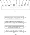
- FIG. 1 is a structural schematic diagram of an ultrasonic radar array according to a first embodiment of the present disclosure. As shown in FIG. 1 , the ultrasonic radar array comprises 10 ultrasonic radars which each comprise an ultrasonic wave transmitting circuit and an ultrasonic wave receiving circuit.
- Ultrasonic radars #9, #7, #5, #3, #1, #2, #4, #6, #8, and #10 are evenly mounted on a front bumper of the unmanned vehicle. Starting from the ultrasonic radar #9 which is on the left-most side and rotated counterclockwise by an angle 4 ⁇ with a state upon horizontal mounting as a reference, each ultrasonic radar is rotated clockwise by an angle ⁇ until the ultrasonic radar #10 on the right-most side is rotated clockwise by an angle 4 ⁇ with the state upon horizontal mounting as a reference.
- ultrasonic radar #1 is horizontally mounted on the left side of a center of the front bumper
- ultrasonic radar #2 is horizontally mounted on the right side of the center of the front bumper
- ultrasonic radar #3 is mounted on the left side of ultrasonic radar #1 and rotated counterclockwise by an angle ⁇ with the state upon horizontal mounting as the reference
- ultrasonic radar #4 is mounted on the right side of ultrasonic radar #2 and rotated clockwise by an angle ⁇ with the state upon horizontal mounting as the reference
- ultrasonic radar #5 is mounted on the left side of ultrasonic radar #3 and rotated counterclockwise by an angle 2 ⁇ with the state upon horizontal mounting as the reference
- ultrasonic radar #6 is mounted on the right side of ultrasonic radar #4 and rotated clockwise by an angle 2 ⁇ with the state upon horizontal mounting as the reference
- ultrasonic radar #7 is mounted on the left side of ultrasonic radar #5 and rotated counterclockwise by an angle 3 ⁇ with the state
- ⁇ is preferably 5° .
- a horizontal beam angle of the ultrasonic radars is 45° , and a coverage range of the ultrasonic radars is 0-3.5m.
- the ten ultrasonic radars have a certain fault-tolerance capability because their coverage ranges are superimposed.
- the superimposed coverage ranges of the ultrasonic radars need to be determined to facilitate error detection and correction in the subsequent obstacle detection procedure.
- the coverage range of each ultrasonic radar in its own coordinate system is determined according to a mathematic model of a detection distance and detection shape of each ultrasonic radar.
- the coordinate system of each ultrasonic radar is unified into a reference coordinate system.
- the reference coordinate system is a vehicle coordinate system.
- Matrix transformation is performed through a relationship between initial space configuration of each ultrasonic radar on the unmanned vehicle and the vehicle coordinate system.
- the initial space configuration of the ultrasonic radar is already known in advance and may be obtained according to measurement data of the plurality of ultrasonic radars on the vehicle body of the unmanned vehicle.
- the coverage ranges of the ultrasonic radars after being unified into the reference coordinate system are superimposed in a preset detection region.
- the gridded preset detection region is in a range of 15-350cm in front of and lateral front side of the vehicle body.
- ultrasonic radars function to detect obstacles and have a high tolerance for missed detection. Therefore, even though only ultrasonic radar #9 returns obstacle information, it is also believed that the obstacle is located in a single ultrasonic radar coverage range in the coverage range of ultrasonic radar #9, rather than that detection omission appears in its adjacent ultrasonic radar #7 or ultrasonic radar #5.
- the fault-tolerance capability in obstacle detection is achieved through the ultrasonic radar array according to the present embodiment and through the superimposition of coverage ranges of the plurality of ultrasonic radars.
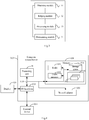
- FIG. 2 is a flow chart of a method for detecting an obstacle with an ultrasonic radar array according to a second embodiment of the present disclosure. As shown in FIG. 2 , the method comprises: Step S21: obtaining obstacle information collected by ultrasonic radars in the ultrasonic radar array described in the first embodiment in an obstacle scenario, and converting coordinates into a vehicle body coordinate system;
- the initial space configuration of the ultrasonic radar is already known in advance and may be obtained according to measurement data of the plurality of ultrasonic radars on the vehicle body of the unmanned vehicle. Coordinates of targets in respective radar coordinate systems are converted into the vehicle body coordinate system.
- a basic principle of the preset rule is that when one ultrasonic radar falsely detects and if its adjacent ultrasonic radars do not falsely detect, the obstacle coordinates will not be returned; when one ultrasonic radar misses detection and if its adjacent ultrasonic radars do not miss detection, the obstacle coordinates are returned.
- the rule for judging false detection is as follows:
- the coverage range of the ultrasonic radar has two ultrasonic radar coverage ranges, for example, ultrasonic radar #7 and ultrasonic radar #8, its detection range at least overlaps one adjacent ultrasonic radar coverage range, for example, ultrasonic radar #7 returns the obstacle coordinates, the adjacent ultrasonic radar #9 does not return the obstacle coordinates, and the adjacent ultrasonic radar #5 neither returns the obstacle coordinates; in this case, there are many possibilities: if the obstacle is located in two ultrasonic radar coverage ranges in the coverage range of the ultrasonic radar #7, namely, coverage ranges overlapping ultrasonic radar #9, it is possible that ultrasonic radar #9 misses detection or ultrasonic radar #7 falsely detects.
- the obstacle is located in three ultrasonic radar coverage ranges in the coverage range of the ultrasonic radar #7, namely, coverage ranges overlapping ultrasonic radar #9 and ultrasonic radar #5, it is possible that ultrasonic radar #7 falsely detects because none of ultrasonic radar #9 and ultrasonic radar #5 returns the obstacle coordinates.
- the obstacle is located in two ultrasonic radar coverage ranges in the coverage range of the ultrasonic radar #7, namely, coverage ranges overlapping ultrasonic radar #9, and ultrasonic radar 9 misses detection. The reason is that if false detection happens, the false detection is only likely to cause the stop of the unmanned vehicle, and a detection result at next time is awaited; if missed detection happens, the missed detection is much likely to cause collision
- ultrasonic radar #5 ultrasonic radar #3, ultrasonic radar #1, ultrasonic radar#2, ultrasonic radar #4, and ultrasonic radar #6
- the detection range of the ultrasonic radar overlaps the coverage ranges of two adjacent ultrasonic radars, in the case that none of the two adjacent ultrasonic radars returns an obstacle detection result, it is believed that the false detection happens to the to-be-judged ultrasonic radar.
- the number of adjacent ultrasonic radars returning the obstacle coordinates is one, judge whether coverage ranges of two ultrasonic radars exist in the coverage range of the to-be-judged ultrasonic radar; If NO, it is believed that missed detection happens to the ultrasonic radar, for example, coverage ranges of three ultrasonic radars overlap in the coverage range of ultrasonic radar #1; if only one adjacent ultrasonic radar #2 returns the obstacle coordinates, its adjacent ultrasonic radar # 3 or #4 should return the obstacle coordinates; if the obstacle coordinates are not returned, missed detection happens to its adjacent ultrasonic radar #3 or #4; If YES, further judge whether the coverage range of the adjacent ultrasonic radar returning the obstacle coordinates has two ultrasonic radar coverage ranges with the to-be-judged ultrasonic radar; If YES, false detection does not exist; for example, if the to-be-judged ultrasonic radar #9 and the adjacent ultrasonic radar #7 have two ultrasonic radar coverage ranges overlapping, the obstacle is located in the overlapping region; If NO,
- the to-be-judged ultrasonic radar #7 returns the obstacle coordinates
- the adjacent ultrasonic radar #5 returns the obstacle coordinates
- the ultrasonic radar #7 and ultrasonic radar #5 only have three ultrasonic radar coverage ranges overlapping, this proves that missed detection happens to ultrasonic radar #9 or ultrasonic radar #3.
- the rule for judging the missed detection is as follows:
- ultrasonic radar #1 does not return the obstacle coordinates
- its adjacent ultrasonic radars #3 and #2 both return the obstacle coordinates
- ultrasonic radar #1 and ultrasonic radar #3 and ultrasonic radar #2 have three ultrasonic radar coverage ranges
- missed detection happens to ultrasonic radar 1.
- the coverage ranges of the to-be-judged ultrasonic radar and two adjacent ultrasonic radars returning the obstacle coordinates have three ultrasonic radar coverage ranges; if there are three ultrasonic radar coverage ranges, it is believed that missed detection happens to the to-be-judged ultrasonic radar; if there are not three ultrasonic radar coverage ranges, it is not believed that missed detection happens to the to-be-judged ultrasonic radar.
- false detection or missed detection of the to-be-judged ultrasonic radar is adjusted according to the mutual overlap of coverage ranges of the to-be-judged ultrasonic radar and its adjacent ultrasonic radars, and the obstacle coordinates returned by the ultrasonic radars in the ultrasonic radar array.
- Step S23 processing the obstacle information collected by the ultrasonic radars in the ultrasonic radar array according to a judgement result.
- the obstacle information collected by the ultrasonic radar that falsely detects is deleted.
- the obstacle information collected by the ultrasonic radar that misses detection may be obtained according to the obstacle information returned by its adjacent ultrasonic radars.
- the obstacle coordinates returned by the adjacent ultrasonic radar is taken as the obstacle coordinates collected by the to-be-judged ultrasonic radar.
- the distance data returned by the two or more ultrasonic radars are fused by a triangulation-based fusion method.
- the obstacle coordinates corresponding to the ultrasonic radar #1 are determined according to the obstacle coordinates returned by its adjacent ultrasonic radars #3 and #2.
- the obstacle information collected by the ultrasonic radars in the ultrasonic radar array are not processed.
- Step S24 determining a position of the obstacle in the vehicle body coordinate system according to the processed obstacle information collected by the ultrasonic radars, and performing unmanned vehicle decision-making according to the position of the obstacle.
- a single ultrasonic radar returns the obstacle coordinates, it is determined that the obstacle is located on a portion where a circular arc with the single ultrasonic radar as the origin and with the obstacle distance as a radius is located in the single ultrasonic radar coverage range of the ultrasonic radar.
- the distance data returned by the two ultrasonic radars are fused by the triangulation-based fusion method to obtain edge fixed point information of the obstacle.
- fusion processing may be performed by a circumcircle method.
- the plurality of ultrasonic radars with the ultrasonic radar as the origin and the obstacle distance as the radius should intersect at one point.
- the plurality of segments of circular arcs do not intersect at one point due to factors such as measurement errors and noise interference.
- each ultrasonic radars are taken as a group, each group have three segments of circular arcs intersecting at three points, a center of the circumcircle of the three points is taken as a final measurement result of the three ultrasonic radars, and finally, an average value of final measurement results of groups of ultrasonic radars is finally solved as a final fusion result.
- FIG. 3 is a structural schematic diagram of a system for detecting an obstacle with an ultrasonic radar array according to a third embodiment of the present disclosure. As shown in FIG. 3 , the system comprises:
- a judging module 32 configured to judge false detection and missed detection for the obstacle information collected by ultrasonic radars in the ultrasonic radar array according a preset rule.
- a basic principle of the preset rule is that when one ultrasonic radar falsely detects and if its adjacent ultrasonic radars do not falsely detect, the obstacle coordinates will not be returned; when one ultrasonic radar misses detection and if its adjacent ultrasonic radars do not miss detection, the obstacle coordinates are returned.
- the rule for judging false detection is as follows:
- the coverage range of the ultrasonic radar has two ultrasonic radar coverage ranges, for example, ultrasonic radar #7 and ultrasonic radar #8, its detection range at least overlaps one adjacent ultrasonic radar coverage range, for example, ultrasonic radar #7 returns the obstacle coordinates, the adjacent ultrasonic radar #9 does not return the obstacle coordinates, and the adjacent ultrasonic radar #5 neither returns the obstacle coordinates; in this case, there are many possibilities: if the obstacle is located in two ultrasonic radar coverage ranges in the coverage range of the ultrasonic radar #7, namely, coverage ranges overlapping ultrasonic radar #9, it is possible that ultrasonic radar #9 misses detection or ultrasonic radar #7 falsely detects.
- the obstacle is located in three ultrasonic radar coverage ranges in the coverage range of the ultrasonic radar #7, namely, coverage ranges overlapping ultrasonic radar #9 and ultrasonic radar #5, it is possible that ultrasonic radar #7 falsely detects because none of ultrasonic radar #9 and ultrasonic radar #5 returns the obstacle coordinates.
- the obstacle is located in two ultrasonic radar coverage ranges in the coverage range of the ultrasonic radar #7, namely, coverage ranges overlapping ultrasonic radar #9, and ultrasonic radar 9 misses detection. The reason is that if false detection happens, the false detection is only likely to cause the stop of the unmanned vehicle, and a detection result at next time is awaited; if missed detection happens, the missed detection is much likely to cause collision
- ultrasonic radar #5 ultrasonic radar #3, ultrasonic radar #1, ultrasonic radar#2, ultrasonic radar #4, and ultrasonic radar #6
- the detection range of the ultrasonic radar overlaps the coverage ranges of two adjacent ultrasonic radars, in the case that none of the two adjacent ultrasonic radars returns an obstacle detection result, it is believed that the false detection happens to the to-be-judged ultrasonic radar.
- the number of adjacent ultrasonic radars returning the obstacle coordinates is one, judge whether coverage ranges of two ultrasonic radars exist in the coverage range of the to-be-judged ultrasonic radar; If NO, it is believed that missed detection happens to the ultrasonic radar, for example, coverage ranges of three ultrasonic radars overlap in the coverage range of ultrasonic radar #1; if only one adjacent ultrasonic radar #2 returns the obstacle coordinates, its adjacent ultrasonic radar # 3 or #4 should return the obstacle coordinates; if the obstacle coordinates are not returned, missed detection happens to its adjacent ultrasonic radar #3 or #4; If YES, further judge whether the coverage range of the adjacent ultrasonic radar returning the obstacle coordinates has two ultrasonic radar coverage ranges with the to-be-judged ultrasonic radar; If YES, false detection does not exist; for example, if the to-be-judged ultrasonic radar #9 and the adjacent ultrasonic radar #7 have two ultrasonic radar coverage ranges overlapping, the obstacle is located in the overlapping region; If NO,
- the to-be-judged ultrasonic radar #7 returns the obstacle coordinates
- the adjacent ultrasonic radar #5 returns the obstacle coordinates
- the ultrasonic radar #7 and ultrasonic radar #5 only have three ultrasonic radar coverage ranges overlapping, this proves that missed detection happens to ultrasonic radar #9 or ultrasonic radar #3.
- the rule for judging the missed detection is as follows:
- ultrasonic radar #1 does not return the obstacle coordinates
- its adjacent ultrasonic radars #3 and #2 both return the obstacle coordinates
- ultrasonic radar #1 and ultrasonic radar #3 and ultrasonic radar #2 have three ultrasonic radar coverage ranges
- the coverage ranges of the to-be-judged ultrasonic radar and two adjacent ultrasonic radars returning the obstacle coordinates have three ultrasonic radar coverage ranges; if there are three ultrasonic radar coverage ranges, it is believed that missed detection happens to the to-be-judged ultrasonic radar; if there are not three ultrasonic radar coverage ranges, it is not believed that missed detection happens to the to-be-judged ultrasonic radar.
- false detection or missed detection of the to-be-judged ultrasonic radar is adjusted according to the mutual overlap of coverage ranges of the to-be-judged ultrasonic radar and its adjacent ultrasonic radars, and the obstacle coordinates returned by the ultrasonic radars in the ultrasonic radar array.
- a processing module 33 configured to process the obstacle information collected by the ultrasonic radars in the ultrasonic radar array according to the judgement result.
- the obstacle information collected by the ultrasonic radar that falsely detects is deleted.
- the obstacle information collected by the ultrasonic radar that misses detection may be obtained according to the obstacle information returned by its adjacent ultrasonic radars.
- the obstacle coordinates returned by the adjacent ultrasonic radar is taken as the obstacle coordinates collected by the to-be-judged ultrasonic radar.
- the distance data returned by the two or more ultrasonic radars are fused by a triangulation-based fusion method.
- the obstacle coordinates corresponding to the ultrasonic radar #1 are determined according to the obstacle coordinates returned by its adjacent ultrasonic radars #3 and #2.
- the obstacle information collected by the ultrasonic radars in the ultrasonic radar array are not processed.
- a determining module 34 configured to determine a position of the obstacle in the vehicle body coordinate system according to the processed obstacle information collected by the ultrasonic radars, and perform unmanned vehicle decision-making according to the position of the obstacle.
- a single ultrasonic radar returns the obstacle coordinates, it is determined that the obstacle is located on a portion where a circular arc with the single ultrasonic radar as the origin and with the obstacle distance as a radius is located in the single ultrasonic radar coverage range of the ultrasonic radar.
- the distance data returned by the two ultrasonic radars are fused by the triangulation-based fusion method to obtain edge fixed point information of the obstacle.
- fusion processing may be performed by a circumcircle method.
- the plurality of ultrasonic radars with the ultrasonic radar as the origin and the obstacle distance as the radius should intersect at one point.
- the plurality of segments of circular arcs do not intersect at one point due to factors such as measurement errors and noise interference.
- each ultrasonic radars are taken as a group, each group have three segments of circular arcs intersecting at three points, a center of a circumcircle of the three points is taken as a final measurement result of the three ultrasonic radars, and finally, an average value of final measurement results of groups of ultrasonic radars is finally solved as a final fusion result.
- the revealed method and apparatus may be implemented in other ways.
- the above-described embodiments for the apparatus are only exemplary, e.g., the division of the units is merely logical one, and, in reality, they can be divided in other ways upon implementation.
- a plurality of units or components may be combined or integrated into another system, or some features may be neglected or not executed.
- mutual coupling or direct coupling or communicative connection as displayed or discussed may be performed via some interfaces
- indirect coupling or communicative connection of means or units may be electrical, mechanical or in other forms.
- the units described as separate parts may be or may not be physically separated, the parts shown as units may be or may not be physical units, i.e., they can be located in one place, or distributed in a plurality of network units. One can select some or all the units to achieve the purpose of the embodiment according to the actual needs.
- functional units can be integrated in one processing unit, or they can be separate physical presences; or two or more units can be integrated in one unit.
- the integrated unit described above can be realized in the form of hardware, or they can be realized with hardware and software functional units.
- FIG. 4 illustrates a block diagram of an example computer system/server 012 adapted to implement an implementation mode of the present disclosure.
- the computer system/server 012 shown in FIG. 4 is only an example, and should not bring any limitation to the functions and use scope of the embodiments of the present disclosure.
- the computer system/server 012 is shown in the form of a general-purpose computing device.
- the components of the computer system/server 012 may include, but are not limited to, one or more processors or processing units 016, a system memory 028, and a bus 018 that couples various system components including the system memory 028 and the processing unit 016.
- Bus 018 represents one or more of several types of bus structures, including a memory bus or memory controller, a peripheral bus, an accelerated graphics port, and a processor or local bus using any of a variety of bus architectures.
- bus architectures include Industry Standard Architecture (ISA) bus, Micro Channel Architecture (MCA) bus, Enhanced ISA (EISA) bus, Video Electronics Standards Association (VESA) local bus, and Peripheral Component Interconnect (PCI) bus.
- Computer system/server 012 typically includes a variety of computer system readable media. Such media may be any available media that is accessible by computer system/server 012, and it includes both volatile and non-volatile media, removable and non-removable media.
- Memory 028 can include computer system readable media in the form of volatile memory, such as random access memory (RAM) 030 and/or cache memory 032.
- Computer system/server 012 may further include other removable/non-removable, volatile/non-volatile computer system storage media.
- storage system 034 can be provided for reading from and writing to a non-removable, non-volatile magnetic media (not shown in FIG. 4 and typically called a "hard drive").
- a magnetic disk drive for reading from and writing to a removable, non-volatile magnetic disk (e.g., a "floppy disk"), and an optical disk drive for reading from or writing to a removable, non-volatile optical disk such as a CD-ROM, DVD-ROM or other optical media
- each drive can be connected to bus 018 by one or more data media interfaces.
- the memory 028 may include at least one program product having a set of (e.g., at least one) program modules that are configured to carry out the functions of embodiments of the present disclosure.
- Program/utility 040 having a set of (at least one) program modules 042, may be stored in the system memory 028 by way of example, and not limitation, as well as an operating system, one or more disclosure programs, other program modules, and program data. Each of these examples or a certain combination thereof might include an implementation of a networking environment.
- Program modules 042 generally carry out the functions and/or methodologies of embodiments of the present disclosure.
- Computer system/server 012 may also communicate with one or more external devices 014 such as a keyboard, a pointing device, a display 024, etc.; with one or more devices that enable a user to interact with computer system/server 012; and/or with any devices (e.g., network card, modem, etc.) that enable computer system/server 012 to communicate with one or more other computing devices. Such communication can occur via Input/Output (I/O) interfaces 022. Still yet, computer system/server 012 can communicate with one or more networks such as a local area network (LAN), a general wide area network (WAN), and/or a public network (e.g., the Internet) via network adapter 020.
- LAN local area network
- WAN wide area network
- public network e.g., the Internet
- network adapter 020 communicates with the other communication modules of computer system/server 012 via bus 018.
- bus 018 It should be understood that although not shown in FIG. 4 , other hardware and/or software modules could be used in conjunction with computer system/server 012. Examples, include, but are not limited to: microcode, device drivers, redundant processing units, external disk drive arrays, RAID systems, tape drives, and data archival storage systems, etc.
- the processing unit 016 executes the functions and/or methods described in the embodiments of the present disclosure by running the programs stored in the system memory 028.
- the aforesaid computer program may be arranged in the computer storage medium, namely, the computer storage medium is encoded with the computer program.
- the computer program when executed by one or more computers, enables one or more computers to execute the flow of the method and/or operations of the apparatus as shown in the above embodiments of the present disclosure.
- a propagation channel of the computer program is no longer limited to tangible medium, and it may also be directly downloaded from the network.
- the computer-readable medium of the present embodiment may employ any combinations of one or more computer-readable media.
- the machine readable medium may be a machine readable signal medium or a machine readable storage medium.
- a machine readable medium may include, but not limited to, an electronic, magnetic, optical, electromagnetic, infrared, or semiconductor system, apparatus, or device, or any suitable combination of the foregoing.
- the machine readable storage medium can be any tangible medium that include or store programs for use by an instruction execution system, apparatus or device or a combination thereof.
- the computer-readable signal medium may be included in a baseband or serve as a data signal propagated by part of a carrier, and it carries a computer-readable program code therein. Such propagated data signal may take many forms, including, but not limited to, electromagnetic signal, optical signal or any suitable combinations thereof.
- the computer-readable signal medium may further be any computer-readable medium besides the computer-readable storage medium, and the computer-readable medium may send, propagate or transmit a program for use by an instruction execution system, apparatus or device or a combination thereof.
- the program codes included by the computer-readable medium may be transmitted with any suitable medium, including, but not limited to radio, electric wire, optical cable, RF or the like, or any suitable combination thereof.
- Computer program code for carrying out operations disclosed herein may be written in one or more programming languages or any combination thereof. These programming languages include an object oriented programming language such as Java, Smalltalk, C++ or the like, and conventional procedural programming languages, such as the "C" programming language or similar programming languages.
- the program code may execute entirely on the user's computer, partly on the user's computer, as a stand-alone software package, partly on the user's computer and partly on a remote computer or entirely on the remote computer or server.
- the remote computer may be connected to the user's computer through any type of network, including a local area network (LAN) or a wide area network (WAN), or the connection may be made to an external computer (for example, through the Internet using an Internet Service Provider).
- LAN local area network
- WAN wide area network
- Internet Service Provider for example, AT&T, MCI, Sprint, EarthLink, MSN, GTE, etc.
Landscapes
- Engineering & Computer Science (AREA)
- Radar, Positioning & Navigation (AREA)
- Remote Sensing (AREA)
- Physics & Mathematics (AREA)
- Computer Networks & Wireless Communication (AREA)
- General Physics & Mathematics (AREA)
- Acoustics & Sound (AREA)
- Measurement Of Velocity Or Position Using Acoustic Or Ultrasonic Waves (AREA)
- Image Analysis (AREA)
Abstract
Description
- The present disclosure claims priority to the
Chinese patent application No. 201910036318.8 - The present disclosure relates to the field of automatic control, and particularly to an ultrasonic radar array, and obstacle detection method and system.
- Unmanned vehicles are a kind of intelligent vehicles, also referred to as wheeled mobile robots, and implement unmanned driving mainly depending on an intelligent driving instrument in the vehicle with a computer system as a core. The unmanned vehicle integrates many techniques such as automatic control, architecture, artificial intelligence and vision computing, are products of advanced development of computer sciences, mode recognition and intelligent control techniques, are also an important index for measuring a country's science and technological power and industrial level, and have a broad application prospect in the fields such as national defense and national economy.
- Ultrasonic waves have characteristics such as better directivity, better applicability and strong penetration capability, and therefore are usually uploaded on the unmanned vehicle to function to avoid the obstacle. A conventional ultrasonic radar array applied to the unmanned vehicle is generally mounted on a front/rear bumper of the vehicle in a number of four. The ultrasonic radar array detects the obstacle unstably with false detection and missed detection, cannot precisely describe the position of the obstacle, usually has a large blind region in transverse detection, and has possible safety hazards; it is very difficult for the ultrasonic radar array to meet the recognition requirements in the field of unmanned vehicles that have high requirements for precision, which reduces the safety of the driving of the unmanned vehicles.
- A plurality of aspects of the present disclosure provide an ultrasonic radar array, an obstacle detection method and system, to improve the accuracy and reliability of ultrasonic obstacle detection, cover the transverse blind region of the unmanned vehicles and improve the driving safety.
- An aspect of the present disclosure provides an ultrasonic radar array, comprising N ultrasonic radars evenly mounted on a bumper of an unmanned vehicle, the N ultrasonic radars being distributed from a center to outer sides, with rotation angles gradually increasing towards the outer sides; wherein N is a positive integer.
- The above aspect and any possible implementation further provide an implementation: if N is an even number, a first ultrasonic radar is horizontally mounted on a left side of a center of the bumper, and a second ultrasonic radar is horizontally mounted on a right side of the center of the bumper; (N-2)/2 ultrasonic radars are mounted on the left side of the first ultrasonic radar from the center to the outer sides with a previous ultrasonic radar as a reference and rotate counterclockwise by an angle of α in turn; (N-2)/2 ultrasonic radars are mounted on the right side of the second ultrasonic radar from the center to the outer sides with a previous ultrasonic radar as a reference and rotate clockwise by an angle of α in turn;
if N is an odd number, a first ultrasonic radar is horizontally mounted at a center of the bumper, (N-1)/2 ultrasonic radars are mounted on the left side of the first ultrasonic radar from the center to the outer sides with a previous ultrasonic radar as a reference and rotate counterclockwise by an angle of α in turn; (N-1)/2 ultrasonic radars are mounted on the right side of the first ultrasonic radar from the center to the outer sides with a previous ultrasonic radar as a reference and rotate clockwise by an angle of α in turn. - The above aspect and any possible implementation further provide an implementation: the number N and rotation angle α of ultrasonic radars are determined according to a mathematic model of a detection distance and detection shape of each ultrasonic radar, to ensure triple redundancy existing in the coverage ranges of the ultrasonic radars.
- The present invention provides a method for detecting an obstacle with an ultrasonic radar array, comprising:
- obtaining obstacle information collected by ultrasonic radars in an ultrasonic radar array in an obstacle scenario;
- judging false detection and missed detection for the obstacle information collected by ultrasonic radars according a preset rule;
- processing the obstacle information collected by the ultrasonic radars according to the judgement result;
- determining a position of the obstacle according to the processed obstacle information collected by the ultrasonic radars.
- The above aspect and any possible implementation further provide an implementation: the preset rule is judging whether false detection and missed detection happen to the to-be-judged ultrasonic radar according to whether adjacent ultrasonic radars of the to-be-judged ultrasonic radar return the obstacle coordinates.
- The above aspect and any possible implementation further provide an implementation: an adjacent ultrasonic radar of the to-be-judged ultrasonic radar is an ultrasonic radar which is immediately close to the to-be-judged ultrasonic radar on either side of the to-be-judged ultrasonic radar or an ultrasonic radar which is separated from the to-be-judged ultrasonic radar by one ultrasonic radar.
- The above aspect and any possible implementation further provide an implementation: the preset rule for judging false detection comprises:
- in a case that no adjacent ultrasonic radars of the to-be-judged ultrasonic radar return obstacle coordinates, if the coverage range of the to-be-judged ultrasonic radar has a single ultrasonic radar coverage range or two ultrasonic radar coverage ranges overlapping, false detection does not happen; if the coverage range of the to-be-judged ultrasonic radar only has three ultrasonic radar coverage ranges overlapping, false detection happens;
- in a case that one adjacent ultrasonic radar of the to-be-judged ultrasonic radar returns the obstacle coordinates, false detection does not happen;
- in a case that two adjacent ultrasonic radars of the to-be-judged ultrasonic radar return the obstacle coordinates, false detection does not happen.
- The above aspect and any possible implementation further provide an implementation: the preset rule for judging missed detection comprises:
- in a case that no adjacent ultrasonic radars of the to-be-judged ultrasonic radar returns the obstacle coordinates, missed detection does not happen to the to-be-judged ultrasonic radar;
- in a case that one adjacent ultrasonic radar of the to-be-judged ultrasonic radar returns the obstacle coordinates, if the coverage ranges of the to-be-judged ultrasonic radar and the adjacent ultrasonic radar returning the obstacle coordinates have two ultrasonic radar coverage ranges overlapping, missed detection happens; if the coverage ranges of the to-be-judged ultrasonic radar and the adjacent ultrasonic radar returning the obstacle coordinates only have three ultrasonic radar coverage ranges overlapping, missed detection does not happen;
- in a case that two adjacent ultrasonic radars of the to-be-judged ultrasonic radar return the obstacle coordinates, if the coverage ranges of the to-be-judged ultrasonic radar and the adjacent ultrasonic radars returning the obstacle coordinates have three ultrasonic radar coverage ranges overlapping, missed detection happens; if the coverage ranges of the to-be-judged ultrasonic radar and the adjacent ultrasonic radars returning the obstacle coordinates do not have three ultrasonic radar coverage ranges overlapping, missed detection does not happen;
- in a case that three or more adjacent ultrasonic radars of the to-be-judged ultrasonic radar return the obstacle coordinates, missed detection happens.
- The above aspect and any possible implementation further provide an implementation: the processing the obstacle information collected by the ultrasonic radars according to the judgement result comprises:
- if false detection exists in the obstacle information collected by the ultrasonic radar, deleting the obstacle information collected by the ultrasonic radar that falsely detects;
- if missed detection exists in the obstacle information collected by the ultrasonic radar, obtaining the obstacle information collected by the ultrasonic radar that misses detection according to the obstacle information returned by its adjacent ultrasonic radars.
- The above aspect and any possible implementation further provide an implementation: the determining a position of the obstacle according to the processed obstacle information collected by the ultrasonic radars comprises:
fusing distance data returned by a plurality ultrasonic radars to obtain the obstacle coordinates. - The present invention provides a system for detecting an obstacle with an ultrasonic radar array, comprising:
- an obtaining module configured to obtain obstacle information collected by ultrasonic radars in an ultrasonic radar array in an obstacle scenario;
- a judging module configured to judge false detection and missed detection for the obstacle information collected by ultrasonic radars according a preset rule;
- a processing module configured to process the obstacle information collected by the ultrasonic radars according to the judgement result;
- a determining module configured to determine a position of the obstacle according to the processed obstacle information collected by the ultrasonic radars.
- The above aspect and any possible implementation further provide an implementation: the preset rule is judging whether false detection and missed detection happen to the to-be-judged ultrasonic radar according to whether adjacent ultrasonic radars of the to-be-judged ultrasonic radar return the obstacle coordinates.
- The above aspect and any possible implementation further provide an implementation: an adjacent ultrasonic radar of the to-be-judged ultrasonic radar is an ultrasonic radar which is immediately close to the to-be-judged ultrasonic radar on either side of the to-be-judged ultrasonic radar or an ultrasonic radar which is separated from the to-be-judged ultrasonic radar by one ultrasonic radar.
- The above aspect and any possible implementation further provide an implementation: the preset rule for judging false detection comprises:
- in a case that no adjacent ultrasonic radars of the to-be-judged ultrasonic radar return obstacle coordinates, if the coverage range of the to-be-judged ultrasonic radar has a single ultrasonic radar coverage range or two ultrasonic radar coverage ranges overlapping, false detection does not happen; if the coverage range of the to-be-judged ultrasonic radar only has three ultrasonic radar coverage ranges overlapping, false detection happens;
- in a case that one adjacent ultrasonic radar of the to-be-judged ultrasonic radar returns the obstacle coordinates, false detection does not happen;
- in a case that two adjacent ultrasonic radars of the to-be-judged ultrasonic radar return the obstacle coordinates, false detection does not happen.
- The above aspect and any possible implementation further provide an implementation: the preset rule for judging missed detection comprises:
- in a case that no adjacent ultrasonic radars of the to-be-judged ultrasonic radar return the obstacle coordinates, missed detection does not happen to the to-be-judged ultrasonic radar;
- in a case that one adjacent ultrasonic radar of the to-be-judged ultrasonic radar returns the obstacle coordinates, if the coverage ranges of the to-be-judged ultrasonic radar and the adjacent ultrasonic radar returning the obstacle coordinates have two ultrasonic radar coverage ranges overlapping, missed detection happens; if the coverage ranges of the to-be-judged ultrasonic radar and the adjacent ultrasonic radar returning the obstacle coordinates only have three ultrasonic radar coverage ranges overlapping, missed detection does not happen;
- in a case that two adjacent ultrasonic radars of the to-be-judged ultrasonic radar return the obstacle coordinates, if the coverage ranges of the to-be-judged ultrasonic radar and the adjacent ultrasonic radars returning the obstacle coordinates have three ultrasonic radar coverage ranges overlapping, missed detection happens; if the coverage ranges of the to-be-judged ultrasonic radar and the adjacent ultrasonic radars returning the obstacle coordinates do not have three ultrasonic radar coverage ranges overlapping, missed detection does not happen;
- in a case that three or more adjacent ultrasonic radars of the to-be-judged ultrasonic radar return the obstacle coordinates, missed detection happens.
- The above aspect and any possible implementation further provide an implementation: the processing module is specifically configured to:
- if false detection exists in the obstacle information collected by the ultrasonic radar, delete the obstacle information collected by the ultrasonic radar that falsely detects;
- if missed detection exists in the obstacle information collected by the ultrasonic radar, obtain the obstacle information collected by the ultrasonic radar that misses detection according to the obstacle information returned by its adjacent ultrasonic radars.
- The above aspect and any possible implementation further provides, an implementation: the determining module is specifically configured to:
fuse distance data returned by a plurality ultrasonic radars to obtain the obstacle coordinates. - A further aspect of the present invention provides a computer device, comprising a memory, a processor and a computer program which is stored on the memory and runs on the processor, the processor, upon executing the program, implementing the above-mentioned method.
- A further aspect of the present invention provides a computer-readable storage medium on which a computer program is stored, the program, when executed by the processor, implementing the aforesaid method.
- As known from the above technical solutions, embodiment of the present application may effectively judge false detection and missed detection happening to the ultrasonic radars in the ultrasonic radar array, precisely determine the position of the obstacle and improve the driving safety of the unmanned vehicle.
- To describe technical solutions of embodiments of the present disclosure more clearly, figures to be used in the embodiments or in depictions regarding the prior art will be described briefly. Obviously, the figures described below are only some embodiments of the present disclosure. Those having ordinary skill in the art appreciate that other figures may be obtained from these figures without making inventive efforts.
-
FIG. 1 is a structural schematic diagram of an ultrasonic radar array according to a first embodiment of the present disclosure; -
FIG. 2 is a flow chart of a method for detecting an obstacle with an ultrasonic radar array according to a second embodiment of the present disclosure; -
FIG. 3 is a structural schematic diagram of a system for detecting an obstacle with an ultrasonic radar array according to a third embodiment of the present disclosure; -
FIG. 4 illustrates a block diagram of an example computer system/server 012 adapted to implement an implementation mode of the present disclosure. - The present disclosure will be described in detail with reference to figures and specific embodiments to make objects, technical solutions and advantages of the present invention more apparent.
- To make objectives, technical solutions and advantages of embodiments of the present disclosure clearer, technical solutions of embodiment of the present disclosure will be described clearly and completely with reference to figures in embodiments of the present disclosure. Obviously, embodiments described here are partial embodiments of the present disclosure, not all embodiments. All other embodiments obtained by those having ordinary skill in the art based on the embodiments of the present disclosure, without making any inventive efforts, fall within the protection scope of the present disclosure.
-
FIG. 1 is a structural schematic diagram of an ultrasonic radar array according to a first embodiment of the present disclosure. As shown inFIG. 1 , the ultrasonic radar array comprises 10 ultrasonic radars which each comprise an ultrasonic wave transmitting circuit and an ultrasonic wave receiving circuit. -
Ultrasonic radars # 9, #7, #5, #3, #1, #2, #4, #6, #8, and #10 are evenly mounted on a front bumper of the unmanned vehicle. Starting from theultrasonic radar # 9 which is on the left-most side and rotated counterclockwise by anangle 4 α with a state upon horizontal mounting as a reference, each ultrasonic radar is rotated clockwise by an angle α until theultrasonic radar # 10 on the right-most side is rotated clockwise by anangle 4 α with the state upon horizontal mounting as a reference. - Specifically, the ten ultrasonic radars are evenly mounted on the front bumper of the unmanned vehicle, ultrasonic radar #1 is horizontally mounted on the left side of a center of the front bumper; ultrasonic radar #2 is horizontally mounted on the right side of the center of the front bumper; ultrasonic radar #3 is mounted on the left side of ultrasonic radar #1 and rotated counterclockwise by an angle α with the state upon horizontal mounting as the reference; ultrasonic radar #4 is mounted on the right side of ultrasonic radar #2 and rotated clockwise by an angle α with the state upon horizontal mounting as the reference; ultrasonic radar #5 is mounted on the left side of ultrasonic radar #3 and rotated counterclockwise by an angle 2 α with the state upon horizontal mounting as the reference; ultrasonic radar #6 is mounted on the right side of ultrasonic radar #4 and rotated clockwise by an angle 2 α with the state upon horizontal mounting as the reference; ultrasonic radar #7 is mounted on the left side of ultrasonic radar #5 and rotated counterclockwise by an angle 3 α with the state upon horizontal mounting as the reference; ultrasonic radar #8 is mounted on the right side of ultrasonic radar #6 and rotated clockwise by an angle 3 α with the state upon horizontal mounting as the reference; ultrasonic radar #9 is mounted on the left side of ultrasonic radar #5 and rotated counterclockwise by an angle 4 α with the state upon horizontal mounting as the reference; ultrasonic radar #10 is mounted on the right side of ultrasonic radar #8 and rotated clockwise by an angle 4 α with the state upon horizontal mounting as the reference.
- α is preferably 5° . A horizontal beam angle of the ultrasonic radars is 45° , and a coverage range of the ultrasonic radars is 0-3.5m.
- The ten ultrasonic radars have a certain fault-tolerance capability because their coverage ranges are superimposed. The superimposed coverage ranges of the ultrasonic radars need to be determined to facilitate error detection and correction in the subsequent obstacle detection procedure.
- Preferably, the coverage range of each ultrasonic radar in its own coordinate system is determined according to a mathematic model of a detection distance and detection shape of each ultrasonic radar.
- The coordinate system of each ultrasonic radar is unified into a reference coordinate system. In the present embodiment, the reference coordinate system is a vehicle coordinate system. Matrix transformation is performed through a relationship between initial space configuration of each ultrasonic radar on the unmanned vehicle and the vehicle coordinate system. The initial space configuration of the ultrasonic radar is already known in advance and may be obtained according to measurement data of the plurality of ultrasonic radars on the vehicle body of the unmanned vehicle.
- The coverage ranges of the ultrasonic radars after being unified into the reference coordinate system are superimposed in a preset detection region. Preferably, the gridded preset detection region is in a range of 15-350cm in front of and lateral front side of the vehicle body.
- It is possible to, through the above steps, obtain the situations about the coverage ranges of the ultrasonic radar array and the overlap of coverage ranges of the ultrasonic radars, for example, to determine a single ultrasonic radar coverage range, the overlap of two ultrasonic radar coverage ranges, the overlap of three ultrasonic radar coverage ranges, and so on.
- It is very necessary to determine the overlap of the ultrasonic radar coverage ranges. For example, if the obstacle appears in the coverage range of the
ultrasonic radar # 9, there might be several cases: the obstacle is located in a single ultrasonic radar coverage range in the coverage range ofultrasonic radar # 9, in the overlap of two ultrasonic radar coverage ranges, and in the overlap of the three ultrasonic radar coverage. In the present embodiment, ultrasonic radars function to detect obstacles and have a high tolerance for missed detection. Therefore, even though onlyultrasonic radar # 9 returns obstacle information, it is also believed that the obstacle is located in a single ultrasonic radar coverage range in the coverage range ofultrasonic radar # 9, rather than that detection omission appears in its adjacentultrasonic radar # 7 orultrasonic radar # 5. - It is feasible that coverage ranges of three ultrasonic radars overlap within a range of 2m in front of the unmanned vehicle, so that a decision-making system votes according to the obstacle information returned by the three ultrasonic radars.
- The fault-tolerance capability in obstacle detection is achieved through the ultrasonic radar array according to the present embodiment and through the superimposition of coverage ranges of the plurality of ultrasonic radars.
-
FIG. 2 is a flow chart of a method for detecting an obstacle with an ultrasonic radar array according to a second embodiment of the present disclosure. As shown inFIG. 2 , the method comprises:
Step S21: obtaining obstacle information collected by ultrasonic radars in the ultrasonic radar array described in the first embodiment in an obstacle scenario, and converting coordinates into a vehicle body coordinate system; - The initial space configuration of the ultrasonic radar is already known in advance and may be obtained according to measurement data of the plurality of ultrasonic radars on the vehicle body of the unmanned vehicle. Coordinates of targets in respective radar coordinate systems are converted into the vehicle body coordinate system.
- S22: judging false detection and missed detection for the obstacle information collected by ultrasonic radars in the ultrasonic radar array according a preset rule.
- A basic principle of the preset rule is that when one ultrasonic radar falsely detects and if its adjacent ultrasonic radars do not falsely detect, the obstacle coordinates will not be returned; when one ultrasonic radar misses detection and if its adjacent ultrasonic radars do not miss detection, the obstacle coordinates are returned.
- The rule for judging false detection is as follows:
- if the obstacle coordinates returned by the ultrasonic radar are received, judge whether adjacent ultrasonic radars of the to-be-judged ultrasonic radar return the obstacle coordinates;
- if adjacent ultrasonic radars of the to-be-judged ultrasonic radar do not return the obstacle coordinates, judge whether the to-be-judged ultrasonic radar has a single ultrasonic radar coverage range, for example,
ultrasonic radar # 9 orultrasonic radar # 10 located at the edge of the ultrasonic radar array; - if the coverage range of the to-be-judged ultrasonic radar has a single ultrasonic radar coverage range, believe that the obstacle appears in the single ultrasonic radar coverage range of the to-be-judged ultrasonic radar; false detection does not appear in the to-be-judged ultrasonic radar.
- If the coverage range of the ultrasonic radar has two ultrasonic radar coverage ranges, for example,
ultrasonic radar # 7 andultrasonic radar # 8, its detection range at least overlaps one adjacent ultrasonic radar coverage range, for example,ultrasonic radar # 7 returns the obstacle coordinates, the adjacentultrasonic radar # 9 does not return the obstacle coordinates, and the adjacentultrasonic radar # 5 neither returns the obstacle coordinates; in this case, there are many possibilities: if the obstacle is located in two ultrasonic radar coverage ranges in the coverage range of theultrasonic radar # 7, namely, coverage ranges overlappingultrasonic radar # 9, it is possible thatultrasonic radar # 9 misses detection orultrasonic radar # 7 falsely detects. If the obstacle is located in three ultrasonic radar coverage ranges in the coverage range of theultrasonic radar # 7, namely, coverage ranges overlappingultrasonic radar # 9 andultrasonic radar # 5, it is possible thatultrasonic radar # 7 falsely detects because none ofultrasonic radar # 9 andultrasonic radar # 5 returns the obstacle coordinates. For the sake of safety, it is believed that the obstacle is located in two ultrasonic radar coverage ranges in the coverage range of theultrasonic radar # 7, namely, coverage ranges overlappingultrasonic radar # 9, andultrasonic radar 9 misses detection. The reason is that if false detection happens, the false detection is only likely to cause the stop of the unmanned vehicle, and a detection result at next time is awaited; if missed detection happens, the missed detection is much likely to cause collision - If only three ultrasonic radar coverage ranges overlap in the coverage range of the ultrasonic radar, for example,
ultrasonic radar # 5,ultrasonic radar # 3,ultrasonic radar # 1,ultrasonic radar# 2,ultrasonic radar # 4, andultrasonic radar # 6, and the detection range of the ultrasonic radar overlaps the coverage ranges of two adjacent ultrasonic radars, in the case that none of the two adjacent ultrasonic radars returns an obstacle detection result, it is believed that the false detection happens to the to-be-judged ultrasonic radar. - If the number of adjacent ultrasonic radars returning the obstacle coordinates is one, judge whether coverage ranges of two ultrasonic radars exist in the coverage range of the to-be-judged ultrasonic radar;
If NO, it is believed that missed detection happens to the ultrasonic radar, for example, coverage ranges of three ultrasonic radars overlap in the coverage range ofultrasonic radar # 1; if only one adjacentultrasonic radar # 2 returns the obstacle coordinates, its adjacentultrasonic radar # 3 or #4 should return the obstacle coordinates; if the obstacle coordinates are not returned, missed detection happens to its adjacentultrasonic radar # 3 or #4;
If YES, further judge whether the coverage range of the adjacent ultrasonic radar returning the obstacle coordinates has two ultrasonic radar coverage ranges with the to-be-judged ultrasonic radar;
If YES, false detection does not exist; for example, if the to-be-judgedultrasonic radar # 9 and the adjacentultrasonic radar # 7 have two ultrasonic radar coverage ranges overlapping, the obstacle is located in the overlapping region;
If NO, it is believed that missed detection happens to the ultrasonic radar array. For example, if the to-be-judgedultrasonic radar # 7 returns the obstacle coordinates, the adjacentultrasonic radar # 5 returns the obstacle coordinates, and theultrasonic radar # 7 andultrasonic radar # 5 only have three ultrasonic radar coverage ranges overlapping, this proves that missed detection happens toultrasonic radar # 9 orultrasonic radar # 3. - If the number of adjacent ultrasonic radars returning the obstacle coordinates is two, it is not believed that false detection happens to the to-be-detected radar.
- The rule for judging the missed detection is as follows:
- if the obstacle coordinates returned by the ultrasonic radar is not received, judge whether an adjacent ultrasonic radar of the to-be-judged ultrasonic radar returns the obstacle coordinates;
- if an adjacent ultrasonic radar of the to-be-judged ultrasonic radar does not return the obstacle coordinates, judge that missed detection does not happen to the to-be-judged ultrasonic radar;
- if the adjacent ultrasonic radar of the to-be-judged ultrasonic radar returns the obstacle coordinates,
- judge the number of adjacent ultrasonic radar returning the obstacle coordinates;
- if the number of adjacent ultrasonic radar returning the obstacle coordinates is one, judge whether the coverage ranges of the to-be-judged ultrasonic radar and the adjacent ultrasonic radar returning the obstacle coordinate have two ultrasonic radar coverage ranges;
- if there are two ultrasonic radar coverage ranges, it is believed that missed detection happens to the to-be-judged ultrasonic radar. For example, if the obstacle is located in two ultrasonic radar coverage ranges in the coverage range of
ultrasonic radar # 7, namely, in the coverage range overlapping theultrasonic radar # 9,ultrasonic radar # 9 does not return the obstacle coordinates and the adjacentultrasonic radar # 7 returns the obstacle coordinates. For the sake of safety, it is believed that missed detection happens toultrasonic radar # 9. The reason is that if false detection happens, the false detection is only likely to cause the stop of the unmanned vehicle, and a detection result at next time is awaited; if missed detection happens, the missed detection is much likely to cause collision. - If there are not two ultrasonic radar coverage ranges and there are only three ultrasonic radar coverage ranges, since only one of the three ultrasonic radars returns the obstacle coordinates, it is believed that false detection happens to the ultrasonic radar returning the obstacle coordinates, and missed detection does not happen to the to-be-judged ultrasonic radar. For example, if
ultrasonic radar # 1 does not return the obstacle coordinates, its adjacentultrasonic radars # 3 and #2 both return the obstacle coordinates,ultrasonic radar # 1 andultrasonic radar # 3 andultrasonic radar # 2 have three ultrasonic radar coverage ranges, missed detection happens toultrasonic radar 1. - If the number of adjacent ultrasonic radars returning the obstacle coordinates is two, judgment is made as to whether the coverage ranges of the to-be-judged ultrasonic radar and two adjacent ultrasonic radars returning the obstacle coordinates have three ultrasonic radar coverage ranges; if there are three ultrasonic radar coverage ranges, it is believed that missed detection happens to the to-be-judged ultrasonic radar; if there are not three ultrasonic radar coverage ranges, it is not believed that missed detection happens to the to-be-judged ultrasonic radar.
- If the number of adjacent ultrasonic radars returning the obstacle coordinates is three or more, it is believed that missed detection happens to the to-be-judged ultrasonic radar.
- Through the above steps, false detection or missed detection of the to-be-judged ultrasonic radar is adjusted according to the mutual overlap of coverage ranges of the to-be-judged ultrasonic radar and its adjacent ultrasonic radars, and the obstacle coordinates returned by the ultrasonic radars in the ultrasonic radar array.
- Step S23: processing the obstacle information collected by the ultrasonic radars in the ultrasonic radar array according to a judgement result.
- Preferably, if the detection result shows false detection, the obstacle information collected by the ultrasonic radar that falsely detects is deleted.
- Preferably, if the detection result shows missed detection, the obstacle information collected by the ultrasonic radar that misses detection may be obtained according to the obstacle information returned by its adjacent ultrasonic radars. In the case that one adjacent ultrasonic radar of the to-be-judged ultrasonic radar returns the obstacle coordinates, the obstacle coordinates returned by the adjacent ultrasonic radar is taken as the obstacle coordinates collected by the to-be-judged ultrasonic radar. In the case that two or more adjacent ultrasonic radars of the to-be-judged ultrasonic radar return the obstacle coordinates, the distance data returned by the two or more ultrasonic radars are fused by a triangulation-based fusion method.
- For example, if
ultrasonic radar # 1 does not return the obstacle coordinates, and its adjacentultrasonic radars # 3 and #2 both return the obstacle coordinates, the obstacle coordinates corresponding to theultrasonic radar # 1 are determined according to the obstacle coordinates returned by its adjacentultrasonic radars # 3 and #2. - If the detection result does not show false detection or missed detection, the obstacle information collected by the ultrasonic radars in the ultrasonic radar array are not processed.
- Step S24: determining a position of the obstacle in the vehicle body coordinate system according to the processed obstacle information collected by the ultrasonic radars, and performing unmanned vehicle decision-making according to the position of the obstacle.
- Preferably, if a single ultrasonic radar returns the obstacle coordinates, it is determined that the obstacle is located on a portion where a circular arc with the single ultrasonic radar as the origin and with the obstacle distance as a radius is located in the single ultrasonic radar coverage range of the ultrasonic radar.
- Preferably, if two or more adjacent ultrasonic radars return the obstacle coordinates, the distance data returned by the two ultrasonic radars are fused by the triangulation-based fusion method to obtain edge fixed point information of the obstacle.
- Preferably, if three or more adjacent ultrasonic radars return the obstacle coordinates, since there is a large number of times of fusion by the triangulation-based fusion method, fusion processing may be performed by a circumcircle method. As for the same edge point of the obstacle, theoretically circular arcs of the plurality of ultrasonic radars with the ultrasonic radar as the origin and the obstacle distance as the radius should intersect at one point. However, in fact, the plurality of segments of circular arcs do not intersect at one point due to factors such as measurement errors and noise interference. Hence, three ultrasonic radars are taken as a group, each group have three segments of circular arcs intersecting at three points, a center of the circumcircle of the three points is taken as a final measurement result of the three ultrasonic radars, and finally, an average value of final measurement results of groups of ultrasonic radars is finally solved as a final fusion result.
- It is possible to, through the embodiment of the present application, effectively judge false detection and missed detection happening to the ultrasonic radars in the ultrasonic radar array, precisely determine the position of the obstacle and improve the driving safety of the unmanned vehicle.
- As appreciated, for ease of description, the aforesaid method embodiments are all described as a combination of a series of actions, but those skilled in the art should appreciated that the present disclosure is not limited to the described order of actions because some steps may be performed in other orders or simultaneously according to the present disclosure. Secondly, those skilled in the art should appreciate the embodiments described in the description all belong to preferred embodiments, and the involved actions and modules are not necessarily requisite for the present disclosure.
- The above introduces the method embodiments. The solution of the present disclosure will be further described through an apparatus embodiment.
-
FIG. 3 is a structural schematic diagram of a system for detecting an obstacle with an ultrasonic radar array according to a third embodiment of the present disclosure. As shown inFIG. 3 , the system comprises: - an obtaining
module 31 configured to obtain obstacle information collected by ultrasonic radars in the ultrasonic radar array described in the first embodiment in an obstacle scenario, and convert coordinates into a vehicle body coordinate system; - The initial space configuration of the ultrasonic radar is already known in advance and may be obtained according to measurement data of the plurality of ultrasonic radars on the vehicle body of the unmanned vehicle. Coordinates of targets in respective radar coordinate systems are converted into the vehicle body coordinate system.
- A judging
module 32 configured to judge false detection and missed detection for the obstacle information collected by ultrasonic radars in the ultrasonic radar array according a preset rule. - A basic principle of the preset rule is that when one ultrasonic radar falsely detects and if its adjacent ultrasonic radars do not falsely detect, the obstacle coordinates will not be returned; when one ultrasonic radar misses detection and if its adjacent ultrasonic radars do not miss detection, the obstacle coordinates are returned.
- The rule for judging false detection is as follows:
- if the obstacle coordinates returned by the ultrasonic radar are received, judge whether adjacent ultrasonic radars of the to-be-judged ultrasonic radar return the obstacle coordinates;
- if adjacent ultrasonic radars of the to-be-judged ultrasonic radar do not return the obstacle coordinates, judge whether the to-be-judged ultrasonic radar has a single ultrasonic radar coverage range, for example,
ultrasonic radar # 9 orultrasonic radar # 10 located at the edge of the ultrasonic radar array; - if the coverage range of the to-be-judged ultrasonic radar has a single ultrasonic radar coverage range, believe that the obstacle appears in the single ultrasonic radar coverage range of the to-be-judged ultrasonic radar; false detection does not appear in the to-be-judged ultrasonic radar.
- If the coverage range of the ultrasonic radar has two ultrasonic radar coverage ranges, for example,
ultrasonic radar # 7 andultrasonic radar # 8, its detection range at least overlaps one adjacent ultrasonic radar coverage range, for example,ultrasonic radar # 7 returns the obstacle coordinates, the adjacentultrasonic radar # 9 does not return the obstacle coordinates, and the adjacentultrasonic radar # 5 neither returns the obstacle coordinates; in this case, there are many possibilities: if the obstacle is located in two ultrasonic radar coverage ranges in the coverage range of theultrasonic radar # 7, namely, coverage ranges overlappingultrasonic radar # 9, it is possible thatultrasonic radar # 9 misses detection orultrasonic radar # 7 falsely detects. If the obstacle is located in three ultrasonic radar coverage ranges in the coverage range of theultrasonic radar # 7, namely, coverage ranges overlappingultrasonic radar # 9 andultrasonic radar # 5, it is possible thatultrasonic radar # 7 falsely detects because none ofultrasonic radar # 9 andultrasonic radar # 5 returns the obstacle coordinates. For the sake of safety, it is believed that the obstacle is located in two ultrasonic radar coverage ranges in the coverage range of theultrasonic radar # 7, namely, coverage ranges overlappingultrasonic radar # 9, andultrasonic radar 9 misses detection. The reason is that if false detection happens, the false detection is only likely to cause the stop of the unmanned vehicle, and a detection result at next time is awaited; if missed detection happens, the missed detection is much likely to cause collision - If only three ultrasonic radar coverage ranges overlap in the coverage range of the ultrasonic radar, for example,
ultrasonic radar # 5,ultrasonic radar # 3,ultrasonic radar # 1,ultrasonic radar# 2,ultrasonic radar # 4, andultrasonic radar # 6, and the detection range of the ultrasonic radar overlaps the coverage ranges of two adjacent ultrasonic radars, in the case that none of the two adjacent ultrasonic radars returns an obstacle detection result, it is believed that the false detection happens to the to-be-judged ultrasonic radar. - If the number of adjacent ultrasonic radars returning the obstacle coordinates is one, judge whether coverage ranges of two ultrasonic radars exist in the coverage range of the to-be-judged ultrasonic radar;
If NO, it is believed that missed detection happens to the ultrasonic radar, for example, coverage ranges of three ultrasonic radars overlap in the coverage range ofultrasonic radar # 1; if only one adjacentultrasonic radar # 2 returns the obstacle coordinates, its adjacentultrasonic radar # 3 or #4 should return the obstacle coordinates; if the obstacle coordinates are not returned, missed detection happens to its adjacentultrasonic radar # 3 or #4;
If YES, further judge whether the coverage range of the adjacent ultrasonic radar returning the obstacle coordinates has two ultrasonic radar coverage ranges with the to-be-judged ultrasonic radar;
If YES, false detection does not exist; for example, if the to-be-judgedultrasonic radar # 9 and the adjacentultrasonic radar # 7 have two ultrasonic radar coverage ranges overlapping, the obstacle is located in the overlapping region;
If NO, it is believed that missed detection happens to the ultrasonic radar array. For example, if the to-be-judgedultrasonic radar # 7 returns the obstacle coordinates, the adjacentultrasonic radar # 5 returns the obstacle coordinates, and theultrasonic radar # 7 andultrasonic radar # 5 only have three ultrasonic radar coverage ranges overlapping, this proves that missed detection happens toultrasonic radar # 9 orultrasonic radar # 3. - If the number of adjacent ultrasonic radars returning the obstacle coordinates is two, it is not believed that false detection happens to the to-be-detected radar.
- The rule for judging the missed detection is as follows:
- if the obstacle coordinates returned by the ultrasonic radar is not received, judge whether an adjacent ultrasonic radar of the to-be-judged ultrasonic radar returns the obstacle coordinates;
- if an adjacent ultrasonic radar of the to-be-judged ultrasonic radar does not return the obstacle coordinates, judge that missed detection does not happen to the to-be-judged ultrasonic radar;
- if the adjacent ultrasonic radar of the to-be-judged ultrasonic radar returns the obstacle coordinates,
- judge the number of adjacent ultrasonic radar returning the obstacle coordinates;
- if the number of adjacent ultrasonic radar returning the obstacle coordinates is one, judge whether the coverage ranges of the to-be-judged ultrasonic radar and the adjacent ultrasonic radar returning the obstacle coordinate have two ultrasonic radar coverage ranges;
- if there are two ultrasonic radar coverage ranges, it is believed that missed detection happens to the to-be-judged ultrasonic radar. For example, if the obstacle is located in two ultrasonic radar coverage ranges in the coverage range of
ultrasonic radar # 7, namely, in the coverage range overlapping theultrasonic radar # 9,ultrasonic radar # 9 does not return the obstacle coordinates and the adjacentultrasonic radar # 7 returns the obstacle coordinates. For the sake of safety, it is believed that missed detection happens toultrasonic radar # 9. The reason is that if false detection happens, the false detection is only likely to cause the stop of the unmanned vehicle, and a detection result at next time is awaited; if missed detection happens, the missed detection is much likely to cause collision. - If there are not two ultrasonic radar coverage ranges and there are only three ultrasonic radar coverage ranges, since only one of the three ultrasonic radars returns the obstacle coordinates, it is believed that false detection happens to the ultrasonic radar returning the obstacle coordinates, and missed detection does not happen to the to-be-judged ultrasonic radar. For example, if
ultrasonic radar # 1 does not return the obstacle coordinates, its adjacentultrasonic radars # 3 and #2 both return the obstacle coordinates, andultrasonic radar # 1 andultrasonic radar # 3 andultrasonic radar # 2 have three ultrasonic radar coverage ranges, missed detection happens toultrasonic radar 1. - If the number of adjacent ultrasonic radars returning the obstacle coordinates is two, judgment is made as to whether the coverage ranges of the to-be-judged ultrasonic radar and two adjacent ultrasonic radars returning the obstacle coordinates have three ultrasonic radar coverage ranges; if there are three ultrasonic radar coverage ranges, it is believed that missed detection happens to the to-be-judged ultrasonic radar; if there are not three ultrasonic radar coverage ranges, it is not believed that missed detection happens to the to-be-judged ultrasonic radar.
- If the number of adjacent ultrasonic radars returning the obstacle coordinates is three or more, it is believed that missed detection happens to the to-be-judged ultrasonic radar.
- Through the above steps, false detection or missed detection of the to-be-judged ultrasonic radar is adjusted according to the mutual overlap of coverage ranges of the to-be-judged ultrasonic radar and its adjacent ultrasonic radars, and the obstacle coordinates returned by the ultrasonic radars in the ultrasonic radar array.
- A
processing module 33 configured to process the obstacle information collected by the ultrasonic radars in the ultrasonic radar array according to the judgement result. - Preferably, if the detection result shows false detection, the obstacle information collected by the ultrasonic radar that falsely detects is deleted.
- Preferably, if the detection result shows missed detection, the obstacle information collected by the ultrasonic radar that misses detection may be obtained according to the obstacle information returned by its adjacent ultrasonic radars. In the case that one adjacent ultrasonic radar of the to-be-judged ultrasonic radar returns the obstacle coordinates, the obstacle coordinates returned by the adjacent ultrasonic radar is taken as the obstacle coordinates collected by the to-be-judged ultrasonic radar. In the case that two or more adjacent ultrasonic radars of the to-be-judged ultrasonic radar return the obstacle coordinates, the distance data returned by the two or more ultrasonic radars are fused by a triangulation-based fusion method.
- For example, if
ultrasonic radar # 1 does not return the obstacle coordinates, and its adjacentultrasonic radars # 3 and #2 both return the obstacle coordinates, the obstacle coordinates corresponding to theultrasonic radar # 1 are determined according to the obstacle coordinates returned by its adjacentultrasonic radars # 3 and #2. - If the detection result does not show false detection or missed detection, the obstacle information collected by the ultrasonic radars in the ultrasonic radar array are not processed.
- A determining
module 34 configured to determine a position of the obstacle in the vehicle body coordinate system according to the processed obstacle information collected by the ultrasonic radars, and perform unmanned vehicle decision-making according to the position of the obstacle. - Preferably, if a single ultrasonic radar returns the obstacle coordinates, it is determined that the obstacle is located on a portion where a circular arc with the single ultrasonic radar as the origin and with the obstacle distance as a radius is located in the single ultrasonic radar coverage range of the ultrasonic radar.
- Preferably, if two or more adjacent ultrasonic radars return the obstacle coordinates, the distance data returned by the two ultrasonic radars are fused by the triangulation-based fusion method to obtain edge fixed point information of the obstacle.
- Preferably, if three or more adjacent ultrasonic radars return the obstacle coordinates, since there is a large number of times of fusion by the triangulation-based fusion method, fusion processing may be performed by a circumcircle method. As for the same edge point of the obstacle, theoretically circular arcs of the plurality of ultrasonic radars with the ultrasonic radar as the origin and the obstacle distance as the radius should intersect at one point. However, in fact, the plurality of segments of circular arcs do not intersect at one point due to factors such as measurement errors and noise interference. Hence, three ultrasonic radars are taken as a group, each group have three segments of circular arcs intersecting at three points, a center of a circumcircle of the three points is taken as a final measurement result of the three ultrasonic radars, and finally, an average value of final measurement results of groups of ultrasonic radars is finally solved as a final fusion result.
- It is possible to, through the embodiment of the present application, effectively judge false detection and missed detection happening to the ultrasonic radars in the ultrasonic radar array, precisely determine the position of the obstacle and improve the driving safety of the unmanned vehicle.
- In the above embodiments, embodiments are respectively described with different emphasis being placed, and reference may be made to related depictions in other embodiments for portions not detailed in a certain embodiment.
- In the embodiments provided by the present invention, it should be understood that the revealed method and apparatus may be implemented in other ways. For example, the above-described embodiments for the apparatus are only exemplary, e.g., the division of the units is merely logical one, and, in reality, they can be divided in other ways upon implementation. For example, a plurality of units or components may be combined or integrated into another system, or some features may be neglected or not executed. In addition, mutual coupling or direct coupling or communicative connection as displayed or discussed may be performed via some interfaces, and indirect coupling or communicative connection of means or units may be electrical, mechanical or in other forms.
- The units described as separate parts may be or may not be physically separated, the parts shown as units may be or may not be physical units, i.e., they can be located in one place, or distributed in a plurality of network units. One can select some or all the units to achieve the purpose of the embodiment according to the actual needs.
- Further, in the embodiments of the present invention, functional units can be integrated in one processing unit, or they can be separate physical presences; or two or more units can be integrated in one unit. The integrated unit described above can be realized in the form of hardware, or they can be realized with hardware and software functional units.
-
FIG. 4 illustrates a block diagram of an example computer system/server 012 adapted to implement an implementation mode of the present disclosure. The computer system/server 012 shown inFIG. 4 is only an example, and should not bring any limitation to the functions and use scope of the embodiments of the present disclosure. - As shown in
FIG. 4 , the computer system/server 012 is shown in the form of a general-purpose computing device. The components of the computer system/server 012 may include, but are not limited to, one or more processors or processing units 016, asystem memory 028, and abus 018 that couples various system components including thesystem memory 028 and the processing unit 016. -
Bus 018 represents one or more of several types of bus structures, including a memory bus or memory controller, a peripheral bus, an accelerated graphics port, and a processor or local bus using any of a variety of bus architectures. By way of example, and not limitation, such architectures include Industry Standard Architecture (ISA) bus, Micro Channel Architecture (MCA) bus, Enhanced ISA (EISA) bus, Video Electronics Standards Association (VESA) local bus, and Peripheral Component Interconnect (PCI) bus. - Computer system/
server 012 typically includes a variety of computer system readable media. Such media may be any available media that is accessible by computer system/server 012, and it includes both volatile and non-volatile media, removable and non-removable media. -
Memory 028 can include computer system readable media in the form of volatile memory, such as random access memory (RAM) 030 and/orcache memory 032. Computer system/server 012 may further include other removable/non-removable, volatile/non-volatile computer system storage media. By way of example only,storage system 034 can be provided for reading from and writing to a non-removable, non-volatile magnetic media (not shown inFIG. 4 and typically called a "hard drive"). Although not shown inFIG. 4 , a magnetic disk drive for reading from and writing to a removable, non-volatile magnetic disk (e.g., a "floppy disk"), and an optical disk drive for reading from or writing to a removable, non-volatile optical disk such as a CD-ROM, DVD-ROM or other optical media can be provided. In such instances, each drive can be connected tobus 018 by one or more data media interfaces. Thememory 028 may include at least one program product having a set of (e.g., at least one) program modules that are configured to carry out the functions of embodiments of the present disclosure. - Program/
utility 040, having a set of (at least one)program modules 042, may be stored in thesystem memory 028 by way of example, and not limitation, as well as an operating system, one or more disclosure programs, other program modules, and program data. Each of these examples or a certain combination thereof might include an implementation of a networking environment.Program modules 042 generally carry out the functions and/or methodologies of embodiments of the present disclosure. - Computer system/
server 012 may also communicate with one or moreexternal devices 014 such as a keyboard, a pointing device, adisplay 024, etc.; with one or more devices that enable a user to interact with computer system/server 012; and/or with any devices (e.g., network card, modem, etc.) that enable computer system/server 012 to communicate with one or more other computing devices. Such communication can occur via Input/Output (I/O) interfaces 022. Still yet, computer system/server 012 can communicate with one or more networks such as a local area network (LAN), a general wide area network (WAN), and/or a public network (e.g., the Internet) vianetwork adapter 020. As shown in the figure,network adapter 020 communicates with the other communication modules of computer system/server 012 viabus 018. It should be understood that although not shown inFIG. 4 , other hardware and/or software modules could be used in conjunction with computer system/server 012. Examples, include, but are not limited to: microcode, device drivers, redundant processing units, external disk drive arrays, RAID systems, tape drives, and data archival storage systems, etc. - The processing unit 016 executes the functions and/or methods described in the embodiments of the present disclosure by running the programs stored in the
system memory 028. - The aforesaid computer program may be arranged in the computer storage medium, namely, the computer storage medium is encoded with the computer program. The computer program, when executed by one or more computers, enables one or more computers to execute the flow of the method and/or operations of the apparatus as shown in the above embodiments of the present disclosure.
- As time goes by and technologies develop, the meaning of medium is increasingly broad. A propagation channel of the computer program is no longer limited to tangible medium, and it may also be directly downloaded from the network. The computer-readable medium of the present embodiment may employ any combinations of one or more computer-readable media. The machine readable medium may be a machine readable signal medium or a machine readable storage medium. A machine readable medium may include, but not limited to, an electronic, magnetic, optical, electromagnetic, infrared, or semiconductor system, apparatus, or device, or any suitable combination of the foregoing. More specific examples of the machine readable storage medium would include an electrical connection having one or more wires, a portable computer diskette, a hard disk, a random access memory (RAM), a read-only memory (ROM), an erasable programmable read-only memory (EPROM or Flash memory), a portable compact disc read-only memory (CD-ROM), an optical storage device, a magnetic storage device, or any suitable combination of the foregoing. In the text herein, the computer readable storage medium can be any tangible medium that include or store programs for use by an instruction execution system, apparatus or device or a combination thereof.
- The computer-readable signal medium may be included in a baseband or serve as a data signal propagated by part of a carrier, and it carries a computer-readable program code therein. Such propagated data signal may take many forms, including, but not limited to, electromagnetic signal, optical signal or any suitable combinations thereof. The computer-readable signal medium may further be any computer-readable medium besides the computer-readable storage medium, and the computer-readable medium may send, propagate or transmit a program for use by an instruction execution system, apparatus or device or a combination thereof.
- The program codes included by the computer-readable medium may be transmitted with any suitable medium, including, but not limited to radio, electric wire, optical cable, RF or the like, or any suitable combination thereof.
- Computer program code for carrying out operations disclosed herein may be written in one or more programming languages or any combination thereof. These programming languages include an object oriented programming language such as Java, Smalltalk, C++ or the like, and conventional procedural programming languages, such as the "C" programming language or similar programming languages. The program code may execute entirely on the user's computer, partly on the user's computer, as a stand-alone software package, partly on the user's computer and partly on a remote computer or entirely on the remote computer or server. In the latter scenario, the remote computer may be connected to the user's computer through any type of network, including a local area network (LAN) or a wide area network (WAN), or the connection may be made to an external computer (for example, through the Internet using an Internet Service Provider).
- What are stated above are only preferred embodiments of the present disclosure and not intended to limit the present disclosure. Any modifications, equivalent substitutions and improvements made within the spirit and principle of the present disclosure all should be included in the extent of protection of the present disclosure.
Claims (19)
- An ultrasonic radar array, wherein the ultrasonic radar array comprises:N ultrasonic radars evenly mounted on a bumper of an unmanned vehicle, where N is a positive integer;the N ultrasonic radars are distributed from a center to outer sides, with rotation angles gradually increasing towards the outer sides.
- The ultrasonic radar array according to claim 1, wherein
if N is an even number, a first ultrasonic radar is horizontally mounted on a left side of a center of the bumper, and a second ultrasonic radar is horizontally mounted on a right side of the center of the bumper; (N-2)/2 ultrasonic radars are mounted on the left side of the first ultrasonic radar from the center to the outer sides with a previous ultrasonic radar as a reference and rotate counterclockwise by an angle of α in turn; (N-2)/2 ultrasonic radars are mounted on the right side of the second ultrasonic radar from the center to the outer sides with a previous ultrasonic radar as a reference and rotate clockwise by an angle of α in turn;
if N is an odd number, a first ultrasonic radar is horizontally mounted at a center of the bumper, (N-1)/2 ultrasonic radars are mounted on the left side of the first ultrasonic radar from the center to the outer sides with a previous ultrasonic radar as a reference and rotate counterclockwise by an angle of α in turn; (N-1)/2 ultrasonic radars are mounted on the right side of the first ultrasonic radar from the center to the outer sides with a previous ultrasonic radar as a reference and rotate clockwise by an angle of α in turn. - The ultrasonic radar array according to claim 1 or 2, wherein
the number N and rotation angle α of ultrasonic radars are determined according to a mathematic model of a detection distance and detection shape of each ultrasonic radar, to ensure triple redundancy existing in the coverage ranges of the ultrasonic radars. - A method for detecting an obstacle with an ultrasonic radar array according to any of claims 1-3, wherein the method comprises:obtaining obstacle information collected by ultrasonic radars in an ultrasonic radar array in an obstacle scenario;judging false detection and missed detection for the obstacle information collected by ultrasonic radars according a preset rule;processing the obstacle information collected by the ultrasonic radars according to the judgement result;determining a position of the obstacle according to the processed obstacle information collected by the ultrasonic radars.
- The method according to claim 4, wherein the preset rule is judging whether false detection and missed detection happen to the to-be-judged ultrasonic radar according to whether adjacent ultrasonic radars of the to-be-judged ultrasonic radar return the obstacle coordinates.
- The method according to claim 5, wherein an adjacent ultrasonic radar of the to-be-judged ultrasonic radar is an ultrasonic radar which is immediately close to the to-be-judged ultrasonic radar on either side of the to-be-judged ultrasonic radar or an ultrasonic radar which is separated from the to-be-judged ultrasonic radar by one ultrasonic radar.
- The method according to claim 6, wherein the preset rule for judging false detection comprises:in a case that no adjacent ultrasonic radars of the to-be-judged ultrasonic radar return obstacle coordinates, if the coverage range of the to-be-judged ultrasonic radar has a single ultrasonic radar coverage range or two ultrasonic radar coverage ranges overlapping, false detection does not happen; if the coverage range of the to-be-judged ultrasonic radar only has three ultrasonic radar coverage ranges overlapping, false detection happens;in a case that one adjacent ultrasonic radar of the to-be-judged ultrasonic radar returns the obstacle coordinates, false detection does not happen;in a case that two adjacent ultrasonic radars of the to-be-judged ultrasonic radar return the obstacle coordinates, false detection does not happen.
- The method according to claim 6, wherein the preset rule for judging missed detection comprises:in a case that no adjacent ultrasonic radars of the to-be-judged ultrasonic radar returns the obstacle coordinates, missed detection does not happen to the to-be-judged ultrasonic radar;in a case that one adjacent ultrasonic radar of the to-be-judged ultrasonic radar returns the obstacle coordinates, if the coverage ranges of the to-be-judged ultrasonic radar and the adjacent ultrasonic radar returning the obstacle coordinates have two ultrasonic radar coverage ranges overlapping, missed detection happens; if the coverage ranges of the to-be-judged ultrasonic radar and the adjacent ultrasonic radar returning the obstacle coordinates only have three ultrasonic radar coverage ranges overlapping, missed detection does not happen;in a case that two adjacent ultrasonic radars of the to-be-judged ultrasonic radar return the obstacle coordinates, if the coverage ranges of the to-be-judged ultrasonic radar and the adjacent ultrasonic radars returning the obstacle coordinates have three ultrasonic radar coverage ranges overlapping, missed detection happens; if the coverage ranges of the to-be-judged ultrasonic radar and the adjacent ultrasonic radars returning the obstacle coordinates do not have three ultrasonic radar coverage ranges overlapping, missed detection does not happen;in a case that three or more adjacent ultrasonic radars of the to-be-judged ultrasonic radar return the obstacle coordinates, missed detection happens.
- The method according to any of claims 4-8, wherein the processing the obstacle information collected by the ultrasonic radars according to the judgement result comprises:if false detection exists in the obstacle information collected by the ultrasonic radar, deleting the obstacle information collected by the ultrasonic radar that falsely detects;if missed detection exists in the obstacle information collected by the ultrasonic radar, obtaining the obstacle information collected by the ultrasonic radar that misses detection according to the obstacle information returned by its adjacent ultrasonic radars.
- The method according to claim 9, wherein the determining a position of the obstacle according to the processed obstacle information collected by the ultrasonic radars comprises:
fusing distance data returned by a plurality ultrasonic radars to obtain the obstacle coordinates. - A system for detecting an obstacle with an ultrasonic radar array according to any of claims 1-3, comprising:an obtaining module configured to obtain obstacle information collected by ultrasonic radars in an ultrasonic radar array in an obstacle scenario;a judging module configured to judge false detection and missed detection for the obstacle information collected by ultrasonic radars according a preset rule;a processing module configured to process the obstacle information collected by the ultrasonic radars according to the judgement result;a determining module configured to determine a position of the obstacle according to the processed obstacle information collected by the ultrasonic radars.
- The system according to claim 11, wherein the preset rule is judging whether false detection and missed detection happen to the to-be-judged ultrasonic radar according to whether adjacent ultrasonic radars of the to-be-judged ultrasonic radar return the obstacle coordinates.
- The system according to claim 12, wherein an adjacent ultrasonic radar of the to-be-judged ultrasonic radar is an ultrasonic radar which is immediately close to the to-be-judged ultrasonic radar on either side of the to-be-judged ultrasonic radar or an ultrasonic radar which is separated from the to-be-judged ultrasonic radar by one ultrasonic radar.
- The system according to claim 13, wherein the preset rule for judging false detection comprises:in a case that no adjacent ultrasonic radars of the to-be-judged ultrasonic radar return obstacle coordinates, if the coverage range of the to-be-judged ultrasonic radar has a single ultrasonic radar coverage range or two ultrasonic radar coverage ranges overlapping, false detection does not happen; if the coverage range of the to-be-judged ultrasonic radar only has three ultrasonic radar coverage ranges overlapping, false detection happens;in a case that one adjacent ultrasonic radar of the to-be-judged ultrasonic radar returns the obstacle coordinates, false detection does not happen;in a case that two adjacent ultrasonic radars of the to-be-judged ultrasonic radar return the obstacle coordinates, false detection does not happen.
- The system according to claim 13, wherein the preset rule for judging missed detection comprises:in a case that no adjacent ultrasonic radars of the to-be-judged ultrasonic radar return the obstacle coordinates, missed detection does not happen to the to-be-judged ultrasonic radar;in a case that one adjacent ultrasonic radar of the to-be-judged ultrasonic radar returns the obstacle coordinates, if the coverage ranges of the to-be-judged ultrasonic radar and the adjacent ultrasonic radar returning the obstacle coordinates have two ultrasonic radar coverage ranges overlapping, missed detection happens; if the coverage ranges of the to-be-judged ultrasonic radar and the adjacent ultrasonic radar returning the obstacle coordinates only have three ultrasonic radar coverage ranges overlapping, missed detection does not happen;in a case that two adjacent ultrasonic radars of the to-be-judged ultrasonic radar return the obstacle coordinates, if the coverage ranges of the to-be-judged ultrasonic radar and the adjacent ultrasonic radars returning the obstacle coordinates have three ultrasonic radar coverage ranges overlapping, missed detection happens; if the coverage ranges of the to-be-judged ultrasonic radar and the adjacent ultrasonic radars returning the obstacle coordinates do not have three ultrasonic radar coverage ranges overlapping, missed detection does not happen;in a case that three or more adjacent ultrasonic radars of the to-be-judged ultrasonic radar return the obstacle coordinates, missed detection happens.
- The system according to any of claims 11-15, wherein the processing module is specifically configured to:if false detection exists in the obstacle information collected by the ultrasonic radar, delete the obstacle information collected by the ultrasonic radar that falsely detects;if missed detection exists in the obstacle information collected by the ultrasonic radar, obtain the obstacle information collected by the ultrasonic radar that misses detection according to the obstacle information returned by its adjacent ultrasonic radars.
- The system according to claim 16, wherein the determining module is specifically configured to:
fuse distance data returned by a plurality ultrasonic radars to obtain the obstacle coordinates. - A computer device, comprising a memory, a processor and a computer program which is stored on the memory and runs on the processor, wherein the processor, upon executing the program, implements the method according to any of claims 4-10.
- A computer-readable storage medium on which a computer program is stored, wherein the program, when executed by the processor, implements the method according to any of claims 4-10.
Applications Claiming Priority (2)
| Application Number | Priority Date | Filing Date | Title |
|---|---|---|---|
| CN201910036318.8A CN109765563B (en) | 2019-01-15 | 2019-01-15 | Ultrasonic radar array, obstacle detection method and system |
| PCT/CN2019/127358 WO2020147518A1 (en) | 2019-01-15 | 2019-12-23 | Ultrasonic radar array, and obstacle detection method and system |
Publications (2)
| Publication Number | Publication Date |
|---|---|
| EP3842834A1 true EP3842834A1 (en) | 2021-06-30 |
| EP3842834A4 EP3842834A4 (en) | 2021-09-15 |
Family
ID=66452246
Family Applications (1)
| Application Number | Title | Priority Date | Filing Date |
|---|---|---|---|
| EP19910464.7A Ceased EP3842834A4 (en) | 2019-01-15 | 2019-12-23 | ULTRASONIC RADAR NETWORK AND OBSTACLE DETECTION METHOD AND SYSTEM |
Country Status (5)
| Country | Link |
|---|---|
| US (1) | US11933893B2 (en) |
| EP (1) | EP3842834A4 (en) |
| JP (1) | JP2021526649A (en) |
| CN (1) | CN109765563B (en) |
| WO (1) | WO2020147518A1 (en) |
Families Citing this family (7)
| Publication number | Priority date | Publication date | Assignee | Title |
|---|---|---|---|---|
| CN109765563B (en) | 2019-01-15 | 2021-06-11 | 北京百度网讯科技有限公司 | Ultrasonic radar array, obstacle detection method and system |
| CN110161510B (en) * | 2019-06-27 | 2021-12-10 | 北京智行者科技有限公司 | Obstacle positioning method and device based on ultrasonic radar |
| WO2021092722A1 (en) * | 2019-11-11 | 2021-05-20 | 深圳市大疆创新科技有限公司 | Radar assembly, unmanned aerial vehicle, obstacle detection method, device, and storage medium |
| CN113156445B (en) * | 2021-05-11 | 2023-10-20 | 东风汽车集团股份有限公司 | An ultrasonic radar blind spot monitoring system and monitoring method |
| TWI795006B (en) * | 2021-09-30 | 2023-03-01 | 台灣立訊精密有限公司 | Graphical ultrasonic module and driver assistance system |
| CN114047517B (en) * | 2021-11-30 | 2025-10-28 | 东风汽车有限公司东风日产乘用车公司 | Obstacle detection method, storage medium and electronic device |
| CN116243318B (en) * | 2022-12-26 | 2025-09-09 | 辅易航智能科技(苏州)有限公司 | Ultrasonic radar opposite-road-edge recognition algorithm, device, equipment and storage medium |
Family Cites Families (42)
| Publication number | Priority date | Publication date | Assignee | Title |
|---|---|---|---|---|
| US4803670A (en) * | 1987-07-07 | 1989-02-07 | Li-Ling Lin | Ultrasonic ranging device |
| US5389912A (en) * | 1993-02-10 | 1995-02-14 | Arvin; Parham P. | Truck clearance anti-collision device |
| JPH06324258A (en) * | 1993-05-13 | 1994-11-25 | Fuji Photo Optical Co Ltd | Passive type distance measuring instrument for autofocusing device |
| JP2006201013A (en) * | 2005-01-20 | 2006-08-03 | Hitachi Ltd | Automotive radar |
| DE102006019833B4 (en) * | 2005-05-10 | 2013-04-11 | Denso Corporation | Device for discovering an obstacle |
| DE102006007173A1 (en) * | 2006-02-08 | 2007-08-09 | Valeo Schalter Und Sensoren Gmbh | Vehicle environment recognition system, in particular for the detection of objects coming to the side of the vehicle and / or approaching intersection traffic, and method therefor |
| JP4753765B2 (en) * | 2006-03-30 | 2011-08-24 | ダイハツ工業株式会社 | Obstacle recognition method |
| CN101169479B (en) * | 2006-10-23 | 2012-07-04 | 李世雄 | Reversing radar and its method for preventing misjudgment |
| DE102007029959A1 (en) | 2007-06-28 | 2009-01-02 | Robert Bosch Gmbh | Method and device for detecting an environment |
| DE102008007667A1 (en) * | 2007-12-21 | 2009-06-25 | Robert Bosch Gmbh | Method for operating a parking aid system |
| EP2560022B1 (en) * | 2010-04-15 | 2017-03-01 | Panasonic Intellectual Property Management Co., Ltd. | Obstacle detection system |
| US8384533B2 (en) * | 2010-04-20 | 2013-02-26 | Whetron Electronics Co., Ltd. | Hostless automobile reverse radar warning system |
| DE102010028829A1 (en) * | 2010-05-11 | 2011-11-17 | Robert Bosch Gmbh | Method and device for determining the position of an object relative to a vehicle, in particular a motor vehicle, for use in a driver assistance system of the vehicle |
| CN101900814B (en) * | 2010-07-09 | 2012-09-05 | 深圳市豪恩电子科技股份有限公司 | Reversing radar system and detection method |
| DE102011013681A1 (en) * | 2011-03-11 | 2012-09-13 | Valeo Schalter Und Sensoren Gmbh | A method for detecting a parking space, parking assistance system and motor vehicle with a parking assistance system |
| DE102011102557A1 (en) * | 2011-05-26 | 2012-11-29 | Valeo Schalter Und Sensoren Gmbh | Driver assistance device with a plurality of ultrasonic sensors and vehicle with such a driver assistance device and method for operating a driver assistance device |
| CN102385056B (en) * | 2011-08-11 | 2013-10-30 | 西北工业大学 | Blind-guidance anti-collision device based on multiple ultrasound sensors |
| JP6019959B2 (en) | 2012-09-06 | 2016-11-02 | 富士通株式会社 | Object detection device, object detection program, and vehicle |
| DE102013200793A1 (en) | 2013-01-18 | 2014-07-24 | Robert Bosch Gmbh | Driver assistance system |
| US20150268341A1 (en) * | 2014-03-21 | 2015-09-24 | Ford Global Technologies, Llc | Object detection using ultrasonic phase arrays |
| CN105116389A (en) * | 2015-09-08 | 2015-12-02 | 中船重工鹏力(南京)大气海洋信息系统有限公司 | Hard-amplitude limiting pulse compression-based radar dual-channel anti-co-channel interference method |
| DE102016100732B4 (en) * | 2016-01-18 | 2023-09-21 | Valeo Schalter Und Sensoren Gmbh | Method for operating an ultrasonic sensor of a motor vehicle. Ultrasonic sensor device, driver assistance system and motor vehicle |
| CN106314327A (en) * | 2016-08-30 | 2017-01-11 | 陈武强 | Detection device and detection method of car ultrasonic blind area for preventing ground measuring error and misinformation |
| JP2018048839A (en) * | 2016-09-20 | 2018-03-29 | ファナック株式会社 | Three-dimensional data generation device, three-dimensional data generation method, and monitoring system including three-dimensional data generation device |
| DE102016118959B4 (en) * | 2016-10-06 | 2018-05-03 | Valeo Schalter Und Sensoren Gmbh | Motor vehicle with an environmental monitoring system with at least two ultrasonic sensors whose detection ranges overlap, for detecting an environment of the motor vehicle |
| CN106681319A (en) | 2016-12-09 | 2017-05-17 | 重庆长安汽车股份有限公司 | Automatic lane-changing system and method |
| CN106772396A (en) * | 2016-12-12 | 2017-05-31 | 成都育芽科技有限公司 | A kind of automatic obstacle-avoiding unmanned plane |
| JP6914065B2 (en) * | 2017-03-17 | 2021-08-04 | シャープ株式会社 | Obstacle detection device, traveling device, obstacle detection system and obstacle detection method |
| DE102017108348B3 (en) * | 2017-04-20 | 2018-06-21 | Valeo Schalter Und Sensoren Gmbh | Configuration of a sensor system with a neural network for a motor vehicle |
| CN206900319U (en) * | 2017-06-22 | 2018-01-19 | 北汽福田汽车股份有限公司 | A kind of automobile and its radar arrangement |
| CN207216423U (en) * | 2017-09-11 | 2018-04-10 | 河南森源电气股份有限公司 | A kind of AGV navigation vehicles based on omnidirectional ultrasonic obstacle avoidance system |
| CN107966700A (en) * | 2017-11-20 | 2018-04-27 | 天津大学 | A forward obstacle detection system and method for driverless cars |
| CN107957583A (en) * | 2017-11-29 | 2018-04-24 | 江苏若博机器人科技有限公司 | A kind of round-the-clock quick unmanned vehicle detection obstacle avoidance system of Multi-sensor Fusion |
| CN108037515A (en) * | 2017-12-27 | 2018-05-15 | 清华大学苏州汽车研究院(吴江) | A kind of laser radar and ultrasonic radar information fusion system and method |
| CN108333589A (en) * | 2018-03-13 | 2018-07-27 | 苏州青飞智能科技有限公司 | A kind of automatic driving vehicle obstacle detector |
| CN108872991A (en) * | 2018-05-04 | 2018-11-23 | 上海西井信息科技有限公司 | Target analyte detection and recognition methods, device, electronic equipment, storage medium |
| CN108828527B (en) * | 2018-06-19 | 2021-04-16 | 驭势(上海)汽车科技有限公司 | Multi-sensor data fusion method and device, vehicle-mounted equipment and storage medium |
| CN109050398A (en) * | 2018-08-20 | 2018-12-21 | 深圳市路畅智能科技有限公司 | A kind of automobile runs at a low speed safe early warning method |
| CN109087481A (en) * | 2018-10-19 | 2018-12-25 | 福建工程学院 | A kind of danger is overtaken other vehicles alarming method, system and oversize vehicle |
| CN109634282B (en) * | 2018-12-25 | 2021-05-28 | 奇瑞汽车股份有限公司 | Autonomous vehicle, method and apparatus |
| CN114280623B (en) * | 2019-01-15 | 2025-10-28 | 北京百度网讯科技有限公司 | Ultrasonic radar array, obstacle detection method and system |
| CN109765563B (en) * | 2019-01-15 | 2021-06-11 | 北京百度网讯科技有限公司 | Ultrasonic radar array, obstacle detection method and system |
-
2019
- 2019-01-15 CN CN201910036318.8A patent/CN109765563B/en active Active
- 2019-12-23 US US17/278,646 patent/US11933893B2/en active Active
- 2019-12-23 JP JP2020570048A patent/JP2021526649A/en active Pending
- 2019-12-23 WO PCT/CN2019/127358 patent/WO2020147518A1/en not_active Ceased
- 2019-12-23 EP EP19910464.7A patent/EP3842834A4/en not_active Ceased
Also Published As
| Publication number | Publication date |
|---|---|
| CN109765563A (en) | 2019-05-17 |
| WO2020147518A1 (en) | 2020-07-23 |
| CN109765563B (en) | 2021-06-11 |
| US20220043145A1 (en) | 2022-02-10 |
| JP2021526649A (en) | 2021-10-07 |
| US11933893B2 (en) | 2024-03-19 |
| EP3842834A4 (en) | 2021-09-15 |
Similar Documents
| Publication | Publication Date | Title |
|---|---|---|
| US11933893B2 (en) | Ultrasonic radar array, and obstacle detection method and system | |
| EP3812793B1 (en) | Information processing method, system and equipment, and computer storage medium | |
| US11372098B2 (en) | Method, apparatus, device, and medium for determining angle of yaw | |
| CN109814113B (en) | Method and system for processing ultrasonic radar obstacle detection results | |
| EP4080468A2 (en) | Collision detection method and apparatus, electronic device, medium, and autonomous vehicle | |
| EP3734389B1 (en) | Vehicle positioning method and apparatus | |
| US11599120B2 (en) | Obstacle detecting method, apparatus, device and computer storage medium | |
| EP3839564B1 (en) | Ultrasonic array-based obstacle detection result processing method and system | |
| CN113391270B (en) | False target suppression method and device for multi-radar point cloud fusion and terminal equipment | |
| CN114280623B (en) | Ultrasonic radar array, obstacle detection method and system | |
| CN112015178B (en) | Control method, device, equipment and storage medium | |
| CN112578355B (en) | Radar calibration method, device, equipment and storage medium | |
| CN108859952B (en) | Vehicle lane change early warning method and device and radar | |
| CN113391305A (en) | False target suppression method and device for multi-radar fusion and terminal equipment | |
| CN116500603A (en) | Multi-target tracking method, device and vehicle | |
| EP4535027A1 (en) | Method and apparatus for improving target detection precision, and electronic device | |
| CN117269963A (en) | Tunnel target point cloud detection method based on traffic radar | |
| CN116577762A (en) | Simulation radar data generation method, device, equipment and storage medium | |
| CN114549467B (en) | Single-line laser glass noise filtering method, device, detection equipment and storage medium | |
| CN117184058A (en) | Vehicle obstacle avoidance method and device and electronic equipment | |
| CN115376105A (en) | Method and device for determining travelable area, electronic device and storage medium | |
| CN114330726A (en) | Tracking and positioning method and device, electronic equipment and storage medium | |
| CN113009467A (en) | Radar blind area target detection tracking method and device and terminal equipment | |
| CN118351718A (en) | Vehicle collision early warning method and device, electronic equipment and storage medium | |
| CN112572457B (en) | Automatic guided vehicle control method, device, medium and electronic equipment |
Legal Events
| Date | Code | Title | Description |
|---|---|---|---|
| STAA | Information on the status of an ep patent application or granted ep patent |
Free format text: STATUS: THE INTERNATIONAL PUBLICATION HAS BEEN MADE |
|
| PUAI | Public reference made under article 153(3) epc to a published international application that has entered the european phase |
Free format text: ORIGINAL CODE: 0009012 |
|
| STAA | Information on the status of an ep patent application or granted ep patent |
Free format text: STATUS: REQUEST FOR EXAMINATION WAS MADE |
|
| 17P | Request for examination filed |
Effective date: 20210322 |
|
| AK | Designated contracting states |
Kind code of ref document: A1 Designated state(s): AL AT BE BG CH CY CZ DE DK EE ES FI FR GB GR HR HU IE IS IT LI LT LU LV MC MK MT NL NO PL PT RO RS SE SI SK SM TR |
|
| REG | Reference to a national code |
Ref country code: DE Ref legal event code: R079 Free format text: PREVIOUS MAIN CLASS: G01S0015930000 Ipc: G01S0007530000 |
|
| A4 | Supplementary search report drawn up and despatched |
Effective date: 20210818 |
|
| RIC1 | Information provided on ipc code assigned before grant |
Ipc: G01S 7/521 20060101ALN20210812BHEP Ipc: G01S 15/931 20200101ALI20210812BHEP Ipc: G01S 15/87 20060101ALI20210812BHEP Ipc: G01S 7/52 20060101ALI20210812BHEP Ipc: G01S 7/53 20060101AFI20210812BHEP |
|
| DAV | Request for validation of the european patent (deleted) | ||
| DAX | Request for extension of the european patent (deleted) | ||
| STAA | Information on the status of an ep patent application or granted ep patent |
Free format text: STATUS: EXAMINATION IS IN PROGRESS |
|
| 17Q | First examination report despatched |
Effective date: 20230811 |
|
| REG | Reference to a national code |
Ref country code: DE Ref legal event code: R003 |
|
| STAA | Information on the status of an ep patent application or granted ep patent |
Free format text: STATUS: THE APPLICATION HAS BEEN REFUSED |
|
| 18R | Application refused |
Effective date: 20250805 |