EP3842654A2 - Controller and control method - Google Patents
Controller and control method Download PDFInfo
- Publication number
- EP3842654A2 EP3842654A2 EP19766362.8A EP19766362A EP3842654A2 EP 3842654 A2 EP3842654 A2 EP 3842654A2 EP 19766362 A EP19766362 A EP 19766362A EP 3842654 A2 EP3842654 A2 EP 3842654A2
- Authority
- EP
- European Patent Office
- Prior art keywords
- braking force
- time point
- wheel
- straddle
- drive
- Prior art date
- Legal status (The legal status is an assumption and is not a legal conclusion. Google has not performed a legal analysis and makes no representation as to the accuracy of the status listed.)
- Granted
Links
Images


Classifications
-
- F—MECHANICAL ENGINEERING; LIGHTING; HEATING; WEAPONS; BLASTING
- F16—ENGINEERING ELEMENTS AND UNITS; GENERAL MEASURES FOR PRODUCING AND MAINTAINING EFFECTIVE FUNCTIONING OF MACHINES OR INSTALLATIONS; THERMAL INSULATION IN GENERAL
- F16D—COUPLINGS FOR TRANSMITTING ROTATION; CLUTCHES; BRAKES
- F16D48/00—External control of clutches
- F16D48/06—Control by electric or electronic means, e.g. of fluid pressure
-
- B—PERFORMING OPERATIONS; TRANSPORTING
- B60—VEHICLES IN GENERAL
- B60W—CONJOINT CONTROL OF VEHICLE SUB-UNITS OF DIFFERENT TYPE OR DIFFERENT FUNCTION; CONTROL SYSTEMS SPECIALLY ADAPTED FOR HYBRID VEHICLES; ROAD VEHICLE DRIVE CONTROL SYSTEMS FOR PURPOSES NOT RELATED TO THE CONTROL OF A PARTICULAR SUB-UNIT
- B60W30/00—Purposes of road vehicle drive control systems not related to the control of a particular sub-unit, e.g. of systems using conjoint control of vehicle sub-units
- B60W30/14—Adaptive cruise control
- B60W30/16—Control of distance between vehicles, e.g. keeping a distance to preceding vehicle
-
- B—PERFORMING OPERATIONS; TRANSPORTING
- B60—VEHICLES IN GENERAL
- B60K—ARRANGEMENT OR MOUNTING OF PROPULSION UNITS OR OF TRANSMISSIONS IN VEHICLES; ARRANGEMENT OR MOUNTING OF PLURAL DIVERSE PRIME-MOVERS IN VEHICLES; AUXILIARY DRIVES FOR VEHICLES; INSTRUMENTATION OR DASHBOARDS FOR VEHICLES; ARRANGEMENTS IN CONNECTION WITH COOLING, AIR INTAKE, GAS EXHAUST OR FUEL SUPPLY OF PROPULSION UNITS IN VEHICLES
- B60K28/00—Safety devices for propulsion-unit control, specially adapted for, or arranged in, vehicles, e.g. preventing fuel supply or ignition in the event of potentially dangerous conditions
- B60K28/10—Safety devices for propulsion-unit control, specially adapted for, or arranged in, vehicles, e.g. preventing fuel supply or ignition in the event of potentially dangerous conditions responsive to conditions relating to the vehicle
-
- B—PERFORMING OPERATIONS; TRANSPORTING
- B60—VEHICLES IN GENERAL
- B60W—CONJOINT CONTROL OF VEHICLE SUB-UNITS OF DIFFERENT TYPE OR DIFFERENT FUNCTION; CONTROL SYSTEMS SPECIALLY ADAPTED FOR HYBRID VEHICLES; ROAD VEHICLE DRIVE CONTROL SYSTEMS FOR PURPOSES NOT RELATED TO THE CONTROL OF A PARTICULAR SUB-UNIT
- B60W10/00—Conjoint control of vehicle sub-units of different type or different function
- B60W10/04—Conjoint control of vehicle sub-units of different type or different function including control of propulsion units
-
- B—PERFORMING OPERATIONS; TRANSPORTING
- B60—VEHICLES IN GENERAL
- B60W—CONJOINT CONTROL OF VEHICLE SUB-UNITS OF DIFFERENT TYPE OR DIFFERENT FUNCTION; CONTROL SYSTEMS SPECIALLY ADAPTED FOR HYBRID VEHICLES; ROAD VEHICLE DRIVE CONTROL SYSTEMS FOR PURPOSES NOT RELATED TO THE CONTROL OF A PARTICULAR SUB-UNIT
- B60W10/00—Conjoint control of vehicle sub-units of different type or different function
- B60W10/18—Conjoint control of vehicle sub-units of different type or different function including control of braking systems
-
- B—PERFORMING OPERATIONS; TRANSPORTING
- B60—VEHICLES IN GENERAL
- B60W—CONJOINT CONTROL OF VEHICLE SUB-UNITS OF DIFFERENT TYPE OR DIFFERENT FUNCTION; CONTROL SYSTEMS SPECIALLY ADAPTED FOR HYBRID VEHICLES; ROAD VEHICLE DRIVE CONTROL SYSTEMS FOR PURPOSES NOT RELATED TO THE CONTROL OF A PARTICULAR SUB-UNIT
- B60W30/00—Purposes of road vehicle drive control systems not related to the control of a particular sub-unit, e.g. of systems using conjoint control of vehicle sub-units
- B60W30/14—Adaptive cruise control
-
- B—PERFORMING OPERATIONS; TRANSPORTING
- B60—VEHICLES IN GENERAL
- B60W—CONJOINT CONTROL OF VEHICLE SUB-UNITS OF DIFFERENT TYPE OR DIFFERENT FUNCTION; CONTROL SYSTEMS SPECIALLY ADAPTED FOR HYBRID VEHICLES; ROAD VEHICLE DRIVE CONTROL SYSTEMS FOR PURPOSES NOT RELATED TO THE CONTROL OF A PARTICULAR SUB-UNIT
- B60W30/00—Purposes of road vehicle drive control systems not related to the control of a particular sub-unit, e.g. of systems using conjoint control of vehicle sub-units
- B60W30/14—Adaptive cruise control
- B60W30/16—Control of distance between vehicles, e.g. keeping a distance to preceding vehicle
- B60W30/165—Automatically following the path of a preceding lead vehicle, e.g. "electronic tow-bar"
-
- B—PERFORMING OPERATIONS; TRANSPORTING
- B60—VEHICLES IN GENERAL
- B60K—ARRANGEMENT OR MOUNTING OF PROPULSION UNITS OR OF TRANSMISSIONS IN VEHICLES; ARRANGEMENT OR MOUNTING OF PLURAL DIVERSE PRIME-MOVERS IN VEHICLES; AUXILIARY DRIVES FOR VEHICLES; INSTRUMENTATION OR DASHBOARDS FOR VEHICLES; ARRANGEMENTS IN CONNECTION WITH COOLING, AIR INTAKE, GAS EXHAUST OR FUEL SUPPLY OF PROPULSION UNITS IN VEHICLES
- B60K2310/00—Arrangements, adaptations or methods for cruise controls
- B60K2310/24—Speed setting methods
- B60K2310/246—Speed setting methods releasing speed control, e.g. inhibiting speed control if a brake pedal is depressed
-
- B—PERFORMING OPERATIONS; TRANSPORTING
- B60—VEHICLES IN GENERAL
- B60W—CONJOINT CONTROL OF VEHICLE SUB-UNITS OF DIFFERENT TYPE OR DIFFERENT FUNCTION; CONTROL SYSTEMS SPECIALLY ADAPTED FOR HYBRID VEHICLES; ROAD VEHICLE DRIVE CONTROL SYSTEMS FOR PURPOSES NOT RELATED TO THE CONTROL OF A PARTICULAR SUB-UNIT
- B60W2300/00—Indexing codes relating to the type of vehicle
- B60W2300/36—Cycles; Motorcycles; Scooters
-
- B—PERFORMING OPERATIONS; TRANSPORTING
- B60—VEHICLES IN GENERAL
- B60W—CONJOINT CONTROL OF VEHICLE SUB-UNITS OF DIFFERENT TYPE OR DIFFERENT FUNCTION; CONTROL SYSTEMS SPECIALLY ADAPTED FOR HYBRID VEHICLES; ROAD VEHICLE DRIVE CONTROL SYSTEMS FOR PURPOSES NOT RELATED TO THE CONTROL OF A PARTICULAR SUB-UNIT
- B60W2510/00—Input parameters relating to a particular sub-units
- B60W2510/10—Change speed gearings
- B60W2510/1005—Transmission ratio engaged
Definitions
- the present disclosure relates to a controller and a control method capable of securing a driver's comfort during adaptive cruise control for a straddle-type vehicle.
- a driver assistance system is disclosed in PTL 1. Based on information detected by a sensor that detects an obstacle present in a travel direction or substantially in the travel direction, the driver assistance system warns a motorcycle driver that the motorcycle inappropriately approaches the obstacle.
- adaptive cruise control in which a vehicle is made to travel according to a distance from the vehicle to a preceding vehicle, motion of the vehicle, and the driver's instruction, to a straddle-type vehicle such as the motorcycle.
- the straddle-type vehicle is automatically accelerated or decelerated without relying on an acceleration or deceleration operation by the driver.
- the straddle-type vehicle is accelerated by driving a drive wheel using drive power output from a drive source.
- a shock occurs due to backlash of a gear or the like.
- the straddle-type vehicle is automatically accelerated.
- the shock which occurs at the time point at which the drive wheel starts being driven, is likely to become a cause of worsening the driver's comfort.
- the present invention has been made in view of the above-described problem, and therefore obtains a controller and a control method capable of securing a driver's comfort during adaptive cruise control for a straddle-type vehicle.
- a controller is a controller that controls travel of a straddle-type vehicle, and includes a control section capable of executing adaptive cruise control in which the straddle-type vehicle is made to travel according to a distance from the straddle-type vehicle to a preceding vehicle, motion of the straddle-type vehicle, and a driver's instruction.
- the control section controls the braking force generated on the at least one of the wheels such that a reference braking force is generated on the drive wheel at a time point at which the drive wheel starts being driven due to transmission of the drive power output from the drive source to the drive wheel.
- a control method is a control method for controlling travel of a straddle-type vehicle, and includes controlling a braking force generated on at least one of wheels by a controller such that a reference braking force is generated on a drive wheel at a time point at which the drive wheel starts being driven due to transmission of drive power output from a drive source to the drive wheel when a state where the braking force is generated on the at least one of the wheels of the straddle-type vehicle is switched to a state where the drive wheel is driven using the drive power output from the drive source of the straddle-type vehicle during adaptive cruise control in which the straddle-type vehicle is made to travel according to a distance from the straddle-type vehicle to a preceding vehicle, motion of the straddle-type vehicle, and a driver's instruction.
- the controller and the control method according to the present invention during the adaptive cruise control in which the straddle-type vehicle is made to travel according to the distance from the straddle-type vehicle to the preceding vehicle, the motion of the straddle-type vehicle, and the driver's instruction, when the state where the braking force is generated on at least one of the wheels of the straddle-type vehicle is switched to the state where the drive wheel is driven using the drive power output from the drive source of the straddle-type vehicle, the braking force generated on the at least of the wheels is controlled such that the reference braking force is generated on the drive wheel at the time point at which the drive wheel starts being driven due to the transmission of the drive power output from the drive source to the drive wheel.
- the driver's comfort can be secured during the adaptive cruise control for the straddle-type vehicle.
- controller used for a two-wheeled motorcycle.
- the controller according to the present invention may be used for a straddle-type vehicle other than the two-wheeled motorcycle (for example, a three-wheeled motorcycle, an all-terrain vehicle, a bicycle, or the like).
- the straddle-type vehicle means a vehicle that a driver straddles.
- an engine is mounted as a drive source capable of outputting drive power for driving a wheel of the motorcycle.
- a drive source other than the engine for example, a motor
- multiple drive sources may be mounted.
- a description will hereinafter be made on a case where the motorcycle is a rear-wheel drive vehicle.
- the motorcycle may be a front-wheel-drive vehicle, and a reference braking force may be generated on a front wheel.
- the controller and the control method according to the present invention are not limited to a case with such a configuration, such operation, and the like.
- Fig. 1 is a schematic view of the configuration of the motorcycle 100 on which the controller 60 is mounted.
- Fig. 2 is a schematic diagram of a configuration of a brake system 10.
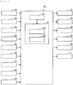
- Fig. 3 is a block diagram of an exemplary functional configuration of the controller 60.
- the motorcycle 100 includes: a trunk 1; a handlebar 2 that is held by the trunk 1 in a freely turnable manner; a front wheel 3 that is held by the trunk 1 in the freely turnable manner with the handlebar 2; a rear wheel 4 that is held by the trunk 1 in a freely rotatable manner; an engine 5; a transmission mechanism 6; and the brake system 10.
- the controller (ECU) 60 is provided in a hydraulic pressure control unit 50 of the brake system 10, which will be described later. As illustrated in Fig. 1 and Fig.
- the motorcycle 100 further includes: an inter-vehicular distance sensor 41, an input device 42, a front-wheel rotational frequency sensor 43, a rear-wheel rotational frequency sensor 44, a torque sensor 45, a crank angle sensor 46, a gear position sensor 47, a master-cylinder pressure sensor 48, and a wheel-cylinder pressure sensor 49.
- the engine 5 corresponds to an example of a drive source for the motorcycle 100, and can output drive power for driving a wheel (more specifically, the rear wheel 4 as a drive wheel) .
- the engine 5 is provided with: one or multiple cylinders in each of which a combustion chamber is formed; a fuel injector that injects fuel into the combustion chamber; and an ignition plug.
- a fuel injector that injects fuel into the combustion chamber
- an ignition plug When the fuel is injected from the fuel injector, air-fuel mixture containing air and the fuel is produced in the combustion chamber, and the air-fuel mixture is then ignited by the ignition plug and burned. Consequently, a piston provided in the cylinder reciprocates to cause a crankshaft to rotate.
- a throttle valve is provided in an intake pipe of the engine 5, and an intake air amount for the combustion chamber varies according to a throttle opening amount as an opening degree of the throttle valve.
- crankshaft of the engine 5 is connected to an input shaft of the transmission mechanism 6, and an output shaft of the transmission mechanism 6 is connected to the rear wheel 4.
- the power output from the engine 5 is transmitted to the transmission mechanism 6, is changed by the transmission mechanism 6, and is then transmitted to the rear wheel 4.
- the crankshaft of the engine 5 and the input shaft of the transmission mechanism 6 are connected via a clutch that connects/disconnects the power transmission.
- a gear stage of the transmission mechanism 6 is switched according to a shift lever operation by the driver in a disengaged state of the clutch.
- the brake system 10 includes: a first brake operation section 11; a front-wheel brake mechanism 12 that brakes the front wheel 3 in an interlocking manner with at least the first brake operation section 11; a second brake operation section 13; and a rear-wheel brake mechanism 14 that brakes the rear wheel 4 in an interlocking manner with at least the second brake operation section 13.
- the brake system 10 also includes the hydraulic pressure control unit 50, and a part of the front-wheel brake mechanism 12 and a part of the rear-wheel brake mechanism 14 are included in the hydraulic pressure control unit 50.
- the hydraulic pressure control unit 50 is a unit that has a function of controlling a braking force to be generated on the front wheel 3 by the front-wheel brake mechanism 12 and a braking force to be generated on the rear wheel 4 by the rear-wheel brake mechanism 14.
- the first brake operation section 11 is provided on the handlebar 2 and is operated by the driver's hand.
- the first brake operation section 11 is a brake lever, for example.
- the second brake operation section 13 is provided in a lower portion of the trunk 1 and is operated by the driver's foot.
- the second brake operation section 13 is a brake pedal, for example.
- Each of the front-wheel brake mechanism 12 and the rear-wheel brake mechanism 14 includes: a master cylinder 21 in which a piston (not illustrated) is installed; a reservoir 22 that is attached to the master cylinder 21; a brake caliper 23 that is held by the trunk 1 and has a brake pad (not illustrated) ; a wheel cylinder 24 that is provided in the brake caliper 23; a primary channel 25 through which a brake fluid in the master cylinder 21 flows into the wheel cylinder 24; a secondary channel 26 through which the brake fluid in the wheel cylinder 24 is released; and a supply channel 27 through which the brake fluid in the master cylinder 21 is supplied to the secondary channel 26.
- An inlet valve (EV) 31 is provided in the primary channel 25.
- the secondary channel 26 bypasses a portion of the primary channel 25 between the wheel cylinder 24 side and the master cylinder 21 side from the inlet valve 31.
- the secondary channel 26 is sequentially provided with an outlet valve (AV) 32, an accumulator 33, and a pump 34 from an upstream side.
- AV outlet valve
- AV accumulator
- pump 34 from an upstream side.
- AV outlet valve
- USV first valve
- the supply channel 27 communicates between the master cylinder 21 and a portion of the secondary channel 26 on a suction side of the pump 34.
- a second valve (HSV) 36 is provided in the supply channel 27.
- the inlet valve 31 is an electromagnetic valve that is opened in an unenergized state and closed in an energized state, for example.
- the outlet valve 32 is an electromagnetic valve that is closed in an unenergized state and opened in an energized state, for example.
- the first valve 35 is an electromagnetic valve that is opened in an unenergized state and is closed in an energized state, for example.
- the second valve 36 is an electromagnetic valve that is closed in an unenergized state and is opened in an energized state, for example.
- the hydraulic pressure control unit 50 includes: components such as the inlet valves 31, the outlet valves 32, the accumulators 33, the pumps 34, the first valves 35, and the second valves 36 used to control a brake hydraulic pressure; a base body 51 in which those components are provided and channels constituting the primary channels 25, the secondary channels 26, and the supply channels 27 are formed; and the controller 60.
- the base body 51 may be formed of one member or may be formed of multiple members. In the case where the base body 51 is formed of the multiple members, the components may separately be provided in the different members.
- the controller 60 controls operation of each of the components in the hydraulic pressure control unit 50. As a result, the braking force to be generated on the front wheel 3 by the front-wheel brake mechanism 12 and the braking force to be generated on the rear wheel 4 by the rear-wheel brake mechanism 14 are controlled.
- the controller 60 opens the inlet valves 31, closes the outlet valves 32, opens the first valves 35, and closes the second valves 36.
- the piston (not illustrated) in the master cylinder 21 is pressed to increase a hydraulic pressure of the brake fluid in the wheel cylinder 24, the brake pad (not illustrated) of the brake caliper 23 is then pressed against a rotor 3a of the front wheel 3, and the braking force is thereby generated on the front wheel 3.
- the piston (not illustrated) in the master cylinder 21 is pressed to increase the hydraulic pressure of the brake fluid in the wheel cylinder 24, the brake pad (not illustrated) of the brake caliper 23 is then pressed against a rotor 4a of the rear wheel 4, and the braking force is thereby generated on the rear wheel 4.
- the inter-vehicular distance sensor 41 detects a distance from the motorcycle 100 to a preceding vehicle.
- the inter-vehicular distance sensor 41 may detect another physical quantity that can substantially be converted to the distance from the motorcycle 100 to the preceding vehicle.
- the preceding vehicle means a vehicle ahead of the motorcycle 100 and may include, in addition to the nearest vehicle from the motorcycle 100 on the same lane as a travel lane of the motorcycle 100, a vehicle ahead of several vehicles in front of the motorcycle 100, a vehicle traveling on an adjacent lane to the travel lane of the motorcycle 100, and the like.
- the inter-vehicular distance sensor 41 selects the preceding vehicle as a detection target of the distance from the motorcycle 100.
- the adaptive cruise control which will be described later, is executed by using a detection result of the distance from the motorcycle 100 to the thus-selected preceding vehicle.
- the inter-vehicular distance sensor 41 for example, a camera that captures an image in front of the motorcycle 100 and a radar that can detect a distance from the motorcycle 100 to a target in front are used.
- the preceding vehicle is recognized by using the image captured by the camera. Then, by using the recognition result of the preceding vehicle and a detection result by the radar, the distance from the motorcycle 100 to the preceding vehicle can be detected.
- the inter-vehicular distance sensor 41 is provided in a front portion of the trunk 1, for example. Note that the configuration of the inter-vehicular distance sensor 41 is not limited to the above example, and a stereo camera may be used as the inter-vehicular distance sensor 41, for example.
- the input device 42 accepts a travel mode selection operation by the driver, and outputs information indicative of the travel mode selected by the driver.
- the controller 60 can execute the adaptive cruise control.
- the adaptive cruise control is control in which the motorcycle 100 is made to travel according to the distance from the motorcycle 100 to the preceding vehicle, motion of the motorcycle 100, and the driver's instruction.
- the driver can select, as one of the travel modes, a travel mode in which the adaptive cruise control is executed.
- a lever, a button, a touch screen, or the like is used as the input device 42.
- the input device 42 is provided on the handlebar 2, for example.
- the front-wheel rotational frequency sensor 43 detects a rotational frequency of the front wheel 3 and outputs a detection result.
- the front-wheel rotational frequency sensor 43 may detect another physical quantity that can substantially be converted to the rotational frequency of the front wheel 3.
- the front-wheel rotational frequency sensor 43 is provided on the front wheel 3.
- the rear-wheel rotational frequency sensor 44 detects a rotational frequency of the rear wheel 4 and outputs a detection result.
- the rear-wheel rotational frequency sensor 44 may detect another physical quantity that can substantially be converted to the rotational frequency of the rear wheel 4.
- the rear-wheel rotational frequency sensor 44 is provided on the rear wheel 4.
- the torque sensor 45 detects torque acting on the rear wheel 4 and outputs a detection result.
- the torque sensor 45 may detect another physical quantity that can substantially be converted to the torque acting on the rear wheel 4.
- the torque sensor 45 is provided on the rear wheel 4.
- the crank angle sensor 46 detects a crank angle of the engine 5 and outputs a detection result.
- the crank angle sensor 46 may detect another physical quantity that can substantially be converted to the crank angle of the engine 5.
- the crank angle sensor 46 is provided in the engine 5.
- the gear position sensor 47 detects at which gear stage the gear stage of the transmission mechanism 6 is set, and outputs a detection result.
- the gear position sensor 47 is provided in the transmission mechanism 6.
- the master-cylinder pressure sensor 48 detects the hydraulic pressure of the brake fluid in the master cylinder 21, and outputs a detection result.
- the master-cylinder pressure sensor 48 may detect another physical quantity that can substantially be converted to the hydraulic pressure of the brake fluid in the master cylinder 21.
- the master-cylinder pressure sensor 48 is provided in each of the front-wheel brake mechanism 12 and the rear-wheel brake mechanism 14.
- the wheel-cylinder pressure sensor 49 detects the hydraulic pressure of the brake fluid in the wheel cylinder 24, and outputs a detection result.
- the wheel-cylinder pressure sensor 49 may detect another physical quantity that can substantially be converted to the hydraulic pressure of the brake fluid in the wheel cylinder 24.
- the wheel-cylinder pressure sensor 49 is provided in each of the front-wheel brake mechanism 12 and the rear-wheel brake mechanism 14.
- the controller 60 controls travel of the motorcycle 100.
- the controller 60 is partially or entirely constructed of a microcomputer, a microprocessor unit, or the like.
- the controller 60 may partially or entirely be constructed of a member in which firmware or the like can be updated, or may partially or entirely be a program module or the like that is executed by a command from a CPU or the like, for example.
- the controller 60 may be provided as one unit or may be divided into multiple units, for example.
- the controller 60 includes an acquisition section 61 and a control section 62, for example.
- the acquisition section 61 acquires information that is output from each of the devices mounted on the motorcycle 100, and outputs the acquired information to the control section 62.
- the acquisition section 61 acquires the information output from the inter-vehicular distance sensor 41, the input device 42, the front-wheel rotational frequency sensor 43, the rear-wheel rotational frequency sensor 44, the torque sensor 45, the crank angle sensor 46, the gear position sensor 47, the master-cylinder pressure sensor 48, and the wheel-cylinder pressure sensor 49.
- the control section 62 controls operation of each of the devices mounted on the motorcycle 100, so as to control the drive power and the braking force exerted on the motorcycle 100.
- the control section 62 can execute the adaptive cruise control in which the motorcycle 100 is made to travel according to the distance from the motorcycle 100 to the preceding vehicle, the motion of the motorcycle 100, and the driver's instruction. More specifically, in the case where the driver selects the travel mode in which the adaptive cruise control is executed, the control section 62 executes the adaptive cruise control. Note that, in the case where the driver performs an accelerator operation or a brake operation during the adaptive cruise control, the control section 62 cancels the adaptive cruise control.
- the distance from the motorcycle 100 to the preceding vehicle is controlled to approximate a reference distance.
- the reference distance is set to a value with which the driver's safety can be secured.
- a speed of the motorcycle 100 is controlled at a set speed, which is set in advance.
- each of the acceleration and the deceleration of the motorcycle 100 is controlled to be equal to or lower than an upper limit value of such extent that does not worsen the driver's comfort.
- the control section 62 calculates a target value of the acceleration (hereinafter referred to as target acceleration) or a target value of the deceleration (hereinafter referred to as target deceleration) on the basis of a comparison result between the distance from the motorcycle 100 to the preceding vehicle and the reference distance and on the basis of a relative speed between the motorcycle 100 and the preceding vehicle. Then, based on a calculation result, the control section 62 controls the drive power and the braking force exerted on the motorcycle 100.
- target acceleration a target value of the acceleration
- target deceleration a target value of the deceleration
- the control section 62 calculates the target acceleration that corresponds to a difference between the distance from the motorcycle 100 to the preceding vehicle and the reference distance.
- the control section 62 calculates the target deceleration that corresponds to the difference between the distance from the motorcycle 100 to the preceding vehicle and the reference distance.
- the control section 62 includes a drive control section 62a and a brake control section 62b, for example.
- the drive control section 62a controls the drive power that is transmitted to the rear wheel 4 as the drive wheel during the adaptive cruise control. More specifically, during the adaptive cruise control, the drive control section 62a outputs a command to an engine control unit (not illustrated), which outputs a signal to control operation of each of the components of the engine 5 (the throttle valve, the fuel injector, the ignition plug, and the like) . In this way, the drive control section 62a controls operation of the engine 5. As a result, during the adaptive cruise control, the drive power, which is output from the engine 5 and transmitted to the rear wheel 4, is controlled.
- the operation of the engine 5 is controlled by the engine control unit such that the drive power is transmitted to the rear wheel 4 in response to the driver's accelerator operation.
- the drive control section 62a controls the operation of the engine 5 such that the drive power is transmitted to the rear wheel 4 without relying on the driver's accelerator operation. More specifically, during the adaptive cruise control, the drive control section 62a controls the operation of the engine 5 such that the acceleration of the motorcycle 100 becomes the target acceleration, which is calculated on the basis of the distance from the motorcycle 100 to the preceding vehicle and the relative speed between the motorcycle 100 and the preceding vehicle. In this way, the drive control section 62a controls the drive power transmitted to the rear wheel 4.
- the brake control section 62b controls the operation of each of the components of the hydraulic pressure control unit 50 in the brake system 10, so as to control the braking force generated on each of the wheels of the motorcycle 100.
- the brake control section 62b controls the operation of each of the components of the hydraulic pressure control unit 50 such that the braking force is generated on each of the wheels in response to the driver's brake operation.
- the brake control section 62b controls the operation of each of the components such that the braking force is generated on each of the wheels without relying on the driver's brake operation. More specifically, during the adaptive cruise control, the brake control section 62b controls the operation of each of the components of the hydraulic pressure control unit 50 such that the deceleration of the motorcycle 100 becomes the target deceleration, which is calculated on the basis of the distance from the motorcycle 100 to the preceding vehicle and the relative speed between the motorcycle 100 and the preceding vehicle. In this way, the brake control section 62b controls the braking force generated on each of the wheels.
- the brake control section 62b brings the motorcycle 100 into a state where the inlet valves 31 are opened, the outlet valves 32 are closed, the first valves 35 are closed, and the second valves 36 are opened, and drives the pumps 34 in such a state, so as to increase the hydraulic pressure of the brake fluid in each of the wheel cylinders 24 and generate the braking force on each of the wheels.
- the brake control section 62b regulates the hydraulic pressure of the brake fluid in each of the wheel cylinders 24 by controlling an opening amount of the first valve 35, for example. In this way, the brake control section 62b can control the braking force generated on each of the wheels.
- the brake control section 62b separately controls operation of each of the front-wheel brake mechanism 12 and the rear-wheel brake mechanism 14, so as to separately control the hydraulic pressure of the brake fluid in the wheel cylinder 24 of each of the front-wheel brake mechanism 12 and the rear-wheel brake mechanism 14. In this way, the brake control section 62b can control braking force distribution between the front and rear wheels (that is, distribution of the braking force generated on the front wheel 3 and the braking force generated on the rear wheel 4).
- the brake control section 62b controls the braking force distribution between the front and rear wheels such that a total of target values of the braking forces generated on the wheels becomes a requested braking force (that is, the braking force that is requested at the time of braking during the adaptive cruise control) corresponding to the target deceleration.
- the requested braking force is specifically the required braking force to bring the deceleration of the motorcycle 100 to the target deceleration, which is calculated on the basis of the distance from the motorcycle 100 to the preceding vehicle and the relative speed between the motorcycle 100 and the preceding vehicle.
- the brake control section 62b may execute the anti-lock brake control.
- the anti-lock brake control is control for regulating the braking force of the wheel, which is locked or possibly locked, to such a magnitude that locking of the wheel can be avoided.
- the brake control section 62b brings the motorcycle 100 into a state where the inlet valves 31 are closed, the outlet valves 32 are opened, the first valves 35 are opened, and the second valves 36 are closed, and drives the pumps 34 in such a state, so as to reduce the hydraulic pressure of the brake fluid in each of the wheel cylinders 24 and reduce the braking force generated on each of the wheels.
- the brake control section 62b closes both of the inlet valves 31 and the outlet valves 32 from the above state, for example. In this way, the brake control section 62b can keep the hydraulic pressure of the brake fluid in each of the wheel cylinders 24 and thus can keep the braking force generated on the each of wheels.
- the brake control section 62b opens the inlet valves 31 and closes the outlet valves 32 from the above state, for example. In this way, the brake control section 62b can increase the hydraulic pressure of the brake fluid in each of the wheel cylinders 24 and thus can increase the braking force generated on each of the wheels.
- the control section 62 can execute the adaptive cruise control.
- the control section 62 controls the braking force generated on each of the wheels such that the reference braking force is generated on the rear wheel 4 at a time point at which the rear wheel 4 starts being driven due to the transmission of the drive power output from the engine 5 to the rear wheel 4. In this way, the driver's comfort can be secured during the adaptive cruise control for the motorcycle 100.
- a detailed description will be made below on such processing that is related to switching from the decelerated state to the accelerated state during the adaptive cruise control and is executed by the controller 60.
- the above decelerated state may include a state where the braking force is generated on each of the wheels due to action of engine brake, in addition to the state where the braking force is generated on each of the wheels by controlling the operation of each of the components of the hydraulic pressure control unit 50 in the brake system 10.
- the drive control section 62a controls the operation of the engine 5 via the engine control unit.
- the drive control section 62a may output a signal for controlling the operation of each of the components of the engine 5, so as to directly control the operation of each of the components of the engine 5.
- the drive control section 62a controls the operation of the engine 5 in the normal time in a similar manner to the operation of the engine 5 during the adaptive cruise control.
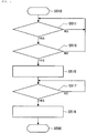
- Fig. 4 is a flowchart of an exemplary processing procedure that is executed by the controller 60. More specifically, a control flow illustrated in Fig. 4 corresponds to a processing procedure that is related to switching from the decelerated state to the accelerated state during the adaptive cruise control and is executed by the control section 62 of the controller 60, and is repeatedly executed during the adaptive cruise control. In addition, step S510 and step S590 in Fig. 4 respectively correspond to initiation and termination of the control flow illustrated in Fig. 4 .
- step S511 the control section 62 determines whether the wheels of the motorcycle 100 are braked. If it is determined that the wheels of the motorcycle 100 are braked (step S511/YES), the processing proceeds to step S513. On the other hand, if it is determined that the wheels of the motorcycle 100 are not braked (step S511/NO), the determination processing in step S511 is repeated.
- step S513 determines whether the engine 5 starts outputting the drive power. If it is determined that the engine 5 starts outputting the drive power (step S513/YES), the processing proceeds to step S515. On the other hand, if it is determined that the engine 5 does not start outputting the drive power (step S513/NO), the processing returns to the determination processing in step S511.
- control section 62 determines that the engine 5 starts outputting the drive power in the case where a request to start accelerating the motorcycle 100 is generated and where a command that causes the engine 5 to start outputting the drive power is output to the engine control unit.
- control section 62 may determine whether the engine 5 starts outputting the drive power by a different method from the above.
- control section 62 may determine whether the engine 5 starts outputting the drive power on the basis of a temporal change in a parameter such as an engine speed, a fuel injection amount, or the like.
- step S515 the brake control section 62b makes the brake system 10 start applying the reference braking force to the rear wheel 4.
- the reference braking force is set to the braking force of such extent that can maintain acceleration performance of the motorcycle 100 to desired performance while alleviating a shock generated at the time point at which the rear wheel 4 starts being driven.
- the brake control section 62b stops the application of the braking force to the front wheel 3, and then starts the application of the reference braking force to the rear wheel 4.
- the braking force may temporarily be generated on the front wheel 3 after a time point at which it is determined that the engine 5 starts outputting the drive power.
- the brake control section 62b continuously generates the reference braking force on the rear wheel 4.
- the state where the reference braking force is generated on the rear wheel 4 continues to the time point at which the rear wheel 4 starts being driven due to the transmission of the drive power output from the engine 5 to the rear wheel 4.
- the reference braking force is generated on the rear wheel 4 at the time point at which the rear wheel 4 starts being driven.
- the drive power output from the engine 5 is transmitted to the rear wheel 4 via a power transmission system including the transmission mechanism 6.
- the shock occurs due to backlash of a gear in the power transmission system or the like, for example.
- the controller 60 causes the generation of the reference braking force on the rear wheel 4.
- the brake control section 62b appropriately sets the above reference braking force.
- the brake control section 62b preferably controls the reference braking force to such a magnitude that corresponds to a gear ratio of the transmission mechanism 6.
- the brake control section 62b preferably controls the reference braking force to such a magnitude that corresponds to the drive power output from the engine 5.
- the brake control section 62b may control the reference braking force on the basis of the multiple parameters (for example, both of the gear ratio of the transmission mechanism 6 and the drive power output from the engine 5).
- step S517 the control section 62 determines whether the rear wheel 4 starts being driven due to the transmission of the drive power output from the engine 5 to the rear wheel 4. If it is determined that the rear wheel 4 starts being driven (step S517/YES), the processing proceeds to step S519. On the other hand, if it is determined that the rear wheel 4 does not start being driven (step S517/NO), the determination processing in step S517 is repeated.
- control section 62 determines that the rear wheel 4 starts being driven in the case where the torque acting on the rear wheel 4 starts being increased. Such a determination can be made by using the detection result by the torque sensor 45.
- control section 62 determines that the rear wheel 4 starts being driven in the case where rotational acceleration of the rear wheel 4 starts being increased. Such a determination can be made by using the detection result by the rear-wheel rotational frequency sensor 44.
- step S519 the brake control section 62b makes the brake system 10 stop applying the reference braking force to the rear wheel 4.
- the brake control section 62b stops the generation of the reference braking force on the rear wheel 4 in the case where it is determined that the rear wheel 4 starts being driven.
- the control section 62 controls the braking force generated on each of the wheels such that the reference braking force is generated on the rear wheel 4 at the time point at which the rear wheel 4 starts being driven due to the transmission of the drive power output from the engine 5 to the rear wheel 4.
- the above description has been made on the example in which the reference braking force is generated on the rear wheel 4 at the time point at which it is determined that the engine 5 starts outputting the drive power.
- the time point at which the reference braking force is generated on the rear wheel 4 (that is, the time point at which the reference braking force starts being applied to the rear wheel 4) is not limited to the above example.
- the brake control section 62b may cause the generation of the reference braking force on the rear wheel 4 at a time point corresponding to the time point at which the engine 5 starts outputting the drive power.
- the brake control section 62b may cause the generation of the reference braking force on the rear wheel 4 at a time point later than the time point, at which the engine 5 starts outputting the drive power, by first reference duration.
- the first reference duration is set to shorter duration than average duration that is assumed as duration from the time point at which the engine 5 starts outputting the drive power to the time point at which the rear wheel 4 starts being driven.
- time point at which the engine 5 starts outputting the drive power for example, the time point at which the engine 5 starts outputting the drive power may be used, or a time point at which duration corresponding to a delay in communication between the devices, responsiveness of each of the components in the engine 5, or the like is added to the above time point may be used.
- the brake control section 62b may estimate the time point at which the rear wheel 4 starts being driven, and may cause the generation of the reference braking force on the rear wheel 4 at a time point corresponding to the estimated time point. For example, the brake control section 62b may cause the generation of the reference braking force on the rear wheel 4 at a time point prior to the time point, which is estimated as the time point at which the rear wheel 4 starts being driven, by second reference duration.
- the second reference duration is set to such duration that the reliable generation of the reference braking force on the rear wheel 4 is maintained at the time point at which the rear wheel 4 starts being driven.
- the brake control section 62b can estimate the time point at which the rear wheel 4 starts being driven by estimating the duration that takes until the rear wheel 4 starts being driven on the basis of the crank angle of the engine 5, for example. Such estimation can be made by using the detection result by the crank angle sensor 46.
- the time point at which the generation of the reference braking force on the rear wheel 4 is stopped (that is, the time point at which the reference braking force stops being applied to the rear wheel 4) is not limited to the above example.
- the brake control section 62b may estimate the time point at which the rear wheel 4 starts being driven, and may stop the generation of the reference braking force on the rear wheel 4 at a time point corresponding to the estimated time point. For example, the brake control section 62b may stop the generation of the reference braking force on the rear wheel 4 at a time point later than the time point, which is estimated as the time point at which the rear wheel 4 starts being driven, by third reference duration.
- the third reference duration is set to such duration that the state where the reference braking force is generated on the rear wheel 4 can promptly be canceled after the time point at which the rear wheel 4 starts being driven elapses.
- the control section 62 of the controller 60 controls the braking force generated on the at least one of the wheels such that the reference braking force is generated on the rear wheel 4 at the time point at which the rear wheel 4 starts being driven due to the transmission of the drive power output from the engine 5 to the rear wheel 4. In this way, it is possible to alleviate the shock that occurs due to the transmission of the drive power at the time point of starting driving of the rear wheel 4. Thus, the driver's comfort can be secured during the adaptive cruise control for the motorcycle 100.
- the control section 62 controls the reference braking force on the basis of the gear ratio of the transmission mechanism 6 in the motorcycle 100.
- a magnitude of the drive power transmitted to the rear wheel 4 varies according to the gear ratio of the transmission mechanism 6. More specifically, in the case where the constant drive power is output from the engine 5, the magnitude of the drive power is increased with the higher gear ratio.
- the reference braking force can appropriately be controlled according to the magnitude of the drive power that is transmitted to the rear wheel 4 at the time point at which the rear wheel 4 starts being driven.
- the control section 62 controls the reference braking force on the basis of the drive power output from the engine 5.
- the magnitude of the drive power transmitted to the rear wheel 4 varies according to the drive power output from the engine 5.
- the reference braking force can appropriately be controlled according to the magnitude of the drive power that is transmitted to the rear wheel 4 at the time point at which the rear wheel 4 starts being driven.
- the control section 62 causes the continuous generation of the reference braking force on the rear wheel 4 at the time point, at which it is determined that the engine 5 starts outputting the drive power, onward, and then stops the generation of the reference braking force on the rear wheel 4 in the case where it is determined that the rear wheel 4 starts being driven.
- the control section 62 causes the continuous generation of the reference braking force on the rear wheel 4 at the time point, at which it is determined that the engine 5 starts outputting the drive power, onward, and then stops the generation of the reference braking force on the rear wheel 4 in the case where it is determined that the rear wheel 4 starts being driven.
- the control section 62 causes the generation of the reference braking force on the rear wheel 4 at the time point corresponding to the time point at which the engine 5 starts outputting the drive power.
- the reliable generation of the reference braking force on the rear wheel 4 at the time point at which the rear wheel 4 starts being driven is appropriately maintained, deterioration of the acceleration performance of the motorcycle 100, which is caused by the generation of the reference braking force before the time point at which the rear wheel 4 starts being driven, can be suppressed.
- the control section 62 estimates the time point at which the rear wheel 4 starts being driven, and causes the generation of the reference braking force on the rear wheel 4 at the time point corresponding to the estimated time point.
- the reliable generation of the reference braking force on the rear wheel 4 at the time point at which the rear wheel 4 starts being driven is appropriately maintained, the deterioration of the acceleration performance of the motorcycle, which is caused by the generation of the reference braking force before the time point at which the rear wheel 4 starts being driven, can be suppressed.
- the control section 62 estimates the time point at which the rear wheel 4 starts being driven, and stops the generation of the reference braking force on the rear wheel 4 at the time point corresponding to the estimated time point. In this way, it is possible to promptly cancel the state where the reference braking force is generated on the rear wheel 4 after the time point at which the rear wheel 4 starts being driven elapses. Therefore, it is possible to further appropriately secure the acceleration performance of the motorcycle 100.
- the present invention is not limited to each of the embodiments that have been described. For example, all or parts of the embodiments may be combined, or only a part of each of the embodiments may be implemented.
Landscapes
- Engineering & Computer Science (AREA)
- Mechanical Engineering (AREA)
- Transportation (AREA)
- Chemical & Material Sciences (AREA)
- Combustion & Propulsion (AREA)
- Automation & Control Theory (AREA)
- General Engineering & Computer Science (AREA)
- Physics & Mathematics (AREA)
- Fluid Mechanics (AREA)
- Regulating Braking Force (AREA)
- Control Of Driving Devices And Active Controlling Of Vehicle (AREA)
- Control Of Vehicle Engines Or Engines For Specific Uses (AREA)
Abstract
Description
- The present disclosure relates to a controller and a control method capable of securing a driver's comfort during adaptive cruise control for a straddle-type vehicle.
- As a conventional technique relating to a straddle-type vehicle, a technique of assisting with a driver's operation is available.
- For example, a driver assistance system is disclosed in
PTL 1. Based on information detected by a sensor that detects an obstacle present in a travel direction or substantially in the travel direction, the driver assistance system warns a motorcycle driver that the motorcycle inappropriately approaches the obstacle. - PTL 1:
JP-A-2009-116882 - By the way, as a technique of assisting with the driver's operation, it is considered to apply adaptive cruise control, in which a vehicle is made to travel according to a distance from the vehicle to a preceding vehicle, motion of the vehicle, and the driver's instruction, to a straddle-type vehicle such as the motorcycle. In the adaptive cruise control for the straddle-type vehicle, the straddle-type vehicle is automatically accelerated or decelerated without relying on an acceleration or deceleration operation by the driver. Here, the straddle-type vehicle is accelerated by driving a drive wheel using drive power output from a drive source. However, at a time point at which the drive wheel starts being driven due to transmission of the drive power output from the drive source to the drive wheel, a shock occurs due to backlash of a gear or the like. During the adaptive cruise control, as described above, the straddle-type vehicle is automatically accelerated. Thus, the shock, which occurs at the time point at which the drive wheel starts being driven, is likely to become a cause of worsening the driver's comfort.
- The present invention has been made in view of the above-described problem, and therefore obtains a controller and a control method capable of securing a driver's comfort during adaptive cruise control for a straddle-type vehicle. Solution to Problem
- A controller according to the present invention is a controller that controls travel of a straddle-type vehicle, and includes a control section capable of executing adaptive cruise control in which the straddle-type vehicle is made to travel according to a distance from the straddle-type vehicle to a preceding vehicle, motion of the straddle-type vehicle, and a driver's instruction. During the adaptive cruise control, when a state where a braking force is generated on at least one of wheels of the straddle-type vehicle is switched to a state where a drive wheel is driven using drive power output from a drive source of the straddle-type vehicle, the control section controls the braking force generated on the at least one of the wheels such that a reference braking force is generated on the drive wheel at a time point at which the drive wheel starts being driven due to transmission of the drive power output from the drive source to the drive wheel.
- A control method according to the present invention is a control method for controlling travel of a straddle-type vehicle, and includes controlling a braking force generated on at least one of wheels by a controller such that a reference braking force is generated on a drive wheel at a time point at which the drive wheel starts being driven due to transmission of drive power output from a drive source to the drive wheel when a state where the braking force is generated on the at least one of the wheels of the straddle-type vehicle is switched to a state where the drive wheel is driven using the drive power output from the drive source of the straddle-type vehicle during adaptive cruise control in which the straddle-type vehicle is made to travel according to a distance from the straddle-type vehicle to a preceding vehicle, motion of the straddle-type vehicle, and a driver's instruction.
- In the controller and the control method according to the present invention, during the adaptive cruise control in which the straddle-type vehicle is made to travel according to the distance from the straddle-type vehicle to the preceding vehicle, the motion of the straddle-type vehicle, and the driver's instruction, when the state where the braking force is generated on at least one of the wheels of the straddle-type vehicle is switched to the state where the drive wheel is driven using the drive power output from the drive source of the straddle-type vehicle, the braking force generated on the at least of the wheels is controlled such that the reference braking force is generated on the drive wheel at the time point at which the drive wheel starts being driven due to the transmission of the drive power output from the drive source to the drive wheel. Thus, it is possible to alleviate a shock that occurs due to the transmission of the drive power at the time point at which the drive wheel starts being driven. Therefore, the driver's comfort can be secured during the adaptive cruise control for the straddle-type vehicle.
-
-
Fig. 1 is a schematic view of a configuration of a motorcycle on which a controller according to an embodiment of the present invention is mounted. -
Fig. 2 is a schematic view of a configuration of a brake system according to the embodiment of the present invention. -
Fig. 3 is a block diagram of an exemplary functional configuration of the controller according to the embodiment of the present invention. -
Fig. 4 is a flowchart of an exemplary processing procedure that is executed by the controller according to the embodiment of the present invention. - A description will hereinafter be made on a controller according to the present invention with reference to the drawings. Hereinafter, a description will be made on the controller used for a two-wheeled motorcycle. However, the controller according to the present invention may be used for a straddle-type vehicle other than the two-wheeled motorcycle (for example, a three-wheeled motorcycle, an all-terrain vehicle, a bicycle, or the like). The straddle-type vehicle means a vehicle that a driver straddles. In addition, a description will hereinafter be made on a case where an engine is mounted as a drive source capable of outputting drive power for driving a wheel of the motorcycle. However, as the drive source of the motorcycle, a drive source other than the engine (for example, a motor) may be mounted, or multiple drive sources may be mounted. Furthermore, a description will hereinafter be made on a case where the motorcycle is a rear-wheel drive vehicle. However, the motorcycle may be a front-wheel-drive vehicle, and a reference braking force may be generated on a front wheel.
- A configuration, operation, and the like, which will be described below, merely constitute one example. The controller and the control method according to the present invention are not limited to a case with such a configuration, such operation, and the like.
- The same or similar description will appropriately be simplified or will not be made below. In the drawings, the same or similar members or portions will not be denoted by a reference sign or will be denoted by the same reference sign. In addition, a detailed structure will appropriately be illustrated in a simplified manner or will not be illustrated.
- A description will be made on a configuration of a
motorcycle 100 on which acontroller 60 according to an embodiment of the present invention is mounted with reference toFig. 1 to Fig. 3 . -
Fig. 1 is a schematic view of the configuration of themotorcycle 100 on which thecontroller 60 is mounted.Fig. 2 is a schematic diagram of a configuration of abrake system 10.Fig. 3 is a block diagram of an exemplary functional configuration of thecontroller 60. - As illustrated in
Fig. 1 , themotorcycle 100 includes: atrunk 1; ahandlebar 2 that is held by thetrunk 1 in a freely turnable manner; afront wheel 3 that is held by thetrunk 1 in the freely turnable manner with thehandlebar 2; arear wheel 4 that is held by thetrunk 1 in a freely rotatable manner; anengine 5; atransmission mechanism 6; and thebrake system 10. In this embodiment, the controller (ECU) 60 is provided in a hydraulicpressure control unit 50 of thebrake system 10, which will be described later. As illustrated inFig. 1 andFig. 2 , themotorcycle 100 further includes: aninter-vehicular distance sensor 41, aninput device 42, a front-wheelrotational frequency sensor 43, a rear-wheelrotational frequency sensor 44, atorque sensor 45, acrank angle sensor 46, agear position sensor 47, a master-cylinder pressure sensor 48, and a wheel-cylinder pressure sensor 49. - The
engine 5 corresponds to an example of a drive source for themotorcycle 100, and can output drive power for driving a wheel (more specifically, therear wheel 4 as a drive wheel) . For example, theengine 5 is provided with: one or multiple cylinders in each of which a combustion chamber is formed; a fuel injector that injects fuel into the combustion chamber; and an ignition plug. When the fuel is injected from the fuel injector, air-fuel mixture containing air and the fuel is produced in the combustion chamber, and the air-fuel mixture is then ignited by the ignition plug and burned. Consequently, a piston provided in the cylinder reciprocates to cause a crankshaft to rotate. In addition, a throttle valve is provided in an intake pipe of theengine 5, and an intake air amount for the combustion chamber varies according to a throttle opening amount as an opening degree of the throttle valve. - The crankshaft of the
engine 5 is connected to an input shaft of thetransmission mechanism 6, and an output shaft of thetransmission mechanism 6 is connected to therear wheel 4. Thus, the power output from theengine 5 is transmitted to thetransmission mechanism 6, is changed by thetransmission mechanism 6, and is then transmitted to therear wheel 4. In detail, the crankshaft of theengine 5 and the input shaft of thetransmission mechanism 6 are connected via a clutch that connects/disconnects the power transmission. When the clutch is operated, a gear stage of thetransmission mechanism 6 is switched according to a shift lever operation by the driver in a disengaged state of the clutch. - As illustrated in
Fig. 1 andFig. 2 , thebrake system 10 includes: a firstbrake operation section 11; a front-wheel brake mechanism 12 that brakes thefront wheel 3 in an interlocking manner with at least the firstbrake operation section 11; a secondbrake operation section 13; and a rear-wheel brake mechanism 14 that brakes therear wheel 4 in an interlocking manner with at least the secondbrake operation section 13. Thebrake system 10 also includes the hydraulicpressure control unit 50, and a part of the front-wheel brake mechanism 12 and a part of the rear-wheel brake mechanism 14 are included in the hydraulicpressure control unit 50. The hydraulicpressure control unit 50 is a unit that has a function of controlling a braking force to be generated on thefront wheel 3 by the front-wheel brake mechanism 12 and a braking force to be generated on therear wheel 4 by the rear-wheel brake mechanism 14. - The first
brake operation section 11 is provided on thehandlebar 2 and is operated by the driver's hand. The firstbrake operation section 11 is a brake lever, for example. The secondbrake operation section 13 is provided in a lower portion of thetrunk 1 and is operated by the driver's foot. The secondbrake operation section 13 is a brake pedal, for example. - Each of the front-
wheel brake mechanism 12 and the rear-wheel brake mechanism 14 includes: amaster cylinder 21 in which a piston (not illustrated) is installed; areservoir 22 that is attached to themaster cylinder 21; abrake caliper 23 that is held by thetrunk 1 and has a brake pad (not illustrated) ; awheel cylinder 24 that is provided in thebrake caliper 23; aprimary channel 25 through which a brake fluid in themaster cylinder 21 flows into thewheel cylinder 24; asecondary channel 26 through which the brake fluid in thewheel cylinder 24 is released; and asupply channel 27 through which the brake fluid in themaster cylinder 21 is supplied to thesecondary channel 26. - An inlet valve (EV) 31 is provided in the
primary channel 25. Thesecondary channel 26 bypasses a portion of theprimary channel 25 between thewheel cylinder 24 side and themaster cylinder 21 side from theinlet valve 31. Thesecondary channel 26 is sequentially provided with an outlet valve (AV) 32, anaccumulator 33, and apump 34 from an upstream side. Between an end of theprimary channel 25 on themaster cylinder 21 side and a portion of theprimary channel 25 to which a downstream end of thesecondary channel 26 is connected, a first valve (USV) 35 is provided. Thesupply channel 27 communicates between themaster cylinder 21 and a portion of thesecondary channel 26 on a suction side of thepump 34. A second valve (HSV) 36 is provided in thesupply channel 27. - The
inlet valve 31 is an electromagnetic valve that is opened in an unenergized state and closed in an energized state, for example. Theoutlet valve 32 is an electromagnetic valve that is closed in an unenergized state and opened in an energized state, for example. Thefirst valve 35 is an electromagnetic valve that is opened in an unenergized state and is closed in an energized state, for example. Thesecond valve 36 is an electromagnetic valve that is closed in an unenergized state and is opened in an energized state, for example. - The hydraulic
pressure control unit 50 includes: components such as theinlet valves 31, theoutlet valves 32, theaccumulators 33, thepumps 34, thefirst valves 35, and thesecond valves 36 used to control a brake hydraulic pressure; abase body 51 in which those components are provided and channels constituting theprimary channels 25, thesecondary channels 26, and thesupply channels 27 are formed; and thecontroller 60. - The
base body 51 may be formed of one member or may be formed of multiple members. In the case where thebase body 51 is formed of the multiple members, the components may separately be provided in the different members. - The
controller 60 controls operation of each of the components in the hydraulicpressure control unit 50. As a result, the braking force to be generated on thefront wheel 3 by the front-wheel brake mechanism 12 and the braking force to be generated on therear wheel 4 by the rear-wheel brake mechanism 14 are controlled. - For example, in a normal time (that is, when none of adaptive cruise control and anti-lock brake control, which will be described later, is executed), the
controller 60 opens theinlet valves 31, closes theoutlet valves 32, opens thefirst valves 35, and closes thesecond valves 36. When the firstbrake operation section 11 is operated in such a state, in the front-wheel brake mechanism 12, the piston (not illustrated) in themaster cylinder 21 is pressed to increase a hydraulic pressure of the brake fluid in thewheel cylinder 24, the brake pad (not illustrated) of thebrake caliper 23 is then pressed against arotor 3a of thefront wheel 3, and the braking force is thereby generated on thefront wheel 3. Meanwhile, when the secondbrake operation section 13 is operated, in the rear-wheel brake mechanism 14, the piston (not illustrated) in themaster cylinder 21 is pressed to increase the hydraulic pressure of the brake fluid in thewheel cylinder 24, the brake pad (not illustrated) of thebrake caliper 23 is then pressed against arotor 4a of therear wheel 4, and the braking force is thereby generated on therear wheel 4. - The
inter-vehicular distance sensor 41 detects a distance from themotorcycle 100 to a preceding vehicle. Theinter-vehicular distance sensor 41 may detect another physical quantity that can substantially be converted to the distance from themotorcycle 100 to the preceding vehicle. Here, the preceding vehicle means a vehicle ahead of themotorcycle 100 and may include, in addition to the nearest vehicle from themotorcycle 100 on the same lane as a travel lane of themotorcycle 100, a vehicle ahead of several vehicles in front of themotorcycle 100, a vehicle traveling on an adjacent lane to the travel lane of themotorcycle 100, and the like. For example, in the case where the multiple vehicles exist ahead of themotorcycle 100, based on a track, which is estimated as a travel track of themotorcycle 100, and behavior of each of the multiple vehicles, theinter-vehicular distance sensor 41 selects the preceding vehicle as a detection target of the distance from themotorcycle 100. In this case, the adaptive cruise control, which will be described later, is executed by using a detection result of the distance from themotorcycle 100 to the thus-selected preceding vehicle. - As the
inter-vehicular distance sensor 41, for example, a camera that captures an image in front of themotorcycle 100 and a radar that can detect a distance from themotorcycle 100 to a target in front are used. In such a case, for example, the preceding vehicle is recognized by using the image captured by the camera. Then, by using the recognition result of the preceding vehicle and a detection result by the radar, the distance from themotorcycle 100 to the preceding vehicle can be detected. Theinter-vehicular distance sensor 41 is provided in a front portion of thetrunk 1, for example. Note that the configuration of theinter-vehicular distance sensor 41 is not limited to the above example, and a stereo camera may be used as theinter-vehicular distance sensor 41, for example. - The
input device 42 accepts a travel mode selection operation by the driver, and outputs information indicative of the travel mode selected by the driver. As will be described later, in themotorcycle 100, thecontroller 60 can execute the adaptive cruise control. The adaptive cruise control is control in which themotorcycle 100 is made to travel according to the distance from themotorcycle 100 to the preceding vehicle, motion of themotorcycle 100, and the driver's instruction. By using theinput device 42, the driver can select, as one of the travel modes, a travel mode in which the adaptive cruise control is executed. For example, as theinput device 42, a lever, a button, a touch screen, or the like is used. Theinput device 42 is provided on thehandlebar 2, for example. - The front-wheel
rotational frequency sensor 43 detects a rotational frequency of thefront wheel 3 and outputs a detection result. The front-wheelrotational frequency sensor 43 may detect another physical quantity that can substantially be converted to the rotational frequency of thefront wheel 3. The front-wheelrotational frequency sensor 43 is provided on thefront wheel 3. - The rear-wheel
rotational frequency sensor 44 detects a rotational frequency of therear wheel 4 and outputs a detection result. The rear-wheelrotational frequency sensor 44 may detect another physical quantity that can substantially be converted to the rotational frequency of therear wheel 4. The rear-wheelrotational frequency sensor 44 is provided on therear wheel 4. - The
torque sensor 45 detects torque acting on therear wheel 4 and outputs a detection result. Thetorque sensor 45 may detect another physical quantity that can substantially be converted to the torque acting on therear wheel 4. Thetorque sensor 45 is provided on therear wheel 4. - The
crank angle sensor 46 detects a crank angle of theengine 5 and outputs a detection result. Thecrank angle sensor 46 may detect another physical quantity that can substantially be converted to the crank angle of theengine 5. Thecrank angle sensor 46 is provided in theengine 5. - The
gear position sensor 47 detects at which gear stage the gear stage of thetransmission mechanism 6 is set, and outputs a detection result. Thegear position sensor 47 is provided in thetransmission mechanism 6. - The master-
cylinder pressure sensor 48 detects the hydraulic pressure of the brake fluid in themaster cylinder 21, and outputs a detection result. The master-cylinder pressure sensor 48 may detect another physical quantity that can substantially be converted to the hydraulic pressure of the brake fluid in themaster cylinder 21. The master-cylinder pressure sensor 48 is provided in each of the front-wheel brake mechanism 12 and the rear-wheel brake mechanism 14. - The wheel-
cylinder pressure sensor 49 detects the hydraulic pressure of the brake fluid in thewheel cylinder 24, and outputs a detection result. The wheel-cylinder pressure sensor 49 may detect another physical quantity that can substantially be converted to the hydraulic pressure of the brake fluid in thewheel cylinder 24. The wheel-cylinder pressure sensor 49 is provided in each of the front-wheel brake mechanism 12 and the rear-wheel brake mechanism 14. - The
controller 60 controls travel of themotorcycle 100. - For example, the
controller 60 is partially or entirely constructed of a microcomputer, a microprocessor unit, or the like. Alternatively, thecontroller 60 may partially or entirely be constructed of a member in which firmware or the like can be updated, or may partially or entirely be a program module or the like that is executed by a command from a CPU or the like, for example. Thecontroller 60 may be provided as one unit or may be divided into multiple units, for example. - As illustrated in
Fig. 3 , thecontroller 60 includes anacquisition section 61 and acontrol section 62, for example. - The
acquisition section 61 acquires information that is output from each of the devices mounted on themotorcycle 100, and outputs the acquired information to thecontrol section 62. For example, theacquisition section 61 acquires the information output from theinter-vehicular distance sensor 41, theinput device 42, the front-wheelrotational frequency sensor 43, the rear-wheelrotational frequency sensor 44, thetorque sensor 45, thecrank angle sensor 46, thegear position sensor 47, the master-cylinder pressure sensor 48, and the wheel-cylinder pressure sensor 49. - The
control section 62 controls operation of each of the devices mounted on themotorcycle 100, so as to control the drive power and the braking force exerted on themotorcycle 100. - Here, by controlling the operation of each of the devices mounted on the
motorcycle 100, thecontrol section 62 can execute the adaptive cruise control in which themotorcycle 100 is made to travel according to the distance from themotorcycle 100 to the preceding vehicle, the motion of themotorcycle 100, and the driver's instruction. More specifically, in the case where the driver selects the travel mode in which the adaptive cruise control is executed, thecontrol section 62 executes the adaptive cruise control. Note that, in the case where the driver performs an accelerator operation or a brake operation during the adaptive cruise control, thecontrol section 62 cancels the adaptive cruise control. - In the adaptive cruise control, the distance from the
motorcycle 100 to the preceding vehicle is controlled to approximate a reference distance. As the distance from themotorcycle 100 to the preceding vehicle, the reference distance is set to a value with which the driver's safety can be secured. In the case where no preceding vehicle is recognized, a speed of themotorcycle 100 is controlled at a set speed, which is set in advance. In addition, in the adaptive cruise control, each of the acceleration and the deceleration of themotorcycle 100 is controlled to be equal to or lower than an upper limit value of such extent that does not worsen the driver's comfort. - More specifically, during the adaptive cruise control, the
control section 62 calculates a target value of the acceleration (hereinafter referred to as target acceleration) or a target value of the deceleration (hereinafter referred to as target deceleration) on the basis of a comparison result between the distance from themotorcycle 100 to the preceding vehicle and the reference distance and on the basis of a relative speed between themotorcycle 100 and the preceding vehicle. Then, based on a calculation result, thecontrol section 62 controls the drive power and the braking force exerted on themotorcycle 100. - For example, in the case where the distance from the
motorcycle 100 to the preceding vehicle is longer than the reference distance, thecontrol section 62 calculates the target acceleration that corresponds to a difference between the distance from themotorcycle 100 to the preceding vehicle and the reference distance. On the other hand, in the case where the distance from themotorcycle 100 to the preceding vehicle is shorter than the reference distance, thecontrol section 62 calculates the target deceleration that corresponds to the difference between the distance from themotorcycle 100 to the preceding vehicle and the reference distance. - The
control section 62 includes adrive control section 62a and abrake control section 62b, for example. - The
drive control section 62a controls the drive power that is transmitted to therear wheel 4 as the drive wheel during the adaptive cruise control. More specifically, during the adaptive cruise control, thedrive control section 62a outputs a command to an engine control unit (not illustrated), which outputs a signal to control operation of each of the components of the engine 5 (the throttle valve, the fuel injector, the ignition plug, and the like) . In this way, thedrive control section 62a controls operation of theengine 5. As a result, during the adaptive cruise control, the drive power, which is output from theengine 5 and transmitted to therear wheel 4, is controlled. - In the normal time, the operation of the
engine 5 is controlled by the engine control unit such that the drive power is transmitted to therear wheel 4 in response to the driver's accelerator operation. - Meanwhile, during the adaptive cruise control, the
drive control section 62a controls the operation of theengine 5 such that the drive power is transmitted to therear wheel 4 without relying on the driver's accelerator operation. More specifically, during the adaptive cruise control, thedrive control section 62a controls the operation of theengine 5 such that the acceleration of themotorcycle 100 becomes the target acceleration, which is calculated on the basis of the distance from themotorcycle 100 to the preceding vehicle and the relative speed between themotorcycle 100 and the preceding vehicle. In this way, thedrive control section 62a controls the drive power transmitted to therear wheel 4. - The
brake control section 62b controls the operation of each of the components of the hydraulicpressure control unit 50 in thebrake system 10, so as to control the braking force generated on each of the wheels of themotorcycle 100. - In the normal time, as described above, the
brake control section 62b controls the operation of each of the components of the hydraulicpressure control unit 50 such that the braking force is generated on each of the wheels in response to the driver's brake operation. - Meanwhile, during the adaptive cruise control, the
brake control section 62b controls the operation of each of the components such that the braking force is generated on each of the wheels without relying on the driver's brake operation. More specifically, during the adaptive cruise control, thebrake control section 62b controls the operation of each of the components of the hydraulicpressure control unit 50 such that the deceleration of themotorcycle 100 becomes the target deceleration, which is calculated on the basis of the distance from themotorcycle 100 to the preceding vehicle and the relative speed between themotorcycle 100 and the preceding vehicle. In this way, thebrake control section 62b controls the braking force generated on each of the wheels. - For example, during the adaptive cruise control, the
brake control section 62b brings themotorcycle 100 into a state where theinlet valves 31 are opened, theoutlet valves 32 are closed, thefirst valves 35 are closed, and thesecond valves 36 are opened, and drives thepumps 34 in such a state, so as to increase the hydraulic pressure of the brake fluid in each of thewheel cylinders 24 and generate the braking force on each of the wheels. In addition, thebrake control section 62b regulates the hydraulic pressure of the brake fluid in each of thewheel cylinders 24 by controlling an opening amount of thefirst valve 35, for example. In this way, thebrake control section 62b can control the braking force generated on each of the wheels. - Here, during the adaptive cruise control, the
brake control section 62b separately controls operation of each of the front-wheel brake mechanism 12 and the rear-wheel brake mechanism 14, so as to separately control the hydraulic pressure of the brake fluid in thewheel cylinder 24 of each of the front-wheel brake mechanism 12 and the rear-wheel brake mechanism 14. In this way, thebrake control section 62b can control braking force distribution between the front and rear wheels (that is, distribution of the braking force generated on thefront wheel 3 and the braking force generated on the rear wheel 4). More specifically, thebrake control section 62b controls the braking force distribution between the front and rear wheels such that a total of target values of the braking forces generated on the wheels becomes a requested braking force (that is, the braking force that is requested at the time of braking during the adaptive cruise control) corresponding to the target deceleration. The requested braking force is specifically the required braking force to bring the deceleration of themotorcycle 100 to the target deceleration, which is calculated on the basis of the distance from themotorcycle 100 to the preceding vehicle and the relative speed between themotorcycle 100 and the preceding vehicle. - Note that, in the case where at least one of the wheels is locked or possibly locked, the
brake control section 62b may execute the anti-lock brake control. The anti-lock brake control is control for regulating the braking force of the wheel, which is locked or possibly locked, to such a magnitude that locking of the wheel can be avoided. - For example, during the anti-lock brake control, the
brake control section 62b brings themotorcycle 100 into a state where theinlet valves 31 are closed, theoutlet valves 32 are opened, thefirst valves 35 are opened, and thesecond valves 36 are closed, and drives thepumps 34 in such a state, so as to reduce the hydraulic pressure of the brake fluid in each of thewheel cylinders 24 and reduce the braking force generated on each of the wheels. In addition, thebrake control section 62b closes both of theinlet valves 31 and theoutlet valves 32 from the above state, for example. In this way, thebrake control section 62b can keep the hydraulic pressure of the brake fluid in each of thewheel cylinders 24 and thus can keep the braking force generated on the each of wheels. Furthermore, thebrake control section 62b opens theinlet valves 31 and closes theoutlet valves 32 from the above state, for example. In this way, thebrake control section 62b can increase the hydraulic pressure of the brake fluid in each of thewheel cylinders 24 and thus can increase the braking force generated on each of the wheels. - As described above, in the
controller 60, thecontrol section 62 can execute the adaptive cruise control. Here, during the adaptive cruise control, when a state where the braking force is generated on each of the wheels of the motorcycle 100 (hereinafter also referred to as a decelerated state) is switched to a state where therear wheel 4 is driven using the drive power output from theengine 5 of the motorcycle 100 (hereinafter also referred to as an accelerated state), thecontrol section 62 controls the braking force generated on each of the wheels such that the reference braking force is generated on therear wheel 4 at a time point at which therear wheel 4 starts being driven due to the transmission of the drive power output from theengine 5 to therear wheel 4. In this way, the driver's comfort can be secured during the adaptive cruise control for themotorcycle 100. A detailed description will be made below on such processing that is related to switching from the decelerated state to the accelerated state during the adaptive cruise control and is executed by thecontroller 60. - Note that the above decelerated state may include a state where the braking force is generated on each of the wheels due to action of engine brake, in addition to the state where the braking force is generated on each of the wheels by controlling the operation of each of the components of the hydraulic
pressure control unit 50 in thebrake system 10. - The description has been made above on the example in which the
drive control section 62a controls the operation of theengine 5 via the engine control unit. However, thedrive control section 62a may output a signal for controlling the operation of each of the components of theengine 5, so as to directly control the operation of each of the components of theengine 5. In such a case, thedrive control section 62a controls the operation of theengine 5 in the normal time in a similar manner to the operation of theengine 5 during the adaptive cruise control. - A description will be made on operation of the
controller 60 according to the embodiment of the present invention with reference toFig. 4 . -
Fig. 4 is a flowchart of an exemplary processing procedure that is executed by thecontroller 60. More specifically, a control flow illustrated inFig. 4 corresponds to a processing procedure that is related to switching from the decelerated state to the accelerated state during the adaptive cruise control and is executed by thecontrol section 62 of thecontroller 60, and is repeatedly executed during the adaptive cruise control. In addition, step S510 and step S590 inFig. 4 respectively correspond to initiation and termination of the control flow illustrated inFig. 4 . - When the control flow illustrated in
Fig. 4 is initiated, in step S511, thecontrol section 62 determines whether the wheels of themotorcycle 100 are braked. If it is determined that the wheels of themotorcycle 100 are braked (step S511/YES), the processing proceeds to step S513. On the other hand, if it is determined that the wheels of themotorcycle 100 are not braked (step S511/NO), the determination processing in step S511 is repeated. - If it is determined YES in step S511, in step S513, the
control section 62 determines whether theengine 5 starts outputting the drive power. If it is determined that theengine 5 starts outputting the drive power (step S513/YES), the processing proceeds to step S515. On the other hand, if it is determined that theengine 5 does not start outputting the drive power (step S513/NO), the processing returns to the determination processing in step S511. - For example, the
control section 62 determines that theengine 5 starts outputting the drive power in the case where a request to start accelerating themotorcycle 100 is generated and where a command that causes theengine 5 to start outputting the drive power is output to the engine control unit. Note that thecontrol section 62 may determine whether theengine 5 starts outputting the drive power by a different method from the above. For example, thecontrol section 62 may determine whether theengine 5 starts outputting the drive power on the basis of a temporal change in a parameter such as an engine speed, a fuel injection amount, or the like. - If it is determined YES in step S513, in step S515, the
brake control section 62b makes thebrake system 10 start applying the reference braking force to therear wheel 4. For example, the reference braking force is set to the braking force of such extent that can maintain acceleration performance of themotorcycle 100 to desired performance while alleviating a shock generated at the time point at which therear wheel 4 starts being driven. In step S515, more specifically, thebrake control section 62b stops the application of the braking force to thefront wheel 3, and then starts the application of the reference braking force to therear wheel 4. However, for example, the braking force may temporarily be generated on thefront wheel 3 after a time point at which it is determined that theengine 5 starts outputting the drive power. - As described above, at the time point, at which it is determined that the
engine 5 starts outputting the drive power, onward, thebrake control section 62b continuously generates the reference braking force on therear wheel 4. As will be described below, the state where the reference braking force is generated on therear wheel 4 continues to the time point at which therear wheel 4 starts being driven due to the transmission of the drive power output from theengine 5 to therear wheel 4. Thus, the reference braking force is generated on therear wheel 4 at the time point at which therear wheel 4 starts being driven. - More specifically, the drive power output from the
engine 5 is transmitted to therear wheel 4 via a power transmission system including thetransmission mechanism 6. When the drive power is transmitted to therear wheel 4 at the time of starting driving of therear wheel 4, the shock occurs due to backlash of a gear in the power transmission system or the like, for example. Here, as described above, at the time point at which therear wheel 4 starts being driven, thecontroller 60 causes the generation of the reference braking force on therear wheel 4. Thus, it is possible to alleviate the shock that occurs due to the transmission of the drive power at the time point at which therear wheel 4 starts being driven. - Preferably, from a perspective of alleviating the shock, which occurs at the time point of starting driving of the
rear wheel 4, thebrake control section 62b appropriately sets the above reference braking force. - For example, from a perspective of appropriately alleviating the shock, which occurs at the time point of starting driving of the
rear wheel 4, thebrake control section 62b preferably controls the reference braking force to such a magnitude that corresponds to a gear ratio of thetransmission mechanism 6. - In addition, for example, from a perspective of further appropriately alleviating the shock, which occurs at the time point of starting driving of the
rear wheel 4, thebrake control section 62b preferably controls the reference braking force to such a magnitude that corresponds to the drive power output from theengine 5. - Here, the
brake control section 62b may control the reference braking force on the basis of the multiple parameters (for example, both of the gear ratio of thetransmission mechanism 6 and the drive power output from the engine 5). - Next, in step S517, the
control section 62 determines whether therear wheel 4 starts being driven due to the transmission of the drive power output from theengine 5 to therear wheel 4. If it is determined that therear wheel 4 starts being driven (step S517/YES), the processing proceeds to step S519. On the other hand, if it is determined that therear wheel 4 does not start being driven (step S517/NO), the determination processing in step S517 is repeated. - For example, the
control section 62 determines that therear wheel 4 starts being driven in the case where the torque acting on therear wheel 4 starts being increased. Such a determination can be made by using the detection result by thetorque sensor 45. - Alternatively, the
control section 62 determines that therear wheel 4 starts being driven in the case where rotational acceleration of therear wheel 4 starts being increased. Such a determination can be made by using the detection result by the rear-wheelrotational frequency sensor 44. - If it is determined YES in step S517, in step S519, the
brake control section 62b makes thebrake system 10 stop applying the reference braking force to therear wheel 4. - As described above, the
brake control section 62b stops the generation of the reference braking force on therear wheel 4 in the case where it is determined that therear wheel 4 starts being driven. - Next, the control flow illustrated in
Fig. 4 is terminated. - As described above, in the control flow illustrated in
Fig. 4 , at the time of switching from the decelerated state to the accelerated state during the adaptive cruise control, thecontrol section 62 controls the braking force generated on each of the wheels such that the reference braking force is generated on therear wheel 4 at the time point at which therear wheel 4 starts being driven due to the transmission of the drive power output from theengine 5 to therear wheel 4. - The above description has been made on the example in which the reference braking force is generated on the
rear wheel 4 at the time point at which it is determined that theengine 5 starts outputting the drive power. However, the time point at which the reference braking force is generated on the rear wheel 4 (that is, the time point at which the reference braking force starts being applied to the rear wheel 4) is not limited to the above example. - More specifically, the
brake control section 62b may cause the generation of the reference braking force on therear wheel 4 at a time point corresponding to the time point at which theengine 5 starts outputting the drive power. For example, thebrake control section 62b may cause the generation of the reference braking force on therear wheel 4 at a time point later than the time point, at which theengine 5 starts outputting the drive power, by first reference duration. For example, the first reference duration is set to shorter duration than average duration that is assumed as duration from the time point at which theengine 5 starts outputting the drive power to the time point at which therear wheel 4 starts being driven. - Note that, as the time point at which the
engine 5 starts outputting the drive power, for example, the time point at which theengine 5 starts outputting the drive power may be used, or a time point at which duration corresponding to a delay in communication between the devices, responsiveness of each of the components in theengine 5, or the like is added to the above time point may be used. - In addition, the
brake control section 62b may estimate the time point at which therear wheel 4 starts being driven, and may cause the generation of the reference braking force on therear wheel 4 at a time point corresponding to the estimated time point. For example, thebrake control section 62b may cause the generation of the reference braking force on therear wheel 4 at a time point prior to the time point, which is estimated as the time point at which therear wheel 4 starts being driven, by second reference duration. For example, the second reference duration is set to such duration that the reliable generation of the reference braking force on therear wheel 4 is maintained at the time point at which therear wheel 4 starts being driven. - Note that the
brake control section 62b can estimate the time point at which therear wheel 4 starts being driven by estimating the duration that takes until therear wheel 4 starts being driven on the basis of the crank angle of theengine 5, for example. Such estimation can be made by using the detection result by thecrank angle sensor 46. - The above description has been made on the example in which the generation of the reference braking force on the
rear wheel 4 is stopped in the case where it is determined that therear wheel 4 starts being driven. However, the time point at which the generation of the reference braking force on therear wheel 4 is stopped (that is, the time point at which the reference braking force stops being applied to the rear wheel 4) is not limited to the above example. - More specifically, the
brake control section 62b may estimate the time point at which therear wheel 4 starts being driven, and may stop the generation of the reference braking force on therear wheel 4 at a time point corresponding to the estimated time point. For example, thebrake control section 62b may stop the generation of the reference braking force on therear wheel 4 at a time point later than the time point, which is estimated as the time point at which therear wheel 4 starts being driven, by third reference duration. For example, the third reference duration is set to such duration that the state where the reference braking force is generated on therear wheel 4 can promptly be canceled after the time point at which therear wheel 4 starts being driven elapses. - A description will be made on effects of the
controller 60 according to the embodiment of the present invention. - During the adaptive cruise control, when the state where the braking force is generated on at least one of the wheels of the
motorcycle 100 is switched to the state where therear wheel 4 as the drive wheel is driven using the drive power output from theengine 5 as the drive source of themotorcycle 100, thecontrol section 62 of thecontroller 60 controls the braking force generated on the at least one of the wheels such that the reference braking force is generated on therear wheel 4 at the time point at which therear wheel 4 starts being driven due to the transmission of the drive power output from theengine 5 to therear wheel 4. In this way, it is possible to alleviate the shock that occurs due to the transmission of the drive power at the time point of starting driving of therear wheel 4. Thus, the driver's comfort can be secured during the adaptive cruise control for themotorcycle 100. - Preferably, in the
controller 60, thecontrol section 62 controls the reference braking force on the basis of the gear ratio of thetransmission mechanism 6 in themotorcycle 100. Here, at the time point at which therear wheel 4 starts being driven, a magnitude of the drive power transmitted to therear wheel 4 varies according to the gear ratio of thetransmission mechanism 6. More specifically, in the case where the constant drive power is output from theengine 5, the magnitude of the drive power is increased with the higher gear ratio. Accordingly, by controlling the reference braking force on the basis of the gear ratio of thetransmission mechanism 6 in themotorcycle 100, the reference braking force can appropriately be controlled according to the magnitude of the drive power that is transmitted to therear wheel 4 at the time point at which therear wheel 4 starts being driven. Thus, it is possible to further appropriately alleviate the shock that occurs at the time point at which therear wheel 4 starts being driven. - Preferably, in the
controller 60, thecontrol section 62 controls the reference braking force on the basis of the drive power output from theengine 5. Here, at the time point at which therear wheel 4 starts being driven, the magnitude of the drive power transmitted to therear wheel 4 varies according to the drive power output from theengine 5. Accordingly, by controlling the reference braking force on the basis of the drive power output from theengine 5, the reference braking force can appropriately be controlled according to the magnitude of the drive power that is transmitted to therear wheel 4 at the time point at which therear wheel 4 starts being driven. Thus, it is possible to further appropriately alleviate the shock that occurs at the time point at which therear wheel 4 starts being driven. - Preferably, in the
controller 60, thecontrol section 62 causes the continuous generation of the reference braking force on therear wheel 4 at the time point, at which it is determined that theengine 5 starts outputting the drive power, onward, and then stops the generation of the reference braking force on therear wheel 4 in the case where it is determined that therear wheel 4 starts being driven. In this way, it is possible to improve the reliable generation of the reference braking force on therear wheel 4 at the time point at which therear wheel 4 starts being driven. Thus, it is possible to further appropriately alleviate the shock that occurs due to the transmission of the drive power at the time point at which therear wheel 4 starts being driven. - Preferably, in the
controller 60, thecontrol section 62 causes the generation of the reference braking force on therear wheel 4 at the time point corresponding to the time point at which theengine 5 starts outputting the drive power. In this way, while the reliable generation of the reference braking force on therear wheel 4 at the time point at which therear wheel 4 starts being driven is appropriately maintained, deterioration of the acceleration performance of themotorcycle 100, which is caused by the generation of the reference braking force before the time point at which therear wheel 4 starts being driven, can be suppressed. Thus, it is possible to appropriately secure the acceleration performance of themotorcycle 100 while alleviating the shock that occurs due to the transmission of the drive power at the time point at which therear wheel 4 starts being driven. - Preferably, in the
controller 60, thecontrol section 62 estimates the time point at which therear wheel 4 starts being driven, and causes the generation of the reference braking force on therear wheel 4 at the time point corresponding to the estimated time point. In this way, while the reliable generation of the reference braking force on therear wheel 4 at the time point at which therear wheel 4 starts being driven is appropriately maintained, the deterioration of the acceleration performance of the motorcycle, which is caused by the generation of the reference braking force before the time point at which therear wheel 4 starts being driven, can be suppressed. Thus, it is possible to appropriately secure the acceleration performance of themotorcycle 100 while alleviating the shock that occurs due to the transmission of the drive power at the time point at which therear wheel 4 starts being driven. - Preferably, in the
controller 60, thecontrol section 62 estimates the time point at which therear wheel 4 starts being driven, and stops the generation of the reference braking force on therear wheel 4 at the time point corresponding to the estimated time point. In this way, it is possible to promptly cancel the state where the reference braking force is generated on therear wheel 4 after the time point at which therear wheel 4 starts being driven elapses. Therefore, it is possible to further appropriately secure the acceleration performance of themotorcycle 100. - The present invention is not limited to each of the embodiments that have been described. For example, all or parts of the embodiments may be combined, or only a part of each of the embodiments may be implemented.
-
- 1:
- Trunk
- 2:
- Handlebar
- 3:
- Front wheel
- 3a:
- Rotor
- 4:
- Rear wheel
- 4a:
- Rotor
- 5:
- Engine
- 6:
- Transmission mechanism
- 10:
- Brake system
- 11:
- First brake operation section
- 12:
- Front-wheel brake mechanism
- 13:
- Second brake operation section
- 14:
- Rear-wheel brake mechanism
- 21:
- Master cylinder
- 22:
- Reservoir
- 23:
- Brake caliper
- 24:
- Wheel cylinder
- 25:
- Primary channel
- 26:
- Secondary channel
- 27:
- Supply channel
- 31:
- Inlet valve
- 32:
- Outlet valve
- 33:
- Accumulator
- 34:
- Pump
- 35:
- First valve
- 36:
- Second valve
- 41:
- Inter-vehicular distance sensor
- 42:
- Input device
- 43:
- Front-wheel rotational frequency sensor
- 44:
- Rear-wheel rotational frequency sensor
- 45:
- Torque sensor
- 46:
- Crank angle sensor
- 47:
- Gear position sensor
- 48:
- Master-cylinder pressure sensor
- 49:
- Wheel-cylinder pressure sensor
- 50:
- Hydraulic pressure control unit
- 51:
- Base body
- 60:
- Controller
- 61:
- Acquisition section
- 62:
- Control section
- 62a:
- Drive control section
- 62b:
- Brake control section
- 100:
- Motorcycle
Claims (8)
- A controller (60) that controls travel of a straddle-type vehicle (100), the controller comprising:a control section (62) capable of executing adaptive cruise control in which the straddle-type vehicle (100) is made to travel according to a distance from said straddle-type vehicle (100) to a preceding vehicle, motion of said straddle-type vehicle (100), and a driver's instruction, whereinduring the adaptive cruise control, when a state where a braking force is generated on at least one of wheels (3, 4) of the straddle-type vehicle (100) is switched to a state where a drive wheel (4) is driven using drive power output from a drive source (5) of the straddle-type vehicle (100), the control section (62) controls the braking force generated on the at least one of the wheels (3, 4) such that a reference braking force is generated on the drive wheel (4) at a time point at which the drive wheel (4) starts being driven due to transmission of the drive power output from the drive source (5) to the drive wheel (4).
- The controller according to claim 1, wherein
the control section (62) controls the reference braking force on the basis of a gear ratio of a transmission mechanism (6) in the straddle-type vehicle (100). - The controller according to claim 1 or 2, wherein
the control section (62) controls the reference braking force on the basis of the drive power output from the drive source (5). - The controller according to any one of claims 1 to 3, wherein
the control section (62) causes continuous generation of the reference braking force on the drive wheel (4) at the time point, at which it is determined that the drive source (5) starts outputting the drive power, onward, and then stops the generation of the reference braking force on the drive wheel (4) in the case where it is determined that the drive wheel (4) starts being driven. - The controller according to any one of claims 1 to 4, wherein
the control section (62) causes the generation of the reference braking force on the drive wheel (4) at a time point corresponding to a time point at which the drive source (5) starts outputting the drive power. - The controller according to any one of claims 1 to 5, wherein
the control section (62) estimates the time point at which the drive wheel (4) starts being driven, and causes the generation of the reference braking force on the drive wheel (4) at a time point corresponding to said estimated time point. - The controller according to any one of claims 1 to 6, wherein
the control section (62) estimates the time point at which the drive wheel (4) starts being driven, and stops the generation of the reference braking force on the drive wheel (4) at the time point corresponding to said estimated time point. - A control method for controlling travel of a straddle-type vehicle (100), the control method comprising:
controlling a braking force generated on at least one of wheels (3, 4) by a controller (60) such that a reference braking force is generated on a drive wheel (4) at a time point at which the drive wheel (4) starts being driven due to transmission of drive power output from a drive source (5) to the drive wheel (4) when a state where the braking force is generated on the at least one of the wheels (3, 4) of the straddle-type vehicle (100) is switched to a state where the drive wheel (4) is driven using the drive power output from the drive source (5) of the straddle-type vehicle (100) during adaptive cruise control in which the straddle-type vehicle (100) is made to travel according to a distance from said straddle-type vehicle (100) to a preceding vehicle, motion of said straddle-type vehicle (100), and a driver's instruction.
Applications Claiming Priority (2)
| Application Number | Priority Date | Filing Date | Title |
|---|---|---|---|
| JP2018154383A JP2020029115A (en) | 2018-08-21 | 2018-08-21 | Control device and control method |
| PCT/IB2019/056706 WO2020039289A2 (en) | 2018-08-21 | 2019-08-07 | Controller and control method |
Publications (2)
| Publication Number | Publication Date |
|---|---|
| EP3842654A2 true EP3842654A2 (en) | 2021-06-30 |
| EP3842654B1 EP3842654B1 (en) | 2024-11-27 |
Family
ID=67928864
Family Applications (1)
| Application Number | Title | Priority Date | Filing Date |
|---|---|---|---|
| EP19766362.8A Active EP3842654B1 (en) | 2018-08-21 | 2019-08-07 | Controller and control method |
Country Status (5)
| Country | Link |
|---|---|
| US (1) | US11858512B2 (en) |
| EP (1) | EP3842654B1 (en) |
| JP (2) | JP2020029115A (en) |
| CN (1) | CN112534153B (en) |
| WO (1) | WO2020039289A2 (en) |
Cited By (1)
| Publication number | Priority date | Publication date | Assignee | Title |
|---|---|---|---|---|
| EP3842309A4 (en) * | 2018-08-22 | 2021-10-20 | Yamaha Hatsudoki Kabushiki Kaisha | TILTING VEHICLE |
Families Citing this family (3)
| Publication number | Priority date | Publication date | Assignee | Title |
|---|---|---|---|---|
| KR102859891B1 (en) * | 2019-07-09 | 2025-09-16 | 현대자동차주식회사 | Eco-friendly vehicle and method of drive control for the same |
| JPWO2024218859A1 (en) * | 2023-04-18 | 2024-10-24 | ||
| CN121254278B (en) * | 2025-12-05 | 2026-03-06 | 深圳市思科尔特科技有限公司 | Intelligent Avoidance and Collision Warning Method for Two-Wheeled Vehicles Based on Millimeter-Wave Radar |
Family Cites Families (20)
| Publication number | Priority date | Publication date | Assignee | Title |
|---|---|---|---|---|
| JPH0660393B2 (en) | 1984-06-26 | 1994-08-10 | 松下電器産業株式会社 | Plasma concentrated high-speed sputter device |
| JP4186376B2 (en) | 1999-08-23 | 2008-11-26 | 株式会社デンソー | Drive shaft torque control device and recording medium |
| US20080046159A1 (en) * | 2004-03-23 | 2008-02-21 | Mark Baijens | Single-Track Vehicle Comprising a Brake Control Unit |
| DE102006002399A1 (en) * | 2005-01-21 | 2006-10-05 | Continental Teves Ag & Co. Ohg | Method and device for controlling the braking and / or driving forces of a single-track vehicle |
| JP4660393B2 (en) * | 2006-02-15 | 2011-03-30 | Udトラックス株式会社 | Vehicle cruise control device |
| DE102007053274B4 (en) | 2007-11-08 | 2020-12-10 | Robert Bosch Gmbh | Driver assistance system for especially motorized two-wheelers |
| JP5102723B2 (en) | 2008-09-05 | 2012-12-19 | ダイワボウホールディングス株式会社 | Crimpable composite fiber and fiber structure using the same |
| US8224551B2 (en) * | 2009-03-24 | 2012-07-17 | Bendix Commercial Vehicle Systems Llc | ACC extended mode operation |
| JP5387466B2 (en) * | 2010-03-16 | 2014-01-15 | マツダ株式会社 | Vehicle travel control device |
| JP5656677B2 (en) * | 2011-02-14 | 2015-01-21 | 本田技研工業株式会社 | Brake equipment for motorcycles |
| US8543273B2 (en) * | 2012-02-08 | 2013-09-24 | Bendix Commercial Vehicle Systems Llc | Cruise control with braking activated brake regeneration |
| JP6410509B2 (en) | 2014-08-04 | 2018-10-24 | 株式会社エフ・シー・シー | Saddle riding |
| JP6007214B2 (en) * | 2014-08-08 | 2016-10-12 | 本田技研工業株式会社 | Braking force control device for saddle riding type vehicle |
| JP5997735B2 (en) * | 2014-08-08 | 2016-09-28 | 本田技研工業株式会社 | Braking force control device for saddle riding type vehicle |
| US20160144721A1 (en) * | 2014-11-20 | 2016-05-26 | Ford Global Technologies, Llc | System and method for optimizing regenerative braking in adaptive cruise control |
| EP3335954A4 (en) * | 2015-08-17 | 2018-09-12 | Yamaha Hatsudoki Kabushiki Kaisha | Leaning vehicle |
| US9969404B2 (en) * | 2016-06-03 | 2018-05-15 | Toyota Motor Engineering & Manufacturing North America, Inc. | Conveyance of required driver behaviors using persistent patterned sound |
| JP2018086968A (en) * | 2016-11-29 | 2018-06-07 | 株式会社デンソー | Travel control device |
| DE102016224913A1 (en) * | 2016-12-14 | 2018-06-14 | Robert Bosch Gmbh | Method for automatically setting the speed of a motorcycle |
| US10882523B2 (en) * | 2018-02-12 | 2021-01-05 | Harley-Davidson Motor Company Group, LLC | Motorcycle adaptive cruise control target tracking |
-
2018
- 2018-08-21 JP JP2018154383A patent/JP2020029115A/en active Pending
-
2019
- 2019-08-07 US US17/270,143 patent/US11858512B2/en active Active
- 2019-08-07 CN CN201980054365.3A patent/CN112534153B/en active Active
- 2019-08-07 WO PCT/IB2019/056706 patent/WO2020039289A2/en not_active Ceased
- 2019-08-07 EP EP19766362.8A patent/EP3842654B1/en active Active
- 2019-08-07 JP JP2020537891A patent/JP7184494B2/en active Active
Cited By (1)
| Publication number | Priority date | Publication date | Assignee | Title |
|---|---|---|---|---|
| EP3842309A4 (en) * | 2018-08-22 | 2021-10-20 | Yamaha Hatsudoki Kabushiki Kaisha | TILTING VEHICLE |
Also Published As
| Publication number | Publication date |
|---|---|
| WO2020039289A2 (en) | 2020-02-27 |
| JP2020029115A (en) | 2020-02-27 |
| WO2020039289A3 (en) | 2020-04-30 |
| EP3842654B1 (en) | 2024-11-27 |
| JPWO2020039289A1 (en) | 2021-08-10 |
| CN112534153A (en) | 2021-03-19 |
| US20210237729A1 (en) | 2021-08-05 |
| US11858512B2 (en) | 2024-01-02 |
| JP7184494B2 (en) | 2022-12-06 |
| CN112534153B (en) | 2022-12-13 |
Similar Documents
| Publication | Publication Date | Title |
|---|---|---|
| EP3828044B1 (en) | Control device and control method | |
| EP3842654B1 (en) | Controller and control method | |
| EP4183641B1 (en) | Control device and control method for controlling a straddle-type vehicle | |
| EP3858698A1 (en) | Controller and control method | |
| EP3858695A1 (en) | Controller and control method | |
| JP7270346B2 (en) | Control device and control method | |
| EP4137372B1 (en) | Controller and control method for controlling travel of a straddle-type vehicle | |
| JP7376980B2 (en) | Control device and control method | |
| EP4410623B1 (en) | Control device and control method | |
| EP4360973A1 (en) | Control device and control method | |
| EP4674703A1 (en) | Control device and control method | |
| EP4438919B1 (en) | Control device and control method | |
| EP4556324A1 (en) | Controller and control method for a straddle-type vehicle | |
| US20250360936A1 (en) | Controller and control method |
Legal Events
| Date | Code | Title | Description |
|---|---|---|---|
| STAA | Information on the status of an ep patent application or granted ep patent |
Free format text: STATUS: UNKNOWN |
|
| STAA | Information on the status of an ep patent application or granted ep patent |
Free format text: STATUS: THE INTERNATIONAL PUBLICATION HAS BEEN MADE |
|
| PUAI | Public reference made under article 153(3) epc to a published international application that has entered the european phase |
Free format text: ORIGINAL CODE: 0009012 |
|
| STAA | Information on the status of an ep patent application or granted ep patent |
Free format text: STATUS: REQUEST FOR EXAMINATION WAS MADE |
|
| 17P | Request for examination filed |
Effective date: 20210322 |
|
| AK | Designated contracting states |
Kind code of ref document: A2 Designated state(s): AL AT BE BG CH CY CZ DE DK EE ES FI FR GB GR HR HU IE IS IT LI LT LU LV MC MK MT NL NO PL PT RO RS SE SI SK SM TR |
|
| DAV | Request for validation of the european patent (deleted) | ||
| DAX | Request for extension of the european patent (deleted) | ||
| STAA | Information on the status of an ep patent application or granted ep patent |
Free format text: STATUS: EXAMINATION IS IN PROGRESS |
|
| 17Q | First examination report despatched |
Effective date: 20230313 |
|
| GRAP | Despatch of communication of intention to grant a patent |
Free format text: ORIGINAL CODE: EPIDOSNIGR1 |
|
| STAA | Information on the status of an ep patent application or granted ep patent |
Free format text: STATUS: GRANT OF PATENT IS INTENDED |
|
| INTG | Intention to grant announced |
Effective date: 20240805 |
|
| RIN1 | Information on inventor provided before grant (corrected) |
Inventor name: OSHIDA, YUKI |
|
| GRAS | Grant fee paid |
Free format text: ORIGINAL CODE: EPIDOSNIGR3 |
|
| GRAA | (expected) grant |
Free format text: ORIGINAL CODE: 0009210 |
|
| STAA | Information on the status of an ep patent application or granted ep patent |
Free format text: STATUS: THE PATENT HAS BEEN GRANTED |
|
| AK | Designated contracting states |
Kind code of ref document: B1 Designated state(s): AL AT BE BG CH CY CZ DE DK EE ES FI FR GB GR HR HU IE IS IT LI LT LU LV MC MK MT NL NO PL PT RO RS SE SI SK SM TR |
|
| REG | Reference to a national code |
Ref country code: GB Ref legal event code: FG4D |
|
| REG | Reference to a national code |
Ref country code: CH Ref legal event code: EP |
|
| REG | Reference to a national code |
Ref country code: DE Ref legal event code: R096 Ref document number: 602019062602 Country of ref document: DE |
|
| REG | Reference to a national code |
Ref country code: IE Ref legal event code: FG4D |
|
| REG | Reference to a national code |
Ref country code: LT Ref legal event code: MG9D |
|
| REG | Reference to a national code |
Ref country code: NL Ref legal event code: MP Effective date: 20241127 |
|
| PG25 | Lapsed in a contracting state [announced via postgrant information from national office to epo] |
Ref country code: IS Free format text: LAPSE BECAUSE OF FAILURE TO SUBMIT A TRANSLATION OF THE DESCRIPTION OR TO PAY THE FEE WITHIN THE PRESCRIBED TIME-LIMIT Effective date: 20250327 Ref country code: PT Free format text: LAPSE BECAUSE OF FAILURE TO SUBMIT A TRANSLATION OF THE DESCRIPTION OR TO PAY THE FEE WITHIN THE PRESCRIBED TIME-LIMIT Effective date: 20250327 Ref country code: HR Free format text: LAPSE BECAUSE OF FAILURE TO SUBMIT A TRANSLATION OF THE DESCRIPTION OR TO PAY THE FEE WITHIN THE PRESCRIBED TIME-LIMIT Effective date: 20241127 |
|
| PG25 | Lapsed in a contracting state [announced via postgrant information from national office to epo] |
Ref country code: FI Free format text: LAPSE BECAUSE OF FAILURE TO SUBMIT A TRANSLATION OF THE DESCRIPTION OR TO PAY THE FEE WITHIN THE PRESCRIBED TIME-LIMIT Effective date: 20241127 Ref country code: NL Free format text: LAPSE BECAUSE OF FAILURE TO SUBMIT A TRANSLATION OF THE DESCRIPTION OR TO PAY THE FEE WITHIN THE PRESCRIBED TIME-LIMIT Effective date: 20241127 |
|
| REG | Reference to a national code |
Ref country code: AT Ref legal event code: MK05 Ref document number: 1745985 Country of ref document: AT Kind code of ref document: T Effective date: 20241127 |
|
| PG25 | Lapsed in a contracting state [announced via postgrant information from national office to epo] |
Ref country code: BG Free format text: LAPSE BECAUSE OF FAILURE TO SUBMIT A TRANSLATION OF THE DESCRIPTION OR TO PAY THE FEE WITHIN THE PRESCRIBED TIME-LIMIT Effective date: 20241127 |
|
| PG25 | Lapsed in a contracting state [announced via postgrant information from national office to epo] |
Ref country code: ES Free format text: LAPSE BECAUSE OF FAILURE TO SUBMIT A TRANSLATION OF THE DESCRIPTION OR TO PAY THE FEE WITHIN THE PRESCRIBED TIME-LIMIT Effective date: 20241127 |
|
| PG25 | Lapsed in a contracting state [announced via postgrant information from national office to epo] |
Ref country code: NO Free format text: LAPSE BECAUSE OF FAILURE TO SUBMIT A TRANSLATION OF THE DESCRIPTION OR TO PAY THE FEE WITHIN THE PRESCRIBED TIME-LIMIT Effective date: 20250227 |
|
| PG25 | Lapsed in a contracting state [announced via postgrant information from national office to epo] |
Ref country code: LV Free format text: LAPSE BECAUSE OF FAILURE TO SUBMIT A TRANSLATION OF THE DESCRIPTION OR TO PAY THE FEE WITHIN THE PRESCRIBED TIME-LIMIT Effective date: 20241127 Ref country code: GR Free format text: LAPSE BECAUSE OF FAILURE TO SUBMIT A TRANSLATION OF THE DESCRIPTION OR TO PAY THE FEE WITHIN THE PRESCRIBED TIME-LIMIT Effective date: 20250228 Ref country code: AT Free format text: LAPSE BECAUSE OF FAILURE TO SUBMIT A TRANSLATION OF THE DESCRIPTION OR TO PAY THE FEE WITHIN THE PRESCRIBED TIME-LIMIT Effective date: 20241127 |
|
| PG25 | Lapsed in a contracting state [announced via postgrant information from national office to epo] |
Ref country code: PL Free format text: LAPSE BECAUSE OF FAILURE TO SUBMIT A TRANSLATION OF THE DESCRIPTION OR TO PAY THE FEE WITHIN THE PRESCRIBED TIME-LIMIT Effective date: 20241127 |
|
| PG25 | Lapsed in a contracting state [announced via postgrant information from national office to epo] |
Ref country code: RS Free format text: LAPSE BECAUSE OF FAILURE TO SUBMIT A TRANSLATION OF THE DESCRIPTION OR TO PAY THE FEE WITHIN THE PRESCRIBED TIME-LIMIT Effective date: 20250227 |
|
| PG25 | Lapsed in a contracting state [announced via postgrant information from national office to epo] |
Ref country code: SM Free format text: LAPSE BECAUSE OF FAILURE TO SUBMIT A TRANSLATION OF THE DESCRIPTION OR TO PAY THE FEE WITHIN THE PRESCRIBED TIME-LIMIT Effective date: 20241127 |
|
| PG25 | Lapsed in a contracting state [announced via postgrant information from national office to epo] |
Ref country code: DK Free format text: LAPSE BECAUSE OF FAILURE TO SUBMIT A TRANSLATION OF THE DESCRIPTION OR TO PAY THE FEE WITHIN THE PRESCRIBED TIME-LIMIT Effective date: 20241127 |
|
| PG25 | Lapsed in a contracting state [announced via postgrant information from national office to epo] |
Ref country code: EE Free format text: LAPSE BECAUSE OF FAILURE TO SUBMIT A TRANSLATION OF THE DESCRIPTION OR TO PAY THE FEE WITHIN THE PRESCRIBED TIME-LIMIT Effective date: 20241127 |
|
| PG25 | Lapsed in a contracting state [announced via postgrant information from national office to epo] |
Ref country code: RO Free format text: LAPSE BECAUSE OF FAILURE TO SUBMIT A TRANSLATION OF THE DESCRIPTION OR TO PAY THE FEE WITHIN THE PRESCRIBED TIME-LIMIT Effective date: 20241127 |
|
| PG25 | Lapsed in a contracting state [announced via postgrant information from national office to epo] |
Ref country code: SK Free format text: LAPSE BECAUSE OF FAILURE TO SUBMIT A TRANSLATION OF THE DESCRIPTION OR TO PAY THE FEE WITHIN THE PRESCRIBED TIME-LIMIT Effective date: 20241127 |
|
| PG25 | Lapsed in a contracting state [announced via postgrant information from national office to epo] |
Ref country code: CZ Free format text: LAPSE BECAUSE OF FAILURE TO SUBMIT A TRANSLATION OF THE DESCRIPTION OR TO PAY THE FEE WITHIN THE PRESCRIBED TIME-LIMIT Effective date: 20241127 |
|
| REG | Reference to a national code |
Ref country code: DE Ref legal event code: R097 Ref document number: 602019062602 Country of ref document: DE |
|
| PG25 | Lapsed in a contracting state [announced via postgrant information from national office to epo] |
Ref country code: SE Free format text: LAPSE BECAUSE OF FAILURE TO SUBMIT A TRANSLATION OF THE DESCRIPTION OR TO PAY THE FEE WITHIN THE PRESCRIBED TIME-LIMIT Effective date: 20241127 |
|
| PLBE | No opposition filed within time limit |
Free format text: ORIGINAL CODE: 0009261 |
|
| STAA | Information on the status of an ep patent application or granted ep patent |
Free format text: STATUS: NO OPPOSITION FILED WITHIN TIME LIMIT |
|
| REG | Reference to a national code |
Ref country code: CH Ref legal event code: L10 Free format text: ST27 STATUS EVENT CODE: U-0-0-L10-L00 (AS PROVIDED BY THE NATIONAL OFFICE) Effective date: 20251008 |
|
| PGFP | Annual fee paid to national office [announced via postgrant information from national office to epo] |
Ref country code: IT Payment date: 20250829 Year of fee payment: 7 |
|
| 26N | No opposition filed |
Effective date: 20250828 |
|
| PGFP | Annual fee paid to national office [announced via postgrant information from national office to epo] |
Ref country code: DE Payment date: 20251021 Year of fee payment: 7 |
|
| REG | Reference to a national code |
Ref country code: CH Ref legal event code: H13 Free format text: ST27 STATUS EVENT CODE: U-0-0-H10-H13 (AS PROVIDED BY THE NATIONAL OFFICE) Effective date: 20260324 |
|
| PG25 | Lapsed in a contracting state [announced via postgrant information from national office to epo] |
Ref country code: MC Free format text: LAPSE BECAUSE OF FAILURE TO SUBMIT A TRANSLATION OF THE DESCRIPTION OR TO PAY THE FEE WITHIN THE PRESCRIBED TIME-LIMIT Effective date: 20241127 |
|
| PG25 | Lapsed in a contracting state [announced via postgrant information from national office to epo] |
Ref country code: LU Free format text: LAPSE BECAUSE OF NON-PAYMENT OF DUE FEES Effective date: 20250807 |
|
| PG25 | Lapsed in a contracting state [announced via postgrant information from national office to epo] |
Ref country code: CH Free format text: LAPSE BECAUSE OF NON-PAYMENT OF DUE FEES Effective date: 20250831 |