EP3842512A1 - Cell culture chip and cell culture method using same - Google Patents
Cell culture chip and cell culture method using same Download PDFInfo
- Publication number
- EP3842512A1 EP3842512A1 EP19851192.5A EP19851192A EP3842512A1 EP 3842512 A1 EP3842512 A1 EP 3842512A1 EP 19851192 A EP19851192 A EP 19851192A EP 3842512 A1 EP3842512 A1 EP 3842512A1
- Authority
- EP
- European Patent Office
- Prior art keywords
- well
- culture
- cell
- culture chamber
- cell culture
- Prior art date
- Legal status (The legal status is an assumption and is not a legal conclusion. Google has not performed a legal analysis and makes no representation as to the accuracy of the status listed.)
- Withdrawn
Links
Images





Classifications
-
- C—CHEMISTRY; METALLURGY
- C12—BIOCHEMISTRY; BEER; SPIRITS; WINE; VINEGAR; MICROBIOLOGY; ENZYMOLOGY; MUTATION OR GENETIC ENGINEERING
- C12M—APPARATUS FOR ENZYMOLOGY OR MICROBIOLOGY; APPARATUS FOR CULTURING MICROORGANISMS FOR PRODUCING BIOMASS, FOR GROWING CELLS OR FOR OBTAINING FERMENTATION OR METABOLIC PRODUCTS, i.e. BIOREACTORS OR FERMENTERS
- C12M23/00—Constructional details, e.g. recesses, hinges
- C12M23/02—Form or structure of the vessel
- C12M23/16—Microfluidic devices; Capillary tubes
-
- C—CHEMISTRY; METALLURGY
- C12—BIOCHEMISTRY; BEER; SPIRITS; WINE; VINEGAR; MICROBIOLOGY; ENZYMOLOGY; MUTATION OR GENETIC ENGINEERING
- C12M—APPARATUS FOR ENZYMOLOGY OR MICROBIOLOGY; APPARATUS FOR CULTURING MICROORGANISMS FOR PRODUCING BIOMASS, FOR GROWING CELLS OR FOR OBTAINING FERMENTATION OR METABOLIC PRODUCTS, i.e. BIOREACTORS OR FERMENTERS
- C12M23/00—Constructional details, e.g. recesses, hinges
- C12M23/02—Form or structure of the vessel
- C12M23/12—Well or multiwell plates
-
- C—CHEMISTRY; METALLURGY
- C12—BIOCHEMISTRY; BEER; SPIRITS; WINE; VINEGAR; MICROBIOLOGY; ENZYMOLOGY; MUTATION OR GENETIC ENGINEERING
- C12M—APPARATUS FOR ENZYMOLOGY OR MICROBIOLOGY; APPARATUS FOR CULTURING MICROORGANISMS FOR PRODUCING BIOMASS, FOR GROWING CELLS OR FOR OBTAINING FERMENTATION OR METABOLIC PRODUCTS, i.e. BIOREACTORS OR FERMENTERS
- C12M23/00—Constructional details, e.g. recesses, hinges
- C12M23/34—Internal compartments or partitions
Definitions
- the present invention relates to cell culture chips, and particularly relates to a cell culture chip used for independently culturing a plurality of cells.
- the present invention also relates to a cell culture method using the cell culture chip.
- FIGs. 10 and 11 illustrate a structure of a multi-well cell culture chip of related art.
- FIG. 10 corresponds to a perspective view
- FIG. 11 corresponds to a sectional view.
- a cell culture chip 100 illustrated in FIG. 10 includes six wells 110 having the same shape. More specifically, the cell culture chip 100 includes an upper tray 120 having through holes and a lower tray 130 disposed in contact with the upper tray 120. A surface of the lower tray 130 and the through holes of the upper tray 120 define the wells 110.
- cells 140 are placed on a bottom surface of each well 110, and a culture solution 150 is added to cover the cells 140.
- PTL 1 listed below discloses a cell culture chip in which different wells can store a common culture solution (culture medium).
- FIGs. 12 and 13 illustrate an example of a structure of a multi-well cell culture chip disclosed in PTL 1.
- FIG. 12 corresponds to a perspective view
- FIG. 13 corresponds to a sectional view.
- a multi-well cell culture chip 200 illustrated in FIG. 12 includes a main body 205 and an outer wall 215 disposed on an upper surface 210 of the main body 205. Six recesses are provided at predetermined positions of the upper surface 210 of the main body 205 to define wells 220.
- each well 220 When cells are cultured, cells 140 are placed on a bottom surface of each well 220, and a culture solution 150 is added to cover the cells 140.
- the culture solution 150 is supplied to the cell culture chip 200 until the liquid level of the culture solution 150 reaches a position exceeding a top plane of each well 220.
- the wells 220 communicate with one another via the culture solution 150.
- the inventors have studied functions and effects of ES/iPS cells by simulating an environment closer to that in a living body.
- the simulation of the environment close to that in the living body is considered, it has been found that there is a need to simultaneously culture a certain cell A and another cell B, and observe the influence of a physiologically active substance Xa released from the cell A on the cell B in a state in which the influence of a physiologically active substance Xb released from the cell B on the cell A is eliminated.
- a method of culturing cells while forcibly causing a culture solution to flow in one direction using a driving mechanism such as a pump can be considered.
- a driving mechanism such as a pump is used when cells are cultured, there are problems in that the size of the chip markedly increases and the handling of a power source becomes complicated. As long as the size of the chip can be reduced, multiple cells can be cultured within the same area, thereby markedly increasing the efficiency of the study.
- an object of the present invention is to provide a cell culture chip and a cell culture method that enables observation of interactions between cells with a direction without additionally using a driving mechanism.
- a cell culture chip includes a first culture chamber capable of culturing a cell; a second culture chamber disposed at a position separated from the first culture chamber and being capable of culturing a cell independently from the first culture chamber; a first well connected to the first culture chamber and capable of storing a liquid; a second well connected to the second culture chamber and capable of storing a liquid; and a connecting portion that, when a liquid level of a first liquid stored in the first well reaches a predetermined height position or higher, allows the first liquid to flow from the first well into the second well.
- the first liquid can flow into the second well from the first well only by controlling the solution amount of the culture solution. Since the first liquid is stored in the first well connected to the first culture chamber, the first liquid contains a physiologically active substance (hereinafter, referred to as a "first physiologically active substance") released from the cell (hereinafter referred to as a "first cell”) cultured in the first culture chamber. Thus, when the first liquid flows into the second culture chamber through the second well, the first physiologically active substance contained in the first liquid comes into contact with a cell (hereinafter, referred to as a "second cell”) cultured in the second culture chamber. Consequently, the influence of the first physiologically active substance on the second cell can be observed.
- a physiologically active substance hereinafter, referred to as a "first physiologically active substance”
- the culture solution in contact with the second culture chamber does not flow to the first culture chamber side. Consequently, the physiologically active substance (hereinafter, referred to as a "second physiologically active substance”) released from the second cell can be prevented from exerting an influence on the first cell.
- second physiologically active substance the physiologically active substance released from the second cell
- the first physiologically active substance can be brought into contact with the second cell only by adjusting the supply amount of the culture solution.
- a driving mechanism such as a pump. Consequently, the size of the cell culture chip can be reduced.
- the first well and the second well may be adjacent to each other via a partition wall, and the connecting portion may be constituted by the partition wall.
- the partition wall may include a cutout portion having a bottom surface whose height position varies in accordance with a place of the bottom surface.
- the first well and the second well may be adjacent to each other via a gutter-shaped flow path, and the connecting portion may be constituted by the gutter-shaped flow path.
- a bottom surface of the first well and a bottom surface of the first culture chamber may be constituted by a common surface, and a length of the first culture chamber in a vertical direction may be shorter than a length from the bottom surface of the first well to the predetermined height position.
- the cell culture chip can be manufactured by a simple method.
- the cell culture chip may include a third well connected to the first culture chamber at a position opposite to the first well; and a fourth well connected to the second culture chamber at a position opposite to the second well.
- the first liquid stored in the first well is pushed out to the second well side by supplying the culture solution from the third well side.
- the liquid flowing through the second culture chamber can be taken out from the fourth well side.
- a bottom surface of the first well, a bottom surface of the first culture chamber, a bottom surface of the third well, a bottom surface of the second well, a bottom surface of the second culture chamber, and a bottom surface of the fourth well may be all constituted by a common surface.
- a cell culture method includes a step (a) of culturing a cell independently in each of the first culture chamber and the second culture chamber; and a step (b) of supplying a culture solution through the first culture chamber to raise a height position of the liquid level of the first liquid stored in the first well.
- an inflow amount of the culture solution is adjusted such that the first liquid flows into the second culture chamber through the connecting portion and the second well.
- the cell culture chip may include a third well connected to the first culture chamber at a position opposite to the first well, and the step (b) may be a step of supplying the culture solution from the third well.
- a cell culture chip and a cell culture method that enables observation of interactions between cells with a direction without additionally using a driving mechanism are implemented.
- FIG. 1 is a photograph indicating a structure of an embodiment of a cell culture chip.
- FIG. 2 is a plan view schematically illustrating the structure of the cell culture chip 1 illustrated in FIG. 1 .
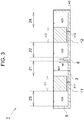
- FIG. 3 is a schematic sectional view when the cell culture chip 1 is cut along line X1-X1 in FIG. 2 .
- FIG. 4 is a schematic sectional view when the cell culture chip 1 is cut along line X2-X2 in FIG. 2 .
- FIG. 5 is a schematic sectional view when the cell culture chip 1 is cut along line X3-X3 in FIG. 2 .
- the cell culture chip 1 illustrated in FIGs. 1 to 5 includes a first culture chamber 11, a second culture chamber 12, a first well 21, a second well 22, a third well 23, and a fourth well 24.
- Each of the first culture chamber 11, the second culture chamber 12, the first well 21, the second well 22, the third well 23, and the fourth well 24 constitutes a cylindrical or tubular space enclosed by a wall portion.
- the first culture chamber 11 and the second culture chamber 12 constitute spaces for culturing cells.
- the cell culture chip 1 includes a bottom portion 3 and a main body 5.
- the main body 5 has four through holes, and one plane of each through hole is in contact with the bottom portion 3 to define each of the wells (21 to 24).
- the main body 5 has a pair of thin tubular recesses in a surface of the main body 5 on the side near the bottom portion 3. Regions between the recesses and the bottom portion 3 define the culture chambers (11 and 12).
- One end of the first culture chamber 11 is connected to the third well 23, and the other end of the first culture chamber 11 is connected to the first well 21.
- One end of the second culture chamber 12 is connected to the second well 22, and the other end of the second culture chamber 12 is connected to the fourth well 24.
- the first culture chamber 11 and the second culture chamber 12 are disposed at positions separated from each other.
- a partition wall 6 is formed between the first well 21 and the second well 22.
- the partition wall 6 constitutes a "connecting portion".
- the third well 23 and the fourth well 24 are completely separated by a wall of the main body 5.
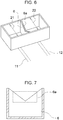
- FIG. 6 is a schematic perspective view illustrating only portions corresponding to the first well 21 and the second well 22 extracted from the cell culture chip 1.
- the partition wall 6 is provided between the first well 21 and the second well 22.
- the partition wall 6 has a cutout portion 6a having different heights in accordance with a position of the cutout portion 6a.
- FIG. 7 is a schematic plan view of the partition wall 6 when viewed in a direction from the first well 21 toward the second well 22.
- a height h11 of the first culture chamber 11 is lower than a height h6 of the partition wall 6. Moreover, a height h21 of the first well 21 is higher than the height h6 of the partition wall 6.
- a height (thickness) w3 of the bottom portion 3 is about 1 mm, or preferably 100 ⁇ m or more and 2 mm or less.
- the height h21 of the first well 21, a height h22 of the second well 22, a height h23 of the third well 23, and a height h24 of the fourth well 24 each are about 5 mm.
- the height h11 of the first culture chamber 11 and a height h12 of the second culture chamber 12 each are about 400 ⁇ m.
- the height h6 of the partition wall 6 is about 3 mm.
- the size of a plane (opening plane) of each of the first well 21, the second well 22, the third well 23, and the fourth well 24 in a direction parallel to the surface of the bottom portion 3 is about 3.5 mm square.
- the distance from an end surface 23a of the third well 23 located opposite to the first well 21 to an end surface 21a of the first well 21 located opposite to the third well 23 is about 12.5 mm.
- the distance from an end surface 22a of the second well 22 located opposite to the fourth well 24 to an end surface 24a of the fourth well 24 located opposite to the second well 22 is about 12.5 mm.
- a length t11 of the first culture chamber 11 in the longitudinal direction and a length t12 of the second culture chamber 12 in the longitudinal direction each are about 5.5 mm.
- Both the bottom portion 3 and the main body 5 constituting the cell culture chip 1 are preferably made of a transparent material. Thus, the cells cultured in the first culture chamber 11 and the second culture chamber 12 can be visually recognized from the outside of the cell culture chip 1.
- the bottom portion 3 and the main body 5 constituting the cell culture chip 1 are preferably made of a material applicable to injection molding.
- a culture solution 42 containing a predetermined cell 41 is supplied from the third well 23 side, and a culture solution 52 containing a predetermined cell 51 is supplied from the fourth well 24 side.
- the cell 51 is a target cell for evaluation of the influence of a physiologically active substance released from the cell 41.
- the cell 41 may be a liver cell and the cell 51 may be a kidney cell.
- the cell 41 may be a heart cell and the cell 51 may be a kidney cell. The reverse of such an example is also possible.
- a micropipette can be used to supply the culture solutions (42 and 52).
- the culture solution 42 supplied from the third well 23 side reaches the inside of the first well 21 through the first culture chamber 11.
- the culture solution 52 supplied from the fourth well 24 side reaches the inside of the second well 22 through the second culture chamber 12.
- the inflow amount of the culture solution 42 is set to an amount within a range in which the culture solution 42 does not flow over the partition wall 6 when the culture solution 42 reaches the inside of the first well 21.
- the inflow amount of the culture solution 52 is set to an amount within a range in which the culture solution 52 does not flow over the partition wall 6 when the culture solution 52 reaches the inside of the second well 22.
- the culture solution 42 stored in the first well 21 and the culture solution 52 stored in the second well 22 and the fourth well 24 are removed.
- a micropipette can be also used to remove the culture solutions (42, 52).
- the culture solution 42 stored in the third well 23 flows to the first well 21 side, and the state illustrated in FIG. 8A(c) is obtained.
- the culture solution 42 containing the cell 41 is held in the first culture chamber 11, and the culture solution 52 containing the cell 51 is held in the second culture chamber 12. That is, an environment in which the cell 41 is cultured in the first culture chamber 11 and the cell 51 is cultured in the second culture chamber 12 is formed.
- This step corresponds to a step (a).
- the cell 41 cultured in the first culture chamber 11 releases a physiologically active substance into the culture solution 42.
- the physiologically active substance include a cytokine, a hormone, a lipid, an extracellular matrix, a microRNA, an exosome, a nutrient, and a drug, which exhibit an endocrine action.
- an amount of the culture solution 42 within a range in which the culture solution 42 stored in the first well 21 does not flow over the partition wall 6 may be additionally supplied from the third well 23 side.
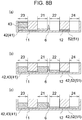
- a culture solution 43 is supplied from the third well 23 side ( FIG. 8B(a) ).
- the culture solution 43 may be made of the same material as the material of the culture solution 42, or may be made of a material different from the material of the culture solution 42 as long as the material of the culture solution 43 does not exert an influence on the cell 41.
- the culture solution 42 corresponds to a "first liquid".
- the culture solution 43 is supplied by such an amount that the culture solution 42 can flow over the partition wall 6. Consequently, the culture solution 42 containing the physiologically active substance released from the cell 41 is supplied to the second culture chamber 12 via the second well 22 ( FIG. 8B(b) and FIG. 8B(c) ). This step corresponds to a step (b).
- the process waits for a predetermined period of time in the state of FIG. 8B(c) . Accordingly, the physiologically active substance released from the cell 41 is held for a certain period of time in a state in contact with the cell 51 that has been cultured in the second culture chamber 12. Thus, it is possible to evaluate whether or not the physiologically active substance released from the cell 41 exerts an influence on the cell 51 and how the physiologically active substance has the influence on the cell 51.
- the physiologically active substance released from the cell 41 can be brought into contact with the cell 51 only by adjusting the supply amount of the culture solution 43 supplied from the third well 23 side.
- a driving mechanism such as a pump.
- the physiologically active substance released from the cell 51 does not act on the cell 41, it is possible to more accurately evaluate the influence of the physiologically active substance released from the cell 41 on the cell 51.
Landscapes
- Health & Medical Sciences (AREA)
- Chemical & Material Sciences (AREA)
- Wood Science & Technology (AREA)
- Organic Chemistry (AREA)
- Life Sciences & Earth Sciences (AREA)
- Engineering & Computer Science (AREA)
- Bioinformatics & Cheminformatics (AREA)
- Zoology (AREA)
- Biomedical Technology (AREA)
- Sustainable Development (AREA)
- Microbiology (AREA)
- Biotechnology (AREA)
- Biochemistry (AREA)
- General Engineering & Computer Science (AREA)
- General Health & Medical Sciences (AREA)
- Genetics & Genomics (AREA)
- Clinical Laboratory Science (AREA)
- Dispersion Chemistry (AREA)
- Apparatus Associated With Microorganisms And Enzymes (AREA)
- Micro-Organisms Or Cultivation Processes Thereof (AREA)
Abstract
Description
- The present invention relates to cell culture chips, and particularly relates to a cell culture chip used for independently culturing a plurality of cells. The present invention also relates to a cell culture method using the cell culture chip.
- Conventionally, a cell culture chip including a plurality of wells has been known for the purpose of simultaneously culturing multiple cells. Such a cell culture chip may be referred to as a "multi-well" culture chip.
FIGs. 10 and 11 illustrate a structure of a multi-well cell culture chip of related art.FIG. 10 corresponds to a perspective view, andFIG. 11 corresponds to a sectional view. - A
cell culture chip 100 illustrated inFIG. 10 includes sixwells 110 having the same shape. More specifically, thecell culture chip 100 includes anupper tray 120 having through holes and alower tray 130 disposed in contact with theupper tray 120. A surface of thelower tray 130 and the through holes of theupper tray 120 define thewells 110. - As illustrated in
FIG. 11 ,cells 140 are placed on a bottom surface of each well 110, and aculture solution 150 is added to cover thecells 140. - However, in the configuration of the
cell culture chip 100 illustrated inFIG. 10 , since thewells 110 are independent from one another, it is not possible to use thecell culture chip 100 for the purpose of examining interactions betweencells 140 placed in therespective wells 110. In such a viewpoint, for example,PTL 1 listed below discloses a cell culture chip in which different wells can store a common culture solution (culture medium). - PTL 1:
Japanese Laid-open Patent Publication No. 2007-510429 -
FIGs. 12 and 13 illustrate an example of a structure of a multi-well cell culture chip disclosed inPTL 1.FIG. 12 corresponds to a perspective view, andFIG. 13 corresponds to a sectional view. - A multi-well
cell culture chip 200 illustrated inFIG. 12 includes amain body 205 and anouter wall 215 disposed on anupper surface 210 of themain body 205. Six recesses are provided at predetermined positions of theupper surface 210 of themain body 205 to definewells 220. - When cells are cultured,
cells 140 are placed on a bottom surface of each well 220, and aculture solution 150 is added to cover thecells 140. Here, as illustrated inFIG. 13 , theculture solution 150 is supplied to thecell culture chip 200 until the liquid level of theculture solution 150 reaches a position exceeding a top plane of each well 220. At this time, thewells 220 communicate with one another via theculture solution 150. Thus, it is possible to observe the influence of a physiologically active substance released from acell 140 cultured in a certain well 220 on anothercell 140 cultured in another well 220. - The inventors have studied functions and effects of ES/iPS cells by simulating an environment closer to that in a living body. In the course of such studies, when the simulation of the environment close to that in the living body is considered, it has been found that there is a need to simultaneously culture a certain cell A and another cell B, and observe the influence of a physiologically active substance Xa released from the cell A on the cell B in a state in which the influence of a physiologically active substance Xb released from the cell B on the cell A is eliminated.
- However, in the case of the
cell culture chip 200 illustrated inFIGs. 12 and 13 , although it is possible to observe the interaction between thecells 140 cultured in all thewells 220, it is not possible to use thecell culture chip 200 for the purpose of observing the influence from a specific certain cell to another specific certain cell. - As another method, a method of culturing cells while forcibly causing a culture solution to flow in one direction using a driving mechanism such as a pump can be considered. However, if a driving mechanism such as a pump is used when cells are cultured, there are problems in that the size of the chip markedly increases and the handling of a power source becomes complicated. As long as the size of the chip can be reduced, multiple cells can be cultured within the same area, thereby markedly increasing the efficiency of the study.
- In view of the above problems, an object of the present invention is to provide a cell culture chip and a cell culture method that enables observation of interactions between cells with a direction without additionally using a driving mechanism.
- A cell culture chip according to the present invention includes
a first culture chamber capable of culturing a cell;
a second culture chamber disposed at a position separated from the first culture chamber and being capable of culturing a cell independently from the first culture chamber;
a first well connected to the first culture chamber and capable of storing a liquid;
a second well connected to the second culture chamber and capable of storing a liquid; and
a connecting portion that, when a liquid level of a first liquid stored in the first well reaches a predetermined height position or higher, allows the first liquid to flow from the first well into the second well. - According to the cell culture chip, the first liquid can flow into the second well from the first well only by controlling the solution amount of the culture solution. Since the first liquid is stored in the first well connected to the first culture chamber, the first liquid contains a physiologically active substance (hereinafter, referred to as a "first physiologically active substance") released from the cell (hereinafter referred to as a "first cell") cultured in the first culture chamber. Thus, when the first liquid flows into the second culture chamber through the second well, the first physiologically active substance contained in the first liquid comes into contact with a cell (hereinafter, referred to as a "second cell") cultured in the second culture chamber. Consequently, the influence of the first physiologically active substance on the second cell can be observed.
- In contrast, according to the cell culture chip, the culture solution in contact with the second culture chamber does not flow to the first culture chamber side. Consequently, the physiologically active substance (hereinafter, referred to as a "second physiologically active substance") released from the second cell can be prevented from exerting an influence on the first cell.
- With the cell culture chip, the first physiologically active substance can be brought into contact with the second cell only by adjusting the supply amount of the culture solution. Thus, it is not necessary to additionally provide a driving mechanism such as a pump. Consequently, the size of the cell culture chip can be reduced.
- In the cell culture chip,
the first well and the second well may be adjacent to each other via a partition wall, and
the connecting portion may be constituted by the partition wall. - In this case, the partition wall may include a cutout portion having a bottom surface whose height position varies in accordance with a place of the bottom surface.
- According to the above configuration, it is possible to freely adjust the speed at which the first liquid flows into the second well and the amount of the culture solution supplied to cause the first liquid to flow into the second well in accordance with the shape of the cutout portion.
- In the cell culture chip,
the first well and the second well may be adjacent to each other via a gutter-shaped flow path, and
the connecting portion may be constituted by the gutter-shaped flow path. - In the cell culture chip,
a bottom surface of the first well and a bottom surface of the first culture chamber may be constituted by a common surface, and
a length of the first culture chamber in a vertical direction may be shorter than a length from the bottom surface of the first well to the predetermined height position. - According to this configuration, since the bottom surface of the first well and the bottom surface of the first culture chamber are common, the cell culture chip can be manufactured by a simple method.
- The cell culture chip may include
a third well connected to the first culture chamber at a position opposite to the first well; and
a fourth well connected to the second culture chamber at a position opposite to the second well. - According to the above configuration, the first liquid stored in the first well is pushed out to the second well side by supplying the culture solution from the third well side. Moreover, the liquid flowing through the second culture chamber can be taken out from the fourth well side.
- In the above-described configuration, a bottom surface of the first well, a bottom surface of the first culture chamber, a bottom surface of the third well, a bottom surface of the second well, a bottom surface of the second culture chamber, and a bottom surface of the fourth well may be all constituted by a common surface.
- A cell culture method according to the present invention includes
a step (a) of culturing a cell independently in each of the first culture chamber and the second culture chamber; and
a step (b) of supplying a culture solution through the first culture chamber to raise a height position of the liquid level of the first liquid stored in the first well. - In the step (b), an inflow amount of the culture solution is adjusted such that the first liquid flows into the second culture chamber through the connecting portion and the second well.
- In the cell culture method,
the cell culture chip may include a third well connected to the first culture chamber at a position opposite to the first well, and
the step (b) may be a step of supplying the culture solution from the third well. - According to the present invention, a cell culture chip and a cell culture method that enables observation of interactions between cells with a direction without additionally using a driving mechanism are implemented.
-
- [
FIG. 1] FIG. 1 is a photograph indicating a structure of an embodiment of a cell culture chip. - [
FIG. 2] FIG. 2 is a plan view schematically illustrating the structure of the cell culture chip illustrated inFIG. 1 . - [
FIG. 3] FIG. 3 is a sectional view taken along line X1-X1 inFIG. 2 . - [
FIG. 4] FIG. 4 is a sectional view taken along line X2-X2 inFIG. 2 . - [
FIG. 5] FIG. 5 is a sectional view taken along line X3-X3 inFIG. 2 . - [
FIG. 6] FIG. 6 is a schematic perspective view illustrating portions corresponding to a first well and a second well. - [
FIG. 7] FIG. 7 is a schematic plan view of a partition wall when viewed in a direction from the first well toward the second well inFIG. 6 . - [
FIG. 8A] FIG. 8A is a process diagram schematically illustrating a method of using the cell culture chip. - [
FIG. 8B] FIG. 8B is a process diagram schematically illustrating the method of using the cell culture chip. - [
FIG. 9] FIG. 9 is a perspective view schematically illustrating a structure of another embodiment of a cell culture chip. - [
FIG. 10] FIG. 10 is a perspective view schematically illustrating an example of a structure of a multi-well cell culture chip of related art. - [
FIG. 11] FIG. 11 is a sectional view schematically illustrating the structure of the cell culture chip illustrated inFIG. 10 . - [
FIG. 12] FIG. 12 is a perspective view schematically illustrating an example of a structure of a multi-well cell culture chip of related art. - [
FIG. 13] FIG. 13 is a sectional view schematically illustrating the structure of the cell culture chip illustrated inFIG. 12 . - A cell culture chip and a cell culture method according to the present invention will be described with reference to the drawings. It should be noted that the following drawings are merely schematically illustrated. That is, the dimensional ratios on the drawings and the actual dimensional ratios do not necessarily coincide with each other, and the dimensional ratios do not necessarily coincide with each other between the drawings.
- [Structure]
FIG. 1 is a photograph indicating a structure of an embodiment of a cell culture chip.FIG. 2 is a plan view schematically illustrating the structure of thecell culture chip 1 illustrated inFIG. 1 .FIG. 3 is a schematic sectional view when thecell culture chip 1 is cut along line X1-X1 inFIG. 2 .FIG. 4 is a schematic sectional view when thecell culture chip 1 is cut along line X2-X2 inFIG. 2 .FIG. 5 is a schematic sectional view when thecell culture chip 1 is cut along line X3-X3 inFIG. 2 . - The
cell culture chip 1 illustrated inFIGs. 1 to 5 includes afirst culture chamber 11, asecond culture chamber 12, afirst well 21, asecond well 22, athird well 23, and afourth well 24. Each of thefirst culture chamber 11, thesecond culture chamber 12, thefirst well 21, thesecond well 22, thethird well 23, and thefourth well 24 constitutes a cylindrical or tubular space enclosed by a wall portion. Thefirst culture chamber 11 and thesecond culture chamber 12 constitute spaces for culturing cells. - In this embodiment, the
cell culture chip 1 includes abottom portion 3 and amain body 5. Themain body 5 has four through holes, and one plane of each through hole is in contact with thebottom portion 3 to define each of the wells (21 to 24). Moreover, themain body 5 has a pair of thin tubular recesses in a surface of themain body 5 on the side near thebottom portion 3. Regions between the recesses and thebottom portion 3 define the culture chambers (11 and 12). - One end of the
first culture chamber 11 is connected to thethird well 23, and the other end of thefirst culture chamber 11 is connected to thefirst well 21. One end of thesecond culture chamber 12 is connected to thesecond well 22, and the other end of thesecond culture chamber 12 is connected to thefourth well 24. - As illustrated in
FIGs. 1 to 4 , thefirst culture chamber 11 and thesecond culture chamber 12 are disposed at positions separated from each other. In addition, apartition wall 6 is formed between thefirst well 21 and thesecond well 22. In the present embodiment, thepartition wall 6 constitutes a "connecting portion". In contrast, as illustrated inFIG. 5 , thethird well 23 and thefourth well 24 are completely separated by a wall of themain body 5. -
FIG. 6 is a schematic perspective view illustrating only portions corresponding to thefirst well 21 and thesecond well 22 extracted from thecell culture chip 1. Thepartition wall 6 is provided between thefirst well 21 and thesecond well 22. In the present embodiment, thepartition wall 6 has acutout portion 6a having different heights in accordance with a position of thecutout portion 6a.FIG. 7 is a schematic plan view of thepartition wall 6 when viewed in a direction from thefirst well 21 toward thesecond well 22. - A height h11 of the
first culture chamber 11 is lower than a height h6 of thepartition wall 6. Moreover, a height h21 of thefirst well 21 is higher than the height h6 of thepartition wall 6. - An example of the dimensions is as follows. A height (thickness) w3 of the
bottom portion 3 is about 1 mm, or preferably 100 µm or more and 2 mm or less. The height h21 of thefirst well 21, a height h22 of thesecond well 22, a height h23 of thethird well 23, and a height h24 of thefourth well 24 each are about 5 mm. The height h11 of thefirst culture chamber 11 and a height h12 of thesecond culture chamber 12 each are about 400 µm. The height h6 of thepartition wall 6 is about 3 mm. The size of a plane (opening plane) of each of thefirst well 21, thesecond well 22, thethird well 23, and thefourth well 24 in a direction parallel to the surface of thebottom portion 3 is about 3.5 mm square. The distance from anend surface 23a of thethird well 23 located opposite to thefirst well 21 to anend surface 21a of thefirst well 21 located opposite to thethird well 23 is about 12.5 mm. The distance from anend surface 22a of thesecond well 22 located opposite to thefourth well 24 to anend surface 24a of thefourth well 24 located opposite to thesecond well 22 is about 12.5 mm. A length t11 of thefirst culture chamber 11 in the longitudinal direction and a length t12 of thesecond culture chamber 12 in the longitudinal direction each are about 5.5 mm. - Both the
bottom portion 3 and themain body 5 constituting thecell culture chip 1 are preferably made of a transparent material. Thus, the cells cultured in thefirst culture chamber 11 and thesecond culture chamber 12 can be visually recognized from the outside of thecell culture chip 1. In addition, thebottom portion 3 and themain body 5 constituting thecell culture chip 1 are preferably made of a material applicable to injection molding. - [Method of Use] Hereinafter, an example of a method of using the above-described
cell culture chip 1 will be described with reference toFIG. 8A andFIG. 8B . - As illustrated in 8A(a), a
culture solution 42 containing apredetermined cell 41 is supplied from thethird well 23 side, and aculture solution 52 containing apredetermined cell 51 is supplied from thefourth well 24 side. It should be noted that thecell 51 is a target cell for evaluation of the influence of a physiologically active substance released from thecell 41. As an example, thecell 41 may be a liver cell and thecell 51 may be a kidney cell. As another example, thecell 41 may be a heart cell and thecell 51 may be a kidney cell. The reverse of such an example is also possible. - To supply the culture solutions (42 and 52), for example, a micropipette can be used. The
culture solution 42 supplied from thethird well 23 side reaches the inside of thefirst well 21 through thefirst culture chamber 11. Theculture solution 52 supplied from thefourth well 24 side reaches the inside of thesecond well 22 through thesecond culture chamber 12. - At this time, the inflow amount of the
culture solution 42 is set to an amount within a range in which theculture solution 42 does not flow over thepartition wall 6 when theculture solution 42 reaches the inside of thefirst well 21. Likewise, the inflow amount of theculture solution 52 is set to an amount within a range in which theculture solution 52 does not flow over thepartition wall 6 when theculture solution 52 reaches the inside of thesecond well 22. - Next, as illustrated in
FIG. 8A(b) , theculture solution 42 stored in thefirst well 21 and theculture solution 52 stored in thesecond well 22 and thefourth well 24 are removed. A micropipette can be also used to remove the culture solutions (42, 52). Thereafter, theculture solution 42 stored in thethird well 23 flows to thefirst well 21 side, and the state illustrated inFIG. 8A(c) is obtained. - By this step, the
culture solution 42 containing thecell 41 is held in thefirst culture chamber 11, and theculture solution 52 containing thecell 51 is held in thesecond culture chamber 12. That is, an environment in which thecell 41 is cultured in thefirst culture chamber 11 and thecell 51 is cultured in thesecond culture chamber 12 is formed. This step corresponds to a step (a). - By maintaining this state for a predetermined period of time, the
cell 41 cultured in thefirst culture chamber 11 releases a physiologically active substance into theculture solution 42. Examples of the physiologically active substance include a cytokine, a hormone, a lipid, an extracellular matrix, a microRNA, an exosome, a nutrient, and a drug, which exhibit an endocrine action. If necessary, an amount of theculture solution 42 within a range in which theculture solution 42 stored in thefirst well 21 does not flow over thepartition wall 6 may be additionally supplied from thethird well 23 side. - After a predetermined period of time has elapsed, a
culture solution 43 is supplied from thethird well 23 side (FIG. 8B(a) ). Theculture solution 43 may be made of the same material as the material of theculture solution 42, or may be made of a material different from the material of theculture solution 42 as long as the material of theculture solution 43 does not exert an influence on thecell 41. Theculture solution 42 corresponds to a "first liquid". Thus, the liquid level of theculture solution 42 stored in thefirst well 21 rises. Theculture solution 43 is supplied by such an amount that theculture solution 42 can flow over thepartition wall 6. Consequently, theculture solution 42 containing the physiologically active substance released from thecell 41 is supplied to thesecond culture chamber 12 via the second well 22 (FIG. 8B(b) and FIG. 8B(c) ). This step corresponds to a step (b). - Then, the process waits for a predetermined period of time in the state of
FIG. 8B(c) . Accordingly, the physiologically active substance released from thecell 41 is held for a certain period of time in a state in contact with thecell 51 that has been cultured in thesecond culture chamber 12. Thus, it is possible to evaluate whether or not the physiologically active substance released from thecell 41 exerts an influence on thecell 51 and how the physiologically active substance has the influence on thecell 51. - As described above, according to the
cell culture chip 1, the physiologically active substance released from thecell 41 can be brought into contact with thecell 51 only by adjusting the supply amount of theculture solution 43 supplied from thethird well 23 side. Thus, it is not necessary to additionally provide a driving mechanism such as a pump. In addition, since the physiologically active substance released from thecell 51 does not act on thecell 41, it is possible to more accurately evaluate the influence of the physiologically active substance released from thecell 41 on thecell 51. - [Other Embodiments] Other embodiments will be described below.
- <1 > The
cell culture chip 1 of the above-described embodiment has the configuration in which thefirst well 21 and thesecond well 22 are separated by thepartition wall 6, and theculture solution 42 flows from thefirst well 21 to thesecond well 22 side when the liquid level of theculture solution 42 exceeds the height of thepartition wall 6. However, thecell culture chip 1 is not limited to such an embodiment. That is, instead of thepartition wall 6, thecell culture chip 1 may be configured to include a connecting portion that allows theculture solution 42 to flow into the second well 22 from thefirst well 21 only when the liquid level of theculture solution 42 exceeds a predetermined height.
As an example, as schematically illustrated inFIG. 9 , thecell culture chip 1 may be configured to include a gutter-shapedflow path 7 that connects thefirst well 21 and thesecond well 22 to each other. The gutter-shapedflow path 7 guides theculture solution 42 to thesecond well 22 side only when the liquid level of theculture solution 42 stored in thefirst well 21 exceeds a height h7 of the gutter-shapedflow path 7. With this configuration as well, the physiologically active substance released from thecell 41 can be brought into contact with thecell 51 only by adjusting the supply amount of theculture solution 43 supplied from thethird well 23 side.
As another example, thecell culture chip 1 may include a tube-shaped flow path that connects thefirst well 21 and thesecond well 22 to each other. - <2> The
cell culture chip 1 may not necessarily include thethird well 23 as long as the culture solution 42 (43) can be injected into thefirst culture chamber 11. Likewise, thecell culture chip 1 may not necessarily include thefourth well 24. - <3> In the above-described embodiment, the case where the
cell culture chip 1 includes the two culture chambers (11 and 12) has been described. However, thecell culture chip 1 may include three or more culture chambers connected in series. - <4> In the above-described embodiment, the case where the wells (21, 22, 23, and 24) and the culture chambers (11 and 12) have a common bottom surface that is the upper surface of the
bottom portion 3 has been described. This form is an example. However, it is preferable that the wells (21, 22, 23, and 24) and the culture chambers (11 and 12) have a common bottom surface in terms of facilitating the manufacturing process of thecell culture chip 1 and enabling the size of thecell culture chip 1 to be markedly reduced. - <5> In the above-described embodiment, the case where the
partition wall 6 has the shape having thecutout portion 6a has been described. However, when thecell culture chip 1 includes thepartition wall 6, thepartition wall 6 does not necessarily have the shape having thecutout portion 6a as long as the height of thepartition wall 6 is configured to be lower than the height of the other wall surfaces of thefirst well 21. When thecell culture chip 1 includes thepartition wall 6 having thecutout portion 6a, it is possible to appropriately adjust the speed at which theculture solution 42 flows to thesecond culture chamber 12 side in accordance with the shape and height position of thecutout portion 6a. -
- 1: cell culture chip
- 3: bottom portion
- 5: main body
- 6: partition wall
- 6a: cutout portion of partition wall
- 7: gutter-shaped flow path
- 11: first culture chamber
- 12: second culture chamber
- 21: first well
- 21a: wall surface of first well
- 22: second well
- 22a: wall surface of second well
- 23: third well
- 23a: wall surface of third well
- 24: fourth well
- 24a: wall surface of fourth well
- 41: cell
- 42, 43: culture solution
- 51: cell
- 52: culture solution
- 100: cell culture chip of related art
- 110: well
- 120: upper tray
- 130: lower tray
- 140: cell
- 150: culture solution
- 200: cell culture chip of related art
- 205: main body
- 210: top surface of main body
- 215: outer wall
- 220: well
Claims (9)
- A cell culture chip comprising:a first culture chamber capable of culturing a cell;a second culture chamber disposed at a position separated from the first culture chamber and being capable of culturing a cell independently from the first culture chamber;a first well connected to the first culture chamber and capable of storing a liquid;a second well connected to the second culture chamber and capable of storing a liquid; anda connecting portion that, when a liquid level of a first liquid stored in the first well reaches a predetermined height position or higher, allows the first liquid to flow from the first well into the second well.
- The cell culture chip according to claim 1,
wherein the first well and the second well are adjacent to each other via a partition wall, and
wherein the connecting portion is constituted by the partition wall. - The cell culture chip according to claim 2, wherein the partition wall includes a cutout portion having a bottom surface whose height position varies in accordance with a place of the bottom surface.
- The cell culture chip according to claim 1,
wherein the first well and the second well are adjacent to each other via a gutter-shaped flow path, and
wherein the connecting portion is constituted by the gutter-shaped flow path. - The cell culture chip according to any one of claims 1 to 4,
wherein a bottom surface of the first well and a bottom surface of the first culture chamber are constituted by a common surface, and
wherein a length of the first culture chamber in a vertical direction is shorter than a length from the bottom surface of the first well to the predetermined height position. - The cell culture chip according to any one of claims 1 to 4, comprising:a third well connected to the first culture chamber at a position opposite to the first well; anda fourth well connected to the second culture chamber at a position opposite to the second well.
- The cell culture chip according to claim 6, wherein a bottom surface of the first well, a bottom surface of the first culture chamber, a bottom surface of the third well, a bottom surface of the second well, a bottom surface of the second culture chamber, and a bottom surface of the fourth well are all constituted by a common surface.
- A cell culture method using the cell culture chip according to claim 1, the method comprising:a step (a) of culturing a cell independently in each of the first culture chamber and the second culture chamber; anda step (b) of supplying a culture solution through the first culture chamber to raise a height position of the liquid level of the first liquid stored in the first well,wherein, in the step (b), an inflow amount of the culture solution is adjusted such that the first liquid flows into the second culture chamber through the connecting portion and the second well.
- The cell culture method according to claim 8,
wherein the cell culture chip includes a third well connected to the first culture chamber at a position opposite to the first well, and
wherein the step (b) is a step of supplying the culture solution from the third well.
Applications Claiming Priority (2)
| Application Number | Priority Date | Filing Date | Title |
|---|---|---|---|
| JP2018154791A JP7223311B2 (en) | 2018-08-21 | 2018-08-21 | CELL CULTURE CHIP AND CELL CULTURE METHOD USING THE SAME |
| PCT/JP2019/026244 WO2020039756A1 (en) | 2018-08-21 | 2019-07-02 | Cell culture chip and cell culture method using same |
Publications (2)
| Publication Number | Publication Date |
|---|---|
| EP3842512A1 true EP3842512A1 (en) | 2021-06-30 |
| EP3842512A4 EP3842512A4 (en) | 2022-06-22 |
Family
ID=69592576
Family Applications (1)
| Application Number | Title | Priority Date | Filing Date |
|---|---|---|---|
| EP19851192.5A Withdrawn EP3842512A4 (en) | 2018-08-21 | 2019-07-02 | CELL CULTURE CHIP AND CELL CULTURE METHOD USING THE SAME |
Country Status (5)
| Country | Link |
|---|---|
| US (1) | US12227724B2 (en) |
| EP (1) | EP3842512A4 (en) |
| JP (2) | JP7223311B2 (en) |
| CN (1) | CN112567015B (en) |
| WO (1) | WO2020039756A1 (en) |
Families Citing this family (3)
| Publication number | Priority date | Publication date | Assignee | Title |
|---|---|---|---|---|
| JP7452481B2 (en) * | 2021-03-25 | 2024-03-19 | 豊田合成株式会社 | Cell culture container and cell culture method |
| CN118119699A (en) * | 2021-08-19 | 2024-05-31 | 贾夫林生物科技有限公司 | Microfluidic Systems and Support Modules |
| CN114854583B (en) * | 2022-03-31 | 2026-01-27 | 珠海横琴国草堂中医药科技有限公司 | Cell culture chip and single-circulation fluid device |
Family Cites Families (17)
| Publication number | Priority date | Publication date | Assignee | Title |
|---|---|---|---|---|
| US5422270A (en) * | 1987-05-19 | 1995-06-06 | The United States Of America As Represented By The Department Of Health And Human Services | One-step tray test for release of soluble mediators and apparatus therefore |
| GB9209175D0 (en) | 1992-04-28 | 1992-06-10 | Pirtferm Ltd | Bioreactor system |
| US7374906B2 (en) * | 2000-11-08 | 2008-05-20 | Surface Logix, Inc. | Biological assays using gradients formed in microfluidic systems |
| JP2004000163A (en) * | 2002-03-29 | 2004-01-08 | Shimadzu Corp | Cells used for cell processing |
| JP4386652B2 (en) * | 2002-04-08 | 2009-12-16 | 株式会社Eci | Toxicity test method |
| US7186548B2 (en) | 2003-11-10 | 2007-03-06 | Advanced Pharmaceutical Sciences, Inc. | Cell culture tool and method |
| JP4509632B2 (en) * | 2004-04-05 | 2010-07-21 | 株式会社アドバンス | Blood cell separation structure |
| WO2008104086A1 (en) * | 2007-03-01 | 2008-09-04 | Queen's University At Kingston | Planar electroporation apparatus and method |
| WO2010106456A2 (en) * | 2009-03-20 | 2010-09-23 | International Business Machines Corporation | Microorganism culture device and method of operation thereof |
| CN201495228U (en) * | 2009-08-07 | 2010-06-02 | 深圳职业技术学院 | cell culture vessel |
| TWI438273B (en) * | 2011-03-08 | 2014-05-21 | 長庚大學 | High-throughput perfusative microfluidic cell culture wafers for miniaturized three-dimensional cell culture |
| JP6364258B2 (en) | 2013-08-08 | 2018-07-25 | 学校法人金沢医科大学 | Culture vessel |
| CA3018696C (en) | 2015-03-23 | 2019-10-15 | SciKon Innovation, Inc. | A method and related systems for use with a fluidics device |
| KR101706750B1 (en) | 2015-08-19 | 2017-02-14 | 전남대학교산학협력단 | Multichannel cell culture dish |
| US11325130B2 (en) | 2016-02-12 | 2022-05-10 | Ginreilab Inc. | Multiwell instrument |
| EP3428265A4 (en) * | 2016-03-08 | 2019-10-23 | National Institute of Advanced Industrial Science and Technology | DEVICE AND METHOD FOR CELL CULTURE |
| EP3481553B1 (en) | 2016-07-07 | 2024-04-10 | Onexio Biosystems Llc | Use of a cell co-culture device in high throughput screening and a corresponding method |
-
2018
- 2018-08-21 JP JP2018154791A patent/JP7223311B2/en active Active
-
2019
- 2019-07-02 WO PCT/JP2019/026244 patent/WO2020039756A1/en not_active Ceased
- 2019-07-02 CN CN201980053903.7A patent/CN112567015B/en active Active
- 2019-07-02 EP EP19851192.5A patent/EP3842512A4/en not_active Withdrawn
- 2019-07-02 US US17/265,798 patent/US12227724B2/en active Active
-
2023
- 2023-01-31 JP JP2023013070A patent/JP7501689B2/en active Active
Also Published As
| Publication number | Publication date |
|---|---|
| JP2023041809A (en) | 2023-03-24 |
| JP7223311B2 (en) | 2023-02-16 |
| US20210238521A1 (en) | 2021-08-05 |
| JP7501689B2 (en) | 2024-06-18 |
| US12227724B2 (en) | 2025-02-18 |
| JP2020028237A (en) | 2020-02-27 |
| CN112567015A (en) | 2021-03-26 |
| EP3842512A4 (en) | 2022-06-22 |
| CN112567015B (en) | 2024-11-12 |
| WO2020039756A1 (en) | 2020-02-27 |
Similar Documents
| Publication | Publication Date | Title |
|---|---|---|
| JP7501689B2 (en) | Cell culture chip and cell culture method using the same | |
| DE69836562T2 (en) | CASE FOR PROCESSING A SAMPLE APPLIED ON THE SURFACE OF A CARRIER | |
| US8513165B2 (en) | Planar lipid bilayer array formed by microfluidic technique and method of analysis using planar lipid bilayer | |
| US9739699B2 (en) | Device for the study of living cells | |
| KR102260910B1 (en) | Microfluidic platform for investigating cell-based interactions | |
| EP3321681A1 (en) | Microfluidic screening system | |
| CA2786432C (en) | Cell counting slide with lateral reservoir for promoting uniform cell distribution | |
| CN113388516B (en) | Culture device | |
| EP1746154B1 (en) | Culture chamber, culture apparatus and liquid supplying method for cell or tissue cultivation | |
| CN106885807A (en) | Extensive live organism screening system based on microflow control technique | |
| US10606058B2 (en) | Microscope slide for liquid cultures | |
| CN219861383U (en) | Cell culture unit and cell culture device | |
| US20200239821A1 (en) | Microfluidic perfusion cell culture system | |
| JP7766348B2 (en) | Artificial three-dimensional tissue manufacturing device and artificial three-dimensional tissue manufacturing method | |
| KR20210067562A (en) | Cell culture device | |
| AU2020349664B2 (en) | Millifluidic device for advanced cultures of biological agents | |
| US11767498B2 (en) | In vitro tissue plate | |
| CN219546980U (en) | Double-chamber three-dimensional biochip | |
| US20250019636A1 (en) | Device for separating motile cells | |
| CN218842121U (en) | Incubator and cell culture apparatus | |
| CN109251859B (en) | Cell culture device and cell box thereof | |
| KR102132630B1 (en) | Rapid Cell Culture Device With Island Structure | |
| WO2010124663A2 (en) | Method for adding, removing or exchange a liquid medium in culturing biological cells and culture device | |
| US20250145922A1 (en) | Microphysiological system device | |
| KR102919464B1 (en) | Microfluidic apparatus, method of manufacturing the microfluidic apparatus, method of combining microfluidic concentration using the microfluidic apparatus and method of confirming drug response of cells using the microfluidic apparatus |
Legal Events
| Date | Code | Title | Description |
|---|---|---|---|
| STAA | Information on the status of an ep patent application or granted ep patent |
Free format text: STATUS: THE INTERNATIONAL PUBLICATION HAS BEEN MADE |
|
| PUAI | Public reference made under article 153(3) epc to a published international application that has entered the european phase |
Free format text: ORIGINAL CODE: 0009012 |
|
| STAA | Information on the status of an ep patent application or granted ep patent |
Free format text: STATUS: REQUEST FOR EXAMINATION WAS MADE |
|
| 17P | Request for examination filed |
Effective date: 20210305 |
|
| AK | Designated contracting states |
Kind code of ref document: A1 Designated state(s): AL AT BE BG CH CY CZ DE DK EE ES FI FR GB GR HR HU IE IS IT LI LT LU LV MC MK MT NL NO PL PT RO RS SE SI SK SM TR |
|
| DAV | Request for validation of the european patent (deleted) | ||
| DAX | Request for extension of the european patent (deleted) | ||
| A4 | Supplementary search report drawn up and despatched |
Effective date: 20220525 |
|
| RIC1 | Information provided on ipc code assigned before grant |
Ipc: C12M 3/06 20060101ALI20220519BHEP Ipc: C12M 1/32 20060101ALI20220519BHEP Ipc: C12N 5/071 20100101ALI20220519BHEP Ipc: C12N 1/00 20060101ALI20220519BHEP Ipc: C12M 3/00 20060101ALI20220519BHEP Ipc: C12M 1/00 20060101AFI20220519BHEP |
|
| STAA | Information on the status of an ep patent application or granted ep patent |
Free format text: STATUS: EXAMINATION IS IN PROGRESS |
|
| 17Q | First examination report despatched |
Effective date: 20240528 |
|
| GRAP | Despatch of communication of intention to grant a patent |
Free format text: ORIGINAL CODE: EPIDOSNIGR1 |
|
| STAA | Information on the status of an ep patent application or granted ep patent |
Free format text: STATUS: GRANT OF PATENT IS INTENDED |
|
| INTG | Intention to grant announced |
Effective date: 20250606 |
|
| STAA | Information on the status of an ep patent application or granted ep patent |
Free format text: STATUS: THE APPLICATION IS DEEMED TO BE WITHDRAWN |
|
| 18D | Application deemed to be withdrawn |
Effective date: 20251007 |