EP3842371B1 - Yarn tensioning system for keeping a yarn which is taken from a yarn storage system to a yarn take-off system of a weaving machine under tension - Google Patents
Yarn tensioning system for keeping a yarn which is taken from a yarn storage system to a yarn take-off system of a weaving machine under tension Download PDFInfo
- Publication number
- EP3842371B1 EP3842371B1 EP21150976.5A EP21150976A EP3842371B1 EP 3842371 B1 EP3842371 B1 EP 3842371B1 EP 21150976 A EP21150976 A EP 21150976A EP 3842371 B1 EP3842371 B1 EP 3842371B1
- Authority
- EP
- European Patent Office
- Prior art keywords
- yarn
- tensioning system
- motor
- tension
- brake roller
- Prior art date
- Legal status (The legal status is an assumption and is not a legal conclusion. Google has not performed a legal analysis and makes no representation as to the accuracy of the status listed.)
- Active
Links
- 238000009941 weaving Methods 0.000 title claims description 35
- 238000012544 monitoring process Methods 0.000 claims description 13
- 238000004891 communication Methods 0.000 claims description 9
- 238000004804 winding Methods 0.000 claims description 4
- 239000002759 woven fabric Substances 0.000 description 4
- 238000000034 method Methods 0.000 description 3
- 238000009732 tufting Methods 0.000 description 3
- 239000003086 colorant Substances 0.000 description 2
- 235000012771 pancakes Nutrition 0.000 description 2
- 238000005452 bending Methods 0.000 description 1
- 230000015572 biosynthetic process Effects 0.000 description 1
- 239000011248 coating agent Substances 0.000 description 1
- 238000000576 coating method Methods 0.000 description 1
- 238000001514 detection method Methods 0.000 description 1
- 238000005259 measurement Methods 0.000 description 1
- 238000012986 modification Methods 0.000 description 1
- 230000004048 modification Effects 0.000 description 1
Images


Classifications
-
- B—PERFORMING OPERATIONS; TRANSPORTING
- B65—CONVEYING; PACKING; STORING; HANDLING THIN OR FILAMENTARY MATERIAL
- B65H—HANDLING THIN OR FILAMENTARY MATERIAL, e.g. SHEETS, WEBS, CABLES
- B65H59/00—Adjusting or controlling tension in filamentary material, e.g. for preventing snarling; Applications of tension indicators
- B65H59/10—Adjusting or controlling tension in filamentary material, e.g. for preventing snarling; Applications of tension indicators by devices acting on running material and not associated with supply or take-up devices
- B65H59/18—Driven rotary elements
-
- B—PERFORMING OPERATIONS; TRANSPORTING
- B65—CONVEYING; PACKING; STORING; HANDLING THIN OR FILAMENTARY MATERIAL
- B65H—HANDLING THIN OR FILAMENTARY MATERIAL, e.g. SHEETS, WEBS, CABLES
- B65H51/00—Forwarding filamentary material
- B65H51/20—Devices for temporarily storing filamentary material during forwarding, e.g. for buffer storage
-
- B—PERFORMING OPERATIONS; TRANSPORTING
- B65—CONVEYING; PACKING; STORING; HANDLING THIN OR FILAMENTARY MATERIAL
- B65H—HANDLING THIN OR FILAMENTARY MATERIAL, e.g. SHEETS, WEBS, CABLES
- B65H57/00—Guides for filamentary materials; Supports therefor
- B65H57/12—Tubes
-
- B—PERFORMING OPERATIONS; TRANSPORTING
- B65—CONVEYING; PACKING; STORING; HANDLING THIN OR FILAMENTARY MATERIAL
- B65H—HANDLING THIN OR FILAMENTARY MATERIAL, e.g. SHEETS, WEBS, CABLES
- B65H59/00—Adjusting or controlling tension in filamentary material, e.g. for preventing snarling; Applications of tension indicators
- B65H59/02—Adjusting or controlling tension in filamentary material, e.g. for preventing snarling; Applications of tension indicators by regulating delivery of material from supply package
- B65H59/06—Adjusting or controlling tension in filamentary material, e.g. for preventing snarling; Applications of tension indicators by regulating delivery of material from supply package by devices acting on material leaving the package
-
- D—TEXTILES; PAPER
- D03—WEAVING
- D03D—WOVEN FABRICS; METHODS OF WEAVING; LOOMS
- D03D39/00—Pile-fabric looms
- D03D39/02—Axminster looms, i.e. wherein pile tufts are inserted during weaving
-
- D—TEXTILES; PAPER
- D03—WEAVING
- D03D—WOVEN FABRICS; METHODS OF WEAVING; LOOMS
- D03D49/00—Details or constructional features not specially adapted for looms of a particular type
- D03D49/04—Control of the tension in warp or cloth
- D03D49/12—Controlling warp tension by means other than let-off mechanisms
- D03D49/16—Warp supplied by creel
-
- B—PERFORMING OPERATIONS; TRANSPORTING
- B65—CONVEYING; PACKING; STORING; HANDLING THIN OR FILAMENTARY MATERIAL
- B65H—HANDLING THIN OR FILAMENTARY MATERIAL, e.g. SHEETS, WEBS, CABLES
- B65H2701/00—Handled material; Storage means
- B65H2701/30—Handled filamentary material
- B65H2701/31—Textiles threads or artificial strands of filaments
Definitions
- the present invention relates to a yarn tensioning system for keeping at least one yarn which is taken from a yarn storage system in a first direction to a yarn take-off system of a weaving machine under tension, comprising a brake roller which is rotatably arranged in the yarn tensioning system and around which the yarn is at least partially wound in order to keep this yarn under tension between the brake roller and the yarn take-off system.
- the present invention relates to a weaving machine comprising such a yarn tensioning system.
- Yarn tensioning systems and methods for keeping yarn which is taken from a yarn storage system to a yarn take-off system in a weaving machine under tension are used in all kinds of weaving machines, such as inter alia carpet weaving machines, velvet weaving machines, wire weaving machines and flat weaving machines.
- the yarn storage system is typically a bobbin creel.
- This bobbin creel may in this case be a typical bobbin creel for a weaving machine or a typical bobbin creel for a tufting machine, which is used atypically with a weaving machine.
- the longitudinal axis of the bobbins is more or less perpendicular to the path to be followed by the yarns and the yarn is taken off along the direction of the path. In this case, the bobbin rotates continuously.
- the yarn With a typical bobbin creel for a tufting machine, the yarn is taken off in the direction of the longitudinal axis of the bobbin. The bobbin is virtually at a standstill.
- the yarn When supplying yarns to a tufting machine using such a bobbin creel, the yarn is supplied as tensionless as possible, with this yarn being guided in tubes.
- weights are for example used to keep the warp threads under tension.
- the yarn take-off system may be, for example, the weaving zone in a weaving machine, or may be an intermediate store of yarns, in which the yarns of a bobbin creel are redistributed according to the further desired use in the weaving machine and/or assembled to form new yarns which are gathered at this intermediate store for further use thereof in the weaving machine.
- the yarn tensioning system described in EP 1 077 276 A1 is a yarn tensioning system for keeping a warp thread running from a bobbin to a weaving zone of a weaving machine under tension and, if necessary, drawing it back.
- the warp thread is arranged over two friction rods.
- a first brake roller runs over the warp thread between both friction rods.
- a second brake roller runs over the warp thread between the second friction rod and a guide grid. Weights are suspended from the brake rollers. The weights and the friction rods ensure a tension of the yarn which is as even as possible.
- yarn recuperation is often required. Such yarn recuperation may be required, for example, due to shed formation. Yarn recuperation may also be required after a broken yarn has been repaired.
- the motor is furthermore actuable in motor operation to recuperate the yarn between the brake roller and the yarn take-off system in a second direction which is opposite to the first direction.
- a yarn tensioning system for keeping at least one yarn which is taken from a yarn storage system in a first direction to a yarn take-off system of a weaving machine under tension, comprising a brake roller which is rotatably arranged in the yarn tensioning system and around which the yarn is at least partially wound in order to keep this yarn under tension between the brake roller and the yarn take-off system, in which the yarn tensioning system furthermore comprises a motor for supplying a torque to the brake roller, in which said motor is actuable in generator operation to keep the yarn under tension, in which said motor is actuable in motor operation to recuperate the yarn between the brake roller and the yarn take-off system in a second direction which is opposite to the first direction and in which this yarn tensioning system comprises a funnel-shaped guide for guiding the yarn to the brake roller and also comprises a tubular guide for guiding the yarn to the funnel-shaped guide.
- This funnel-shaped guide takes the yarn near the brake roller in as optimal way as possible.
- this funnel-shaped guide collects the surplus of yarn. In this way, no slip is caused on the brake roller during yarn recuperation, so that a good yarn tension can be guaranteed.
- the recuperated yarn does not get entangled either and does not come into undesirable contact with other components of the yarn tensioning system, which could result in, for example, yarn breakage if, for example in periods when little yarn is used, the same piece of yarn repeatedly rubs over the brake roller.
- Such a funnel-shaped guide may take several forms, but always narrows from an inlet opening, in which the yarn arrives in the funnel-shaped guide, to an outlet opening where the yarn is passed from the funnel-shaped guide to the brake roller.
- This funnel-shaped guide does not necessarily end in a tubular piece.
- This funnel-shaped guide delimits a cup-shaped cavity so as to be able to collect recuperated yarn in an optimum way in this cup-shaped cavity.
- the yarn is free to bend in the funnel-shaped guide without hampering the surrounding components.
- the funnel-shaped guide preferably does not limit the yarn with regard to the direction of folding or bending of the yarn.
- Such a yarn tensioning system is particularly suitable for applications in combination with a yarn feeding system using tubes, in which just enough yarn is provided to be able to weave, and a carpet weaving machine.
- the yarn is preferably taken to an inlet opening of the funnel-shaped guide via an outlet opening of the tubular guide and the outlet opening of the tubular guide is then preferably smaller than the inlet opening of the funnel-shaped guide.
- the yarn can be supplied virtually without tension.
- An additional advantage of such a tubular guide is the fact that the yarns cannot become entangled between themselves or between cables of the yarn tensioning system. Since there is virtually no slip, the length of the used yarn can be calculated very accurately. Accurate knowledge of this length makes it possible to replenish yarn which is about to run out in a targeted and simple way.
- a yarn tensioning system may comprise several of said brake rollers with associated motors, in which a brake roller and associated motor may be provided for each yarn to be supplied or for a number of yarns to be supplied together.
- a brake roller and associated motor may be provided for each yarn to be supplied or for a number of yarns to be supplied together.
- several separate yarn tensioning systems may also be provided, each of which comprises a brake roller with associated motor for keeping at least one of the yarns under tension.
- the tension is then preferably individually controllable by providing the motor to be individually actuable.
- a motor with a slightly higher torque can then try to recuperate the yarn slightly more quickly or to counteract slightly more than normal, so that the yarn tension is guaranteed, or if recuperation takes slightly longer than normal, can then reduce the torque of the motor, so that less energy is built up in the brake roller which will then have to be overcome by the machine.
- a yarn tensioning system will preferably also comprise a central control unit and preferably then also comprises means for making the energy generated during the generator operation of the motor immediately available to the control unit of the yarn tensioning system.
- the yarn tensioning system according to the present invention may alternatively also comprise means for storing the energy generated during the generator operation of the motor, so that the motor is driven by the stored energy during the motor operation of the motor.
- a yarn tensioning system furthermore preferably also comprises measuring means for determining the length of the yarn which is taken off by the yarn take-off system. For each brake roller it is possible to calculate the length of the yarns kept under tension by this brake roller from the number of revolutions of the brake roller or the angular rotation of the motor and the diameter of the brake roller without additional length-measuring sensors being required. When the length of the yarn is calculated in this way, the aforesaid measuring means provide the calculating means required for this purpose.
- a yarn tensioning system preferably also comprises time monitoring means to keep track of the time during which the motor operates in motor operation to recuperate the yarn and to compare this monitored time with a certain reference value.
- a yarn tensioning system also comprises communication means for receiving signals from the yarn take-off system with regard to the operation of the yarn take-off system, measuring means for measuring parameters for the operation of the yarn tensioning system and tension monitoring means for monitoring the parameters for the operation of the yarn tensioning system relative to the signals received from the yarn take-off system.
- the signals with regard to the operation of the yarn take-off system represent the current state of the yarn take-off system and may relate to the machine being at a standstill, the machine being in operation, the speed of the machine, etc.
- the tension monitoring means are preferably also provided to predict the expected operation of the yarn tensioning system on the basis of the current state reported by the yarn take-off system. For this purpose, these tension monitoring means then comprise the necessary calculating means.
- the aforesaid measuring means, calculating means, time monitoring means, communication means and/or tension monitoring means preferably form part of a central control unit of the yarn tensioning system.
- these aforesaid measuring means, calculating means, time monitoring means, communication means and/or tension monitoring means may also form part of an individual motor control unit.
- a further preferred embodiment of a yarn tensioning system according to the present invention comprises a tension measuring device for measuring the yarn tension. This makes it possible to determine the yarn tension more accurately.
- a yarn tensioning system furthermore preferably also comprises one or more indicating means for generating a signal regarding the length of the yarn taken off and/or the determined and/or measured yarn tension and/or when, based on the state of the yarn take-off system, the motor is actuated in motor operation to recuperate yarn for longer than expected and/or when the brake roller is at a standstill while the yarn take-off system is taking off yarn, etc.
- a particular embodiment of a yarn tensioning system according to the present invention comprises actuating means for actuating the motor on the basis of the yarn tension measured by the tension measuring device and communication means for communicating the measured yarn tension from the tension measuring device to the actuating means.
- a particularly preferred yarn tensioning system comprises an aforesaid brake roller and an aforesaid motor for each yarn taken from the yarn storage system, so that each yarn can be individually kept under tension.
- the motor of a yarn tensioning system is preferably a DC motor or a brushless AC motor. More preferably, this motor is a brushless DC motor, still more preferably a brushless DC motor having an external rotor (a type of motor in which the stator is stationary and the rotor rotates) provided with HALL sensors, preferably carried out as a pancake motor, due to the compactness of such a type of motor, the economic feasibility and considering little energy is released or little energy is required in the present application.
- this motor is a brushless DC motor, still more preferably a brushless DC motor having an external rotor (a type of motor in which the stator is stationary and the rotor rotates) provided with HALL sensors, preferably carried out as a pancake motor, due to the compactness of such a type of motor, the economic feasibility and considering little energy is released or little energy is required in the present application.
- the tension of the yarn can be kept constant, irrespective of the thread characteristics, and the accuracy of any measurements can be increased.
- a specific embodiment of a yarn tensioning system according to the present invention comprises therefor a tension roller which is arranged in a clamped manner against the brake roller in the yarn tensioning system to clamp the yarn between the brake roller and the tension roller.
- the brake roller may for this purpose be provided for winding the yarn around it several times.
- the yarn tensioning system may comprise a braking device for braking the yarn in order to prevent the yarn from slipping on the brake roller.
- the brake roller may comprise a running surface for at least partially winding the yarn around it, in which this running surface is provided with an anti-slip layer and/or with a profiling.
- the object of the present invention is furthermore achieved by providing a weaving machine, comprising a yarn storage system, a yarn take-off system for taking yarn from the yarn storage system and a yarn tensioning system to keep a yarn which has been taken from the yarn storage system by the yarn take-off system under tension between the yarn tensioning system and the yarn take-off system, in which the yarn tensioning system is an above-described yarn tensioning system according to the present invention.
- the figures show some examples of yarn tensioning systems (1) according to the present invention.
- These yarn tensioning systems (1) each comprise, for each yarn (2) to be tensioned, a brake roller (5) which is rotatably arranged and a motor (6) for supplying a torque to the brake roller (5).
- this yarn tensioning system (1) furthermore comprises a braking device (7) which is arranged between the yarn storage system (3) and the brake roller (5).
- the brake roller (5) is provided with flanges (9) which limit the running surface (8) for the yarn (2).
- the running surface (8) of this brake roller (5) may be provided with an anti-slip layer by coating it, for example with rubber.
- the yarn tensioning system (1) comprises a tension roller (10).
- springs (11) push the shaft (12) of this tension roller (10) towards the brake roller (5), so that the tension roller (10) is arranged in a clamped manner against the brake roller (5) to clamp the yarn (2) between the brake roller (5) and the tension roller (10).
- the yarn tensioning system (1) is configured to keep 8 yarns (2) under tension. These yarns (2) may be, for example, warp threads (2) which are fed to a carpet weaving machine as yarn take-off system (4).
- the yarn tensioning system (1) comprises a brake roller (5), a motor (6) and a tension roller (10) as in the second embodiment for each yarn (2). For the sake of clarity of the figures, only one motor (6) is shown.
- Each yarn (2) is fed through a holder (15) via a corresponding tubular guide (14) and is passed to the corresponding brake roller (5) via a funnel-shaped guide (13), wound around this brake roller (5) and fed to the yarn take-off system in a first direction (A) through an eyelet (17).
- the outlet opening (16) of the tubular guide (14) is smaller than the inlet opening to the funnel-shaped guide (13).
- the funnel-shaped guide (13) comprises a cup-shaped cavity in which the yarn (2) is collected in the case of yarn recuperation in a second direction (B).
- the motor (6) is a pancake motor (6) which is configured to supply a torque to the brake roller (5).
- the motor (6) is actuated in generator operation to keep the yarn (2) under tension.
- the motor (6) is actuated in motor operation to recuperate the yarn (2) between the brake roller (5) and the yarn take-off system (4) in a second direction (B), which is opposite to the first direction (A).
- the yarn tensioning systems (1) comprise a central control unit (not shown) and means for immediately making the energy generated during the generator operation of the motor (6) available to this central control unit of the yarn tensioning system (1).
- the yarn tensioning systems (1) could comprise means for storing energy generated during the generator operation of the motor (6), so that during the motor operation of the motor (6), the motor (6) is driven by means of the stored energy.
- the yarn tensioning systems (1) also comprise a tension measuring device (not shown) for measuring the yarn tension. This measured yarn tension is then communicated to actuating means for actuating the motor (6), preferably by means of communication means, so that this motor (6) can be actuated on the basis thereof.
- the yarn tensioning systems (1) may comprise indicating means for generating a signal with regard to the measured yarn tension and communication means for communicating the measured yarn tension of the tension measuring device to these indicating means.
- the length of the yarn (2) which is taken off by the yarn take-off system (4) can be easily determined.
Description
- The present invention relates to a yarn tensioning system for keeping at least one yarn which is taken from a yarn storage system in a first direction to a yarn take-off system of a weaving machine under tension, comprising a brake roller which is rotatably arranged in the yarn tensioning system and around which the yarn is at least partially wound in order to keep this yarn under tension between the brake roller and the yarn take-off system. In addition, the present invention relates to a weaving machine comprising such a yarn tensioning system.
- Yarn tensioning systems and methods for keeping yarn which is taken from a yarn storage system to a yarn take-off system in a weaving machine under tension are used in all kinds of weaving machines, such as inter alia carpet weaving machines, velvet weaving machines, wire weaving machines and flat weaving machines.
- In this case, the yarn storage system is typically a bobbin creel. This bobbin creel may in this case be a typical bobbin creel for a weaving machine or a typical bobbin creel for a tufting machine, which is used atypically with a weaving machine.
- With a typical bobbin creel for a weaving machine, the longitudinal axis of the bobbins is more or less perpendicular to the path to be followed by the yarns and the yarn is taken off along the direction of the path. In this case, the bobbin rotates continuously.
- With a typical bobbin creel for a tufting machine, the yarn is taken off in the direction of the longitudinal axis of the bobbin. The bobbin is virtually at a standstill. When supplying yarns to a tufting machine using such a bobbin creel, the yarn is supplied as tensionless as possible, with this yarn being guided in tubes. In order to use such a creel in a weaving machine, after a short piece of tube, weights are for example used to keep the warp threads under tension.
- The yarn take-off system may be, for example, the weaving zone in a weaving machine, or may be an intermediate store of yarns, in which the yarns of a bobbin creel are redistributed according to the further desired use in the weaving machine and/or assembled to form new yarns which are gathered at this intermediate store for further use thereof in the weaving machine.
- With such weaving machines, it is therefore important to keep the tension of the yarns as uniform as possible in various locations in order thus to be able to process the yarns as evenly as possible in the yarn take-off system. With yarns which are supplied to the weaving zone, the quality of the woven fabric may deteriorate significantly when tensions of these yarns in the weaving zone deviate. Generally, when the tension becomes excessively high, yarns may become damaged or even break, or when the tension becomes excessively low, yarns may become entangled. Not only the thread properties of the yarn, but also the path to be followed by the yarn from the yarn storage system to the yarn take-off system, affect the tension of the yarn at the location of the yarn take-off system.
- Various systems are already known for keeping yarns which are taken from a yarn storage system to a yarn take-off system in a weaving machine under tension. Some of these yarn tensioning systems are known, for example from
GB 2 427 621 AGB 2 442 955 AGB 2 378 188 AEP 1 077 276 A1 - The yarn tensioning system described in
EP 1 077 276 A1 - However, a problem of this known yarn tensioning system is that when the characteristics of the warp thread (thickness, flexibility, etc.) change, additional weights have to be hung from said weights in order to adjust the forces exerted by the weights on the warp thread. This is a cumbersome, time-consuming and labour-intensive process, as it has to be carried out for each individual warp thread which is passed from a bobbin to the weaving zone. With a velvet weaving machine, there are on average between 1,000 and 10,000 bobbins in the bobbin creel per metre of machine width, depending on the quality of the woven fabric, and the number of different colours present in the woven fabric, with a face-to-face weaving machine the number of bobbins per metre of machine width may even be as much as 32,000 for high-quality woven fabrics comprising many colours.
- An additional problem which occurs when keeping yarns in a weaving machine under tension is that yarn recuperation is often required. Such yarn recuperation may be required, for example, due to shed formation. Yarn recuperation may also be required after a broken yarn has been repaired.
- By allowing a motor as in the yarn tensioning system in
US 2,764,367 A to provide a modifiable torque to the brake roller, it is easier to respond to different and/or varying characteristics of yarns and/or a path modification of the yarn and/or changes in the behaviour of the yarn take-off system. The torque of the motor may, for example, be much lower when the machine is standing still (just sufficient to keep the yarn stretched) than when the machine is working. - In
US 2,764,367 A , the motor is furthermore actuable in motor operation to recuperate the yarn between the brake roller and the yarn take-off system in a second direction which is opposite to the first direction. - It is an object of the present invention with such a yarn tensioning system by means of which yarn can also be recuperated, to be able to guarantee a good yarn tension.
- This object of the invention is achieved by providing a yarn tensioning system for keeping at least one yarn which is taken from a yarn storage system in a first direction to a yarn take-off system of a weaving machine under tension, comprising a brake roller which is rotatably arranged in the yarn tensioning system and around which the yarn is at least partially wound in order to keep this yarn under tension between the brake roller and the yarn take-off system, in which the yarn tensioning system furthermore comprises a motor for supplying a torque to the brake roller, in which said motor is actuable in generator operation to keep the yarn under tension, in which said motor is actuable in motor operation to recuperate the yarn between the brake roller and the yarn take-off system in a second direction which is opposite to the first direction and in which this yarn tensioning system comprises a funnel-shaped guide for guiding the yarn to the brake roller and also comprises a tubular guide for guiding the yarn to the funnel-shaped guide.
- This funnel-shaped guide takes the yarn near the brake roller in as optimal way as possible. When the motor recuperates the yarn, this funnel-shaped guide collects the surplus of yarn. In this way, no slip is caused on the brake roller during yarn recuperation, so that a good yarn tension can be guaranteed. The recuperated yarn does not get entangled either and does not come into undesirable contact with other components of the yarn tensioning system, which could result in, for example, yarn breakage if, for example in periods when little yarn is used, the same piece of yarn repeatedly rubs over the brake roller.
- Such a funnel-shaped guide may take several forms, but always narrows from an inlet opening, in which the yarn arrives in the funnel-shaped guide, to an outlet opening where the yarn is passed from the funnel-shaped guide to the brake roller. This funnel-shaped guide does not necessarily end in a tubular piece. This funnel-shaped guide delimits a cup-shaped cavity so as to be able to collect recuperated yarn in an optimum way in this cup-shaped cavity. As a result of the funnel shape, the yarn is free to bend in the funnel-shaped guide without hampering the surrounding components. In the case of yarn recuperation, the funnel-shaped guide preferably does not limit the yarn with regard to the direction of folding or bending of the yarn. Such a yarn tensioning system is particularly suitable for applications in combination with a yarn feeding system using tubes, in which just enough yarn is provided to be able to weave, and a carpet weaving machine.
- The yarn is preferably taken to an inlet opening of the funnel-shaped guide via an outlet opening of the tubular guide and the outlet opening of the tubular guide is then preferably smaller than the inlet opening of the funnel-shaped guide.
- By means of such a tubular guide, the yarn can be supplied virtually without tension. An additional advantage of such a tubular guide is the fact that the yarns cannot become entangled between themselves or between cables of the yarn tensioning system. Since there is virtually no slip, the length of the used yarn can be calculated very accurately. Accurate knowledge of this length makes it possible to replenish yarn which is about to run out in a targeted and simple way.
- In addition to actuating the motor of a yarn tensioning system according to the present invention in the aforesaid motor operation, it may also be useful to provide this motor actuable in motor operation in the first direction, to take additional yarn from the yarn storage system.
- A yarn tensioning system according to the present invention may comprise several of said brake rollers with associated motors, in which a brake roller and associated motor may be provided for each yarn to be supplied or for a number of yarns to be supplied together. In the case of several yarns to be supplied, several separate yarn tensioning systems may also be provided, each of which comprises a brake roller with associated motor for keeping at least one of the yarns under tension. In each of these situations, the tension is then preferably individually controllable by providing the motor to be individually actuable. Thus it is possible to ensure a different (desired) tension of the yarn by changing the torque of the motor. It is also possible to anticipate the behaviour of the machine, for example when the machine suddenly demands a lot of yarn (for example in case of a sudden pull on the yarn). A motor with a slightly higher torque can then try to recuperate the yarn slightly more quickly or to counteract slightly more than normal, so that the yarn tension is guaranteed, or if recuperation takes slightly longer than normal, can then reduce the torque of the motor, so that less energy is built up in the brake roller which will then have to be overcome by the machine.
- A yarn tensioning system according to the present invention will preferably also comprise a central control unit and preferably then also comprises means for making the energy generated during the generator operation of the motor immediately available to the control unit of the yarn tensioning system.
- In order not to let the generated energy dissipate, the yarn tensioning system according to the present invention may alternatively also comprise means for storing the energy generated during the generator operation of the motor, so that the motor is driven by the stored energy during the motor operation of the motor.
- A yarn tensioning system according to the present invention furthermore preferably also comprises measuring means for determining the length of the yarn which is taken off by the yarn take-off system. For each brake roller it is possible to calculate the length of the yarns kept under tension by this brake roller from the number of revolutions of the brake roller or the angular rotation of the motor and the diameter of the brake roller without additional length-measuring sensors being required. When the length of the yarn is calculated in this way, the aforesaid measuring means provide the calculating means required for this purpose.
- A yarn tensioning system according to the present invention preferably also comprises time monitoring means to keep track of the time during which the motor operates in motor operation to recuperate the yarn and to compare this monitored time with a certain reference value.
- As a result thereof, it is also possible to detect yarn breakage without a tension measuring device.
- Preferably, a yarn tensioning system according to the present invention also comprises communication means for receiving signals from the yarn take-off system with regard to the operation of the yarn take-off system, measuring means for measuring parameters for the operation of the yarn tensioning system and tension monitoring means for monitoring the parameters for the operation of the yarn tensioning system relative to the signals received from the yarn take-off system. The signals with regard to the operation of the yarn take-off system represent the current state of the yarn take-off system and may relate to the machine being at a standstill, the machine being in operation, the speed of the machine, etc. The tension monitoring means are preferably also provided to predict the expected operation of the yarn tensioning system on the basis of the current state reported by the yarn take-off system. For this purpose, these tension monitoring means then comprise the necessary calculating means.
- With such a communication means for receiving signals from the yarn take-off system and with such a tension monitoring means it is also possible to detect large yarn tension without a tension measuring device.
- The aforesaid measuring means, calculating means, time monitoring means, communication means and/or tension monitoring means preferably form part of a central control unit of the yarn tensioning system.
- Alternatively, these aforesaid measuring means, calculating means, time monitoring means, communication means and/or tension monitoring means may also form part of an individual motor control unit.
- A further preferred embodiment of a yarn tensioning system according to the present invention comprises a tension measuring device for measuring the yarn tension. This makes it possible to determine the yarn tension more accurately.
- By measuring the yarn tension, it is also possible to provide different additional detection systems. Thus, it is for example not only possible to detect, based on the measured yarn tension, yarn breakage and/or overtensioning of the yarn, but also irregularities or knots in the yarn.
- A yarn tensioning system according to the present invention furthermore preferably also comprises one or more indicating means for generating a signal regarding the length of the yarn taken off and/or the determined and/or measured yarn tension and/or when, based on the state of the yarn take-off system, the motor is actuated in motor operation to recuperate yarn for longer than expected and/or when the brake roller is at a standstill while the yarn take-off system is taking off yarn, etc.
- A particular embodiment of a yarn tensioning system according to the present invention comprises actuating means for actuating the motor on the basis of the yarn tension measured by the tension measuring device and communication means for communicating the measured yarn tension from the tension measuring device to the actuating means.
- A particularly preferred yarn tensioning system according to the present invention comprises an aforesaid brake roller and an aforesaid motor for each yarn taken from the yarn storage system, so that each yarn can be individually kept under tension.
- Alternatively, it is also possible, for example, to use the same brake roller to keep several yarns having identical yarn characteristics and following the same path under tension.
- The motor of a yarn tensioning system according to the present invention is preferably a DC motor or a brushless AC motor. More preferably, this motor is a brushless DC motor, still more preferably a brushless DC motor having an external rotor (a type of motor in which the stator is stationary and the rotor rotates) provided with HALL sensors, preferably carried out as a pancake motor, due to the compactness of such a type of motor, the economic feasibility and considering little energy is released or little energy is required in the present application.
- By minimizing the slip of the yarn on the brake roller, the tension of the yarn can be kept constant, irrespective of the thread characteristics, and the accuracy of any measurements can be increased. There are various ways of reducing slip of the yarn on the brake roller.
- A specific embodiment of a yarn tensioning system according to the present invention comprises therefor a tension roller which is arranged in a clamped manner against the brake roller in the yarn tensioning system to clamp the yarn between the brake roller and the tension roller.
- Alternatively or additionally, the brake roller may for this purpose be provided for winding the yarn around it several times.
- Furthermore alternatively or additionally, the yarn tensioning system may comprise a braking device for braking the yarn in order to prevent the yarn from slipping on the brake roller.
- Still alternatively or additionally, the brake roller may comprise a running surface for at least partially winding the yarn around it, in which this running surface is provided with an anti-slip layer and/or with a profiling.
- The object of the present invention is furthermore achieved by providing a weaving machine, comprising a yarn storage system, a yarn take-off system for taking yarn from the yarn storage system and a yarn tensioning system to keep a yarn which has been taken from the yarn storage system by the yarn take-off system under tension between the yarn tensioning system and the yarn take-off system, in which the yarn tensioning system is an above-described yarn tensioning system according to the present invention.
- The present invention will now be explained in more detail by means of the following detailed description of an embodiment of a yarn tensioning system according to the present invention. The sole aim of this description is to give illustrative examples and to indicate further advantages and particulars of the present invention, and can therefore by no means be interpreted as a limitation of the area of application of the invention or of the patent rights defined in the claims.
- In this detailed description, reference numerals are used to refer to the attached drawings, in which:
-
Fig. 1 diagrammatically shows a first embodiment of a yarn tensioning system according to the present invention in side view with a yarn which is taken from a yarn storage system in a first direction to a yarn take-off system of a weaving machine or is recuperated in a second direction, opposite to the first direction, between the yarn tensioning system and the yarn take-off system; -
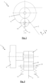
Fig. 2 diagrammatically shows a second embodiment of a yarn tensioning system according to the present invention in front view; -
Fig. 3 shows the yarn tensioning system fromFig. 2 in side view; -
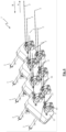
Fig. 4 shows a third embodiment of a yarn tensioning system according to the present invention in front view, without yarn; -
Fig. 5 shows the yarn tensioning system fromFig. 4 partially in cutaway perspective view, without yarn; -
Fig. 6 shows the yarn tensioning system fromFig. 4 in perspective with yarn that is herewith tensioned.. - The figures show some examples of yarn tensioning systems (1) according to the present invention.
- These yarn tensioning systems (1) each comprise, for each yarn (2) to be tensioned, a brake roller (5) which is rotatably arranged and a motor (6) for supplying a torque to the brake roller (5).
- In the first embodiment illustrated in
Fig. 1 , a yarn (2) taken from a yarn storage system (3) in a first direction (A) to a yarn take-off system (4) of a weaving machine, or recuperated in a second direction (B), opposite to the first direction (A), between the brake roller (5) and the yarn take-off system (4), is wound several times around the brake roller (5) to limit slipping of the yarn (2) with respect to the brake roller (5). - In order to further limit slipping of the yarn (2) with respect to the brake roller (5), this yarn tensioning system (1) furthermore comprises a braking device (7) which is arranged between the yarn storage system (3) and the brake roller (5).
- In order to prevent the yarn (2) from running off the brake roller (5), the brake roller (5) is provided with flanges (9) which limit the running surface (8) for the yarn (2). The running surface (8) of this brake roller (5) may be provided with an anti-slip layer by coating it, for example with rubber.
- In the second embodiment, which is illustrated in
Figs. 2 and 3 , the yarn tensioning system (1) comprises a tension roller (10). In order to limit slipping of the yarn (2) with respect to the brake roller (5), springs (11) push the shaft (12) of this tension roller (10) towards the brake roller (5), so that the tension roller (10) is arranged in a clamped manner against the brake roller (5) to clamp the yarn (2) between the brake roller (5) and the tension roller (10). - In the third embodiment, which is illustrated in
Figs. 4 to 6 , the yarn tensioning system (1) is configured to keep 8 yarns (2) under tension. These yarns (2) may be, for example, warp threads (2) which are fed to a carpet weaving machine as yarn take-off system (4). To this end, the yarn tensioning system (1) comprises a brake roller (5), a motor (6) and a tension roller (10) as in the second embodiment for each yarn (2). For the sake of clarity of the figures, only one motor (6) is shown. Each yarn (2) is fed through a holder (15) via a corresponding tubular guide (14) and is passed to the corresponding brake roller (5) via a funnel-shaped guide (13), wound around this brake roller (5) and fed to the yarn take-off system in a first direction (A) through an eyelet (17). The outlet opening (16) of the tubular guide (14) is smaller than the inlet opening to the funnel-shaped guide (13). The funnel-shaped guide (13) comprises a cup-shaped cavity in which the yarn (2) is collected in the case of yarn recuperation in a second direction (B). - In all illustrated embodiments, the motor (6) is a pancake motor (6) which is configured to supply a torque to the brake roller (5). On the one hand, the motor (6) is actuated in generator operation to keep the yarn (2) under tension. On the other hand, the motor (6) is actuated in motor operation to recuperate the yarn (2) between the brake roller (5) and the yarn take-off system (4) in a second direction (B), which is opposite to the first direction (A).
- The yarn tensioning systems (1) comprise a central control unit (not shown) and means for immediately making the energy generated during the generator operation of the motor (6) available to this central control unit of the yarn tensioning system (1). Alternatively, the yarn tensioning systems (1) could comprise means for storing energy generated during the generator operation of the motor (6), so that during the motor operation of the motor (6), the motor (6) is driven by means of the stored energy.
- Preferably, the yarn tensioning systems (1) also comprise a tension measuring device (not shown) for measuring the yarn tension. This measured yarn tension is then communicated to actuating means for actuating the motor (6), preferably by means of communication means, so that this motor (6) can be actuated on the basis thereof. In addition, the yarn tensioning systems (1) may comprise indicating means for generating a signal with regard to the measured yarn tension and communication means for communicating the measured yarn tension of the tension measuring device to these indicating means.
- By means of the speed of the motor (6) and the diameter of the brake roller (5), the length of the yarn (2) which is taken off by the yarn take-off system (4) can be easily determined.
Claims (14)
- Yarn tensioning system (1) for keeping at least one yarn (2) which is taken from a yarn storage system (3) in a first direction (A) to a yarn take-off system (4) of a weaving machine under tension, comprising a brake roller (5) which is rotatably arranged in the yarn tensioning system (1) and around which the yarn (2) is at least partially wound in order to keep this yarn (2) under tension between the brake roller (5) and the yarn take-off system (4), wherein the yarn tensioning system (1) comprises a motor (6) for supplying a torque to the brake roller (5), in which this motor (6) is actuable in generator operation to keep the yarn (2) under tension and wherein the motor (6) is actuable in motor operation to recuperate the yarn (2) between the brake roller (5) and the yarn take-off system (4) in a second direction (B) which is opposite to the first direction (A) characterized in that the yarn tensioning system (1) comprises a funnel-shaped guide (13) for guiding the yarn (2) to the brake roller (5) and comprises a tubular guide (14) for guiding the yarn (2) to the funnel-shaped guide (13).
- Yarn tensioning system (1) according to claim 1, characterized in that the motor (6) is individually actuable.
- Yarn tensioning system (1) according to one of the preceding claims, characterized in that the yarn tensioning system (1) comprises means for storing the energy generated during the generator operation of the motor (6), so that the motor (6) is driven by the stored energy during the motor operation of the motor (6).
- Yarn tensioning system (1) according to one of the preceding claims, characterized in that the yarn tensioning system (1) comprises measuring means for determining the length of the yarn (2) which is taken off by the yarn take-off system (4).
- Yarn tensioning system (1) according to one of the preceding claims, characterized in that the yarn tensioning system (1) comprises time monitoring means to keep track of the time during which the motor (6) operates in motor operation to recuperate the yarn (2) and to compare this monitored time with a certain reference value.
- Yarn tensioning system (1) according to one of the preceding claims, characterized in that the yarn tensioning system (1) comprises communication means for receiving signals from the yarn take-off system (4) with regard to the operation of the yarn take-off system (4), comprises measuring means for measuring parameters for the operation of the yarn tensioning system (1) and comprises tension monitoring means for monitoring the parameters for the operation of the yarn tensioning system (1) relative to the received signals of the yarn take-off system (4).
- Yarn tensioning system (1) according to one of the preceding claims, characterized in that the yarn tensioning system (1) comprises a tension measuring device for measuring the yarn tension.
- Yarn tensioning system (1) according to Claim 7, characterized in that the yarn tensioning system (1) comprises actuating means for actuating the motor (6) on the basis of the yarn tension measured using the tension measuring device and communication means for communicating the measured yarn tension from the tension measuring device to the actuating means.
- Yarn tensioning system (1) according to one of the preceding claims, characterized in that the yarn tensioning system (1) comprises a said brake roller (5) and a said motor (6) for each yarn (2) taken from the yarn storage system (3).
- Yarn tensioning system (1) according to one of the preceding claims, characterized in that the yarn tensioning system (1) comprises a tension roller (10) which is arranged in a clamped manner against the brake roller (5) in the yarn tensioning system (1) to clamp the yarn (2) between the brake roller (5) and the tension roller (10).
- Yarn tensioning system (1) according to one of the preceding claims, characterized in that the brake roller (5) is provided for winding the yarn (2) several times around it.
- Yarn tensioning system (1) according to one of the preceding claims, characterized in that the yarn tensioning system (1) comprises a braking device (7) for braking the yarn (2) in order to prevent the yarn (2) from slipping on the brake roller (5).
- Yarn tensioning system (1) according to one of the preceding claims, characterized in that the brake roller (5) comprises a running surface for at least partially winding the yarn (2) around it, in which said running surface is provided with an anti-slip layer and/or with a profiling.
- Weaving machine, comprising a yarn storage system (3), a yarn take-off system (4) for taking yarn (2) from the yarn storage system (3) and a yarn tensioning system (1) to keep a yarn (2) which has been taken from the yarn storage system (3) by the yarn take-off system (4) under tension between the yarn tensioning system (1) and the yarn take-off system (4), characterized in that the yarn tensioning system (1) is a yarn tensioning system (1) according to one of the preceding claims.
Applications Claiming Priority (3)
| Application Number | Priority Date | Filing Date | Title |
|---|---|---|---|
| BE2015/5716A BE1023564B1 (en) | 2015-11-03 | 2015-11-03 | YARN TENSION SYSTEM AND METHOD FOR TENSIONING A YARN TAKEN FROM A YARN STORAGE SYSTEM TO A YARN REMOVAL SYSTEM OF A WEAVING MACHINE |
| PCT/IB2016/056580 WO2017077454A1 (en) | 2015-11-03 | 2016-11-02 | Yarn tensioning system and method for keeping a yarn which is taken from a yarn storage system to a yarn take-off system of a weaving machine under tension |
| EP16806283.4A EP3371082B1 (en) | 2015-11-03 | 2016-11-02 | Yarn tensioning system and method for keeping a yarn which is taken from a yarn storage system to a yarn take-off system of a weaving machine under tension |
Related Parent Applications (2)
| Application Number | Title | Priority Date | Filing Date |
|---|---|---|---|
| EP16806283.4A Division EP3371082B1 (en) | 2015-11-03 | 2016-11-02 | Yarn tensioning system and method for keeping a yarn which is taken from a yarn storage system to a yarn take-off system of a weaving machine under tension |
| EP16806283.4A Division-Into EP3371082B1 (en) | 2015-11-03 | 2016-11-02 | Yarn tensioning system and method for keeping a yarn which is taken from a yarn storage system to a yarn take-off system of a weaving machine under tension |
Publications (3)
| Publication Number | Publication Date |
|---|---|
| EP3842371A1 EP3842371A1 (en) | 2021-06-30 |
| EP3842371B1 true EP3842371B1 (en) | 2023-06-07 |
| EP3842371C0 EP3842371C0 (en) | 2023-06-07 |
Family
ID=55237453
Family Applications (2)
| Application Number | Title | Priority Date | Filing Date |
|---|---|---|---|
| EP21150976.5A Active EP3842371B1 (en) | 2015-11-03 | 2016-11-02 | Yarn tensioning system for keeping a yarn which is taken from a yarn storage system to a yarn take-off system of a weaving machine under tension |
| EP16806283.4A Active EP3371082B1 (en) | 2015-11-03 | 2016-11-02 | Yarn tensioning system and method for keeping a yarn which is taken from a yarn storage system to a yarn take-off system of a weaving machine under tension |
Family Applications After (1)
| Application Number | Title | Priority Date | Filing Date |
|---|---|---|---|
| EP16806283.4A Active EP3371082B1 (en) | 2015-11-03 | 2016-11-02 | Yarn tensioning system and method for keeping a yarn which is taken from a yarn storage system to a yarn take-off system of a weaving machine under tension |
Country Status (8)
| Country | Link |
|---|---|
| US (1) | US10633213B2 (en) |
| EP (2) | EP3842371B1 (en) |
| CN (2) | CN112875428B (en) |
| BE (1) | BE1023564B1 (en) |
| DK (1) | DK3371082T3 (en) |
| PL (2) | PL3371082T3 (en) |
| PT (1) | PT3371082T (en) |
| WO (1) | WO2017077454A1 (en) |
Families Citing this family (13)
| Publication number | Priority date | Publication date | Assignee | Title |
|---|---|---|---|---|
| BE1023564B1 (en) * | 2015-11-03 | 2017-05-05 | VAN DE WIELE Michel NV | YARN TENSION SYSTEM AND METHOD FOR TENSIONING A YARN TAKEN FROM A YARN STORAGE SYSTEM TO A YARN REMOVAL SYSTEM OF A WEAVING MACHINE |
| US11130652B2 (en) * | 2018-05-03 | 2021-09-28 | Nv Michel Van De Wiele | Yarn tensioning system and method for keeping a yarn which is taken from a yarn storage system to a yarn take-off system of a weaving machine under tension |
| BE1026405B1 (en) | 2018-06-20 | 2020-01-30 | Nv Michel Van De Wiele | YARN STOCK DEVICE FOR A YARN PROCESSING MACHINE |
| BE1027254B1 (en) | 2019-05-04 | 2020-12-07 | Vandewiele Nv | Method for replenishing yarn supplies in a yarn supply device of a textile machine and a yarn supply device provided for this purpose |
| BE1027382B1 (en) | 2019-06-20 | 2021-01-28 | Vandewiele Nv | An arrangement of a weaving machine and a yarn supply device with an associated yarn tension device |
| BE1027386B1 (en) | 2019-06-20 | 2021-01-27 | Vandewiele Nv | Weaving method with regulation or control of the yarn tension in warp threads and weaving machine for producing a fabric according to this weaving method |
| BE1027383B1 (en) | 2019-06-20 | 2021-01-28 | Vandewiele Nv | DEVICE AND METHOD FOR DETECTING DEVIATIONS IN POLAR FORMATION IN A LIFE |
| CN110498293B (en) * | 2019-08-23 | 2020-07-28 | 西安交通大学 | Temperature-adjustable anti-sticking pre-impregnated tow tension-reducing conveying device |
| CN111020820A (en) * | 2019-12-11 | 2020-04-17 | 嘉兴市中嘉纺织有限公司 | Let-off device of rapier loom |
| US11565907B2 (en) | 2020-08-06 | 2023-01-31 | Columbia Insurance Company | Methods and devices for transporting yarn |
| CN112173871B (en) * | 2020-10-30 | 2022-05-03 | 诸暨市锦依渝纺织科技有限公司 | Yarn guide for textile machinery |
| CN112340530B (en) * | 2020-11-06 | 2022-05-31 | 顺鹏塑胶(苏州)有限公司 | Manufacturing method of automatic loose reel winder |
| EP4310044A1 (en) * | 2022-07-20 | 2024-01-24 | Savio Macchine Tessili S.p.A. | Winding unit provided with a thread tensioning device of a yarn, and the related control method |
Family Cites Families (25)
| Publication number | Priority date | Publication date | Assignee | Title |
|---|---|---|---|---|
| US1956631A (en) * | 1929-08-19 | 1934-05-01 | Gen Cable Corp | Unwinding device |
| US2048511A (en) * | 1934-07-19 | 1936-07-21 | Western Electric Co | Strand handling apparatus |
| GB603308A (en) * | 1945-10-10 | 1948-06-14 | Mellor Bromley & Co Ltd | Improvements in or relating to yarn or thread tensioning devices |
| US2668019A (en) * | 1949-07-07 | 1954-02-02 | Western Electric Co | Strand tension control mechanism |
| US2764367A (en) * | 1955-09-27 | 1956-09-25 | Fielderest Mills Inc | Tension and let-off device and method |
| FR2145056A5 (en) * | 1971-07-07 | 1973-02-16 | Inst Textile De France | Yarn tensioning device - including yarn tensioning roller connected to generator rotor |
| BE1009386A3 (en) * | 1995-05-11 | 1997-03-04 | Michel Van De Wiele N V | COMBINED CONTROL AND DONOR POOL POOL POOL LOOMS FOR CHAIN TREE indulgence. |
| IT1282898B1 (en) * | 1995-09-20 | 1998-04-01 | Mario Gallo | DEVICE TO CONTROL THE THREAD TENSION. |
| BE1009719A3 (en) * | 1995-10-24 | 1997-07-01 | Wiele Michel Van De Nv | System under power market under chain wires on a tree stand. |
| BE1012782A3 (en) * | 1999-07-12 | 2001-03-06 | Wiele Michel Van De Nv | DEVICE FOR TENSION AND PULLING OUT FROM a weaving frame loom HEADED TO A CHAIN WIRES. |
| BE1014308A5 (en) * | 2001-07-20 | 2003-08-05 | Wiele Michel Van De Nv | METHOD AND DEVICE FOR CONTROLLING A winding device. |
| GB2378188B (en) | 2001-07-28 | 2005-03-30 | Griffith Textile Mach Ltd | A creel |
| GB2427621A (en) | 2005-06-24 | 2007-01-03 | Griffith Textile Mach Ltd | A method and apparatus for controlling yarn tension |
| GB2428921B (en) | 2005-08-01 | 2007-12-27 | Roke Manor Research | Sharing spectrum between radar and communications applications |
| DE102005045789A1 (en) * | 2005-09-24 | 2007-03-29 | Saurer Gmbh & Co. Kg | Method for operating a workstation of a textile machine producing cross-wound bobbins |
| EP1870364A1 (en) * | 2006-06-23 | 2007-12-26 | Benninger AG | Thread tightener and device and method for operating a creel |
| GB2442955A (en) | 2006-10-19 | 2008-04-23 | Griffith Textile Mach Ltd | Yarn tension control mechanism |
| ITBO20080551A1 (en) * | 2008-09-11 | 2010-03-12 | S I M A Societa Ind Meccani Che Affini A R | MACHINE FOR YARNING OF YARNS USED AS A TORCH OR AS A ROPE |
| EP2192071B1 (en) * | 2008-11-29 | 2011-08-17 | Karl Mayer Textilmaschinenfabrik GmbH | Thread tension device |
| EP2192072B1 (en) * | 2008-11-29 | 2015-05-06 | Karl Mayer Textilmaschinenfabrik GmbH | Device to set the tension of a thread |
| BE1019155A3 (en) * | 2010-01-15 | 2012-04-03 | Wiele Michel Van De Nv | METHOD AND APPARATUS FOR MANUFACTURING TISSUES WITH AT LEAST TWO DIFFERENT POOL HEIGHTS IN A SAME POOL ROW |
| ITTO20120261A1 (en) * | 2012-03-22 | 2013-09-23 | Lgl Electronics Spa | METHOD OF FEEDING / RECOVERY OF YARN FOR TEXTILE MACHINES, AND APPARATUS FOR THE EXECUTION OF THIS METHOD. |
| ITTO20130875A1 (en) * | 2013-10-29 | 2015-04-30 | Lgl Electronics Spa | POSITIVE YARN FEEDER WITH CONTROL OF POWER SUPPLY VOLTAGE. |
| CN204124947U (en) * | 2014-09-30 | 2015-01-28 | 张仁晓 | Length of cable determinator |
| BE1023564B1 (en) * | 2015-11-03 | 2017-05-05 | VAN DE WIELE Michel NV | YARN TENSION SYSTEM AND METHOD FOR TENSIONING A YARN TAKEN FROM A YARN STORAGE SYSTEM TO A YARN REMOVAL SYSTEM OF A WEAVING MACHINE |
-
2015
- 2015-11-03 BE BE2015/5716A patent/BE1023564B1/en not_active IP Right Cessation
-
2016
- 2016-11-02 EP EP21150976.5A patent/EP3842371B1/en active Active
- 2016-11-02 EP EP16806283.4A patent/EP3371082B1/en active Active
- 2016-11-02 PT PT168062834T patent/PT3371082T/en unknown
- 2016-11-02 WO PCT/IB2016/056580 patent/WO2017077454A1/en active Application Filing
- 2016-11-02 CN CN202110067474.8A patent/CN112875428B/en active Active
- 2016-11-02 PL PL16806283T patent/PL3371082T3/en unknown
- 2016-11-02 DK DK16806283.4T patent/DK3371082T3/en active
- 2016-11-02 CN CN201680063913.5A patent/CN108349680B/en active Active
- 2016-11-02 US US15/773,557 patent/US10633213B2/en active Active
- 2016-11-02 PL PL21150976.5T patent/PL3842371T3/en unknown
Also Published As
| Publication number | Publication date |
|---|---|
| WO2017077454A1 (en) | 2017-05-11 |
| PL3371082T3 (en) | 2021-09-13 |
| US10633213B2 (en) | 2020-04-28 |
| CN108349680A (en) | 2018-07-31 |
| CN108349680B (en) | 2021-02-02 |
| BE1023564B1 (en) | 2017-05-05 |
| DK3371082T3 (en) | 2021-03-15 |
| BE1023564A1 (en) | 2017-05-05 |
| CN112875428A (en) | 2021-06-01 |
| EP3842371A1 (en) | 2021-06-30 |
| CN112875428B (en) | 2022-11-01 |
| EP3371082B1 (en) | 2021-02-17 |
| WO2017077454A9 (en) | 2017-07-06 |
| PT3371082T (en) | 2021-03-16 |
| US20180319618A1 (en) | 2018-11-08 |
| PL3842371T3 (en) | 2023-07-31 |
| EP3371082A1 (en) | 2018-09-12 |
| EP3842371C0 (en) | 2023-06-07 |
Similar Documents
| Publication | Publication Date | Title |
|---|---|---|
| EP3842371B1 (en) | Yarn tensioning system for keeping a yarn which is taken from a yarn storage system to a yarn take-off system of a weaving machine under tension | |
| JP4956667B2 (en) | Filament combination method and filament mixture produced thereby | |
| JP6002125B2 (en) | Improved method and apparatus for feeding a thread or filament to a processing machine with constant tension and speed | |
| EP1991726B1 (en) | Improved device for feeding thread or yarn to a textile machine and a method for implementing the feed | |
| JP6002214B2 (en) | Method and apparatus for feeding yarn to a textile machine with constant tension and constant speed or quantity | |
| EP2868609B1 (en) | Yarn supplying system | |
| CN113924391B (en) | Weaving method for controlling or regulating yarn tension in warp yarn and loom for producing fabric using the weaving method | |
| WO2011145415A1 (en) | Thread supply system | |
| US11130652B2 (en) | Yarn tensioning system and method for keeping a yarn which is taken from a yarn storage system to a yarn take-off system of a weaving machine under tension | |
| CZ2011589A3 (en) | Method of and apparatus for determining surface wear of textile machine components by a moving linear textile material | |
| US20220220643A1 (en) | An arrangement of a weaving machine and a yarn storage device with an associated yarn-tensioning device | |
| CN105297197A (en) | Spinning machine and spinning method | |
| US2764367A (en) | Tension and let-off device and method | |
| CN1208510C (en) | Method for inserting elastomeric yarn and yarn processing system | |
| EP3374303B1 (en) | Controlled system for supplying weft yarn in a loom | |
| CN111691049A (en) | Yarn treatment process and device | |
| CN117622945A (en) | Method for controlled winding of textile product on textile machine and textile machine | |
| WO2020225705A1 (en) | Method for replenishing yarn supplies in a yarn storage device of a textile machine and a yarn storage device provided for this | |
| RU2021106189A (en) | DEVICE FOR MANUFACTURING WOVEN CASING | |
| KR100947500B1 (en) | Bundle of industrial synthetic filament used in covering optic fiber | |
| CN108350616A (en) | Method for monitoring the quality during weaving and Weaving device | |
| ITVC960007A1 (en) | DEVICE AND METHOD FOR CHECKING AND DRASTICALLY REDUCING THE VARIOUS TENSION TENSIONS OF A THREAD IN A SPOOL SPOOLER IN |
Legal Events
| Date | Code | Title | Description |
|---|---|---|---|
| PUAI | Public reference made under article 153(3) epc to a published international application that has entered the european phase |
Free format text: ORIGINAL CODE: 0009012 |
|
| STAA | Information on the status of an ep patent application or granted ep patent |
Free format text: STATUS: THE APPLICATION HAS BEEN PUBLISHED |
|
| AC | Divisional application: reference to earlier application |
Ref document number: 3371082 Country of ref document: EP Kind code of ref document: P |
|
| AK | Designated contracting states |
Kind code of ref document: A1 Designated state(s): AL AT BE BG CH CY CZ DE DK EE ES FI FR GB GR HR HU IE IS IT LI LT LU LV MC MK MT NL NO PL PT RO RS SE SI SK SM TR |
|
| STAA | Information on the status of an ep patent application or granted ep patent |
Free format text: STATUS: REQUEST FOR EXAMINATION WAS MADE |
|
| 17P | Request for examination filed |
Effective date: 20210816 |
|
| RBV | Designated contracting states (corrected) |
Designated state(s): AL AT BE BG CH CY CZ DE DK EE ES FI FR GB GR HR HU IE IS IT LI LT LU LV MC MK MT NL NO PL PT RO RS SE SI SK SM TR |
|
| GRAP | Despatch of communication of intention to grant a patent |
Free format text: ORIGINAL CODE: EPIDOSNIGR1 |
|
| STAA | Information on the status of an ep patent application or granted ep patent |
Free format text: STATUS: GRANT OF PATENT IS INTENDED |
|
| INTG | Intention to grant announced |
Effective date: 20221108 |
|
| GRAS | Grant fee paid |
Free format text: ORIGINAL CODE: EPIDOSNIGR3 |
|
| GRAA | (expected) grant |
Free format text: ORIGINAL CODE: 0009210 |
|
| STAA | Information on the status of an ep patent application or granted ep patent |
Free format text: STATUS: THE PATENT HAS BEEN GRANTED |
|
| AC | Divisional application: reference to earlier application |
Ref document number: 3371082 Country of ref document: EP Kind code of ref document: P |
|
| AK | Designated contracting states |
Kind code of ref document: B1 Designated state(s): AL AT BE BG CH CY CZ DE DK EE ES FI FR GB GR HR HU IE IS IT LI LT LU LV MC MK MT NL NO PL PT RO RS SE SI SK SM TR |
|
| REG | Reference to a national code |
Ref country code: GB Ref legal event code: FG4D |
|
| REG | Reference to a national code |
Ref country code: CH Ref legal event code: EP Ref country code: AT Ref legal event code: REF Ref document number: 1574485 Country of ref document: AT Kind code of ref document: T Effective date: 20230615 Ref country code: DE Ref legal event code: R096 Ref document number: 602016080285 Country of ref document: DE |
|
| U01 | Request for unitary effect filed |
Effective date: 20230607 |
|
| U07 | Unitary effect registered |
Designated state(s): AT BE BG DE DK EE FI FR IT LT LU LV MT NL PT SE SI Effective date: 20230612 |
|
| REG | Reference to a national code |
Ref country code: LT Ref legal event code: MG9D |
|
| PG25 | Lapsed in a contracting state [announced via postgrant information from national office to epo] |
Ref country code: NO Free format text: LAPSE BECAUSE OF FAILURE TO SUBMIT A TRANSLATION OF THE DESCRIPTION OR TO PAY THE FEE WITHIN THE PRESCRIBED TIME-LIMIT Effective date: 20230907 Ref country code: ES Free format text: LAPSE BECAUSE OF FAILURE TO SUBMIT A TRANSLATION OF THE DESCRIPTION OR TO PAY THE FEE WITHIN THE PRESCRIBED TIME-LIMIT Effective date: 20230607 |
|
| PG25 | Lapsed in a contracting state [announced via postgrant information from national office to epo] |
Ref country code: RS Free format text: LAPSE BECAUSE OF FAILURE TO SUBMIT A TRANSLATION OF THE DESCRIPTION OR TO PAY THE FEE WITHIN THE PRESCRIBED TIME-LIMIT Effective date: 20230607 Ref country code: HR Free format text: LAPSE BECAUSE OF FAILURE TO SUBMIT A TRANSLATION OF THE DESCRIPTION OR TO PAY THE FEE WITHIN THE PRESCRIBED TIME-LIMIT Effective date: 20230607 Ref country code: GR Free format text: LAPSE BECAUSE OF FAILURE TO SUBMIT A TRANSLATION OF THE DESCRIPTION OR TO PAY THE FEE WITHIN THE PRESCRIBED TIME-LIMIT Effective date: 20230908 |
|
| U20 | Renewal fee paid [unitary effect] |
Year of fee payment: 8 Effective date: 20231123 |
|
| PG25 | Lapsed in a contracting state [announced via postgrant information from national office to epo] |
Ref country code: SK Free format text: LAPSE BECAUSE OF FAILURE TO SUBMIT A TRANSLATION OF THE DESCRIPTION OR TO PAY THE FEE WITHIN THE PRESCRIBED TIME-LIMIT Effective date: 20230607 |
|
| PGFP | Annual fee paid to national office [announced via postgrant information from national office to epo] |
Ref country code: GB Payment date: 20231123 Year of fee payment: 8 |
|
| PG25 | Lapsed in a contracting state [announced via postgrant information from national office to epo] |
Ref country code: IS Free format text: LAPSE BECAUSE OF FAILURE TO SUBMIT A TRANSLATION OF THE DESCRIPTION OR TO PAY THE FEE WITHIN THE PRESCRIBED TIME-LIMIT Effective date: 20231007 |
|
| PG25 | Lapsed in a contracting state [announced via postgrant information from national office to epo] |
Ref country code: SM Free format text: LAPSE BECAUSE OF FAILURE TO SUBMIT A TRANSLATION OF THE DESCRIPTION OR TO PAY THE FEE WITHIN THE PRESCRIBED TIME-LIMIT Effective date: 20230607 Ref country code: SK Free format text: LAPSE BECAUSE OF FAILURE TO SUBMIT A TRANSLATION OF THE DESCRIPTION OR TO PAY THE FEE WITHIN THE PRESCRIBED TIME-LIMIT Effective date: 20230607 Ref country code: RO Free format text: LAPSE BECAUSE OF FAILURE TO SUBMIT A TRANSLATION OF THE DESCRIPTION OR TO PAY THE FEE WITHIN THE PRESCRIBED TIME-LIMIT Effective date: 20230607 Ref country code: IS Free format text: LAPSE BECAUSE OF FAILURE TO SUBMIT A TRANSLATION OF THE DESCRIPTION OR TO PAY THE FEE WITHIN THE PRESCRIBED TIME-LIMIT Effective date: 20231007 Ref country code: CZ Free format text: LAPSE BECAUSE OF FAILURE TO SUBMIT A TRANSLATION OF THE DESCRIPTION OR TO PAY THE FEE WITHIN THE PRESCRIBED TIME-LIMIT Effective date: 20230607 |
|
| PGFP | Annual fee paid to national office [announced via postgrant information from national office to epo] |
Ref country code: TR Payment date: 20231030 Year of fee payment: 8 |
|
| PGFP | Annual fee paid to national office [announced via postgrant information from national office to epo] |
Ref country code: PL Payment date: 20231020 Year of fee payment: 8 |
|
| PLBE | No opposition filed within time limit |
Free format text: ORIGINAL CODE: 0009261 |
|
| STAA | Information on the status of an ep patent application or granted ep patent |
Free format text: STATUS: NO OPPOSITION FILED WITHIN TIME LIMIT |