EP3842316A1 - Method and device for controlling operation of self-driving car - Google Patents
Method and device for controlling operation of self-driving car Download PDFInfo
- Publication number
- EP3842316A1 EP3842316A1 EP20198348.3A EP20198348A EP3842316A1 EP 3842316 A1 EP3842316 A1 EP 3842316A1 EP 20198348 A EP20198348 A EP 20198348A EP 3842316 A1 EP3842316 A1 EP 3842316A1
- Authority
- EP
- European Patent Office
- Prior art keywords
- crosswalk
- time
- electronic device
- sdc
- interval
- Prior art date
- Legal status (The legal status is an assumption and is not a legal conclusion. Google has not performed a legal analysis and makes no representation as to the accuracy of the status listed.)
- Granted
Links
- 238000000034 method Methods 0.000 title claims abstract description 81
- 230000033001 locomotion Effects 0.000 claims abstract description 58
- 238000013459 approach Methods 0.000 claims abstract description 37
- 239000000872 buffer Substances 0.000 claims description 36
- 230000002123 temporal effect Effects 0.000 claims description 28
- 230000004044 response Effects 0.000 claims description 15
- 238000005516 engineering process Methods 0.000 description 96
- 238000004891 communication Methods 0.000 description 23
- 238000003860 storage Methods 0.000 description 17
- 230000008569 process Effects 0.000 description 16
- 230000006870 function Effects 0.000 description 7
- 230000004048 modification Effects 0.000 description 7
- 238000012986 modification Methods 0.000 description 7
- 238000001514 detection method Methods 0.000 description 5
- 238000010586 diagram Methods 0.000 description 5
- 230000001133 acceleration Effects 0.000 description 4
- 230000001960 triggered effect Effects 0.000 description 3
- 238000004364 calculation method Methods 0.000 description 2
- 230000000694 effects Effects 0.000 description 2
- 230000001788 irregular Effects 0.000 description 2
- 230000004807 localization Effects 0.000 description 2
- 239000012092 media component Substances 0.000 description 2
- 239000002245 particle Substances 0.000 description 2
- 238000012545 processing Methods 0.000 description 2
- 101100175317 Danio rerio gdf6a gene Proteins 0.000 description 1
- 230000003044 adaptive effect Effects 0.000 description 1
- 239000000443 aerosol Substances 0.000 description 1
- 230000008859 change Effects 0.000 description 1
- 238000004590 computer program Methods 0.000 description 1
- 230000001627 detrimental effect Effects 0.000 description 1
- 238000009826 distribution Methods 0.000 description 1
- 239000000446 fuel Substances 0.000 description 1
- 238000003384 imaging method Methods 0.000 description 1
- 230000014759 maintenance of location Effects 0.000 description 1
- 238000004519 manufacturing process Methods 0.000 description 1
- 238000005259 measurement Methods 0.000 description 1
- 239000007787 solid Substances 0.000 description 1
- 230000007704 transition Effects 0.000 description 1
Images


Classifications
-
- B—PERFORMING OPERATIONS; TRANSPORTING
- B60—VEHICLES IN GENERAL
- B60W—CONJOINT CONTROL OF VEHICLE SUB-UNITS OF DIFFERENT TYPE OR DIFFERENT FUNCTION; CONTROL SYSTEMS SPECIALLY ADAPTED FOR HYBRID VEHICLES; ROAD VEHICLE DRIVE CONTROL SYSTEMS FOR PURPOSES NOT RELATED TO THE CONTROL OF A PARTICULAR SUB-UNIT
- B60W30/00—Purposes of road vehicle drive control systems not related to the control of a particular sub-unit, e.g. of systems using conjoint control of vehicle sub-units, or advanced driver assistance systems for ensuring comfort, stability and safety or drive control systems for propelling or retarding the vehicle
- B60W30/18—Propelling the vehicle
- B60W30/18009—Propelling the vehicle related to particular drive situations
- B60W30/18154—Approaching an intersection
-
- B—PERFORMING OPERATIONS; TRANSPORTING
- B60—VEHICLES IN GENERAL
- B60W—CONJOINT CONTROL OF VEHICLE SUB-UNITS OF DIFFERENT TYPE OR DIFFERENT FUNCTION; CONTROL SYSTEMS SPECIALLY ADAPTED FOR HYBRID VEHICLES; ROAD VEHICLE DRIVE CONTROL SYSTEMS FOR PURPOSES NOT RELATED TO THE CONTROL OF A PARTICULAR SUB-UNIT
- B60W30/00—Purposes of road vehicle drive control systems not related to the control of a particular sub-unit, e.g. of systems using conjoint control of vehicle sub-units, or advanced driver assistance systems for ensuring comfort, stability and safety or drive control systems for propelling or retarding the vehicle
- B60W30/18—Propelling the vehicle
- B60W30/18009—Propelling the vehicle related to particular drive situations
- B60W30/181—Preparing for stopping
-
- B—PERFORMING OPERATIONS; TRANSPORTING
- B60—VEHICLES IN GENERAL
- B60K—ARRANGEMENT OR MOUNTING OF PROPULSION UNITS OR OF TRANSMISSIONS IN VEHICLES; ARRANGEMENT OR MOUNTING OF PLURAL DIVERSE PRIME-MOVERS IN VEHICLES; AUXILIARY DRIVES FOR VEHICLES; INSTRUMENTATION OR DASHBOARDS FOR VEHICLES; ARRANGEMENTS IN CONNECTION WITH COOLING, AIR INTAKE, GAS EXHAUST OR FUEL SUPPLY OF PROPULSION UNITS IN VEHICLES
- B60K31/00—Vehicle fittings, acting on a single sub-unit only, for automatically controlling vehicle speed, i.e. preventing speed from exceeding an arbitrarily established velocity or maintaining speed at a particular velocity, as selected by the vehicle operator
-
- B—PERFORMING OPERATIONS; TRANSPORTING
- B60—VEHICLES IN GENERAL
- B60W—CONJOINT CONTROL OF VEHICLE SUB-UNITS OF DIFFERENT TYPE OR DIFFERENT FUNCTION; CONTROL SYSTEMS SPECIALLY ADAPTED FOR HYBRID VEHICLES; ROAD VEHICLE DRIVE CONTROL SYSTEMS FOR PURPOSES NOT RELATED TO THE CONTROL OF A PARTICULAR SUB-UNIT
- B60W30/00—Purposes of road vehicle drive control systems not related to the control of a particular sub-unit, e.g. of systems using conjoint control of vehicle sub-units, or advanced driver assistance systems for ensuring comfort, stability and safety or drive control systems for propelling or retarding the vehicle
- B60W30/18—Propelling the vehicle
- B60W30/18009—Propelling the vehicle related to particular drive situations
- B60W30/18109—Braking
-
- B—PERFORMING OPERATIONS; TRANSPORTING
- B60—VEHICLES IN GENERAL
- B60W—CONJOINT CONTROL OF VEHICLE SUB-UNITS OF DIFFERENT TYPE OR DIFFERENT FUNCTION; CONTROL SYSTEMS SPECIALLY ADAPTED FOR HYBRID VEHICLES; ROAD VEHICLE DRIVE CONTROL SYSTEMS FOR PURPOSES NOT RELATED TO THE CONTROL OF A PARTICULAR SUB-UNIT
- B60W30/00—Purposes of road vehicle drive control systems not related to the control of a particular sub-unit, e.g. of systems using conjoint control of vehicle sub-units, or advanced driver assistance systems for ensuring comfort, stability and safety or drive control systems for propelling or retarding the vehicle
- B60W30/18—Propelling the vehicle
- B60W30/18009—Propelling the vehicle related to particular drive situations
- B60W30/18159—Traversing an intersection
-
- B—PERFORMING OPERATIONS; TRANSPORTING
- B60—VEHICLES IN GENERAL
- B60W—CONJOINT CONTROL OF VEHICLE SUB-UNITS OF DIFFERENT TYPE OR DIFFERENT FUNCTION; CONTROL SYSTEMS SPECIALLY ADAPTED FOR HYBRID VEHICLES; ROAD VEHICLE DRIVE CONTROL SYSTEMS FOR PURPOSES NOT RELATED TO THE CONTROL OF A PARTICULAR SUB-UNIT
- B60W60/00—Drive control systems specially adapted for autonomous road vehicles
- B60W60/001—Planning or execution of driving tasks
- B60W60/0015—Planning or execution of driving tasks specially adapted for safety
- B60W60/0017—Planning or execution of driving tasks specially adapted for safety of other traffic participants
-
- B—PERFORMING OPERATIONS; TRANSPORTING
- B60—VEHICLES IN GENERAL
- B60W—CONJOINT CONTROL OF VEHICLE SUB-UNITS OF DIFFERENT TYPE OR DIFFERENT FUNCTION; CONTROL SYSTEMS SPECIALLY ADAPTED FOR HYBRID VEHICLES; ROAD VEHICLE DRIVE CONTROL SYSTEMS FOR PURPOSES NOT RELATED TO THE CONTROL OF A PARTICULAR SUB-UNIT
- B60W60/00—Drive control systems specially adapted for autonomous road vehicles
- B60W60/001—Planning or execution of driving tasks
- B60W60/0027—Planning or execution of driving tasks using trajectory prediction for other traffic participants
- B60W60/00272—Planning or execution of driving tasks using trajectory prediction for other traffic participants relying on extrapolation of current movement
-
- B—PERFORMING OPERATIONS; TRANSPORTING
- B60—VEHICLES IN GENERAL
- B60W—CONJOINT CONTROL OF VEHICLE SUB-UNITS OF DIFFERENT TYPE OR DIFFERENT FUNCTION; CONTROL SYSTEMS SPECIALLY ADAPTED FOR HYBRID VEHICLES; ROAD VEHICLE DRIVE CONTROL SYSTEMS FOR PURPOSES NOT RELATED TO THE CONTROL OF A PARTICULAR SUB-UNIT
- B60W60/00—Drive control systems specially adapted for autonomous road vehicles
- B60W60/001—Planning or execution of driving tasks
- B60W60/0027—Planning or execution of driving tasks using trajectory prediction for other traffic participants
- B60W60/00276—Planning or execution of driving tasks using trajectory prediction for other traffic participants for two or more other traffic participants
-
- G—PHYSICS
- G01—MEASURING; TESTING
- G01C—MEASURING DISTANCES, LEVELS OR BEARINGS; SURVEYING; NAVIGATION; GYROSCOPIC INSTRUMENTS; PHOTOGRAMMETRY OR VIDEOGRAMMETRY
- G01C21/00—Navigation; Navigational instruments not provided for in groups G01C1/00 - G01C19/00
- G01C21/20—Instruments for performing navigational calculations
-
- G—PHYSICS
- G01—MEASURING; TESTING
- G01C—MEASURING DISTANCES, LEVELS OR BEARINGS; SURVEYING; NAVIGATION; GYROSCOPIC INSTRUMENTS; PHOTOGRAMMETRY OR VIDEOGRAMMETRY
- G01C21/00—Navigation; Navigational instruments not provided for in groups G01C1/00 - G01C19/00
- G01C21/26—Navigation; Navigational instruments not provided for in groups G01C1/00 - G01C19/00 specially adapted for navigation in a road network
- G01C21/34—Route searching; Route guidance
-
- G—PHYSICS
- G06—COMPUTING; CALCULATING OR COUNTING
- G06V—IMAGE OR VIDEO RECOGNITION OR UNDERSTANDING
- G06V20/00—Scenes; Scene-specific elements
- G06V20/50—Context or environment of the image
- G06V20/56—Context or environment of the image exterior to a vehicle by using sensors mounted on the vehicle
-
- G—PHYSICS
- G06—COMPUTING; CALCULATING OR COUNTING
- G06V—IMAGE OR VIDEO RECOGNITION OR UNDERSTANDING
- G06V40/00—Recognition of biometric, human-related or animal-related patterns in image or video data
- G06V40/10—Human or animal bodies, e.g. vehicle occupants or pedestrians; Body parts, e.g. hands
- G06V40/103—Static body considered as a whole, e.g. static pedestrian or occupant recognition
-
- G—PHYSICS
- G08—SIGNALLING
- G08G—TRAFFIC CONTROL SYSTEMS
- G08G1/00—Traffic control systems for road vehicles
- G08G1/16—Anti-collision systems
-
- B—PERFORMING OPERATIONS; TRANSPORTING
- B60—VEHICLES IN GENERAL
- B60W—CONJOINT CONTROL OF VEHICLE SUB-UNITS OF DIFFERENT TYPE OR DIFFERENT FUNCTION; CONTROL SYSTEMS SPECIALLY ADAPTED FOR HYBRID VEHICLES; ROAD VEHICLE DRIVE CONTROL SYSTEMS FOR PURPOSES NOT RELATED TO THE CONTROL OF A PARTICULAR SUB-UNIT
- B60W2552/00—Input parameters relating to infrastructure
- B60W2552/45—Pedestrian sidewalk
-
- B—PERFORMING OPERATIONS; TRANSPORTING
- B60—VEHICLES IN GENERAL
- B60W—CONJOINT CONTROL OF VEHICLE SUB-UNITS OF DIFFERENT TYPE OR DIFFERENT FUNCTION; CONTROL SYSTEMS SPECIALLY ADAPTED FOR HYBRID VEHICLES; ROAD VEHICLE DRIVE CONTROL SYSTEMS FOR PURPOSES NOT RELATED TO THE CONTROL OF A PARTICULAR SUB-UNIT
- B60W2552/00—Input parameters relating to infrastructure
- B60W2552/53—Road markings, e.g. lane marker or crosswalk
-
- B—PERFORMING OPERATIONS; TRANSPORTING
- B60—VEHICLES IN GENERAL
- B60W—CONJOINT CONTROL OF VEHICLE SUB-UNITS OF DIFFERENT TYPE OR DIFFERENT FUNCTION; CONTROL SYSTEMS SPECIALLY ADAPTED FOR HYBRID VEHICLES; ROAD VEHICLE DRIVE CONTROL SYSTEMS FOR PURPOSES NOT RELATED TO THE CONTROL OF A PARTICULAR SUB-UNIT
- B60W2554/00—Input parameters relating to objects
- B60W2554/40—Dynamic objects, e.g. animals, windblown objects
- B60W2554/402—Type
- B60W2554/4029—Pedestrians
-
- B—PERFORMING OPERATIONS; TRANSPORTING
- B60—VEHICLES IN GENERAL
- B60W—CONJOINT CONTROL OF VEHICLE SUB-UNITS OF DIFFERENT TYPE OR DIFFERENT FUNCTION; CONTROL SYSTEMS SPECIALLY ADAPTED FOR HYBRID VEHICLES; ROAD VEHICLE DRIVE CONTROL SYSTEMS FOR PURPOSES NOT RELATED TO THE CONTROL OF A PARTICULAR SUB-UNIT
- B60W2554/00—Input parameters relating to objects
- B60W2554/40—Dynamic objects, e.g. animals, windblown objects
- B60W2554/404—Characteristics
- B60W2554/4042—Longitudinal speed
-
- B—PERFORMING OPERATIONS; TRANSPORTING
- B60—VEHICLES IN GENERAL
- B60W—CONJOINT CONTROL OF VEHICLE SUB-UNITS OF DIFFERENT TYPE OR DIFFERENT FUNCTION; CONTROL SYSTEMS SPECIALLY ADAPTED FOR HYBRID VEHICLES; ROAD VEHICLE DRIVE CONTROL SYSTEMS FOR PURPOSES NOT RELATED TO THE CONTROL OF A PARTICULAR SUB-UNIT
- B60W2554/00—Input parameters relating to objects
- B60W2554/40—Dynamic objects, e.g. animals, windblown objects
- B60W2554/404—Characteristics
- B60W2554/4044—Direction of movement, e.g. backwards
Landscapes
- Engineering & Computer Science (AREA)
- Automation & Control Theory (AREA)
- Mechanical Engineering (AREA)
- Transportation (AREA)
- Radar, Positioning & Navigation (AREA)
- Remote Sensing (AREA)
- General Physics & Mathematics (AREA)
- Physics & Mathematics (AREA)
- Human Computer Interaction (AREA)
- Theoretical Computer Science (AREA)
- Multimedia (AREA)
- Chemical & Material Sciences (AREA)
- Combustion & Propulsion (AREA)
- Traffic Control Systems (AREA)
- Mobile Radio Communication Systems (AREA)
Abstract
Description
- The present technology relates to self-driving cars and, specifically, to a method of and a processor for controlling operation of a self-driving car.
- Several computer based navigation systems that are configured for aiding navigation and/or control of vehicle have been proposed and implemented in the prior art. These systems range from more basic map-aided localization based solutions - i.e. use of a computer system to assist a driver in navigating a route from a starting point to a destination point; to more complex ones - computer-assisted and/or driver-autonomous driving systems.
- Some of these systems are implemented as what is commonly known as a "cruise control" system. Within these systems, the computer system boarded on the vehicles maintains a user-set speed of the vehicle. Some of the cruise control system implement an "intelligent distance control" system, whereby the user can set up a distance to a potential car in front (such as, select a value expressed in a number of vehicles) and the computer system adjusts the speed of the vehicle at least in part based on the vehicle approaching the potential vehicle in front within the pre-defined distance. Some of the cruise control systems are further equipped with collision control system, which systems upon detection of the vehicle (or other obstacle) in front of the moving vehicle, slow down or stop the vehicle.
- Some of the more advanced system provide for a fully autonomous driving of the vehicle without direct control from the operator (i.e. the driver), so-called Self-Driving Cars (SDCs). A given SDC includes computer systems that can cause the SDC to accelerate, break, stop, change lane and self-park.
- One of the technical challenges in implementing the above computer systems is planning a SDC operation when approaching a crosswalk.
- It is an object of the present technology to ameliorate at least some of the inconveniences present in the prior art. Embodiments of the present technology may provide and/or broaden the scope of approaches to methods of achieving the aims and objects of the present technology.
- Developers of the present technology have appreciated at least one technical problem associated with the prior art approaches. It should be noted that, during an approach to a crosswalk by the SDC, the SDC may detect an object in proximity and is configured to make a "decision" on whether the object, or the SDC, has priority of way through that crosswalk. For example, the SDC may detect and identify the object via a unique ID and may perform a "decision-making process" for determining decision data to be associated with the unique ID of that object, and which decision data is indicative of whether the SDC or the object identified via that unique ID has priority of way. Based on this, operation-control data may be determined for complying with the decision. For example, if the decision indicates that the object has priority of way, the determined operation-control data may allow the SDC to slow down and stop before crossing the crosswalk, so as to let the object cross the crosswalk first.
- In some instances, at least one problem arises when, for some reason, the object is no longer identified by the same unique ID at separate instances during the approach of the SDC to the crosswalk. To better illustrate this, let it be assumed that at a moment T2, irrespective of the reason therefor, a given object is identified by a unique ID "ID2", which is different from the unique ID "ID1" of that given object at a moment T1. Hence, for all intents and purposes, the SDC appreciates the given object with the unique ID "ID2" at the moment T2 as a different object from the given object with the unique ID "ID1" at the moment T1. In such situations, the SDC may need to repeat the decision-making process for that given object with the unique ID "ID2", since the data representative of the decision that has been previously made is associated with a "different" object (given object with the unique ID "ID1" at the moment T1).
- Such re-calculation may be detrimental for many reasons. In a first instance, such re-calculation requires use of computational resources of an electronic device associated with the SDC, which can be otherwise better allocated for executing other tasks associated with controlling operation of the SDC. In a second instance, it should be noted that the timing of the decision-making process may also be of importance - that is, the earlier the decision is made on priority of way, the more time the electronic device has for safely controlling operation of the SDC.
- For at least the reasons presented above, developers of the present technology have devised methods and systems where the decision data determined at T1 is associated with an "object-inclusion zone" as opposed to being associated with the given object identifiable via ID1. As a result, even if the given object is identified via ID2 at T2, the electronic device associated with the SDC may access the result of the decision-making process performed at T1, instead of repeating it at T2 for the given object identifiable via ID2. Indeed, by assigning the decision data to the object-inclusion zone allows the electronic device to, in a sense, access "knowledge" regarding the priority of way between the SDC and any object in the object-inclusion zone that is identifiable by a different unique ID than the unique ID of an object based on which the decision data has been determined.
- Accessing the decision data associated with the object-inclusion zone at the moment T2, therefore, results in an effect of requiring less computational resources at the moment T2 - it is not necessary to repeat the decision-making process on the priority of way and/or to re-compute operation-control data for the SDC at the moment T2 and, instead, use the operation-control data that has been determined for the SDC at the moment T1.
- In a first broad aspect of the present technology, there is provided a computer-implemented method for controlling operation of a Self-Driving Car (SDC). The method is executable by an electronic device coupled to the SDC. The method comprises, at a first moment in time during an approach of the SDC to a crosswalk, identifying, by the electronic device, an object-inclusion zone in proximity to the crosswalk. The object-inclusion zone potentially includes objects that are to cross the crosswalk. The method comprises, at a first moment in time during an approach of the SDC to a crosswalk, determining, by the electronic device, presence of an object in the object-inclusion zone. The object is identifiable by a first unique ID. The method comprises, at a first moment in time during an approach of the SDC to a crosswalk, determining, by the electronic device, an interval of time for the object based on movement data of the object. The interval of time is indicative of a temporal window during which the object is estimated to be crossing the crosswalk. The method comprises, at a first moment in time during an approach of the SDC to a crosswalk, using, by the electronic device, the interval of time and movement data of the SDC for determining operation-control data for controlling operation of the SDC. The operation-control data is indicative of a decision on a priority of way through the crosswalk between the SDC and the object. The method comprises, at a first moment in time during an approach of the SDC to a crosswalk, assigning, by the electronic device, decision data to the object-inclusion zone indicative of the decision, such that the priority of way between the SDC and any other object identifiable by an other unique ID that is different from the first unique ID in the object-inclusion zone is same as between the SDC and the object.
- In some embodiments of the method, the method further comprises, at the first moment in time during the approach of the SDC to the crosswalk, triggering, by the electronic device, the SDC to operate in accordance with the operation-control data.
- In some embodiments of the method, the triggering comprises one of (i) triggering, by the electronic device, the SDC to stop at the crosswalk and allowing any object from the object-inclusion zone to cross the crosswalk, and (ii) triggering, by the electronic device, the SDC to pass through the crosswalk before any object from the object-inclusion zone crosses the crosswalk.
- In some embodiments of the method, the method further comprises, at the first moment in time during the approach of the SDC to the crosswalk, triggering, by the electronic device based on the operation-control data, the SDC to stop at the crosswalk and allowing any object from the object-inclusion zone to cross the crosswalk. The method further comprises, at a second moment in time while the SDC is stopped at the crosswalk, in response to any object from the object-inclusion zone exiting the object-inclusion zone and beginning crossing the crosswalk, assigning, by the electronic device, new decision data to the object-inclusion zone indicative of a new decision.
- In some embodiments of the method, in response to the any object from the object-inclusion zone exiting the object-inclusion zone and beginning crossing the crosswalk, the method further comprises determining, by the electronic device, presence of a second object in the object-inclusion zone. The second object is identifiable by a second unique ID. In response to the any object from the object-inclusion zone exiting the object-inclusion zone and beginning crossing the crosswalk, the method further comprises determining, by the electronic device, a second interval of time for the second object based on movement data of the second object. The second interval of time is indicative of a second temporal window during which the second object is estimated to be crossing the crosswalk. In response to the any object from the object-inclusion zone exiting the object-inclusion zone and beginning crossing the crosswalk, the method further comprises using, by the electronic device, the second interval of time and movement data of the SDC for determining new operation-control data for controlling operation of the SDC. The new operation-control data is indicative of a new decision on a priority of way through the crosswalk between the SDC and the second object. The assigning the new decision data to the object-inclusion zone indicative of the new decision is performed by the electronic device such that the priority of way between the SDC and any other object identifiable by an other unique ID that is different from the second unique ID in the object-inclusion zone is same as between the SDC and the second object.
- In some embodiments of the method, the method further comprises determining, by the electronic device, a buffered interval of time based on the interval of time and a first time buffer, so as to enlarge the temporal window during which the object is estimated to be crossing the crosswalk. The method further comprises using, by the electronic device, the buffered interval of time instead of the interval of time for determining the operation-control data. The method further comprises determining, by the electronic device, a second buffered interval of time based on the second interval of time and a second time buffer, so as to enlarge the second temporal window during which the second object is estimated to be crossing the crosswalk. The second time buffer is smaller than the first time buffer. The method further comprises using, by the electronic device, the second buffered interval of time instead of the second interval of time for determining the new operation-control data.
- In some embodiments of the method, the method further comprises determining, by the electronic device, a buffered interval of time based on the interval of time and a first time buffer, so as to enlarge the temporal window during which the object is estimated to be crossing the crosswalk. The method further comprises using, by the electronic device, the buffered interval of time instead of the interval of time for determining the operation-control data.
- In a second broad aspect of the present technology, there is provided an electronic device for controlling operation of a Self-Driving Car (SDC). The electronic device is coupled to the SDC. The electronic device is configured to, at a first moment in time during an approach of the SDC to a crosswalk, identify an object-inclusion zone in proximity to the crosswalk. The object-inclusion zone potentially includes objects that are to cross the crosswalk. The electronic device is configured to, at a first moment in time during an approach of the SDC to a crosswalk, determine presence of an object in the object-inclusion zone. The object is identifiable by a first unique ID. The electronic device is configured to, at a first moment in time during an approach of the SDC to a crosswalk, determine an interval of time for the object based on movement data of the object. The interval of time is indicative of a temporal window during which the object is estimated to be crossing the crosswalk. The electronic device is configured to, at a first moment in time during an approach of the SDC to a crosswalk, use the interval of time and movement data of the SDC for determining operation-control data for controlling operation of the SDC. The operation-control data is indicative of a decision on a priority of way through the crosswalk between the SDC and the object. The electronic device is configured to, at a first moment in time during an approach of the SDC to a crosswalk, assign decision data to the object-inclusion zone indicative of the decision, such that the priority of way between the SDC and any other object identifiable by an other unique ID that is different from the first unique ID in the object-inclusion zone is same as between the SDC and the object.
- In some embodiments of the electronic device, the electronic device is further configured to, at the first moment in time during the approach of the SDC to the crosswalk, trigger the SDC to operate in accordance with the operation-control data.
- In some embodiments of the electronic device, to trigger the electronic device is configured to one of (i) trigger the SDC to stop at the crosswalk and allowing any object from the object-inclusion zone to cross the crosswalk, and (ii) trigger the SDC to pass through the crosswalk before any object from the object-inclusion zone crosses the crosswalk.
- In some embodiments of the electronic device, the electronic device is further configured to, at the first moment in time during the approach of the SDC to the crosswalk, trigger based on the operation-control data, the SDC to stop at the crosswalk and allowing any object from the object-inclusion zone to cross the crosswalk. The electronic device is further configured to, at a second moment in time while the SDC is stopped at the crosswalk, in response to any object from the object-inclusion zone exiting the object-inclusion zone and beginning crossing the crosswalk, assign new decision data to the object-inclusion zone indicative of a new decision.
- In some embodiments of the electronic device, in response to the any object from the object-inclusion zone exiting the object-inclusion zone and beginning crossing the crosswalk, the electronic device is further configured to determine presence of a second object in the object-inclusion zone. The second object is identifiable by a second unique ID. In response to the any object from the object-inclusion zone exiting the object-inclusion zone and beginning crossing the crosswalk, the electronic device is further configured to determine a second interval of time for the second object based on movement data of the second object. The second interval of time is indicative of a second temporal window during which the second object is estimated to be crossing the crosswalk. In response to the any object from the object-inclusion zone exiting the object-inclusion zone and beginning crossing the crosswalk, the electronic device is further configured to use the second interval of time and movement data of the SDC for determining new operation-control data for controlling operation of the SDC. The new operation-control data is indicative of a new decision on a priority of way through the crosswalk between the SDC and the second object. The electronic device is configured to assign the new decision data to the object-inclusion zone indicative of the new decision such that the priority of way between the SDC and any other object identifiable by an other unique ID that is different from the second unique ID in the object-inclusion zone is same as between the SDC and the second object.
- In some embodiments of the electronic device, the electronic device is further configured to determine a buffered interval of time based on the interval of time and a first time buffer so as to enlarge the temporal window during which the object is estimated to be crossing the crosswalk. The electronic device is further configured to use the buffered interval of time instead of the interval of time for determining the operation-control data. The electronic device is further configured to determine a second buffered interval of time based on the second interval of time and a second time buffer so as to enlarge the second temporal window during which the second object is estimated to be crossing the crosswalk. The second time buffer is smaller than the first time buffer. The electronic device is further configured to use the second buffered interval of time instead of the second interval of time for determining the new operation-control data.
- In some embodiments of the electronic device, the electronic device is further configured to determine a buffered interval of time based on the interval of time and a first time buffer, so as to enlarge the temporal window during which the object is estimated to be crossing the crosswalk. The electronic device is further configured to use the buffered interval of time instead of the interval of time for determining the operation-control data.
- In the context of the present specification, a "server" is a computer program that is running on appropriate hardware and is capable of receiving requests (e.g. from client devices) over a network, and carrying out those requests, or causing those requests to be carried out. The hardware may be implemented as one physical computer or one physical computer system, but neither is required to be the case with respect to the present technology. In the present context, the use of the expression a "server" is not intended to mean that every task (e.g. received instructions or requests) or any particular task will have been received, carried out, or caused to be carried out, by the same server (i.e. the same software and/or hardware); it is intended to mean that any number of software elements or hardware devices may be involved in receiving/sending, carrying out or causing to be carried out any task or request, or the consequences of any task or request; and all of this software and hardware may be one server or multiple servers, both of which are included within the expression "at least one server".
- In the context of the present specification, "electronic device" is any computer hardware that is capable of running software appropriate to the relevant task at hand. In the context of the present specification, the term "electronic device" implies that a device can function as a server for other electronic devices and client devices, however it is not required to be the case with respect to the present technology. Thus, some (non-limiting) examples of electronic devices include personal computers (desktops, laptops, netbooks, etc.), smart phones, and tablets, as well as network equipment such as routers, switches, and gateways. It should be understood that in the present context the fact that the device functions as an electronic device does not mean that it cannot function as a server for other electronic devices. The use of the expression "an electronic device" does not preclude multiple client devices being used in receiving/sending, carrying out or causing to be carried out any task or request, or the consequences of any task or request, or steps of any method described herein.
- In the context of the present specification, "client device" is any computer hardware that is capable of running software appropriate to the relevant task at hand. In the context of the present specification, in general the term "client device" is associated with a user of the client device. Thus, some (non-limiting) examples of client devices include personal computers (desktops, laptops, netbooks, etc.), smart phones, and tablets, as well as network equipment such as routers, switches, and gateways It should be noted that a device acting as a client device in the present context is not precluded from acting as a server to other client devices. The use of the expression "a client device" does not preclude multiple client devices being used in receiving/sending, carrying out or causing to be carried out any task or request, or the consequences of any task or request, or steps of any method described herein.
- In the context of the present specification, the expression "information" includes information of any nature or kind whatsoever capable of being stored in a database. Thus information includes, but is not limited to audiovisual works (images, movies, sound records, presentations etc.), data (location data, numerical data, etc.), text (opinions, comments, questions, messages, etc.), documents, spreadsheets, etc.
- In the context of the present specification, the expression "software component" is meant to include software (appropriate to a particular hardware context) that is both necessary and sufficient to achieve the specific function(s) being referenced.
- In the context of the present specification, the expression "computer information storage media" (also referred to as "storage media") is intended to include media of any nature and kind whatsoever, including without limitation RAM, ROM, disks (CD-ROMs, DVDs, floppy disks, hard drivers, etc.), USB keys, solid state-drives, tape drives, etc. A plurality of components may be combined to form the computer information storage media, including two or more media components of a same type and/or two or more media components of different types.
- In the context of the present specification, a "database" is any structured collection of data, irrespective of its particular structure, the database management software, or the computer hardware on which the data is stored, implemented or otherwise rendered available for use. A database may reside on the same hardware as the process that stores or makes use of the information stored in the database or it may reside on separate hardware, such as a dedicated server or plurality of servers.
- In the context of the present specification, the words "first", "second", "third", etc. have been used as adjectives only for the purpose of allowing for distinction between the nouns that they modify from one another, and not for the purpose of describing any particular relationship between those nouns. Thus, for example, it should be understood that, the use of the terms "first database" and "third server" is not intended to imply any particular order, type, chronology, hierarchy or ranking (for example) of/between the server, nor is their use (by itself) intended imply that any "second server" must necessarily exist in any given situation. Further, as is discussed herein in other contexts, reference to a "first" element and a "second" element does not preclude the two elements from being the same actual real-world element. Thus, for example, in some instances, a "first" server and a "second" server may be the same software and/or hardware components, in other cases they may be different software and/or hardware components.
- Implementations of the present technology each have at least one of the above-mentioned object and/or aspects, but do not necessarily have all of them. It should be understood that some aspects of the present technology that have resulted from attempting to attain the above- mentioned object may not satisfy this object and/or may satisfy other objects not specifically recited herein.
- Additional and/or alternative features, aspects and advantages of implementations of the present technology will become apparent from the following description, the accompanying drawings and the appended claims.
- These and other features, aspects and advantages of the present technology will become better understood with regard to the following description, appended claims and accompanying drawings where:
-
Figure 1 depicts a schematic diagram of an example computer system for implementing certain embodiments of systems and/or methods of the present technology. -
Figure 2 depicts a networked computing environment suitable for use with some implementations of the present technology. -
Figure 3 depicts a vehicle of the networked computing environment ofFigure 2 approaching a crosswalk at different moments in time. -
Figure 4 depicts the vehicle of the networked computing environment ofFigure 2 approaching the crosswalk at different moments in time and where an object-inclusion zone is detected in proximity to the crosswalk, in accordance with at least some embodiments of the present technology. -
Figure 5 , depicts representations of how a decision on priority of way between an object and the vehicle is performed, in accordance with at least some embodiments of the present technology. -
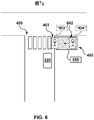
Figure 6 depicts the vehicle of the networked computing environment ofFigure 2 stopped at the crosswalk at another moment in time and where the object-inclusion zone is detected in proximity to the crosswalk and where some object is exiting the object-inclusion zone and begins crossing the crosswalk, in accordance with at least some embodiments of the present technology. -
Figure 7 is a schematic block representation of a method of operating the vehicle, in accordance with at least some embodiments of the present technology. - The examples and conditional language recited herein are principally intended to aid the reader in understanding the principles of the present technology and not to limit its scope to such specifically recited examples and conditions. It will be appreciated that those skilled in the art may devise various arrangements which, although not explicitly described or shown herein, nonetheless embody the principles of the present technology and are included within its spirit and scope.
- Furthermore, as an aid to understanding, the following description may describe relatively simplified implementations of the present technology. As persons skilled in the art would understand, various implementations of the present technology may be of a greater complexity.
- In some cases, what are believed to be helpful examples of modifications to the present technology may also be set forth. This is done merely as an aid to understanding, and, again, not to define the scope or set forth the bounds of the present technology. These modifications are not an exhaustive list, and a person skilled in the art may make other modifications while nonetheless remaining within the scope of the present technology. Further, where no examples of modifications have been set forth, it should not be interpreted that no modifications are possible and/or that what is described is the sole manner of implementing that element of the present technology.
- Moreover, all statements herein reciting principles, aspects, and implementations of the technology, as well as specific examples thereof, are intended to encompass both structural and functional equivalents thereof, whether they are currently known or developed in the future. Thus, for example, it will be appreciated by those skilled in the art that any block diagrams herein represent conceptual views of illustrative circuitry embodying the principles of the present technology.
- Similarly, it will be appreciated that any flowcharts, flow diagrams, state transition diagrams, pseudo-code, and the like represent various processes which may be substantially represented in computer-readable media and so executed by a computer or processor, whether or not such computer or processor is explicitly shown.
- The functions of the various elements shown in the figures, including any functional block labelled as a "processor", may be provided through the use of dedicated hardware as well as hardware capable of executing software in association with appropriate software. When provided by a processor, the functions may be provided by a single dedicated processor, by a single shared processor, or by a plurality of individual processors, some of which may be shared.
- Moreover, explicit use of the term "processor" or "controller" should not be construed to refer exclusively to hardware capable of executing software, and may implicitly include, without limitation, digital signal processor (DSP) hardware, network processor, application specific integrated circuit (ASIC), field programmable gate array (FPGA), read-only memory (ROM) for storing software, random access memory (RAM), and non-volatile storage. Other hardware, conventional and/or custom, may also be included.
- Software modules, or simply modules which are implied to be software, may be represented herein as any combination of flowchart elements or other elements indicating performance of process steps and/or textual description. Such modules may be executed by hardware that is expressly or implicitly shown.
- With these fundamentals in place, we will now consider some non-limiting examples to illustrate various implementations of aspects of the present technology.
- Referring initially to
Figure 1 , there is depicted acomputer system 100 suitable for use with some implementations of the present technology, thecomputer system 100 comprising various hardware components including one or more single or multi-core processors collectively represented byprocessor 110, a solid-state drive 120, amemory 130, which may be a random-access memory or any other type of memory. Communication between the various components of thecomputer system 100 may be enabled by one or more internal and/or external buses (not shown) (e.g. a PCI bus, universal serial bus, IEEE 1394 "Firewire" bus, SCSI bus, Serial-ATA bus, etc.), to which the various hardware components are electronically coupled. - In at least some embodiments of the present technology, the solid-
state drive 120 stores program instructions suitable for being loaded into thememory 130 and executed by theprocessor 110 for determining a presence of an object. For example, the program instructions may be part of a vehicle control application executable by theprocessor 110. - In at least some embodiments of the present technology, it is contemplated that the
computer system 100 may have additional and/or optional components, such as anetwork communication module 140 for communication, via a communication network (for example, acommunication network 240 depicted inFigure 2 ) with other electronic devices and/or servers, localization modules (not depicted), and the like. -
Figure 2 illustrates anetworked computer environment 200 suitable for use with some embodiments of the systems and/or methods of the present technology. Thenetworked computer environment 200 comprises anelectronic device 210 associated with avehicle 220, or associated with a user (not depicted) who can operate thevehicle 220, aserver 235 in communication with theelectronic device 210 via the communication network 240 (e.g. the Internet or the like, as will be described in greater detail herein below). Optionally, thenetworked computer environment 200 can also include a GPS satellite (not depicted) transmitting and/or receiving a GPS signal to/from theelectronic device 210. It will be understood that the present technology is not limited to GPS and may employ a positioning technology other than GPS. It should be noted that the GPS satellite can be omitted altogether. - The
vehicle 220, with which theelectronic device 210 is associated, may comprise any leisure or transportation vehicle such as a private or commercial car, truck, motorbike or the like. The vehicle may be user operated or a driver-less vehicle. It should be noted that specific parameters of thevehicle 220 are not limiting, these specific parameters including: vehicle manufacturer, vehicle model, vehicle year of manufacture, vehicle weight, vehicle dimensions, vehicle weight distribution, vehicle surface area, vehicle height, drive train type (e.g. 2x or 4x), tyre type, brake system, fuel system, mileage, vehicle identification number, and engine size. - The implementation of the
electronic device 210 is not particularly limited, but as an example, theelectronic device 210 may be implemented as a vehicle engine control unit, a vehicle CPU, a vehicle navigation device (e.g. TomTom™, Garmin™), a tablet, and a personal computer built into thevehicle 220 and the like. Thus, it should be noted that theelectronic device 210 may or may not be permanently associated with thevehicle 220. Additionally or alternatively, theelectronic device 210 can be implemented in a wireless communication device such as a mobile telephone (e.g. a smart-phone or a radio-phone). In certain embodiments, theelectronic device 210 has adisplay 270. - The
electronic device 210 may comprise some or all of the components of thecomputer system 100 depicted inFigure 1 . In certain embodiments, theelectronic device 210 is on-board computer device and comprises theprocessor 110, solid-state drive 120 and thememory 130. In other words, theelectronic device 210 comprises hardware and/or software and/or firmware, or a combination thereof, for determining a trajectory of thevehicle 220 at a given road segment considering obstacles therein, as will be described in greater detail below. - In the non-limiting embodiments of the present technology, the
electronic device 210 comprises or has access to asensor system 230. According to these embodiments, thesensor system 230 may comprise a plurality of sensors allowing for various implementations of the present technology. Examples of the plurality of sensors include but are not limited to: cameras, LIDAR sensors, and RADAR sensors, etc. Thesensor system 230 is operatively coupled to theprocessor 110 for transmitting the so-captured information to theprocessor 110 for processing thereof, as will be described in greater detail herein below. - The
sensor system 230 can be mounted on an interior, upper portion of a windshield of thevehicle 220, but other locations are within the scope of the present disclosure, including on a back window, side windows, front hood, rooftop, front grill, or front bumper of thevehicle 220. In some non-limiting embodiments of the present technology, thesensor system 230 can be mounted in a dedicated enclosure (not depicted) mounted on the top of thevehicle 220. - Further, the spatial placement of the
sensor system 230 can be designed taking into account the specific technical configuration thereof, configuration of the enclosure, weather conditions of the area where thevehicle 220 is to be used (such as frequent rain, snow, and other elements) or the like. - In the non-limiting embodiments of the present technology, the
sensor system 230 may comprise a sensor configured to capture an image of a surroundingarea 260. In this regard thesensor system 230 may be a camera or a plurality thereof (not separately depicted). - How the camera is implemented is not particularly limited. For example, in one specific non-limiting embodiments of the present technology, the camera can be implemented as a mono camera with resolution sufficient to detect objects at pre-determined distances of up to about 30 m (although cameras with other resolutions and ranges are within the scope of the present disclosure).
- In some embodiments of the present technology, the camera (or one or more cameras that make up the implementation of the sensor system 230) is configured to capture a pre-determine portion of the surrounding
area 260 around thevehicle 220. In some embodiments of the present technology, the camera is configured to capture an image (or a series of images) that represent approximately 90 degrees of the surroundingarea 260 around thevehicle 220 that are along a movement path of thevehicle 220. - In other embodiments of the present technology, the camera is configured to capture an image (or a series of images) that represent approximately 180 degrees of the surrounding
area 260 around thevehicle 220 that are along a movement path of thevehicle 220. In yet additional embodiments of the present technology, the camera is configured to capture an image (or a series of images) that represent approximately 360 degrees of the surroundingarea 260 around thevehicle 220 that are along a movement path of the vehicle 220 (in other words, the entirety of the surrounding area around the vehicle 220). - In a specific non-limiting example, the camera can be of the type available from FLIR Integrated Imaging Solutions Inc., 12051 Riverside Way, Richmond, BC, V6W 1K7, Canada. It should be expressly understood that the camera can be implemented in any other suitable equipment.
- In the non-limiting embodiments of the present technology, the
sensor system 230 may further comprise a LIDAR instrument (not separately depicted). Lidar stands for LIght Detection and Ranging. It is expected that a person skilled in the art will understand the functionality of the LIDAR instrument, but briefly speaking, a transmitter (not depicted) of the LIDAR sends out a laser pulse and the light particles (photons) are scattered back to a receiver (not depicted) of the LIDAR instrument. The photons that come back to the receiver are collected with a telescope and counted as a function of time. Using the speed of light (∼3X10⁸ m/s), theprocessor 110 can then calculate how far the photons have travelled (in the round trip). Photons can be scattered back off of many different entities surrounding thevehicle 220, such as other particles (aerosols or molecules) in the atmosphere, other card, stationary objects or potential obstructions in front of thevehicle 220. - In a specific non-limiting example, the LIDAR instrument comprised in the
sensor system 230 can be implemented as the LIDAR based sensor that may be of the type available from Velodyne LiDAR, Inc. of 5521 Hellyer Avenue, San Jose, CA 95138, United States of America. It should be expressly understood that the LIDAR instrument can be implemented in any other suitable equipment. - In some embodiments of the present technology, the LIDAR instrument comprised in the
sensor system 230 can be implemented as a plurality of LIDAR based sensors, such as three, for example, or any other suitable number. - In the non-limiting embodiments of the present technology, the
sensor system 230 may further comprise a RAdio Detection And Ranging (RADAR) instrument (not separately depicted). Briefly speaking, the RADAR instrument is a detection instrument using radio waves to determine a range, angle and/or velocity of objects. The RADAR instrument includes a transmitter producing electromagnetic waves, an antenna used for transmitting and receiving electromagnetic waves, a receiver, and a processor to determine properties of the detected objects. - In alternative embodiments of the present technology, there may be a separate antenna for receiving waves, and a separate antenna for transmitting waves. The processor used for determining properties of surrounding objects may be the
processor 110. - In some embodiments of then present technology, the RADAR instrument used in the
sensor system 230 may comprise long-range, medium-range and short-range RADAR sensors. As a non-limiting example, the long-range RADAR sensor may be used for adaptive cruise control, automatic emergency braking, and forward collision warning, while the medium and short-range RADAR sensors may be used for park assist, cross-traffic alert, junction assist, and blind side detection. - In a specific non-limiting example, the RADAR instrument comprised in the
sensor system 230 may be of the type available from Robert Bosch GmbH of Robert-Bosch-Platz 1, 70839 Gerlingen, Germany. It should be expressly understood that the RADAR instrument can be implemented in any other suitable equipment. - In some non-limiting embodiments of the present technology, the
sensor system 230 may be used, by theprocessor 110, for image calibration. For example, using an image captured by the camera and the LIDAR point cloud captured by the LIDAR instrument, theprocessor 110 is configured to identify a given region of the image to correspond to a given region of the LIDAR point cloud captured by the LIDAR instrument. In other embodiments of the present technology, thesensor system 230 are calibrated such that for the image captured by the camera, the LIDAR point cloud captured by the LIDAR instrument, and the RADAR data captured by the RADAR instrument, theprocessor 110 is configured to identify a given region of the image to correspond to a given region of the LIDAR point cloud and the RADAR data. - In the non-limiting embodiments of the present technology, the
vehicle 220 further comprises or has access to other sensors (not separately depicted). The other sensors include one or more of: an inertial measurement unit (IMU), a Global Navigation Satellite System (GNSS) instrument, ground speed RADARs, ultrasonic SONAR sensors, odometry sensors including accelerometers and gyroscopes, mechanical tilt sensors, magnetic compass, and other sensors allowing operation of thevehicle 220. - As a non-limiting example, the IMU may be fixed to the
vehicle 220 and comprise three gyroscopes and three accelerometers for providing data on the rotational motion and linear motion of thevehicle 220, which may be used to calculate motion and position of thevehicle 220. - In some embodiments of the present technology, the
communication network 240 is the Internet. In alternative non-limiting embodiments, thecommunication network 240 can be implemented as any suitable local area network (LAN), wide area network (WAN), a private communication network or the like. It should be expressly understood that implementations of thecommunication network 240 are for illustration purposes only. How a communication link (not separately numbered) between theelectronic device 210 and thecommunication network 240 is implemented will depend inter alia on how theelectronic device 210 is implemented. Merely as an example and not as a limitation, in those non-limiting embodiments of the present technology where theelectronic device 210 is implemented as a wireless communication device such as a smartphone or a navigation device, the communication link can be implemented as a wireless communication link. Examples of wireless communication links include, but are not limited to, a 3G communication network link, a 4G communication network link, and the like. Thecommunication network 240 may also use a wireless connection with aserver 235. - In some embodiments of the present technology, the
server 235 is implemented as a conventional computer server and may comprise some or all of the components of thecomputer system 100 ofFigure 1 . In one non-limiting example, theserver 235 is implemented as a Dell™ PowerEdge™ Server running the Microsoft™ Windows Server™ operating system, but can also be implemented in any other suitable hardware, software, and/or firmware, or a combination thereof. In the depicted non-limiting embodiments of the present technology, the server is a single server. In alternative non-limiting embodiments of the present technology (not shown), the functionality of theserver 235 may be distributed and may be implemented via multiple servers. - In some non-limiting embodiments of the present technology, the
processor 110 of theelectronic device 210 can be in communication with theserver 235 to receive one or more updates. The updates can be, but are not limited to, software updates, map updates, routes updates, weather updates, and the like. - In some embodiments of the present technology, the
processor 110 can also be configured to transmit to theserver 235 certain operational data, such as routes travelled, traffic data, performance data, and the like. Some or all data transmitted between thevehicle 220 and theserver 235 may be encrypted and/or anonymized. - In
Figure 2 , there is also depicted astorage 250 communicatively coupled to theserver 235. In some embodiments, however, thestorage 250 may be communicatively coupled to theelectronic device 210 and/or may be implemented within theelectronic device 210 and/or may be communicatively coupled to any other processor of thenetworked computer environment 200. - In at least some embodiments, it is contemplated that the
storage 250 may be used by theserver 235, theelectronic device 210 and/or any other processor of thenetworked computer environment 200 as a memory device for storing information. Thestorage 250 is configured to to store information extracted, determined and/or generated by theprocessor 110 of theserver 235 and/or theelectronic device 210. Generally speaking, thestorage 250 may receive data from theprocessor 110 which was generated by theprocessor 110 during processing for temporary and/or permanent storage thereof and may provide stored data to theprocessor 110 for use thereof. It is contemplated that thestorage 250 may be split into several distributed storages, for providing a fault-tolerant storage system for example, without departing from the scope of the present technology. - It should be noted that in at least some embodiments of the present technology, the
storage 250 may be implemented locally on theelectronic device 210 and/or the server 235 (such as on a local memory, for example). It is also contemplated however that thestorage 250 may be implemented remotely from theelectronic device 210 and/or the server 235 (such as on a remote memory, for example). - In some embodiments of the present technology, broadly speaking, the
electronic device 210 may be configured to control operation of thevehicle 220. More specifically, theelectronic device 210 may be configured to control operation of thevehicle 220 when in proximity with a pre-determined zone, such as a crosswalk. In one example, theelectronic device 210 may be configured to determine operation-control data for controlling operation of thevehicle 220 when thevehicle 220 is approaching a given crosswalk. In another example, theelectronic device 210 may also be configured to determine operation-control data for controlling operation of thevehicle 220 when thevehicle 220 is stopped at the given crosswalk. - Developers of the present technology have devised methods and systems for controlling operation of the
vehicle 220 during its approach to the given crosswalk in a different manner to when thevehicle 220 is stopped at the given crosswalk. - For example, in at least some implementations of the present technology, the
vehicle 220 may be triggered to operate in a, in a sense, "courteous" manner when approaching the given crosswalk - that is, the operation-control data may be used to operate thevehicle 220 such that it is more likely that thevehicle 220 gives priority of way to pedestrian(s) (or other objects) at the given crosswalk. In another example, thevehicle 220 may be triggered to operate in a less "courteous" manner when thevehicle 220 is already stopped at the given crosswalk if compared to when thevehicle 220 is approaching the given crosswalk - that is, the operation-control data may be used to operate thevehicle 220 such that it is less likely that thevehicle 220 gives priority of way to pedestrian(s) (or other objects) when thevehicle 220 is stopped at the given crosswalk if compared to the likeliness of thevehicle 220 giving priority of way to pedestrian(s) (or other objects) during its approach to the given crosswalk. How theelectronic device 210 may be configured to determine such operation-control data in both situations will become apparent from the description herein further below. - Developers of the present technology have also devised methods and systems for reducing an amount of computer resources required for performing a decision-making process on whether to give priority of way at the given crosswalk to a pedestrian (or other object). Developers of the present technology have realized that at least some prior art solutions require performing redundant operations for making a decision on whether to give priority of way at the given crosswalk to a pedestrian (or other object).
- To better illustrate this, reference will now be made to
Figure 3 depicting the vehicle 220 (i) approaching acrosswalk 300 at a moment T1, and (ii) approaching thecrosswalk 300 at a moment T2 that is after the moment T1. - It should be noted that at the moment T1, the
electronic device 210 associated with thevehicle 220 may be configured to determine presence of thecrosswalk 300 in the proximity of thevehicle 220. In one implementation, theelectronic device 210 may be configured to acquire road map data from theserver 235, for example, which is indicative of the presence of thecrosswalk 300 in the proximity of thevehicle 220. In another implementation, theelectronic device 210 may be configured to acquire sensor data from thesensor system 230 of thevehicle 220, for example, which is indicative of the presence of thecrosswalk 300 in the proximity of thevehicle 220. It is contemplated that theelectronic device 210 may determine presence of thecrosswalk 300 in proximity of thevehicle 220 by employing both the road map data and the sensor data, without departing from the scope of the present technology. - It should also be noted that at the moment T1 the
electronic device 210 may be configured to determine presence of anobject 302 in proximity of thecrosswalk 300. In one implementation, theelectronic device 210 may be configured to acquire sensor data from thesensor system 230 of thevehicle 220, for example, and which is indicative of the presence of theobject 302 in proximity of thecrosswalk 300. As a result, theelectronic device 210 may be configured to assign a unique ID to theobject 302 at the moment T1 for identifying theobject 302 at the moment T1 and thereafter. As illustrated inFigure 3 , let it be assumed that theelectronic device 210 assigns a unique ID "ID1" to theobject 302 at the moment T1. - The
electronic device 210 may then be configured to, in a sense, make a decision on whether to give priority of way to theobject 302 identifiable via ID1 and, therefore, determine either to (i) let theobject 302 cross thecrosswalk 300 before triggering thevehicle 220 to drive through thecrosswalk 300, or otherwise (ii) trigger thevehicle 220 to drive through thecrosswalk 300 before theobject 302 identifiable via ID1. For sake of illustration, let it be assumed that theelectronic device 210 made the decision at the moment T1 to trigger thevehicle 220 to let theobject 302 identifiable as ID1 cross thecrosswalk 300 first. - It should be noted that there are many situations in which the
electronic device 210 may not be able to identify theobject 302 via a same unique ID at the moment T2 as theelectronic device 210 does during moment T1. Just as an example, theobject 302 may have been partially hidden between moments T1 and T2 by an obstacle, and thus be considered as a new object by theelectronic device 210. Irrespective of the specific reason why theelectronic device 210 is not able to identify theobject 302 via the same unique ID at the moment T2 as during the moment T1, theelectronic device 210 may identify theobject 302 during the moment T2 via a different unique ID. As illustrated inFigure 3 , let it be assumed that theelectronic device 210 detects presence of theobject 302 at the moment T2 and identifies theobject 302 at the moment T2 by a new unique ID "ID2". - This identification of the
object 302 via different unique IDs at the moments T1 and T2 may result in a redundant decision-making process regarding the priority of way between thevehicle 220 and theobject 302 at thecrosswalk 300. It should be recalled that theelectronic device 210 may be storing data indicative of the priority of way of a given object identifiable via ID1 at thecrosswalk 300, but does not have data indicative of a priority of way of a given object identifiable via ID2 at thecrosswalk 300, since this data has not yet been computed. As such, theelectronic device 210 would need to perform the decision-making process anew for the given object identifiable via ID2, even though the decision to let theobject 302 cross thecrosswalk 300 first has been previously made during the moment T1. - Given the above scenario, the
electronic device 210 would need to perform the decision-making process on the priority of way for theobject 302 at the moment T1 and at the moment T2, which results in an unnecessary use of computer resources. As mentioned above, developers of the present technology have devised methods and systems that allow reducing the amount of redundant computations for making a decision on whether to give priority of way to an object or not to; and more specifically, to address the situation that has been presented immediately above. How theelectronic device 210 may be configured to perform such resource-efficient decision-making process will now be describe with reference toFigure 4 . - In
Figure 4 , similarly toFigure 3 , there is depicted the vehicle 220 (i) approaching acrosswalk 400 at the moment T1, and (ii) approaching thecrosswalk 400 at the moment T2 that is after the moment T1. - It should be noted that at the moment T1, the
electronic device 210 associated with thevehicle 220 may be configured to determine presence of thecrosswalk 400 in the proximity of thevehicle 220. In one implementation, theelectronic device 210 may be configured to acquire road map data from theserver 235, for example, which is indicative of the presence of thecrosswalk 400 in the proximity of thevehicle 220. In another implementation, theelectronic device 210 may be configured to acquire sensor data from thesensor system 230 of thevehicle 220, for example, which is indicative of the presence of thecrosswalk 400 in the proximity of thevehicle 220. - In some embodiments of the present technology, the
electronic device 210 may be configured to identify an object-inclusion zone 450 in proximity to thecrosswalk 400. Broadly speaking, the object-inclusion zone 450 is a given zone in proximity of thecrosswalk 400 that can potentially include objects that are to cross thecrosswalk 400. - The
electronic device 210 may be configured to identify the object-inclusion zone 450 in any suitable manner for a given application. In some non-limiting embodiments of the present technology, the size of the object-inclusion zone 450 is pre-determined. As an example, the object-inclusion zone 450 may be identified as a rectangular box sized 2m x 5m area of a side walk being located at one end of thecrosswalk 400. Nevertheless, object-inclusion zones having smaller areas or larger areas than the previously mentioned area are also contemplated in at least some embodiments of the present technology. In other non-limiting embodiments of the present technology, the size of the object-inclusion zone 450 may be proportionate to the size of thecrosswalk 400. As an example, the larger the size of thecrosswalk 400, the larger the size of the object-inclusion zone 450. In yet further non-limiting embodiments of the present technology, the shape of the object-inclusion zone 450 can be other than a rectangular box, such as a polygon-shaped zone, irregular shape zone, or the like. - It should be noted that in some embodiments, the
electronic device 210 may be configured to identify more than one object-inclusion zone in proximity to thecrosswalk 400. For example, theelectronic device 210 may be configured to identify an other object-inclusion zone (not depicted) on a left end of thecrosswalk 400, similarly to how theelectronic device 210 is configured to identify the object-inclusion zone 450 on a right end of thecrosswalk 400. - The
electronic device 210 may be configured to determine presence of anobject 402 in the object-inclusion zone 450. In one implementation, theelectronic device 210 may be configured to acquire sensor data from thesensor system 230 of thevehicle 220, for example, which is indicative of the presence of theobject 402 in the object-inclusion zone 450. As a result, theelectronic device 210 may be configured to assign a unique ID to theobject 402 at the moment T1 for identifying theobject 402 at the moment T1. As illustrated inFigure 4 , let it be assumed that theelectronic device 210 assigns a unique ID "ID1" to theobject 402 at the moment T1. - In some embodiments of the present technology, the
electronic device 210 may be configured to acquire movement data for theobject 402. In one implementation, theelectronic device 210 may receive sensor data from thesensor system 230 of the vehicle, for example, which is indicative of movement data of theobject 402. For example, movement data of theobject 402 may be indicative of current position, current velocity, and/or current acceleration of theobject 402 and/or predicated future position, predicted future velocity, and/or predicted future acceleration ofobject 402. Put another way, the movement data of theobject 402 may be indicative of a current movement of theobject 402 and/or predicted future movement of theobject 402. - In some embodiments, the
electronic device 210 may also be configured to acquire movement data of thevehicle 220. Theelectronic device 210 may be configured to acquire the movement data of thevehicle 220 in any suitable manner for a given application. - Irrespective of how the
electronic device 210 acquires the movement data for theobject 402 and thevehicle 220, with reference toFigure 5 , there is depicted afirst representation 500 of how theelectronic device 210 may be configured to use the movement data of theobject 402 and of thevehicle 220. - The
electronic device 210 may be configured to determine an interval oftime 504 for theobject 402 based on the movement data of theobject 402. Broadly speaking, the interval oftime 504 forobject 402 is indicative of a temporal window during which theobject 402 is estimated/predicted to be crossing thecrosswalk 400. For example, theelectronic device 210 may be configured employ the movement data of theobject 402 in order to determine (i) a moment in time t30 when theobject 402 is estimated to engage thecrosswalk 400 and thereby start crossing thecrosswalk 400, and (ii) a moment in time t40 when theobject 402 is estimated to disengage thecrosswalk 400 and thereby finish crossing thecrosswalk 400 at the other side thereof. - In some embodiments, the
electronic device 210 may also be configured to determine an other interval oftime 502 for thevehicle 220 based on movement data of thevehicle 220. Broadly speaking, the interval oftime 502 forvehicle 220 is indicative of a temporal window during which thevehicle 220 is estimated/predicted to be driving through thecrosswalk 400. For example, theelectronic device 210 may be configured employ the movement data of thevehicle 220 in order to determine (i) a moment in time t10 when thevehicle 220 is estimated to engage thecrosswalk 400 and thereby start driving through thecrosswalk 400, and (ii) a moment in time t20 when thevehicle 220 is estimated to disengage thecrosswalk 400 and thereby finish driving through thecrosswalk 400. - In some embodiments of the present technology, the
electronic device 210 may be configured to determine the interval oftime 504 and the interval oftime 502 in a common time referential as illustrated inFigure 5 . As seen, the interval oftime 502 is not overlapping the interval oftime 504, which means that theelectronic device 210 determined, based on the movement data of theobject 402 and of thevehicle 220, that thevehicle 220 is estimated to drive through thecrosswalk 400 before theobject 402 engages thecrosswalk 400 and starts crossing it. In particular, theelectronic device 210 may be configured to determine asafety interval 520 bounded (i) by the moment in time t20 corresponding to when thevehicle 220 is estimated to disengage thecrosswalk 400 and thereby finish driving through thecrosswalk 400, and by (ii) the moment in time t30 corresponding to when theobject 402 is estimated to engage thecrosswalk 400 and thereby start crossing thecrosswalk 400. - However, in at least some embodiments of the present technology, with reference to
representation 550 ofFigure 5 , theelectronic device 210 may be configured to determine a buffered interval oftime 510 for theobject 402. Broadly speaking, theelectronic device 210 may be configured to determine the buffered interval oftime 510 by adding atime buffer 506 to the interval oftime 502 so as to enlarge the temporal window during which theobject 402 is estimated to be crossing thecrosswalk 400. As such, theelectronic device 210 may be configured to determine the buffered interval oftime 510 by determining (i) a moment in time t300 and (ii) a moment in time t400, by adding a respective portion of thetime buffer 506 on each end of the interval oftime 504. - It is contemplated that the
electronic device 210 may be configured to add thetime buffer 506 to the interval oftime 504 for different reasons. In one case, theelectronic device 210 may be configured to determine the buffered interval oftime 510 for safety purposes if ever the temporal window for theobject 402 is erroneously estimated based on the movement data of theobject 402. In an other case, theelectronic device 210 may be configured to determine the buffered interval oftime 510 for courteous purposes to increase a number of instances when theelectronic device 210 is to trigger thevehicle 220 to let theobject 402 cross thecrosswalk 400 before driving through it. - The length of time represented by the
time buffer 506 may be determined in any suitable manner for a given application. However, as it will become apparent from the description herein below, it is contemplated that the length of time representing a given time buffer being added to a given interval of time for a given object may be different depending on whether thevehicle 220 is approaching thecrosswalk 400 or whether thevehicle 220 is stopped at thecrosswalk 400. - As seen in
Figure 5 , the buffered interval oftime 510 of theobject 402 is partially overlapping the interval oftime 502 of thevehicle 220. In other words, theelectronic device 210 may determine an overlappinginterval 530 indicative of that thevehicle 220 is estimated to still be driving through thecrosswalk 400 when theobject 402 is estimated to engage thecrosswalk 400 and, thus, that a modification to the trajectory of thevehicle 220 may be required, such as stopping, for example. - Overall, it can be said the
electronic device 210 is configured to (i) determine the interval oftime 504 for theobject 402 based on the movement data of the object 402 (and, optionally determine the buffered interval oftime 510 for theobject 402 based on the interval oftime 504 and the time buffer 506), (ii) use the interval of time 502 (and, optionally the buffered interval of time 510) and the movement data of thevehicle 220 to determine operation-control data for controlling operation of thevehicle 220, and where the operation-control data is indicative of a decision on a priority of way through thecrosswalk 400 between thevehicle 220 and theobject 402. - For example, if the
electronic device 210 determines that the interval of time 504 (or potentially, the buffered interval of time 510) at least partially overlaps the interval oftime 502 of thevehicle 220, the operation-control data may be indicative of a decision that theobject 402 has priority of way through thecrosswalk 400 before thevehicle 220. In this case, the operation-control data may be used by theelectronic device 210 to trigger thevehicle 220 to stop at thecrosswalk 400, before driving through it, and let theobject 402 cross thecrosswalk 400 first. - In another example, if the
electronic device 210 determines that the interval of time 504 (or potentially, the buffered interval of time 510) does not overlap the interval oftime 502 of thevehicle 220, the operation-control data may be indicative of a decision that thevehicle 220 has priority of way through thecrosswalk 400 before theobject 402. In this case, the operation-control data may be used by theelectronic device 210 to trigger thevehicle 220 to drive through thecrosswalk 400, before theobject 402 engages thecrosswalk 400 and starts crossing it. - Returning to
Figure 4 , irrespective of what decision is taken on the priority of way between thevehicle 220 and theobject 402, in some embodiments of the present technology, theelectronic device 210 may be configured to assigndecision data 455 that is indicative of this decision to the object-inclusion zone at the moment T1 so that it can be employed at a later moment, such as the moment T2, for example. - It should be noted that the
decision data 455, although determined at least partially based on the movement data of theobject 402 identifiable via ID1 at the moment T1, is assigned to the object-inclusion zone 450, as opposed to being assigned to theobject 402 identifiable via ID1 at the moment T1. As it will now be discussed in greater details herein below, developers of the present technology have realized that assigning thedecision data 455 to the object-inclusion zone 450, instead of assigning thedecision data 455 to a given object identifiable via some unique ID, allows avoiding redundant computation of decision data at later moments in time, such as at the moment T2, for example. - Indeed, by assigning the
decision data 455 to the object-inclusion zone 450 allows theelectronic device 210 to, in a sense, access "knowledge" regarding the priority of way between thevehicle 220 and any object in the object-inclusion zone 450 that is identifiable by a different unique ID than the unique ID of an object based on which thedecision data 455 has been determined. - To better illustrate this, let it be assumed that at the moment T2, irrespective of the reason therefor, the
object 402 is now identified by a unique ID "ID2" which is different from the unique ID "ID1" of theobject 402 at the moment T1. Hence, for all intents and purposes, theelectronic device 210 appreciates theobject 402 with the unique ID "ID2" at the moment T2 as a different object from theobject 402 with the unique ID "ID1" at the moment T1. However, instead of unnecessarily repeating the decision-making process on the priority of way between thevehicle 220 and theobject 402 identifiable via "ID2" at the moment T2, theelectronic device 210 may be configured to access thedecision data 455 associated with the object-inclusion zone 450 and determine that thevehicle 220 has priority of way over theobject 402 identifiable via "ID2" at the moment T2. - As a result, by accessing the
decision data 455 at the moment T2, theelectronic device 210 does not require to repeat the decision-making process on the priority of way and does not require re-computation of operation-control data for thevehicle 220 at the moment T2 and, instead, use the operation-control data that has been determined for thevehicle 220 at the moment T1. This means that at the moment T2, although theelectronic device 210 detects presence of theobject 402 identifiable by a given unique ID for which it has not yet made a decision on priority of way, theelectronic device 210 may access thedecision data 455 assigned to the object-inclusion zone 450 in which theobject 402 identifiable by this given unique ID is located and, as a result, employs the operation-control data that has been determined at the moment T1 in order to control operation of thevehicle 220 at the moment T2. Hence, theelectronic device 210 may be configured to trigger thevehicle 220 to stop at thecrosswalk 400 and let theobject 402 identifiable via the unique ID "ID2" to cross thecrosswalk 400 first. - With reference to
Figure 6 , there is depicted thevehicle 220 stopped at thecrosswalk 400 at a moment T3, that is after the moment T2. For example, theelectronic device 210 may be configured to trigger thevehicle 220 to operate in accordance with the operation-control data and, in this case as mentioned above, theelectronic device 210 may be configured to trigger thevehicle 220 to stop at thecrosswalk 400 and allow any object from the object-inclusion zone 450 to cross thecrosswalk 400 first. - In at least some embodiments of the present technology, in response to any object from the object-
inclusion zone 450 exiting the object-inclusion zone 450 and beginning crossing thecrosswalk 400, theelectronic device 210 may be configured to assignnew decision data 655 to the object-inclusion zone 450. Put another way, in response to any object from the object-inclusion zone 450 exiting the object-inclusion zone 450 and beginning crossing thecrosswalk 400, theelectronic device 210 may be configured to perform anew the decision-making process for the object-inclusion zone 450. - For example, as illustrated, let it be assumed that the
object 402 at the moment T3 is identifiable via a unique ID "ID3". As mentioned above, there are different reasons why theobject 402 may be identifiable by a different unique ID at the moment T3 than at the moments T1 and T2. However, regardless of theobject 402 being identifiable via the unique ID "ID3" at the moment T3, theelectronic device 210 may be configured to use the sensor data of thevehicle 220 to determine that some object (in this case, theobject 402 being identifiable via the unique ID "ID3") from the object-inclusion zone 450 is exiting the object-inclusion zone 450 and begins to cross thecrosswalk 400 at the moment T3. - Also, the moment T3, the
electronic device 210 may be configured to use the sensor data of thevehicle 220 to determine presence of asecond object 602 in the object-inclusion zone 450. For example, theelectronic device 210 may be configured to identify thesecond object 602 at the moment T3 via a unique ID "ID4". It should be noted that, since theelectronic device 210 determines that some object is exiting the object-inclusion zone 450 and begins crossing thecrosswalk 400 at the moment T3, theelectronic device 210 may be configured to determine thenew decision data 655 for the object-inclusion zone 450 at the moment T3 based on thesecond object 602 identifiable via unique ID "ID4" at the moment T3. - Similarly to how the
electronic device 210 is configured to determine the interval of time 504 (or potentially the buffered interval of time 510) for theobject 402 at the moment T1, theelectronic device 210 may be configured to determine a second interval of time for thesecond object 602 at the moment T3 based on movement data of thesecond object 602. Theelectronic device 210 is thereby configured to determine a second temporal window for thesecond object 602 during which thesecond object 602 is estimated to be crossing thecrosswalk 400. - Then, the
electronic device 210 may be configured to use movement data of thevehicle 220 and the second interval of time of thesecond object 602 for determining new operation-control data for controlling operation of thevehicle 220. The new operation-control data is indicative of a new decision on a priority of way through thecrosswalk 400 between thevehicle 220 and thesecond object 602. - As a result, at the moment T3, the
electronic device 210 may be configured to assign thenew decision data 655 to the object-inclusion zone 450 that is indicative of the new decision on the priority of way. Let it be assumed that the second interval of time for thesecond object 602 does not overlap an interval of time of thevehicle 220 during which thevehicle 220 may cross thecrosswalk 400. As such, the new operation-control data may be indicative of a decision to let thevehicle 220 drives through thecrosswalk 400 before thesecond object 602 crosses thecrosswalk 400. - As previously alluded to, developers of the present technology have devised methods and systems for controlling operation of the
vehicle 220 during its approach to thecrosswalk 400 in a different manner to when thevehicle 220 is stopped at thecrosswalk 400. - For example, the
vehicle 220 may be triggered to operate in a less "courteous" manner when thevehicle 220 is already stopped at thecrosswalk 400 if compared to when thevehicle 220 is approaching thecrosswalk 400. In at least some embodiments of the present technology, developers of the present technology have realized that this may be achieved by employing different time buffers for determining buffered intervals of time depending on whether thevehicle 220 is approaching thecrosswalk 400 or whether thevehicle 220 is already stopped at thecrosswalk 400. - As mentioned above, during the moment T1, the
electronic device 210 may be configured to determine the buffered interval oftime 510 based on the interval oftime 504 for theobject 402 and on the time buffer 506 (seeFigure 5 ). It should be noted that, the larger the length of time representing thetime buffer 506, the more likely there will be an overlap between the interval oftime 502 of thevehicle 220 and the buffered interval oftime 510, and hence, the more likely that the decision-making process results in theobject 402 having priority of way over thevehicle 220. - Hence, the
electronic device 210 may be configured to use a somewhat larger time buffer for determining the buffered interval of time for a given object when thevehicle 220 is approaching thecrosswalk 400 so as to operate thevehicle 220 in a more "courteous" manner during the approach. However, theelectronic device 210 may be configured to use a somewhat smaller time buffer for determining the buffered interval of time for a given object when thevehicle 220 is stopped at thecrosswalk 400 so as to operate thevehicle 220 in a less "courteous" manner during a moment when thevehicle 220 is stopped. Put another way, theelectronic device 210 may be configured to trigger thevehicle 220 to operate in a less "courteous" manner when thevehicle 220 is already stopped at thecrosswalk 400 if compared to when thevehicle 220 is approaching thecrosswalk 400, by employing a given time buffer during a moment when thevehicle 220 is stopped that has a shorter length in time than the length of time of thetime buffer 506 that is employed at a moment when thevehicle 220 is approaching thecrosswalk 400. - In some embodiments of the present technology, the
electronic device 210 may be configured to execute amethod 700, depicted via a block diagram representation inFigure 7 , of controlling operation of a SDC. For example, the SDC may be implemented as thevehicle 220 communicatively coupled to theelectronic device 210. It should be noted that some steps of themethod 700 may be executed by theelectronic device 210 at a first moment in time during an approach of the SDC to a given crosswalk, while other steps of themethod 700 may be executed by theelectronic device 210 at a second moment in time while the SDC is stopped at the given crosswalk. In some cases, the second moment in time may be after the first moment in time. Various steps of themethod 700 will now be discussed in greater detail herein below. - The
method 700 begins atstep 702 with theelectronic device 210 configured to, at a first moment in time during an approach of thevehicle 220 to the crosswalk 400 (seeFigure 4 ), identify the object-inclusion zone 450 in proximity to thecrosswalk 400. For example, theelectronic device 210 may be configured to identify the object-inclusion zone 450 at the moment T1. - It is contemplated that the
electronic device 210 may be configured to identify the object-inclusion zone 450 in any suitable manner for a given application. As previously alluded to, the size of the object-inclusion zone 450 may be pre-determined. As an example, the object-inclusion zone 450 may be identified as a rectangular box sized 2m x 5m area of a side walk being located at one end of thecrosswalk 400. Nevertheless, object-inclusion zones having smaller areas or larger areas than the previously mentioned area are also contemplated in at least some embodiments of the present technology. - In other non-limiting embodiments of the present technology, the size of the object-
inclusion zone 450 may be proportionate to the size of thecrosswalk 400. As an example, the larger the size of thecrosswalk 400, the larger the size of the object-inclusion zone 450. In yet further non-limiting embodiments of the present technology, the shape of the object-inclusion zone 450 can be other than a rectangular box, such as a polygon-shaped zone, irregular shape zone, or the like. - Optionally, the
electronic device 210 may be configured to identify more than one object-inclusion zone in proximity to thecrosswalk 400, such as one in proximity to each end of thecrosswalk 400. - The
method 700 continues to step 704 with theelectronic device 210 configured to, at the first moment in time during an approach of thevehicle 220 to the crosswalk 400 (e.g., at the moment T1), determine presence of theobject 402 in the object-inclusion zone 450. - For example, the
electronic device 210 may be configured to acquire sensor data from thesensor system 230 of thevehicle 220 which is indicative of the presence of theobject 402 in the object-inclusion zone 450. As a result, theelectronic device 210 may be configured to assign a unique ID to theobject 402 at the moment T1 for identifying theobject 402 at the moment T1. As illustrated inFigure 4 , theelectronic device 210 may be configured to assign a unique ID "ID1" to theobject 402 at the moment T1. - It is also contemplated that the
electronic device 210 may be configured to acquire the movement data of theobject 402. In one implementation, theelectronic device 210 may receive sensor data from thesensor system 230 of the vehicle, for example, which is indicative of movement data of theobject 402. For example, movement data of theobject 402 may be indicative of current position, current velocity, and/or current acceleration of theobject 402 and/or predicated future position, predicted future velocity, and/or predicted future acceleration ofobject 402. Put another way, the movement data of theobject 402 may be indicative of a current movement of theobject 402 and/or predicted future movement of theobject 402. - The
method 700 continues to step 706 with theelectronic device 210 configured to, at the first moment in time during an approach of thevehicle 220 to the crosswalk 400 (e.g., at the moment T1), determine the interval of time 504 (seeFigure 5 ) for theobject 402 based on the movement data of theobject 402. - Broadly speaking, the interval of
time 504 forobject 402 is indicative of a temporal window during which theobject 402 is estimated/predicted to be crossing thecrosswalk 400. For example, theelectronic device 210 may be configured employ the movement data of theobject 402 in order to determine (i) the moment in time t30 when theobject 402 is estimated to engage thecrosswalk 400 and thereby start crossing thecrosswalk 400, and (ii) the moment in time t40 when theobject 402 is estimated to disengage thecrosswalk 400 and thereby finish crossing thecrosswalk 400 at the other side thereof. - In some embodiments, the
electronic device 210 may further be configured to determine the buffered interval oftime 510 based on the interval oftime 504 and thetime buffer 506 so as to enlarge the temporal window during which theobject 402 is estimated to be crossing thecrosswalk 400. This buffered interval oftime 510 may be used during a further step of the method 700 (e.g., step 708) instead of the interval oftime 504 for determining operation-control data for thevehicle 220. This may be performed for at least one of safety and/or courteous purposes, as discussed above. - The
method 700 continues to thestep 708 with theelectronic device 210 configured to, at the first moment in time during an approach of thevehicle 220 to the crosswalk 400 (e.g., at the moment T1), use the interval of time 504 (and/or optionally the buffered interval of time 510) and the movement data of thevehicle 220 for determining the operation-control data for controlling operation of thevehicle 220. - As mentioned above, the operation-control data is indicative of a decision on a priority of way through the
crosswalk 400 between thevehicle 220 and theobject 402. - In some embodiments, during the
step 708, theelectronic device 210 may be configured to determine the other interval oftime 502 for thevehicle 220 based on the movement data of thevehicle 220. Broadly speaking, the interval oftime 502 forvehicle 220 is indicative of a temporal window during which thevehicle 220 is estimated/predicted to be driving through thecrosswalk 400. For example, theelectronic device 210 may be configured employ the movement data of thevehicle 220 in order to determine (i) the moment in time t10 when thevehicle 220 is estimated to engage thecrosswalk 400 and thereby start driving through thecrosswalk 400, and (ii) the moment in time t20 when thevehicle 220 is estimated to disengage thecrosswalk 400 and thereby finish driving through thecrosswalk 400. - It can be said that in at least some embodiments of the present technology, the
electronic device 210 may be configured to determine the operation-control data based on weather or not the interval oftime 502 of the object 402 (and/or optionally the buffered interval of time 504) at least partially overlaps the other interval of time of thevehicle 220. - For example, if the interval of
time 502 of the object 402 (and/or optionally the buffered interval of time 504) at least partially overlaps the other interval of time of thevehicle 220, then the operator-control data may be indicative of a decision that theobject 402 has the priority of way through thecrosswalk 400. - In another example, if the interval of
time 502 of the object 402 (and/or optionally the buffered interval of time 504) does not overlap the other interval of time of thevehicle 220, then the operator-control data may be indicative of a decision that thevehicle 220 has the priority of way through thecrosswalk 400. - In at least some embodiments of the present technology, the
electronic device 210 may further be configured to trigger thevehicle 220 to operate in accordance with the operation-control data. - In the example where the operator-control data is indicative of a decision that the
object 402 has the priority of way through thecrosswalk 400, theelectronic device 210 may be configured to trigger thevehicle 220 to stop at thecrosswalk 400 and allow any object from the object-inclusion zone 450 to cross thecrosswalk 400. - In the example where the operator-control data is indicative of a decision that the
vehicle 220 has the priority of way through thecrosswalk 400, theelectronic device 210 may be configured to trigger thevehicle 220 to pass through thecrosswalk 400 before any object from the object-inclusion zone 450 crosses thecrosswalk 400. - The
method 700 continues to step 710 with theelectronic device 210 configured to, at the first moment in time during an approach of thevehicle 220 to the crosswalk 400 (e.g., at the moment T1), assign thedecision data 455 to the object-inclusion zone 450 which is indicative of the decision regarding the priority of way through thecrosswalk 400 between thevehicle 220 and theobject 402. - It should be noted that the
electronic device 210 may be configured to assign thedecision data 455 to the object-inclusion zone 450 by storing information that associates with the object-inclusion zone 450 with thedecision data 455 in a suitable storage. It should also be noted that this assignment of thedecision data 455 to the object-inclusion zone 450 (as opposed to assignment of thedecision data 455 to theobject 402 identifiable via the first unique ID "ID1", for example) is performed such that the priority of way between (i) thevehicle 220 and (ii) any other object identifiable by an other unique ID that is different from the first unique ID "ID1" in the object-inclusion zone 450, is the same as between thevehicle 220 and theobject 402 identifiable via the first unique ID "ID1". - For example, as seen in
Figure 4 , at the moment T2 which is after the moment T1 during the approach of thevehicle 220 to thecrosswalk 400, theobject 402 is no longer identifiable via the first unique ID "ID1", but rather by a second unique ID "ID2". Nevertheless, since thedecision data 455 is assigned to the object-inclusion zone 450 (instead of being assigned to theobject 402 indefinable via "ID1") theelectronic device 210 may determine that the decision on the priority of way between theobject 402 indefinable via "ID2" and thevehicle 220 is already computed and hence can be used without redundant computation. - In at least some embodiments of the present technology, at least some additional steps may be performed by the electronic device when the
vehicle 220 is stopped at thecrosswalk 400. Let it be assumed that, at the the first moment in time during the approach of the SDC to the crosswalk 400 (e.g., the moment T1), theelectronic device 210 triggers (based on the operation-control data) thevehicle 220 to stop at thecrosswalk 400 and allows any object from the object-inclusion zone 450 to cross thecrosswalk 400. In such a case, at the second moment in time while thevehicle 220 is stopped at the crosswalk 400 (e.g., the moment T3 onFigure 6 ), theelectronic device 210 may be configured to, in response to any object from the object-inclusion zone 450 exiting the object-inclusion zone 450 and beginning crossing thecrosswalk 400, assign thenew decision data 655 to the object-inclusion zone 450 indicative of a new decision. In at least some embodiments of the present technology, theelectronic device 210 may be configured to determine thenew decision data 655 in accordance with the presence of thesecond object 602 identifiable via "ID4" similarly to how theelectronic device 210 determined thedecision data 455 in accordance with the presence of theobject 402 identifiable via "ID1". - However, it should be noted that in cases where the
electronic device 210 is configured to use the buffered interval oftime 510 for further determining thedecision data 455, theelectronic device 210 may also use an other buffered interval of time at the second moment in time (e.g., the moment T3). However, theelectronic device 210 may be configured use a smaller time buffer for determining the other buffered interval of time than thetime buffer 506 used to determine the buffered interval oftime 510. - It should be expressly understood that not all technical effects mentioned herein need to be enjoyed in each and every embodiment of the present technology.
- Modifications and improvements to the above-described implementations of the present technology may become apparent to those skilled in the art. The foregoing description is intended to be exemplary rather than limiting. The scope of the present technology is therefore intended to be limited solely by the scope of the appended claims.
Claims (14)
- A computer-implemented method (700) for controlling operation of a Self-Driving Car (SDC) (220), the method (700) executable by an electronic device (210) coupled to the SDC (220), the method (700) comprising:
at a first moment in time during an approach of the SDC (220) to a crosswalk (400):• identifying, by the electronic device (210), an object-inclusion zone (450) in proximity to the crosswalk (400), the object-inclusion zone (450) potentially including objects (402) that are to cross the crosswalk (400);• determining, by the electronic device (210), presence of an object (402) in the object-inclusion zone (450), the object (402) being identifiable by a first unique ID;• determining, by the electronic device (210), an interval of time (502) for the object (402) based on movement data of the object (402), the interval of time (502) being indicative of a temporal window during which the object (402) is estimated to be crossing the crosswalk (400);• using, by the electronic device (210), the interval of time (502) and movement data of the SDC (220) for determining operation-control data for controlling operation of the SDC (220), the operation-control data being indicative of a decision on a priority of way through the crosswalk (400) between the SDC (220) and the object (402); and• assigning, by the electronic device (210), decision data to the object-inclusion zone (450) indicative of the decision, such that the priority of way between the SDC (220) and any other object identifiable by an other unique ID that is different from the first unique ID in the object-inclusion zone (450) is same as between the SDC (220) and the object (402). - The method (700) of claim 1, wherein the method (700) further comprises, at the first moment in time during the approach of the SDC (220) to the crosswalk (400): triggering, by the electronic device (210), the SDC (220) to operate in accordance with the operation-control data.
- The method (700) of claim 2, wherein the triggering comprises one of:• triggering, by the electronic device (210), the SDC (220) to stop at the crosswalk (400) and allowing any object (402) from the object-inclusion zone (450) to cross the crosswalk (400); and• triggering, by the electronic device (210), the SDC (220) to pass through the crosswalk (400) before any object (402) from the object-inclusion zone (450) crosses the crosswalk (400).
- The method (700) of claim 1, wherein the method (700) further comprises:at the first moment in time during the approach of the SDC (220) to the crosswalk (400), triggering, by the electronic device (210) based on the operation-control data, the SDC (220) to stop at the crosswalk (400) and allowing any object from the object-inclusion zone (450) to cross the crosswalk (400); andat a second moment in time while the SDC (220) is stopped at the crosswalk (400): in response to any object (402) from the object-inclusion zone (450) exiting the object-inclusion zone (450) and beginning crossing the crosswalk (400), assigning, by the electronic device (210), new decision data to the object-inclusion zone (450) indicative of a new decision.
- The method (700) of claim 4, wherein in response to the any object from the object-inclusion zone (450) exiting the object-inclusion zone (450) and beginning crossing the crosswalk (400), the method (700) further comprises:• determining, by the electronic device (210), presence of a second object in the object-inclusion zone (450), the second object being identifiable by a second unique ID;• determining, by the electronic device (210), a second interval of time for the second object based on movement data of the second object, the second interval of time being indicative of a second temporal window during which the second object is estimated to be crossing the crosswalk (400);• using, by the electronic device (210), the second interval of time and movement data of the SDC (220) for determining new operation-control data for controlling operation of the SDC (220), the new operation-control data being indicative of a new decision on a priority of way through the crosswalk (400) between the SDC (220) and the second object;and wherein the assigning the new decision data to the object-inclusion zone (450) indicative of the new decision is performed by the electronic device (210), such that the priority of way between the SDC (220) and any other object identifiable by an other unique ID that is different from the second unique ID in the object-inclusion zone (450) is same as between the SDC (220) and the second object.
- The method (700) of claim 5, wherein the method (700) further comprises:• determining, by the electronic device (210), a buffered interval of time (510) based on the interval of time (502) and a first time buffer, so as to enlarge the temporal window during which the object (402) is estimated to be crossing the crosswalk (400);• using, by the electronic device (210), the buffered interval of time (510) instead of the interval of time (502) for determining the operation-control data;• determining, by the electronic device (210), a second buffered interval of time based on the second interval of time and a second time buffer, so as to enlarge the second temporal window during which the second object is estimated to be crossing the crosswalk (400), the second time buffer being smaller than the first time buffer; and• using, by the electronic device (210), the second buffered interval of time instead of the second interval of time for determining the new operation-control data.
- The method (700) of any of claims 1-6, wherein the method (700) further comprises:• determining, by the electronic device (210), a buffered interval of time (510) based on the interval of time (502) and a first time buffer, so as to enlarge the temporal window during which the object (402) is estimated to be crossing the crosswalk (400); and• using, by the electronic device (210), the buffered interval of time (510) instead of the interval of time (502) for determining the operation-control data.
- An electronic device (210) for controlling operation of a Self-Driving Car (SDC) (220), the electronic device (210) coupled to the SDC (220), the electronic device (210) being configured to:
at a first moment in time during an approach of the SDC (220) to a crosswalk (400):• identify an object-inclusion zone (450) in proximity to the crosswalk (400), the object-inclusion zone (450) potentially including objects that are to cross the crosswalk (400);• determine presence of an object (402) in the object-inclusion zone (450), the object (402) being identifiable by a first unique ID;• determine an interval of time (502) for the object (402) based on movement data of the object (402), the interval of time (502) being indicative of a temporal window during which the object (402) is estimated to be crossing the crosswalk (400);• use the interval of time and movement data of the SDC (220) for determining operation-control data for controlling operation of the SDC (220), the operation-control data being indicative of a decision on a priority of way through the crosswalk (400) between the SDC (220) and the object (402); and• assign decision data to the object-inclusion zone (450) indicative of the decision,
such that the priority of way between the SDC (220) and any other object (402) identifiable by an other unique ID that is different from the first unique ID in the object-inclusion zone (450) is same as between the SDC (220) and the object (402). - The electronic device (210) of claim 8, wherein the electronic device (210) is further configured to, at the first moment in time during the approach of the SDC (220) to the crosswalk (400): trigger the SDC (220) to operate in accordance with the operation-control data.
- The electronic device (210) of claim 9, wherein to trigger the electronic device (210) is configured to one of:• trigger the SDC (220) to stop at the crosswalk (400) and allowing any object (402) from the object-inclusion zone (450) to cross the crosswalk (400); and• trigger the SDC (220) to pass through the crosswalk (400) before any object (402) from the object-inclusion zone (450) crosses the crosswalk (400).
- The electronic device (210) of claim 8, wherein the electronic device (210) is further configured to:at the first moment in time during the approach of the SDC (220) to the crosswalk (400), trigger based on the operation-control data, the SDC (220) to stop at the crosswalk (400) and allowing any object (402) from the object-inclusion zone (450) to cross the crosswalk (400);at a second moment in time while the SDC (220) is stopped at the crosswalk (400): in response to any object (402) from the object-inclusion zone (450) exiting the object-inclusion zone (450) and beginning crossing the crosswalk (400),assign new decision data to the object-inclusion zone (450) indicative of a new decision.
- The electronic device (210) of claim 11, wherein in response to the any object (402) from the object-inclusion zone (450) exiting the object-inclusion zone (450) and beginning crossing the crosswalk (400), the electronic device (210) is further configured to:• determine presence of a second object in the object-inclusion zone (450), the second object being identifiable by a second unique ID;• determine a second interval of time for the second object based on movement data of the second object, the second interval of time being indicative of a second temporal window during which the second object is estimated to be crossing the crosswalk (400);• use the second interval of time and movement data of the SDC (220) for determining new operation-control data for controlling operation of the SDC (220), the new operation-control data being indicative of a new decision on a priority of way through the crosswalk (400) between the SDC (220) and the second object; and
wherein the electronic device (210) is configured to assign the new decision data to the object-inclusion zone (450) indicative of the new decision such that the priority of way between the SDC (220) and any other object identifiable by an other unique ID that is different from the second unique ID in the object-inclusion zone (450) is same as between the SDC (220) and the second object. - The electronic device (210) of claim 12, wherein the electronic device (210) is further configured to:• determine a buffered interval of time (510) based on the interval of time (502) and a first time buffer, so as to enlarge the temporal window during which the object (402) is estimated to be crossing the crosswalk (400);• use the buffered interval of time (510) instead of the interval of time (502) for determining the operation-control data;• determine a second buffered interval of time based on the second interval of time and a second time buffer, so as to enlarge the second temporal window during which the second object is estimated to be crossing the crosswalk (400), the second time buffer being smaller than the first time buffer; and• use the second buffered interval of time (510) instead of the second interval of time for determining the new operation-control data.
- The electronic device (210) of claim 8, wherein the electronic device (210) is further configured to:• determine a buffered interval of time (510) based on the interval of time and a first time buffer, so as to enlarge the temporal window during which the object (402) is estimated to be crossing the crosswalk (400); and• use the buffered interval of time (510) instead of the interval of time for determining the operation-control data.
Applications Claiming Priority (1)
| Application Number | Priority Date | Filing Date | Title |
|---|---|---|---|
| RU2019143920A RU2750118C1 (en) | 2019-12-25 | 2019-12-25 | Methods and processors for controlling the operation of a self-driving car |
Publications (2)
| Publication Number | Publication Date |
|---|---|
| EP3842316A1 true EP3842316A1 (en) | 2021-06-30 |
| EP3842316B1 EP3842316B1 (en) | 2022-03-30 |
Family
ID=72665056
Family Applications (1)
| Application Number | Title | Priority Date | Filing Date |
|---|---|---|---|
| EP20198348.3A Active EP3842316B1 (en) | 2019-12-25 | 2020-09-25 | Method and device for controlling operation of self-driving car |
Country Status (3)
| Country | Link |
|---|---|
| US (1) | US11433893B2 (en) |
| EP (1) | EP3842316B1 (en) |
| RU (1) | RU2750118C1 (en) |
Families Citing this family (3)
| Publication number | Priority date | Publication date | Assignee | Title |
|---|---|---|---|---|
| EP3819665B1 (en) * | 2019-11-06 | 2022-01-19 | Yandex Self Driving Group LLC | Method and computer device for calibrating lidar system |
| CN113442830B (en) * | 2020-03-24 | 2023-07-18 | 荷兰移动驱动器公司 | Traffic safety control method and vehicle-mounted device |
| FR3140701A1 (en) * | 2022-10-11 | 2024-04-12 | Psa Automobiles Sa | Driving methods and systems when approaching a pedestrian crossing |
Citations (3)
| Publication number | Priority date | Publication date | Assignee | Title |
|---|---|---|---|---|
| DE102016219503A1 (en) * | 2016-10-07 | 2018-04-12 | Audi Ag | Method and driver assistance system for detecting the intention of a pedestrian to cross an ego lane |
| EP3323690A1 (en) * | 2016-11-09 | 2018-05-23 | Baidu USA LLC | Evaluation framework for decision making of autonomous driving vehicle |
| EP3477615A1 (en) * | 2016-06-27 | 2019-05-01 | Nissan Motor Co., Ltd. | Object tracking method and object tracking device |
Family Cites Families (14)
| Publication number | Priority date | Publication date | Assignee | Title |
|---|---|---|---|---|
| US8195394B1 (en) * | 2011-07-13 | 2012-06-05 | Google Inc. | Object detection and classification for autonomous vehicles |
| US9336436B1 (en) * | 2013-09-30 | 2016-05-10 | Google Inc. | Methods and systems for pedestrian avoidance |
| SE539221C2 (en) * | 2015-06-04 | 2017-05-23 | Scania Cv Ab | Method and control unit for avoiding an accident at a crosswalk |
| JP6544445B2 (en) * | 2016-01-29 | 2019-07-17 | 日産自動車株式会社 | Driving control method for vehicle and driving control device for vehicle |
| JP6650596B2 (en) * | 2016-03-28 | 2020-02-19 | パナソニックIpマネジメント株式会社 | Vehicle status determination device, vehicle status determination method, and vehicle status determination program |
| US10150414B2 (en) * | 2016-07-08 | 2018-12-11 | Ford Global Technologies, Llc | Pedestrian detection when a vehicle is reversing |
| BR112019016268B1 (en) * | 2017-02-10 | 2023-11-14 | Nissan North America, Inc. | METHOD FOR USE IN CROSSING A VEHICLE AND AUTONOMOUS VEHICLE TRANSPORTATION NETWORK |
| US11256983B2 (en) | 2017-07-27 | 2022-02-22 | Waymo Llc | Neural networks for vehicle trajectory planning |
| US11048251B2 (en) | 2017-08-16 | 2021-06-29 | Uatc, Llc | Configuring motion planning for a self-driving tractor unit |
| CN111448596A (en) * | 2017-10-10 | 2020-07-24 | 日产自动车株式会社 | Driving control method and driving control device |
| WO2019089591A1 (en) | 2017-10-30 | 2019-05-09 | Mobileye Vision Technologies Ltd. | Vehicle navigation based on human activity |
| EP3714291A4 (en) | 2017-12-07 | 2021-08-11 | Ouster, Inc. | Installation and use of vehicle light ranging system |
| US11360480B2 (en) * | 2019-08-21 | 2022-06-14 | Zoox, Inc. | Collision zone detection for vehicles |
| US11354912B2 (en) * | 2019-08-27 | 2022-06-07 | Waymo Llc | Detecting potentially occluded objects for autonomous vehicles |
-
2019
- 2019-12-25 RU RU2019143920A patent/RU2750118C1/en active
-
2020
- 2020-08-06 US US16/986,676 patent/US11433893B2/en active Active
- 2020-09-25 EP EP20198348.3A patent/EP3842316B1/en active Active
Patent Citations (3)
| Publication number | Priority date | Publication date | Assignee | Title |
|---|---|---|---|---|
| EP3477615A1 (en) * | 2016-06-27 | 2019-05-01 | Nissan Motor Co., Ltd. | Object tracking method and object tracking device |
| DE102016219503A1 (en) * | 2016-10-07 | 2018-04-12 | Audi Ag | Method and driver assistance system for detecting the intention of a pedestrian to cross an ego lane |
| EP3323690A1 (en) * | 2016-11-09 | 2018-05-23 | Baidu USA LLC | Evaluation framework for decision making of autonomous driving vehicle |
Also Published As
| Publication number | Publication date |
|---|---|
| RU2750118C1 (en) | 2021-06-22 |
| US20210197821A1 (en) | 2021-07-01 |
| US11433893B2 (en) | 2022-09-06 |
| EP3842316B1 (en) | 2022-03-30 |
Similar Documents
| Publication | Publication Date | Title |
|---|---|---|
| RU2767955C1 (en) | Methods and systems for determining the presence of dynamic objects by a computer | |
| EP3842316A1 (en) | Method and device for controlling operation of self-driving car | |
| EP3674971B1 (en) | Method and system for training machine learning algorithm to detect objects at distance | |
| EP3900997A1 (en) | Method of and system for controlling operation of self-driving car | |
| JP2018167699A (en) | Vehicle control system, vehicle control method, and vehicle control program | |
| EP3842317A1 (en) | Method of and system for computing data for controlling operation of self driving car (sdc) | |
| EP3842760B1 (en) | Methods of and system for generating trajectory for self-driving car (sdc) | |
| EP3846074A1 (en) | Predicting future events in self driving cars | |
| EP3825732A1 (en) | Methods and systems for computer-based determining of presence of objects | |
| US11360181B2 (en) | Authority vehicle movement direction detection | |
| US20220066006A1 (en) | Real-time sensor calibration and calibration verification based on detected objects | |
| US20220066002A1 (en) | Real-time sensor calibration and calibration verification based on statically mapped objects | |
| EP3819180B1 (en) | Method and processor for controlling in-lane movement of autonomous vehicle | |
| US10769457B1 (en) | System and method for detecting airborne objects | |
| EP3842997A1 (en) | Method of and system for generating reference path of self driving car (sdc) | |
| EP3734226A1 (en) | Methods and systems for determining trajectory estimation order for vehicles | |
| EP4071511A1 (en) | Method of and system for predicting a maneuver of an object | |
| EP3901725A1 (en) | Method of and system for detecting presence of ruts on current terrain | |
| RU2778300C1 (en) | Method and system for predicting a manoeuvre of the object | |
| US11954179B2 (en) | Resolving out of sequence data in sensor tracking |
Legal Events
| Date | Code | Title | Description |
|---|---|---|---|
| PUAI | Public reference made under article 153(3) epc to a published international application that has entered the european phase |
Free format text: ORIGINAL CODE: 0009012 |
|
| STAA | Information on the status of an ep patent application or granted ep patent |
Free format text: STATUS: REQUEST FOR EXAMINATION WAS MADE |
|
| 17P | Request for examination filed |
Effective date: 20200925 |
|
| AK | Designated contracting states |
Kind code of ref document: A1 Designated state(s): AL AT BE BG CH CY CZ DE DK EE ES FI FR GB GR HR HU IE IS IT LI LT LU LV MC MK MT NL NO PL PT RO RS SE SI SK SM TR |
|
| RIC1 | Information provided on ipc code assigned before grant |
Ipc: G06K 9/00 20060101ALI20210909BHEP Ipc: B60W 30/18 20120101ALI20210909BHEP Ipc: B60W 60/00 20200101AFI20210909BHEP |
|
| GRAP | Despatch of communication of intention to grant a patent |
Free format text: ORIGINAL CODE: EPIDOSNIGR1 |
|
| STAA | Information on the status of an ep patent application or granted ep patent |
Free format text: STATUS: GRANT OF PATENT IS INTENDED |
|
| INTG | Intention to grant announced |
Effective date: 20211015 |
|
| GRAS | Grant fee paid |
Free format text: ORIGINAL CODE: EPIDOSNIGR3 |
|
| GRAA | (expected) grant |
Free format text: ORIGINAL CODE: 0009210 |
|
| STAA | Information on the status of an ep patent application or granted ep patent |
Free format text: STATUS: THE PATENT HAS BEEN GRANTED |
|
| AK | Designated contracting states |
Kind code of ref document: B1 Designated state(s): AL AT BE BG CH CY CZ DE DK EE ES FI FR GB GR HR HU IE IS IT LI LT LU LV MC MK MT NL NO PL PT RO RS SE SI SK SM TR |
|
| REG | Reference to a national code |
Ref country code: GB Ref legal event code: FG4D |
|
| REG | Reference to a national code |
Ref country code: CH Ref legal event code: EP |
|
| REG | Reference to a national code |
Ref country code: AT Ref legal event code: REF Ref document number: 1478930 Country of ref document: AT Kind code of ref document: T Effective date: 20220415 |
|
| REG | Reference to a national code |
Ref country code: DE Ref legal event code: R096 Ref document number: 602020002446 Country of ref document: DE |
|
| REG | Reference to a national code |
Ref country code: IE Ref legal event code: FG4D |
|
| REG | Reference to a national code |
Ref country code: LT Ref legal event code: MG9D |
|
| PG25 | Lapsed in a contracting state [announced via postgrant information from national office to epo] |
Ref country code: SE Free format text: LAPSE BECAUSE OF FAILURE TO SUBMIT A TRANSLATION OF THE DESCRIPTION OR TO PAY THE FEE WITHIN THE PRESCRIBED TIME-LIMIT Effective date: 20220330 Ref country code: RS Free format text: LAPSE BECAUSE OF FAILURE TO SUBMIT A TRANSLATION OF THE DESCRIPTION OR TO PAY THE FEE WITHIN THE PRESCRIBED TIME-LIMIT Effective date: 20220330 Ref country code: NO Free format text: LAPSE BECAUSE OF FAILURE TO SUBMIT A TRANSLATION OF THE DESCRIPTION OR TO PAY THE FEE WITHIN THE PRESCRIBED TIME-LIMIT Effective date: 20220630 Ref country code: LT Free format text: LAPSE BECAUSE OF FAILURE TO SUBMIT A TRANSLATION OF THE DESCRIPTION OR TO PAY THE FEE WITHIN THE PRESCRIBED TIME-LIMIT Effective date: 20220330 Ref country code: HR Free format text: LAPSE BECAUSE OF FAILURE TO SUBMIT A TRANSLATION OF THE DESCRIPTION OR TO PAY THE FEE WITHIN THE PRESCRIBED TIME-LIMIT Effective date: 20220330 Ref country code: BG Free format text: LAPSE BECAUSE OF FAILURE TO SUBMIT A TRANSLATION OF THE DESCRIPTION OR TO PAY THE FEE WITHIN THE PRESCRIBED TIME-LIMIT Effective date: 20220630 |
|
| REG | Reference to a national code |
Ref country code: NL Ref legal event code: MP Effective date: 20220330 |
|
| REG | Reference to a national code |
Ref country code: AT Ref legal event code: MK05 Ref document number: 1478930 Country of ref document: AT Kind code of ref document: T Effective date: 20220330 |
|
| PG25 | Lapsed in a contracting state [announced via postgrant information from national office to epo] |
Ref country code: LV Free format text: LAPSE BECAUSE OF FAILURE TO SUBMIT A TRANSLATION OF THE DESCRIPTION OR TO PAY THE FEE WITHIN THE PRESCRIBED TIME-LIMIT Effective date: 20220330 Ref country code: GR Free format text: LAPSE BECAUSE OF FAILURE TO SUBMIT A TRANSLATION OF THE DESCRIPTION OR TO PAY THE FEE WITHIN THE PRESCRIBED TIME-LIMIT Effective date: 20220701 Ref country code: FI Free format text: LAPSE BECAUSE OF FAILURE TO SUBMIT A TRANSLATION OF THE DESCRIPTION OR TO PAY THE FEE WITHIN THE PRESCRIBED TIME-LIMIT Effective date: 20220330 |
|
| PG25 | Lapsed in a contracting state [announced via postgrant information from national office to epo] |
Ref country code: NL Free format text: LAPSE BECAUSE OF FAILURE TO SUBMIT A TRANSLATION OF THE DESCRIPTION OR TO PAY THE FEE WITHIN THE PRESCRIBED TIME-LIMIT Effective date: 20220330 |
|
| PG25 | Lapsed in a contracting state [announced via postgrant information from national office to epo] |
Ref country code: SM Free format text: LAPSE BECAUSE OF FAILURE TO SUBMIT A TRANSLATION OF THE DESCRIPTION OR TO PAY THE FEE WITHIN THE PRESCRIBED TIME-LIMIT Effective date: 20220330 Ref country code: SK Free format text: LAPSE BECAUSE OF FAILURE TO SUBMIT A TRANSLATION OF THE DESCRIPTION OR TO PAY THE FEE WITHIN THE PRESCRIBED TIME-LIMIT Effective date: 20220330 Ref country code: RO Free format text: LAPSE BECAUSE OF FAILURE TO SUBMIT A TRANSLATION OF THE DESCRIPTION OR TO PAY THE FEE WITHIN THE PRESCRIBED TIME-LIMIT Effective date: 20220330 Ref country code: PT Free format text: LAPSE BECAUSE OF FAILURE TO SUBMIT A TRANSLATION OF THE DESCRIPTION OR TO PAY THE FEE WITHIN THE PRESCRIBED TIME-LIMIT Effective date: 20220801 Ref country code: ES Free format text: LAPSE BECAUSE OF FAILURE TO SUBMIT A TRANSLATION OF THE DESCRIPTION OR TO PAY THE FEE WITHIN THE PRESCRIBED TIME-LIMIT Effective date: 20220330 Ref country code: EE Free format text: LAPSE BECAUSE OF FAILURE TO SUBMIT A TRANSLATION OF THE DESCRIPTION OR TO PAY THE FEE WITHIN THE PRESCRIBED TIME-LIMIT Effective date: 20220330 Ref country code: CZ Free format text: LAPSE BECAUSE OF FAILURE TO SUBMIT A TRANSLATION OF THE DESCRIPTION OR TO PAY THE FEE WITHIN THE PRESCRIBED TIME-LIMIT Effective date: 20220330 Ref country code: AT Free format text: LAPSE BECAUSE OF FAILURE TO SUBMIT A TRANSLATION OF THE DESCRIPTION OR TO PAY THE FEE WITHIN THE PRESCRIBED TIME-LIMIT Effective date: 20220330 |
|
| PG25 | Lapsed in a contracting state [announced via postgrant information from national office to epo] |
Ref country code: PL Free format text: LAPSE BECAUSE OF FAILURE TO SUBMIT A TRANSLATION OF THE DESCRIPTION OR TO PAY THE FEE WITHIN THE PRESCRIBED TIME-LIMIT Effective date: 20220330 Ref country code: IS Free format text: LAPSE BECAUSE OF FAILURE TO SUBMIT A TRANSLATION OF THE DESCRIPTION OR TO PAY THE FEE WITHIN THE PRESCRIBED TIME-LIMIT Effective date: 20220730 Ref country code: AL Free format text: LAPSE BECAUSE OF FAILURE TO SUBMIT A TRANSLATION OF THE DESCRIPTION OR TO PAY THE FEE WITHIN THE PRESCRIBED TIME-LIMIT Effective date: 20220330 |
|
| REG | Reference to a national code |
Ref country code: DE Ref legal event code: R097 Ref document number: 602020002446 Country of ref document: DE |
|
| PG25 | Lapsed in a contracting state [announced via postgrant information from national office to epo] |
Ref country code: DK Free format text: LAPSE BECAUSE OF FAILURE TO SUBMIT A TRANSLATION OF THE DESCRIPTION OR TO PAY THE FEE WITHIN THE PRESCRIBED TIME-LIMIT Effective date: 20220330 |
|
| PLBE | No opposition filed within time limit |
Free format text: ORIGINAL CODE: 0009261 |
|
| STAA | Information on the status of an ep patent application or granted ep patent |
Free format text: STATUS: NO OPPOSITION FILED WITHIN TIME LIMIT |
|
| 26N | No opposition filed |
Effective date: 20230103 |
|
| PG25 | Lapsed in a contracting state [announced via postgrant information from national office to epo] |
Ref country code: MC Free format text: LAPSE BECAUSE OF FAILURE TO SUBMIT A TRANSLATION OF THE DESCRIPTION OR TO PAY THE FEE WITHIN THE PRESCRIBED TIME-LIMIT Effective date: 20220330 |
|
| REG | Reference to a national code |
Ref country code: BE Ref legal event code: MM Effective date: 20220930 |
|
| PG25 | Lapsed in a contracting state [announced via postgrant information from national office to epo] |
Ref country code: SI Free format text: LAPSE BECAUSE OF FAILURE TO SUBMIT A TRANSLATION OF THE DESCRIPTION OR TO PAY THE FEE WITHIN THE PRESCRIBED TIME-LIMIT Effective date: 20220330 |
|
| P01 | Opt-out of the competence of the unified patent court (upc) registered |
Effective date: 20230521 |
|
| PG25 | Lapsed in a contracting state [announced via postgrant information from national office to epo] |
Ref country code: LU Free format text: LAPSE BECAUSE OF NON-PAYMENT OF DUE FEES Effective date: 20220925 |
|
| PG25 | Lapsed in a contracting state [announced via postgrant information from national office to epo] |
Ref country code: IT Free format text: LAPSE BECAUSE OF FAILURE TO SUBMIT A TRANSLATION OF THE DESCRIPTION OR TO PAY THE FEE WITHIN THE PRESCRIBED TIME-LIMIT Effective date: 20220330 Ref country code: IE Free format text: LAPSE BECAUSE OF NON-PAYMENT OF DUE FEES Effective date: 20220925 |
|
| PG25 | Lapsed in a contracting state [announced via postgrant information from national office to epo] |
Ref country code: BE Free format text: LAPSE BECAUSE OF NON-PAYMENT OF DUE FEES Effective date: 20220930 |
|
| PGFP | Annual fee paid to national office [announced via postgrant information from national office to epo] |
Ref country code: FR Payment date: 20230915 Year of fee payment: 4 Ref country code: DE Payment date: 20230907 Year of fee payment: 4 |
|
| REG | Reference to a national code |
Ref country code: DE Ref legal event code: R081 Ref document number: 602020002446 Country of ref document: DE Owner name: DIRECT CURSUS TECHNOLOGY L.L.C., AE Free format text: FORMER OWNER: YANDEX SELF DRIVING GROUP LLC, MOSCOW, RU |
|
| REG | Reference to a national code |
Ref country code: GB Ref legal event code: 732E Free format text: REGISTERED BETWEEN 20231214 AND 20231220 |