EP3842264B1 - Pneumatic tire - Google Patents
Pneumatic tire Download PDFInfo
- Publication number
- EP3842264B1 EP3842264B1 EP20215436.5A EP20215436A EP3842264B1 EP 3842264 B1 EP3842264 B1 EP 3842264B1 EP 20215436 A EP20215436 A EP 20215436A EP 3842264 B1 EP3842264 B1 EP 3842264B1
- Authority
- EP
- European Patent Office
- Prior art keywords
- decorative
- pattern area
- tire
- pattern
- zone
- Prior art date
- Legal status (The legal status is an assumption and is not a legal conclusion. Google has not performed a legal analysis and makes no representation as to the accuracy of the status listed.)
- Active
Links
- 238000004519 manufacturing process Methods 0.000 description 18
- 238000004073 vulcanization Methods 0.000 description 15
- 239000011324 bead Substances 0.000 description 14
- 230000000052 comparative effect Effects 0.000 description 11
- 239000011295 pitch Substances 0.000 description 6
- 230000000694 effects Effects 0.000 description 5
- 238000010998 test method Methods 0.000 description 4
- 229920000297 Rayon Polymers 0.000 description 2
- 239000004760 aramid Substances 0.000 description 2
- 229920003235 aromatic polyamide Polymers 0.000 description 2
- 238000005516 engineering process Methods 0.000 description 2
- 239000000835 fiber Substances 0.000 description 2
- 239000002964 rayon Substances 0.000 description 2
- 230000003014 reinforcing effect Effects 0.000 description 2
- 238000007493 shaping process Methods 0.000 description 2
- 229910000831 Steel Inorganic materials 0.000 description 1
- 238000004364 calculation method Methods 0.000 description 1
- 230000003247 decreasing effect Effects 0.000 description 1
- 230000008520 organization Effects 0.000 description 1
- 239000010959 steel Substances 0.000 description 1
Images


Classifications
-
- B—PERFORMING OPERATIONS; TRANSPORTING
- B60—VEHICLES IN GENERAL
- B60C—VEHICLE TYRES; TYRE INFLATION; TYRE CHANGING; CONNECTING VALVES TO INFLATABLE ELASTIC BODIES IN GENERAL; DEVICES OR ARRANGEMENTS RELATED TO TYRES
- B60C13/00—Tyre sidewalls; Protecting, decorating, marking, or the like, thereof
- B60C13/001—Decorating, marking or the like
Definitions
- the present invention relates to a pneumatic tire, more particularly to a decorative portion of a tire sidewall portion.
- convexoconcave occurs on the outer surface of the tire especially in the sidewall portions due to the influence of overlap jointing of ends of a carcass ply strip and the like.
- convexoconcave does not affect running performance of the tire.
- it is desirable that convexoconcave is not noticeable.
- patent document 1 discloses a pneumatic tire, wherein the outer surface of the sidewall portion is provided with a decorative portion extending in the tire circumferential direction in order to make convexoconcave occurred on the sidewall portion unnoticeable.
- the decorative portion disclosed in the patent document 1 exhibits a certain degree of effect on making the convexoconcave on the sidewall portion unnoticeable. In recent years, however, users have demanded further improvements to such effects.
- the present invention was made, and a primary objective thereof is to provide a pneumatic tire of which appearance can be improved by making convexoconcave on the sidewall portion inconspicuous.
- a pneumatic tire comprises a sidewall portion having an outer surface provided with a decorative portion extending in the circumferential direction of the tire in an arc shape, wherein
- One of the first pattern area and the second pattern area is provided with a plurality of linear pattern elements.
- one of the first pattern area and the second pattern area is provided with micro-protrusions.
- the other of the first pattern area and the second pattern area is provided with a substantially smooth surface.
- the first pattern area and the second pattern area may be bounded by first boundaries extending parallel to the reference center line.
- the first pattern area and the second pattern area may be bounded by second boundaries extending orthogonally to the first boundaries.
- the lengths of the first boundaries may be greater than the length of the second boundaries.
- the lengths of the first boundaries may be not more than 10 times the length of the second boundaries.
- the percentage of the occupied area of the first pattern area in the radially outermost decorative zone may be in a range from 80% to 100%.
- the percentage of the occupied area of the first pattern area in the radially innermost decorative zone may be in a range from 30% to 50%.
- the decorative portion may comprise an inner decorative zone which is located on the inside in a tire radial direction along the reference center line, than a first decorative zone which is the radially innermost one of the number N of the decorative zones, and which has the same dimension in the above-said tire radial direction as the first decorative zone, and the percentage of the occupied area of the first pattern area in the first decorative zone may be greater than the percentage of the occupied area of the first pattern area in the inner decorative zone.
- the decorative zones include a first decorative zone which is innermost in the above-said tire radial direction, a second decorative zone which is located on the outside in the above-said tire radial direction of the first decorative zone, and a third decorative zones which is outermost in the above-said tire radial direction, and a first quotient of the percentage of the occupied area of the first pattern area in the second decorative zone divided by the percentage of the occupied area of the first pattern area in the first decorative zone may differ from a second quotient of the percentage of the occupied area of the first pattern area in the third decorative zone divided by the percentage of the occupied area of the first pattern area in the second decorative zone.
- the pattern of the decorative portion formed by the first pattern area and the second pattern area is varied in a certain regularity along the direction of the reference center line. Further, the pattern of the decorative portion is varied in three or more steps.
- the pneumatic tire according to the present invention is provided, in the sidewall portion, with a complex (non-uniform) unique decorative pattern, while making convexoconcave of the sidewall portion less noticeable, and the appearance of the tire can be improved.
- the present invention can be applied to pneumatic tires for various vehicles, e.g. passenger cars, heavy duty vehicles such as truck and bus, motorcycles and the like.
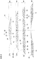
- Fig. 1 shows a cross-section of a part of a pneumatic tire 1 as an embodiment of present invention under its normally inflated unloaded state, taken along a meridian plane of the tire.
- the normally inflated unloaded state is such that the tire is mounted on a standard wheel rim and inflate to a standard pressure but loaded with no tire load.
- the standard wheel rim is a wheel rim officially approved or recommended for the tire by standards organizations, i.e. JATMA (Japan and Asia), T&RA (North America), ETRTO (Europe), TRAA (Australia), STRO (Scandinavia), ALAPA (Latin America), ITTAC (India) and the like which are effective in the area where the tire is manufactured, sold or used.
- the standard pressure is the maximum air pressure for the tire specified by the same organization in the Air-pressure/Maximum-load Table or similar list.
- the standard wheel rim is the "standard rim” specified in JATMA, the “Measuring Rim” in ETRTO, the “Design Rim” in TRA or the like.
- the standard pressure is the “maximum air pressure” in JATMA, the “Inflation Pressure” in ETRTO, the maximum pressure given in the "Tire Load Limits at various cold Inflation Pressures” table in TRA or the like.
- tire radial direction means a direction perpendicular to the tire rotational axis.
- tire axial direction means a direction parallel to the tire rotational axis.
- tire circumferential direction means a circumferential direction around the tire rotational axis.
- the pneumatic tire 1 comprises a tread portion 2, a pair of axially spaced bead portions 4 each with a bead core 5 therein, a pair of sidewall portions 3 extending between tread edges and the bead portions 4, a carcass 6 extending between the bead portions 4, and a tread reinforcing belt 7 disposed radially outside the carcass 6 in the tread portion 2.
- the carcass 6 comprises at least one carcass ply 6A, in the present embodiment, consists of one carcass ply 6A.
- the carcass ply 6A extends between the bead portions 4 through the tread portion 2 and the sidewall portions 3 and is turned up around the bead core 5 in each of the bead portions 4 so as to form a pair of turned-up portions 6b and a main portion 6a therebetween.
- the carcass ply 6A in this example is composed of carcass cords arranged radially at an angle of 75 to 90 degrees with respect to the tire equator C.
- organic fiber cords such as aromatic polyamide, rayon or the like can be suitably employed as the carcass cords.
- the bead portions 4 are each provided with a bead apex rubber 8 disposed between the main portion 6a and the turned-up portion 6b of the carcass ply 6A to extend radially outward from the bead core 5.
- the tread reinforcing belt 7 is composed of at least one ply, in the present embodiment, two cross plies 7A and 7B of belt cords.
- the belt cords of each ply 7A, 7B are arranged parallel with each other at an angle of from 15 to 45 degrees with respect to the tire equator C.
- organic fiber cords such as aromatic polyamide, rayon or the like, or steel cords can be suitably employed as the belt cords.
- each of the sidewall portions 3 is provided, in the outer surface 3s thereof, with a decorative portion 10.
- the decorative portion 10 is defined between two radially spaced circumferential ribs: a radially outer circumferential rib 9a and a radially inner circumferential rib 9b, which protrude from the outer surface of the sidewall portion 3 and extend in the tire circumferential direction.
- circumferential ribs 9a and 9b are however not essential. For example, one of, or both of them may be omitted. Further, instead of the protruding rib, for example, a groove may be used.
- the radial dimension H1 in the tire radial direction (see Fig. 1 ) of the decorative portion 10 is set in a range from 40% to 70% of the cross sectional height H2 of the tire measured from a bead base line BL to a radially outermost point of the tread surface which usually occurs at the tire equator C.
- the radial dimension H1 may be arbitrarily set according to the position of the overlap joint of tire inside structures.
- Fig. 2 is a partial side view of the tire 1 showing an example of the decorative portion 10 formed in the outer surface 3s of the sidewall portion 3.
- the decorative portion 10 extends in the tire circumferential direction in an arc shape.
- the radial dimension H1 is constant in the tire circumferential direction.
- the decorative portion 10 has a circumferential extent ⁇ in terms of an angle around the tire rotation axis as shown in Fig. 2 .
- the circumferential extent ⁇ is set in a range from 60 to 120 degrees.
- a plurality of such decorative portions 10 may be provided in one sidewall portion 3.
- markings such as letters and symbols indicating the tire manufacturer's name, brand name, size, etc. may be formed.
- the decorative portion 10 is formed from a first pattern area 11 and a second pattern area 12.
- the surface of the first pattern area 11 forms a part of the outer surface 3s of the sidewall portion 3
- the surface of the second pattern area 12 forms a part of the outer surface 3s of the sidewall portion 3.
- the surface of the second pattern area 12 has a different surface aspect than the surface of the first pattern area 11.
- the surface aspect is a comprehensive aspect including presence or absence of concavity and convexity, shapes of concavity and convexity, and sizes of concavity and convexity, and when at least one of them is different, these surface aspects are considered as being different from each other.
- Fig. 3 is a perspective view showing an example of the first pattern area 11 and an example of the second pattern area 12.
- One of the first pattern area 11 and the second pattern area 12, which is the first pattern area 11 in the present embodiment, is provided with an uneven surface.
- the uneven surface in this example is formed by providing a plurality of linear pattern elements 13.
- the linear pattern element 13 in this example is a ridge 15.
- the ridges 15 extend radially of the tire rotation axis as shown in Fig. 2 and are arranged in the tire circumference direction.
- grooves 16 are formed between the ridges 15, grooves 16 are formed.
- the grooves 16 also extend radially of the tire rotation axis.
- the ridges 15 are indicated by radial lines, and accordingly, the grooves 16 are spaces between the radial lines.
- the directions of the ridges 15 and the grooves 16 are not limited to the respective radial directions, for example, they may be inclined with respect to the respective radial directions. Further, the inclining directions may be changed between the decorative portions 10 when a plurality of the decorative portions 10 is provided.
- the top surfaces of the ridges 15 are the same level, in other words, the ridges 15 have a same protruding height.
- the ridge 15 in this example has a trapezoidal cross-sectional shape as shown in Fig. 3 although not limited thereto.
- the ridge 15 may have a triangular cross-sectional shape, a semicircular cross-sectional shape, etc.
- the arrangement pitches P1 in the tire circumferential direction between the ridges 15 and the groove depths D1 of the grooves 16 may be set arbitrarily.
- the arrangement pitches P1 in terms of angles around the tire rotation axis can be set in a range from 0.1 to 0.3 degrees.
- the groove depths D1 or the protruding heights of the ridges can be set in a range from 0.2 mm to 0.5 mm.
- the other of the first pattern area 11 and the second pattern area 12, which is the second pattern area 12 in the present embodiment, is provided with a substantially smooth surface 19.
- substantially smooth surface means that the roughness (arithmetic mean roughness Ra) of the surface is not more than 1.0 micrometers.
- the second pattern area 12 having such smooth surface 19 can increase the amount of light reflection and make it brighter and more visible than the first pattern area 11 whose surface is uneven.
- the smooth surface 19 of the second pattern area 12 is the same level as the top surfaces of the ridges 15 of the first pattern area 11, and forms a part of the outer surface 3s of the sidewall portion 3. But, it is also possible that the smooth surface 19 of the second pattern area 12 is the same level as the bottom surfaces of the grooves 16.
- the surface aspect of the first pattern area 11 with the linear pattern elements 13 differs from the surface aspect of the second pattern area 12 with the smooth surface 19. Therefore, the first pattern area 11 and the second pattern area 12 can differ from each other in the amount of light reflection and can increase the contrast between light and dark.
- the decorative portion 10 is virtually-divided into a number N of decorative zones 21 by parallel straight lines, where N is an integer greater than or equal to 3.
- the intervals between the parallel straight lines are constant.
- the parallel straight lines each extend orthogonally to a reference center line 22.
- the reference center line 22 is a straight line passing through the center position 10c in the tire circumferential direction of the decorative portion 10, and the reference center line 22 is parallel with a tire radial direction at the center position 10c.
- the parallel straight lines divide the decorative portion 10 into the number N of equal parts. Accordingly, the decorative zones 21 all have the same dimension W1 in the reference center line 22's direction.
- Fig. 4 shows an example when the number N is 3, namely, the decorative portion 10 is divided into three decorative zones 21.
- the decorative zones 21 include, in the radial direction along the reference center line 22, a radially outermost decorative region, a radially innermost decorative region, and at least one middle decorative region therebetween.
- the three decorative zones 21 are the radially innermost first decorative zone 21a, one middle second decorative zone 21b radially outside thereof, and the radially outermost third decorative zone 21c.
- the decorative zones 21 are virtually divided by the virtual parallel straight lines. But, it is also possible that the decorative zones 21 are actually divided by actual straight lines or linearly extending structures, for example, straight ribs and/or straight grooves (not circumferentially extending ribs or grooves in arc shapes), extending orthogonal to the reference center line 22.
- the percentage of the occupied area of the first pattern area 11 in each of the decorative zones 21 is gradually increased toward the radially outer side of the tire, namely, gradually increased from the radially innermost decorative zone 21a to the radially outermost decorative zone 21c.
- the percentage of the occupied area is the total area of the first pattern area 11 divided by the overall area of the decorative zone 21c and multiplied by 100.
- the occupied area of the markings is excluded from the calculation of the overall area of each decorative zone 21.
- the decorative portion 10 is provided with a pattern which is varied in a certain regularity along the direction of the reference center line 22.
- the decorative zones 21 are changed along the direction of the reference center line 22 with respect to the contrast between the first pattern area 11 and the second pattern area 12.
- the pattern of the decorative portion 10 is varied in three or more steps (by the first to third decorative zones 21a-21c in the present embodiment).
- the tire 1 is provided, in the sidewall portion 3, with a decorative pattern which can present a complex (non-uniform) unique appearance on the tire.
- such decorative pattern may improve the appearance of the tire by itself as well as by making convexoconcave in the sidewall portion 3 unnoticeable, which convexoconcave is caused on the outer surface 3s of the sidewall portion 3 by, for example, overlap jointing of ends of a carcass ply strip and the like.
- the occupied area percentage of the first pattern area 11 from which light reflection is relatively less becomes larger as the decorative zone 21 is positioned outer side in the direction of the reference center line 22,
- the incrementation of the occupied area percentage of the first pattern area 11 is such that, with respect to every two of the radially adjacent decorative zones 21, the occupied area percentage in the radially outer decorative zone 21 is not less than 1.3 times, more preferably not less than 1.4 times, but not more than 3.0 times, more preferably not more than 2.5 times the occupied area percentage in the radially inner decorative zone 21.
- the change in the surface aspect is small, and it becomes difficult to provide a complex decorative pattern on the sidewall portion 3. If more than 3.0 times, the change in the surface aspect may be excessively large which may not be desirable for the appearance.
- the ratio of the occupied area percentage in the radially outer decorative zone 21 to the occupied area percentage in the radially inner decorative zone 21 in a set of two of the radially adjacent decorative zones 21 may be differed from that of another set of two of the radially adjacent decorative zones 21.
- a first ratio of the occupied area percentage of the first pattern area 11 in the second decorative zone 21b to the occupied area percentage of the first pattern area 11 in the first decorative zone 21a is differed from a second ratio of the occupied area percentage of the first pattern area 11 in the third decorative zone 21c to the occupied area percentage of the first pattern area 11 in the second decorative zone 21b.
- the first ratio to be larger than the second ratio, it is possible to make convexoconcave occured in a range from the bead portion 4 to the sidewall portion 3 less noticeable effectively.
- the occupied area percentage of the first pattern area 11 in the radially outermost decorative zone 21 is set in a range from 80% to 100%, more preferably 85% to 100%.
- the percentage of the occupied area of the first pattern area 11 is increased, and convexoconcave occurred in the shoulder portion 24 becomes less noticeable.
- the occupied area percentage of the second pattern area 12 is increased.
- the occupied area percentage of the first pattern area 11 is more preferably not more than 95%
- the occupied area percentage of the first pattern area 11 in the radially innermost decorative zone 21 is set in a range from 30% to 50%, more preferably 35% to 50%.
- the percentage of the occupied area of the first pattern area 11 is increased, and it becomes possible to make convexoconcave occurred in the vicinity of the bead portion 4 less noticeable.
- the occupied area percentage in the radially innermost decorative zone 21 is more than 50%, it becomes difficult to secure effective change in the occupied area percentage between the decorative zones 21. From this point of view, the occupied area percentage of the first pattern area 11 in the radially innermost decorative zone 21 is more preferably set to be not more than 45%.
- the occupied area percentage of the first pattern area 11 in the middle decorative zone or zones 21 is set in a range from 55% to 75%. If more than 75%, it becomes difficult to secure effective change in the occupied area percentage between the radially outermost decorative zone 21 and the middle decorative zone 21. From this point of view, the occupied area percentage in the middle decorative zone or zones 21 is more preferably set to be not more than 70%. On the other hand, if less than 55%, it becomes difficult to secure effective change in the occupied area percentage between the middle decorative zone 21 and the radially inner decorative zone 21.
- the occupied area percentage in the middle decorative zone or zones 21 is more preferably not less than 60%.
- the pattern of the decorative portion 10 is varied effectively from the radially innermost decorative zone 21 (first decorative zone 21a) to the radially outermost decorative zone 21 (third decorative zone 21c) to make the convexoconcave less noticeable.
- the decorative portion 10 may include an inner decorative zone 40, which is positioned on the inner side in the reference center line 22's direction than the radially innermost decorative zone 20 (first decorative zone 21a) of the number N of the decorative zone 20, and which has the same dimension W1 in the reference center line 22's direction as the radially innermost decorative zone 20 (21a).
- the occupied area percentage of the first pattern area 11 in the radially innermost decorative zone 21 (21a) is greater than the occupied area percentage of the first pattern area 11 in the inner decorative zone 40. Accordingly, the occupied area percentage of the first pattern area 11 becomes increased from the inner decorative zone 40 to the radially outermost decorative zone 21 (21c). Therefore, the contrast between the first pattern area 11 and the second pattern area 12 can be effectively varied along the reference center line 22's direction.
- the ratio of the occupied area percentage of the first pattern area 11 in the radially innermost decorative zone 21 (21a) to the occupied area percentage of the first pattern area 11 in the inner decorative zone 40 is not less than 1.3, more preferably not less than 1.4, but not more than 3.0, more preferably not more than 2.5. when there are a plurality of the inner decorative zones 40 on the inner side than the radially innermost decorative zone 20, it is preferable that the occupied area percentage of the first pattern area 11 is increased toward the radially outside in the reference center line 22's direction.
- the first pattern area 11 and the second pattern area 12 are bounded by first boundaries 25 extending parallel to the reference center line 22.
- the sidewall portion 3 is provided with a complex decorative pattern.
- first boundaries 25 extend in the same direction, it becomes easy to machine shaping portions, e.g., convexities, grooves, etc. of a tire vulcanization mold for shaping the first pattern area 11 and the second pattern area 12, which may reduce the increase in the manufacturing time and costs of the tire vulcanization mold.
- the first boundaries 25 are parallel to the reference center line 22. But, the first boundaries 25 are not limited to such arrangement.
- the first boundaries may be arranged so as to extend radially of the tire rotation axis.
- the first pattern area 11 and the second pattern area 12 are also bounded by second boundaries 26 orthogonal to the first boundaries 25.
- the second boundaries 26 have the same length L3, which may effectively suppress the increase in the manufacturing time and costs of the vulcanization mold.
- the decorative portion 10 may include plural kinds of the second boundaries 26 having different lengths L3. such decorative portion 10 makes it possible to give a more complex decorative pattern to the sidewall portion 3.
- the second pattern area 12 in the present embodiment is partitioned into first pattern units 31 and second pattern units 32.
- Each of the first pattern units 31 and the second pattern units 32 at least partially adjoins the first pattern area 11 (linear pattern elements 13) through the first and second boundaries 25 and 26.
- the first pattern unit 31 is defined by two of the first boundaries 25 adjacent to each other in the direction orthogonal to the reference center line 22, and two of the second boundaries 26 connecting between the above-said two of the first boundaries 25 so that the first pattern unit 31 has a substantially rectangular shape as shown in Fig. 5 .
- the second pattern unit 32 is defined by two of the second boundaries 26 extending between two of the first pattern units 31 adjacent to each other in the direction orthogonal to the reference center line 22.
- the above-said two of the second boundaries 26 are spaced apart from both ends of each first pattern unit 31 in the reference center line 22's direction.
- the above-said two of the first pattern units 31 and the second pattern unit 32 therebetween are united and form the substantially H-shaped second pattern area 12.
- the sidewall portion 3 can be provided with a more complex decorative pattern.
- the decorative portion 10 can effectively make convexoconcave occurred in the sidewall portion 3 less noticeable.
- the first and second pattern units 31 and 32 may be arranged with a certain regularity or may be randomly arranged. By randomly arranging the first and second pattern units 31 and 32, the decorative pattern of the sidewall portion 3 can be made more complex.
- the first pattern area 11 may include a third pattern area 33 surrounded by the second pattern area 12 through the first and second boundaries 25 and 26 as shown in Fig. 2 .
- the third pattern area 33 in this example is formed in a substantially rectangular shape as shown in Fig. 2 .
- the decorative portion 10 can make the decorative pattern of the sidewall portion 3 more complex.
- the second boundaries 26 have a length L3, and the first boundaries 25 have lengths L2 some of which are greater than the length L3 of the second boundaries 26.
- some of the first pattern units 31 of the second pattern area 12, and some of the third pattern areas 33 of the first pattern area 11 become longer in the direction of the reference center line 22 than the orthogonal direction to the reference center line 22.
- the decorative portion 10 can provide a decorative pattern for the sidewall portion 3, which is complex but has a certain regularity, thereby further improving the appearance of the tire 1.
- the lengths L2 of the first boundaries 25 are preferably set in a range from 1 to 10 times the length L3 of the second boundaries 26.
- the first pattern unit 31 and the third pattern area 33 become longer in the direction of the reference center line 22.
- the lengths L2 By setting the lengths L2 to be less than 10 times the length L3, it is possible to prevent the first pattern unit 31 and the third pattern area 33 from becoming excessively long, and prevent the decorative pattern from becoming monotonous.
- the lengths L2 are set to be not less than 5 times, but not more than 8 times the length L3.
- the decorative portion 10 since the first boundaries 25 include those having different lengths L2, the decorative portion 10 gives a more complex decorative pattern to the sidewall portion 3. In order to effectively derive such advantageous effect, it is preferred that the first boundaries 25 have four to ten different lengths L2.
- the average value of the lengths L2 of the first boundaries 25 in each decorative zone 21 may be set smaller as the decorative zone 21 is located outer side in a tire radial direction as shown in Fig. 4 .
- the area of the second pattern area 12 becomes smaller as the lengths L2 of the first boundaries 25 become smaller in the present embodiment, the percentage of the occupied area of the first pattern area 11 in the decorative zone 21 becomes increased as the decorative zone 21 is positioned outer side in the tire radial direction. Therefore, the tire 1 in the present embodiment can provide a complex decorative pattern on the sidewall portion 3 to improve the appearance of the tire.
- one of the first pattern area 11 and the second pattern area 12, specifically the first pattern area 11, is provided with the uneven surface formed by the linear pattern elements 13.
- the uneven surface is however, not limited to such linear pattern elements 13.
- Fig. 6 shows another example of the uneven surface.
- the uneven surface is formed by a large number of micro-protrusions 37 protruding perpendicularly to the decorative portion 10.
- the shapes of the micro-protrusions 37 may be circles, ovals, rectangles, triangles or the like. In the example shown in Fig. 6 , the shapes of the micro-protrusions 37 are circles having the same size.
- the decorative portion 10 can increase the contrast of light and dark between the first pattern area 11 and the second pattern area 12.
- Dimensions (protruding height H3 and width/diameter w3 shown in Fig. 6 ) of the micro-protrusions 37 are preferably set in a range from 0.01 mm to 0.3 mm for example, but the dimensions are not limited thereto.
- the uneven surface formed by the micro-protrusions 37 is provided on the first pattern area 11 instead of the former example formed by the linear pattern elements 13, in combination with the smooth surface 19 of the second pattern area 12.
- the first pattern area 11 is provided with the smooth surface 19
- the second pattern area 12 is provided with the uneven surface formed by, for example, the linear pattern elements 13 or the micro-protrusions 37.
- first pattern area 11 and the second pattern area 12 are provided with different uneven surfaces, for example, one of which is formed by the linear pattern elements 13 and the other is formed by the micro-protrusions 37.
- the first pattern area 11 and the second pattern area 12 of the decorative portion 10 are provided with different surface aspects.
- the number N of the decorative zones 21 in the illustrated embodiment is three, the number N can be increased to four or more, for example, in order that the change of the decorative pattern from the radially innermost decorative zone 21 (21a) to the radially outermost decorative zone 21 (21c) becomes more smooth.
- the number N of the decorative zones 21 is excessively large, the manufacturing time and cost of the vulcanization mold may increase, and also there is a possibility that the effect to make the convexoconcave less noticeable is reduced. Therefore, it is preferable that the number N is not more than 10, more preferably not more than 8, still more preferably not more than 5.
- Pneumatic tires of size 225/45ZR18 having the internal structure shown in Fig. 1 were experimentally manufactured as test tires (working example tires Ex.1-Ex.6 and a comparative example tire Ref. 1), changing the decorative zones in the percentage of the occupied area of the first pattern area as shown in Table 1.
- the first pattern area was distributed evenly in the direction of the reference center line so that even if the decorative portion was partitioned into three decorative zones, the percentages of the occupied areas of the first pattern areas had a constant value.
- test tires each had convexoconcave occurred on the outer surface of the sidewall portions due to the overlap jointing of circumferential ends of a carcass ply strip forming the carcass ply.
- Each test tire was evaluated with respect to about whether the convexoconcave was unnoticeable, the appearance of the sidewall portions, and the production cost of the vulcanization mold.
- test methods are as follows.
- One hundred examining staff observed the outer surface of the sidewall portion of each test tire and rated unnoticeableness of the convexoconcave.
- the ratings of the one hundred examining staff were averaged and are indicated in Table 1 by an index based on the undermentioned comparative example tire Ref.2 in Test D being 100, wherein the higher the value, the more the unnoticeable.
- the value is greater than 110, it is difficult to feel the existence of the convexoconcave by touching the outer surface of the sidewall portion with hands.
- the one hundred examining staff observed each test tire from a distance of one meter sideway from the sidewall portion and rated the degree of change in the pattern of the decorative portion and the degree of conspicuousness of the decorative portion.
- the ratings of the one hundred examining staff were averaged and are indicated in Table 1 by an index based on the undermentioned comparative example tire Ref. 2 in Test D being 100, wherein the higher the value, the better the appearance of the decorative portion.
- the values greater than 110 show that the decorative portion is very excellent in the design aspect.
- the time required to produce dies of the tire vulcanization mold for forming the decorative portion was measured.
- the results are indicated in Table 1 by an index based on the undermentioned comparative example tire Ref.2 in Test D being 100, wherein the higher the value, the shorter the production time, wherein the values greater than 80 are acceptable.
- the convexoconcave of the sidewall portions could be made less noticeable, and the appearance of the sidewall portions was improved as compared to the comparative example tire Ref. 1. Further, in the working example tires, the vulcanization mold manufacturing time was fallen in the acceptable range of greater than 80.
- Pneumatic tires of size 225/45ZR18 having the internal structure shown in Fig. 1 were experimentally manufactured as test tires (working example tires Exs. 4 and 7-12), changing the lengths of the first boundaries relative to the length of the second boundaries as shown in Table 2, without changing the percentages of the occupied area of the first pattern areas as follows.
- test tires each had convexoconcave occurred on the outer surface of the sidewall portions due to the overlap jointing of circumferential ends of the carcass ply strip forming the carcass ply.
- Pneumatic tires of size 225/45ZR18 having the internal structure shown in Fig. 1 were experimentally manufactured as test tires (working example tires Exs.4 and 13-15), changing the surface aspects of the first pattern area and the second pattern area as shown in Table 3, and the directions of the first boundaries as follows, without changing the percentages of the occupied area of the first pattern areas.
- the first pattern area and the second pattern area were partitioned by the first boundaries extending parallel to the reference center line.
- the first pattern area and the second pattern area were partitioned by the first boundaries extending radially of the rotational axis of the tire.
- test tires each had convexoconcave occurred on the outer surface of the sidewall portions due to the overlap jointing of circumferential ends of the carcass ply strip forming the carcass ply.
- test tire was evaluated with respect to about whether the convexoconcave was unnoticeable, the appearance of the sidewall portions, and the production cost of the vulcanization mold.
- the test methods were the same as explained above in Test A.
- the test results are shown in Table 3.
- Table 3 Tire Ex.4 Ex.13 Ex.14 Ex.15 first pattern area linear pattern elements smooth micro-protrusions linear pattern elements
- second pattern area smooth linear pattern elements smooth smooth first boundaries parallel parallel parallel radial unnoticeableness 123 115 120 115 appearance 124 120 123 114 manufacturing time 96 96 95 93
- Pneumatic tires of size 225/45ZR18 having the internal structure shown in Fig. 1 were experimentally manufactured as test tires (working example tires Exs.4 and 16-20 and comparative example tire Ref.2), changing the number N of the decorative zones as shown in Table 4, wherein the percentage of the occupied area of the first pattern area in the decorative zone was gradually increased from the radially innermost decorative zone to the radially outermost decorative zone.
- test tires each had convexoconcave occurred on the outer surface of the sidewall portions due to the overlap jointing of circumferential ends of the carcass ply strip forming the carcass ply.
- Test tire was evaluated with respect to about whether the convexoconcave was unnoticeable, the appearance of the sidewall portions, and the production cost of the vulcanization mold.
- the test methods were the same as explained above in Test A.
- the test results are shown in Table 4.
- Table 4 Tire Ref.2 Ex.4 Ex.16 Ex.17 Ex.18 Ex.19 Ex.20 number N of decorative zones 23458910 unnoticeableness 100123134136140145147 appearance 100124130132135138140 manufacturing time 100969392908580
Description
- The present invention relates to a pneumatic tire, more particularly to a decorative portion of a tire sidewall portion.
- In a pneumatic tire, there is a possibility that convexoconcave occurs on the outer surface of the tire especially in the sidewall portions due to the influence of overlap jointing of ends of a carcass ply strip and the like. such convexoconcave does not affect running performance of the tire. However, from an aesthetic point of view, it is desirable that convexoconcave is not noticeable.
- The following patent document 1 discloses a pneumatic tire, wherein the outer surface of the sidewall portion is provided with a decorative portion extending in the tire circumferential direction in order to make convexoconcave occurred on the sidewall portion unnoticeable.
- Patent Document 1:
Japanese Patent Application Publication No. 2004-17828 -
WO 2019/111828 A1 discloses a pneumatic tire comprising the features according to the preamble of claim 1. -
JP 2003 252011 A -
JP H11 321243011 A - The decorative portion disclosed in the patent document 1 exhibits a certain degree of effect on making the convexoconcave on the sidewall portion unnoticeable. In recent years, however, users have demanded further improvements to such effects.
- In view of the above circumstances, the present invention was made, and a primary objective thereof is to provide a pneumatic tire of which appearance can be improved by making convexoconcave on the sidewall portion inconspicuous.
- According to the present invention, a pneumatic tire comprises a sidewall portion having an outer surface provided with a decorative portion extending in the circumferential direction of the tire in an arc shape, wherein
- the decorative portion comprises a first pattern area having a surface aspect, and a second pattern area having a surface aspect different from the surface aspect of the first pattern area, wherein
- when the decorative portion is virtually divided into a number N of decorative zones, N being an integer of 3 or more, by virtual parallel straight lines which are perpendicular to a reference center line which extends in a radial direction of the tire through the center in the tire circumferential direction of the decorative portion when viewed perpendicularly so that, at the position of the reference center line, the decorative portion is divided into the number N equal parts by the parallel straight lines,
- One of the first pattern area and the second pattern area is provided with a plurality of linear pattern elements.
- Alternatively, one of the first pattern area and the second pattern area is provided with micro-protrusions.
- The other of the first pattern area and the second pattern area is provided with a substantially smooth surface.
- The first pattern area and the second pattern area may be bounded by first boundaries extending parallel to the reference center line.
- The first pattern area and the second pattern area may be bounded by second boundaries extending orthogonally to the first boundaries.
- The lengths of the first boundaries may be greater than the length of the second boundaries.
- The lengths of the first boundaries may be not more than 10 times the length of the second boundaries.
- The percentage of the occupied area of the first pattern area in the radially outermost decorative zone may be in a range from 80% to 100%.
- The percentage of the occupied area of the first pattern area in the radially innermost decorative zone may be in a range from 30% to 50%.
- The decorative portion may comprise an inner decorative zone which is located on the inside in a tire radial direction along the reference center line, than a first decorative zone which is the radially innermost one of the number N of the decorative zones, and which has the same dimension in the above-said tire radial direction as the first decorative zone, and
the percentage of the occupied area of the first pattern area in the first decorative zone may be greater than the percentage of the occupied area of the first pattern area in the inner decorative zone. - The decorative zones include a first decorative zone which is innermost in the above-said tire radial direction, a second decorative zone which is located on the outside in the above-said tire radial direction of the first decorative zone, and a third decorative zones which is outermost in the above-said tire radial direction, and
a first quotient of the percentage of the occupied area of the first pattern area in the second decorative zone divided by the percentage of the occupied area of the first pattern area in the first decorative zone may differ from
a second quotient of the percentage of the occupied area of the first pattern area in the third decorative zone divided by the percentage of the occupied area of the first pattern area in the second decorative zone. - Therefore, in the pneumatic tire according to the present invention, the pattern of the decorative portion formed by the first pattern area and the second pattern area is varied in a certain regularity along the direction of the reference center line. Further, the pattern of the decorative portion is varied in three or more steps. Thereby, the pneumatic tire according to the present invention is provided, in the sidewall portion, with a complex (non-uniform) unique decorative pattern, while making convexoconcave of the sidewall portion less noticeable, and the appearance of the tire can be improved.
-
-
Fig. 1 is a cross-sectional partial view of a pneumatic tire as an embodiment of present invention. -
Fig. 2 is a partial side view of the pneumatic tire showing an example of the decorative portion in the outer surface of the sidewall portion. -
Fig. 3 is a perspective view showing an example of the first pattern area and an example of the second pattern area. -
Fig. 4 shows the decorative portion, separating the decorative zones from each other. -
Fig. 5 is an enlarged view of a part of the decorative portion shown inFig. 2 . -
Fig. 6 is a perspective view showing the second pattern area combined with another example of the first pattern area. - The present invention can be applied to pneumatic tires for various vehicles, e.g. passenger cars, heavy duty vehicles such as truck and bus, motorcycles and the like.
- Hereinafter, taking a pneumatic tire for passenger cars as an example, embodiments of the present invention will be described in detail in conjunction with accompanying drawings.
-
Fig. 1 shows a cross-section of a part of a pneumatic tire 1 as an embodiment of present invention under its normally inflated unloaded state, taken along a meridian plane of the tire. - In this application including specification and claims, various dimensions, positions and the like of the tire refer to those under a normally inflated unloaded state of the tire unless otherwise noted.
- The normally inflated unloaded state is such that the tire is mounted on a standard wheel rim and inflate to a standard pressure but loaded with no tire load.
- The standard wheel rim is a wheel rim officially approved or recommended for the tire by standards organizations, i.e. JATMA (Japan and Asia), T&RA (North America), ETRTO (Europe), TRAA (Australia), STRO (Scandinavia), ALAPA (Latin America), ITTAC (India) and the like which are effective in the area where the tire is manufactured, sold or used.
- The standard pressure is the maximum air pressure for the tire specified by the same organization in the Air-pressure/Maximum-load Table or similar list.
- For example, the standard wheel rim is the "standard rim" specified in JATMA, the "Measuring Rim" in ETRTO, the "Design Rim" in TRA or the like. The standard pressure is the "maximum air pressure" in JATMA, the "Inflation Pressure" in ETRTO, the maximum pressure given in the "Tire Load Limits at various cold Inflation Pressures" table in TRA or the like.
- The term "tire radial direction" means a direction perpendicular to the tire rotational axis.
- The term "tire axial direction" means a direction parallel to the tire rotational axis.
- The term "tire circumferential direction" means a circumferential direction around the tire rotational axis.
- The pneumatic tire 1 comprises a
tread portion 2, a pair of axially spacedbead portions 4 each with abead core 5 therein, a pair ofsidewall portions 3 extending between tread edges and thebead portions 4, acarcass 6 extending between thebead portions 4, and atread reinforcing belt 7 disposed radially outside thecarcass 6 in thetread portion 2. - The
carcass 6 comprises at least onecarcass ply 6A, in the present embodiment, consists of onecarcass ply 6A. - The
carcass ply 6A extends between thebead portions 4 through thetread portion 2 and thesidewall portions 3 and is turned up around thebead core 5 in each of thebead portions 4 so as to form a pair of turned-upportions 6b and amain portion 6a therebetween. Thecarcass ply 6A in this example is composed of carcass cords arranged radially at an angle of 75 to 90 degrees with respect to the tire equator C. For example, organic fiber cords such as aromatic polyamide, rayon or the like can be suitably employed as the carcass cords. - The
bead portions 4 are each provided with abead apex rubber 8 disposed between themain portion 6a and the turned-upportion 6b of thecarcass ply 6A to extend radially outward from thebead core 5. - The
tread reinforcing belt 7 is composed of at least one ply, in the present embodiment, twocross plies ply - At least one of, in the present embodiment, each of the
sidewall portions 3 is provided, in the outer surface 3s thereof, with adecorative portion 10. - In the present embodiment, the
decorative portion 10 is defined between two radially spaced circumferential ribs: a radially outercircumferential rib 9a and a radially innercircumferential rib 9b, which protrude from the outer surface of thesidewall portion 3 and extend in the tire circumferential direction. - such
circumferential ribs - In the present embodiment, the radial dimension H1 in the tire radial direction (see
Fig. 1 ) of thedecorative portion 10 is set in a range from 40% to 70% of the cross sectional height H2 of the tire measured from a bead base line BL to a radially outermost point of the tread surface which usually occurs at the tire equator C. However, the radial dimension H1 may be arbitrarily set according to the position of the overlap joint of tire inside structures. -
Fig. 2 is a partial side view of the tire 1 showing an example of thedecorative portion 10 formed in the outer surface 3s of thesidewall portion 3. - As shown, the
decorative portion 10 extends in the tire circumferential direction in an arc shape. - In the present embodiment, the radial dimension H1 is constant in the tire circumferential direction.
- In the present embodiment, the
decorative portion 10 has a circumferential extent α in terms of an angle around the tire rotation axis as shown inFig. 2 . For example, the circumferential extent α is set in a range from 60 to 120 degrees. - A plurality of such
decorative portions 10 may be provided in onesidewall portion 3. - In the
decorative portion 10, markings such as letters and symbols indicating the tire manufacturer's name, brand name, size, etc. may be formed. - The
decorative portion 10 is formed from afirst pattern area 11 and asecond pattern area 12. - The surface of the
first pattern area 11 forms a part of the outer surface 3s of thesidewall portion 3, and the surface of thesecond pattern area 12 forms a part of the outer surface 3s of thesidewall portion 3. - The surface of the
second pattern area 12 has a different surface aspect than the surface of thefirst pattern area 11. - Here, the surface aspect is a comprehensive aspect including presence or absence of concavity and convexity, shapes of concavity and convexity, and sizes of concavity and convexity, and when at least one of them is different, these surface aspects are considered as being different from each other.
-
Fig. 3 is a perspective view showing an example of thefirst pattern area 11 and an example of thesecond pattern area 12. - One of the
first pattern area 11 and thesecond pattern area 12, which is thefirst pattern area 11 in the present embodiment, is provided with an uneven surface. - The uneven surface in this example is formed by providing a plurality of
linear pattern elements 13. - The
linear pattern element 13 in this example is aridge 15. In the present embodiment, theridges 15 extend radially of the tire rotation axis as shown inFig. 2 and are arranged in the tire circumference direction. Thus, between theridges 15,grooves 16 are formed. Thegrooves 16 also extend radially of the tire rotation axis. - In
Fig. 2 , theridges 15 are indicated by radial lines, and accordingly, thegrooves 16 are spaces between the radial lines. The directions of theridges 15 and thegrooves 16 are not limited to the respective radial directions, for example, they may be inclined with respect to the respective radial directions. Further, the inclining directions may be changed between thedecorative portions 10 when a plurality of thedecorative portions 10 is provided. - In the
linear pattern element 13 in the present embodiment, the top surfaces of theridges 15 are the same level, in other words, theridges 15 have a same protruding height. - In the cross section of the
ridge 15 taken perpendicularly to the longitudinal direction thereof, theridge 15 in this example has a trapezoidal cross-sectional shape as shown inFig. 3 although not limited thereto. Theridge 15 may have a triangular cross-sectional shape, a semicircular cross-sectional shape, etc. - The arrangement pitches P1 in the tire circumferential direction between the
ridges 15 and the groove depths D1 of thegrooves 16 may be set arbitrarily. For example, the arrangement pitches P1 in terms of angles around the tire rotation axis can be set in a range from 0.1 to 0.3 degrees. - For example, the groove depths D1 or the protruding heights of the ridges can be set in a range from 0.2 mm to 0.5 mm.
- The other of the
first pattern area 11 and thesecond pattern area 12, which is thesecond pattern area 12 in the present embodiment, is provided with a substantiallysmooth surface 19. - Here, the "substantially smooth surface" means that the roughness (arithmetic mean roughness Ra) of the surface is not more than 1.0 micrometers.
- The
second pattern area 12 having suchsmooth surface 19 can increase the amount of light reflection and make it brighter and more visible than thefirst pattern area 11 whose surface is uneven. - In the present embodiment, the
smooth surface 19 of thesecond pattern area 12 is the same level as the top surfaces of theridges 15 of thefirst pattern area 11, and forms a part of the outer surface 3s of thesidewall portion 3. But, it is also possible that thesmooth surface 19 of thesecond pattern area 12 is the same level as the bottom surfaces of thegrooves 16. - By the uneven surface formed by the
linear pattern elements 13 and thesmooth surface 19, the surface aspect of thefirst pattern area 11 with thelinear pattern elements 13 differs from the surface aspect of thesecond pattern area 12 with thesmooth surface 19. Therefore, thefirst pattern area 11 and thesecond pattern area 12 can differ from each other in the amount of light reflection and can increase the contrast between light and dark. - The
decorative portion 10 is virtually-divided into a number N ofdecorative zones 21 by parallel straight lines, where N is an integer greater than or equal to 3. The intervals between the parallel straight lines are constant. The parallel straight lines each extend orthogonally to areference center line 22. Thereference center line 22 is a straight line passing through thecenter position 10c in the tire circumferential direction of thedecorative portion 10, and thereference center line 22 is parallel with a tire radial direction at thecenter position 10c. - Along the
reference center line 22, namely, at the position of thereference center line 22, the parallel straight lines divide thedecorative portion 10 into the number N of equal parts. Accordingly, thedecorative zones 21 all have the same dimension W1 in thereference center line 22's direction. -
Fig. 4 shows an example when the number N is 3, namely, thedecorative portion 10 is divided into threedecorative zones 21. - The
decorative zones 21 include, in the radial direction along thereference center line 22, a radially outermost decorative region, a radially innermost decorative region, and at least one middle decorative region therebetween. - In the present embodiment, the three
decorative zones 21 are the radially innermost firstdecorative zone 21a, one middle seconddecorative zone 21b radially outside thereof, and the radially outermost thirddecorative zone 21c. - In the present embodiment, as explained above, the decorative zones 21 (21a-21c) are virtually divided by the virtual parallel straight lines. But, it is also possible that the
decorative zones 21 are actually divided by actual straight lines or linearly extending structures, for example, straight ribs and/or straight grooves (not circumferentially extending ribs or grooves in arc shapes), extending orthogonal to thereference center line 22. - In the present embodiment, the percentage of the occupied area of the
first pattern area 11 in each of thedecorative zones 21 is gradually increased toward the radially outer side of the tire, namely, gradually increased from the radially innermostdecorative zone 21a to the radially outermostdecorative zone 21c. - Incidentally, the percentage of the occupied area is the total area of the
first pattern area 11 divided by the overall area of thedecorative zone 21c and multiplied by 100. However, when the above-mentioned markings are provided in thedecorative portion 10, the occupied area of the markings is excluded from the calculation of the overall area of eachdecorative zone 21. - In the present embodiment, as the percentage of the occupied area of the
first pattern area 11 is varied as described above, thedecorative portion 10 is provided with a pattern which is varied in a certain regularity along the direction of thereference center line 22. - specifically, in the
decorative portion 10 in the present embodiment, thedecorative zones 21 are changed along the direction of thereference center line 22 with respect to the contrast between thefirst pattern area 11 and thesecond pattern area 12. - Further, the pattern of the
decorative portion 10 is varied in three or more steps (by the first to thirddecorative zones 21a-21c in the present embodiment). Thereby, the tire 1 is provided, in thesidewall portion 3, with a decorative pattern which can present a complex (non-uniform) unique appearance on the tire. such decorative pattern may improve the appearance of the tire by itself as well as by making convexoconcave in thesidewall portion 3 unnoticeable, which convexoconcave is caused on the outer surface 3s of thesidewall portion 3 by, for example, overlap jointing of ends of a carcass ply strip and the like. - In the
decorative portion 10 in the present embodiment, since the occupied area percentage of thefirst pattern area 11 from which light reflection is relatively less, becomes larger as thedecorative zone 21 is positioned outer side in the direction of thereference center line 22, - if the tire is such that the above-mentioned convexoconcave of the
sidewall portion 3 is more likely to occur near the shoulder portion 24 (or the radially outermost part of the sidewall portion as shown inFigs. 1 and2 ), - it is effective to position the
reference center line 22 at a position in the tire circumferential direction where the convexoconcave is liable to occur. This makes it possible to more effectively disguise the convexoconcave. - It is preferable that the incrementation of the occupied area percentage of the
first pattern area 11 is such that, with respect to every two of the radially adjacentdecorative zones 21, the occupied area percentage in the radially outerdecorative zone 21 is not less than 1.3 times, more preferably not less than 1.4 times, but not more than 3.0 times, more preferably not more than 2.5 times the occupied area percentage in the radially innerdecorative zone 21. - If less than 1.3 times, the change in the surface aspect is small, and it becomes difficult to provide a complex decorative pattern on the
sidewall portion 3. If more than 3.0 times, the change in the surface aspect may be excessively large which may not be desirable for the appearance. - Further, the ratio of the occupied area percentage in the radially outer
decorative zone 21 to the occupied area percentage in the radially innerdecorative zone 21 in a set of two of the radially adjacentdecorative zones 21 may be differed from that of another set of two of the radially adjacentdecorative zones 21. - More specifically, in the present embodiment, a first ratio of the occupied area percentage of the
first pattern area 11 in the seconddecorative zone 21b to the occupied area percentage of thefirst pattern area 11 in the firstdecorative zone 21a is differed from a second ratio of the occupied area percentage of thefirst pattern area 11 in the thirddecorative zone 21c to the occupied area percentage of thefirst pattern area 11 in the seconddecorative zone 21b. - Thereby, a change of the decorative pattern from the first
decorative zone 21a to the seconddecorative zone 21b becomes different from a change of the decorative pattern from the seconddecorative zone 21b to the thirddecorative zone 21c. Therefore, it is possible to give a more complex decorative pattern to thesidewall portion 3. - For example, by setting the first ratio to be larger than the second ratio, it is possible to make convexoconcave occured in a range from the
bead portion 4 to thesidewall portion 3 less noticeable effectively. - Preferably, the occupied area percentage of the
first pattern area 11 in the radially outermost decorative zone 21 (thirddecorative zone 21c) is set in a range from 80% to 100%, more preferably 85% to 100%. Thereby, in the vicinity of the above-saidshoulder portion 24, the percentage of the occupied area of thefirst pattern area 11 is increased, and convexoconcave occurred in theshoulder portion 24 becomes less noticeable. - On the other hand, by decreasing the occupied area percentage of the
first pattern area 11 within the above ranges, the occupied area percentage of thesecond pattern area 12 is increased. - This makes it possible to give a complex decorative pattern to the
sidewall portion 3. - From this point of view, the occupied area percentage of the
first pattern area 11 is more preferably not more than 95%, - Preferably, the occupied area percentage of the
first pattern area 11 in the radially innermost decorative zone 21 (firstdecorative zone 21a) is set in a range from 30% to 50%, more preferably 35% to 50%. Thereby, in the vicinity of thebead portion 4, the percentage of the occupied area of thefirst pattern area 11 is increased, and it becomes possible to make convexoconcave occurred in the vicinity of thebead portion 4 less noticeable. - If the occupied area percentage in the radially innermost
decorative zone 21 is more than 50%, it becomes difficult to secure effective change in the occupied area percentage between thedecorative zones 21. From this point of view, the occupied area percentage of thefirst pattern area 11 in the radially innermostdecorative zone 21 is more preferably set to be not more than 45%. - Preferably, the occupied area percentage of the
first pattern area 11 in the middle decorative zone or zones 21 (seconddecorative zone 21b) is set in a range from 55% to 75%. If more than 75%, it becomes difficult to secure effective change in the occupied area percentage between the radially outermostdecorative zone 21 and the middledecorative zone 21. From this point of view, the occupied area percentage in the middle decorative zone orzones 21 is more preferably set to be not more than 70%. On the other hand, if less than 55%, it becomes difficult to secure effective change in the occupied area percentage between the middledecorative zone 21 and the radially innerdecorative zone 21. - From this point of view, the occupied area percentage in the middle decorative zone or
zones 21 is more preferably not less than 60%. Thereby, the pattern of thedecorative portion 10 is varied effectively from the radially innermost decorative zone 21 (firstdecorative zone 21a) to the radially outermost decorative zone 21 (thirddecorative zone 21c) to make the convexoconcave less noticeable. - As shown in
Fig. 4 , thedecorative portion 10 may include an innerdecorative zone 40, which is positioned on the inner side in thereference center line 22's direction than the radially innermost decorative zone 20 (firstdecorative zone 21a) of the number N of the decorative zone 20, and which has the same dimension W1 in thereference center line 22's direction as the radially innermost decorative zone 20 (21a). - In this case, it is preferable that the occupied area percentage of the
first pattern area 11 in the radially innermost decorative zone 21 (21a) is greater than the occupied area percentage of thefirst pattern area 11 in the innerdecorative zone 40. Accordingly, the occupied area percentage of thefirst pattern area 11 becomes increased from the innerdecorative zone 40 to the radially outermost decorative zone 21 (21c). Therefore, the contrast between thefirst pattern area 11 and thesecond pattern area 12 can be effectively varied along thereference center line 22's direction. - Preferably, the ratio of the occupied area percentage of the
first pattern area 11 in the radially innermost decorative zone 21 (21a) to the occupied area percentage of thefirst pattern area 11 in the innerdecorative zone 40 is not less than 1.3, more preferably not less than 1.4, but not more than 3.0, more preferably not more than 2.5.
when there are a plurality of the innerdecorative zones 40 on the inner side than the radially innermost decorative zone 20, it is preferable that the occupied area percentage of thefirst pattern area 11 is increased toward the radially outside in thereference center line 22's direction. - In the
decorative portion 10 in the present embodiment, as shown inFig. 5 , thefirst pattern area 11 and thesecond pattern area 12 are bounded byfirst boundaries 25 extending parallel to thereference center line 22. - Therefore, at least some of the
first boundaries 25 intersect with theridges 15 andgrooves 16 which extend radially of the tire rotation axis. As a result, thesidewall portion 3 is provided with a complex decorative pattern. - Further, since the
first boundaries 25 extend in the same direction, it becomes easy to machine shaping portions, e.g., convexities, grooves, etc. of a tire vulcanization mold for shaping thefirst pattern area 11 and thesecond pattern area 12, which may reduce the increase in the manufacturing time and costs of the tire vulcanization mold. - In the present embodiment, the
first boundaries 25 are parallel to thereference center line 22. But, thefirst boundaries 25 are not limited to such arrangement. For example, the first boundaries may be arranged so as to extend radially of the tire rotation axis. - In the
decorative portion 10 in the present embodiment, in addition to thefirst boundaries 25, thefirst pattern area 11 and thesecond pattern area 12 are also bounded bysecond boundaries 26 orthogonal to thefirst boundaries 25. - since the
second boundaries 26 extend in the same direction, the increase in the manufacturing time and costs of the tire vulcanization mold may be suppressed. - In the present embodiment, the
second boundaries 26 have the same length L3, which may effectively suppress the increase in the manufacturing time and costs of the vulcanization mold. - The
decorative portion 10 may include plural kinds of thesecond boundaries 26 having different lengths L3. suchdecorative portion 10 makes it possible to give a more complex decorative pattern to thesidewall portion 3. - By the
first boundaries 25 and thesecond boundaries 26, thesecond pattern area 12 in the present embodiment is partitioned intofirst pattern units 31 andsecond pattern units 32. Each of thefirst pattern units 31 and thesecond pattern units 32 at least partially adjoins the first pattern area 11 (linear pattern elements 13) through the first andsecond boundaries - The
first pattern unit 31 is defined by two of thefirst boundaries 25 adjacent to each other in the direction orthogonal to thereference center line 22, and two of thesecond boundaries 26 connecting between the above-said two of thefirst boundaries 25 so that thefirst pattern unit 31 has a substantially rectangular shape as shown inFig. 5 . - The
second pattern unit 32 is defined by two of thesecond boundaries 26 extending between two of thefirst pattern units 31 adjacent to each other in the direction orthogonal to thereference center line 22. The above-said two of thesecond boundaries 26 are spaced apart from both ends of eachfirst pattern unit 31 in thereference center line 22's direction. The above-said two of thefirst pattern units 31 and thesecond pattern unit 32 therebetween are united and form the substantially H-shapedsecond pattern area 12. - since the
decorative portion 10 in the present embodiment is provided with thefirst pattern units 31 and thesecond pattern units 32 as thesecond pattern area 12, thesidewall portion 3 can be provided with a more complex decorative pattern. Thus, thedecorative portion 10 can effectively make convexoconcave occurred in thesidewall portion 3 less noticeable. - The first and
second pattern units second pattern units sidewall portion 3 can be made more complex. - The
first pattern area 11 may include athird pattern area 33 surrounded by thesecond pattern area 12 through the first andsecond boundaries Fig. 2 . - The
third pattern area 33 in this example is formed in a substantially rectangular shape as shown inFig. 2 . - By providing such
third pattern areas 33, thedecorative portion 10 can make the decorative pattern of thesidewall portion 3 more complex. - In the present embodiment, the
second boundaries 26 have a length L3, and thefirst boundaries 25 have lengths L2 some of which are greater than the length L3 of thesecond boundaries 26. As a result, as shown inFig. 5 , some of thefirst pattern units 31 of thesecond pattern area 12, and some of thethird pattern areas 33 of thefirst pattern area 11 become longer in the direction of thereference center line 22 than the orthogonal direction to thereference center line 22. - Thereby, the
decorative portion 10 can provide a decorative pattern for thesidewall portion 3, which is complex but has a certain regularity, thereby further improving the appearance of the tire 1. - In order to effectively derive such advantageous effect, the lengths L2 of the
first boundaries 25 are preferably set in a range from 1 to 10 times the length L3 of thesecond boundaries 26. - By setting the lengths L2 to be greater than the length L3, the
first pattern unit 31 and thethird pattern area 33 become longer in the direction of thereference center line 22. - By setting the lengths L2 to be less than 10 times the length L3, it is possible to prevent the
first pattern unit 31 and thethird pattern area 33 from becoming excessively long, and prevent the decorative pattern from becoming monotonous. - In view of this, it is preferred that the lengths L2 are set to be not less than 5 times, but not more than 8 times the length L3.
- In the
decorative portion 10 in the present embodiment, since thefirst boundaries 25 include those having different lengths L2, thedecorative portion 10 gives a more complex decorative pattern to thesidewall portion 3. In order to effectively derive such advantageous effect, it is preferred that thefirst boundaries 25 have four to ten different lengths L2. - The average value of the lengths L2 of the
first boundaries 25 in eachdecorative zone 21 may be set smaller as thedecorative zone 21 is located outer side in a tire radial direction as shown inFig. 4 . This gives further variations to the pattern of thedecorative portion 10 in the tire radial direction. Furthermore, since the area of thesecond pattern area 12 becomes smaller as the lengths L2 of thefirst boundaries 25 become smaller in the present embodiment, the percentage of the occupied area of thefirst pattern area 11 in thedecorative zone 21 becomes increased as thedecorative zone 21 is positioned outer side in the tire radial direction. Therefore, the tire 1 in the present embodiment can provide a complex decorative pattern on thesidewall portion 3 to improve the appearance of the tire. - In the present embodiment, one of the
first pattern area 11 and thesecond pattern area 12, specifically thefirst pattern area 11, is provided with the uneven surface formed by thelinear pattern elements 13. The uneven surface is however, not limited to suchlinear pattern elements 13. -
Fig. 6 shows another example of the uneven surface. - In this example, the uneven surface is formed by a large number of
micro-protrusions 37 protruding perpendicularly to thedecorative portion 10. when thedecorative portion 10 is viewed perpendicularly thereto, the shapes of the micro-protrusions 37 may be circles, ovals, rectangles, triangles or the like. In the example shown inFig. 6 , the shapes of the micro-protrusions 37 are circles having the same size. - similarly to the
linear pattern elements 13, such micro-protrusions can reduce the amount of light reflection as compared to thesmooth surface 19. Therefore, thedecorative portion 10 can increase the contrast of light and dark between thefirst pattern area 11 and thesecond pattern area 12. Dimensions (protruding height H3 and width/diameter w3 shown inFig. 6 ) of the micro-protrusions 37 are preferably set in a range from 0.01 mm to 0.3 mm for example, but the dimensions are not limited thereto. - The uneven surface formed by the micro-protrusions 37 is provided on the
first pattern area 11 instead of the former example formed by thelinear pattern elements 13, in combination with thesmooth surface 19 of thesecond pattern area 12. - As another embodiment of the present invention, it is also possible that the
first pattern area 11 is provided with thesmooth surface 19, and thesecond pattern area 12 is provided with the uneven surface formed by, for example, thelinear pattern elements 13 or the micro-protrusions 37. - As still another embodiment of the present invention, it is also possible that the
first pattern area 11 and thesecond pattern area 12 are provided with different uneven surfaces, for example, one of which is formed by thelinear pattern elements 13 and the other is formed by the micro-protrusions 37. - Anyway, according to the present invention, the
first pattern area 11 and thesecond pattern area 12 of thedecorative portion 10 are provided with different surface aspects. - Although the number N of the
decorative zones 21 in the illustrated embodiment is three, the number N can be increased to four or more, for example, in order that the change of the decorative pattern from the radially innermost decorative zone 21 (21a) to the radially outermost decorative zone 21 (21c) becomes more smooth. However, if the number N of thedecorative zones 21 is excessively large, the manufacturing time and cost of the vulcanization mold may increase, and also there is a possibility that the effect to make the convexoconcave less noticeable is reduced. Therefore, it is preferable that the number N is not more than 10, more preferably not more than 8, still more preferably not more than 5. - while detailed description has been made of preferable embodiments of the present invention, the present invention can be embodied in various forms without being limited to the illustrated embodiments.
- Pneumatic tires of size 225/45ZR18 having the internal structure shown in
Fig. 1 were experimentally manufactured as test tires (working example tires Ex.1-Ex.6 and a comparative example tire Ref. 1), changing the decorative zones in the percentage of the occupied area of the first pattern area as shown in Table 1. - In the working example tires Ex.1-Ex.6, when each decorative portion was partitioned into three decorative zones, the percentage of the occupied area of the first pattern area was increased from the radially innermost decorative zone to the radially outermost decorative zone.
- On the other hand, in the decorative portion of the comparative example tire Ref. 1, the first pattern area was distributed evenly in the direction of the reference center line so that even if the decorative portion was partitioned into three decorative zones, the percentages of the occupied areas of the first pattern areas had a constant value.
- The common specifications are as follows:
- First pattern area:
- uneven surface formed by linear pattern elements (ridges) arrangement pitches P1 of ridges: 0.14 degrees
- groove depths D1: 0.3 mm
- second pattern area:
smooth surface - First boundaries: parallel to reference center line
- First boundaries' lengths: 1 to 5 times second boundaries' length
- The test tires each had convexoconcave occurred on the outer surface of the sidewall portions due to the overlap jointing of circumferential ends of a carcass ply strip forming the carcass ply.
- Each test tire was evaluated with respect to about whether the convexoconcave was unnoticeable, the appearance of the sidewall portions, and the production cost of the vulcanization mold.
- The test methods are as follows.
- One hundred examining staff observed the outer surface of the sidewall portion of each test tire and rated unnoticeableness of the convexoconcave. The ratings of the one hundred examining staff were averaged and are indicated in Table 1 by an index based on the undermentioned comparative example tire Ref.2 in Test D being 100, wherein the higher the value, the more the unnoticeable. Incidentally, when the value is greater than 110, it is difficult to feel the existence of the convexoconcave by touching the outer surface of the sidewall portion with hands.
- The one hundred examining staff observed each test tire from a distance of one meter sideway from the sidewall portion and rated the degree of change in the pattern of the decorative portion and the degree of conspicuousness of the decorative portion. The ratings of the one hundred examining staff were averaged and are indicated in Table 1 by an index based on the undermentioned comparative example tire Ref. 2 in Test D being 100, wherein the higher the value, the better the appearance of the decorative portion. Incidentally, the values greater than 110 show that the decorative portion is very excellent in the design aspect.
- The time required to produce dies of the tire vulcanization mold for forming the decorative portion was measured. The results are indicated in Table 1 by an index based on the undermentioned comparative example tire Ref.2 in Test D being 100, wherein the higher the value, the shorter the production time, wherein the values greater than 80 are acceptable.
Table 1 Tire Ref.1 Ex.1 Ex.2 Ex.3 Ex.4 Ex.5 Ex.6 decorative zone number N - 3 3 3 3 3 3 percentage of the occupied area of first pattern area first decorative zone 50 20 25 30 35 40 50 second decorative zone 50 45 50 55 60 65 75 third decorative zone 50 70 75 80 85 90 100 first ratio 1 2.25 2.00 1.83 1.71 1.63 1.50 second ratio 1 1.56 1.50 1.45 1.42 1.38 1.33 unnoticeableness 90 113 120 123 130 138 125 appearance 85 114 121 124 132 137 124 manufacturing time 110 96 96 96 95 93 95 - From the test results, it was confirmed that, in the working example tires, the convexoconcave of the sidewall portions could be made less noticeable, and the appearance of the sidewall portions was improved as compared to the comparative example tire Ref. 1. Further, in the working example tires, the vulcanization mold manufacturing time was fallen in the acceptable range of greater than 80.
- Pneumatic tires of size 225/45ZR18 having the internal structure shown in
Fig. 1 were experimentally manufactured as test tires (working example tires Exs. 4 and 7-12), changing the lengths of the first boundaries relative to the length of the second boundaries as shown in Table 2, without changing the percentages of the occupied area of the first pattern areas as follows. - The common specifications are as follows:
- First pattern area:
- uneven surface formed by linear pattern elements (ridges) arrangement pitches P1 of ridges: 0.14 degrees
- groove depth D1: 0.3 mm
- second pattern area:
smooth surface - First boundaries: parallel to reference center line
- Decorative zones: N=3
- Percentage of occupied area of first pattern area
- first decorative zone: 30%
- second decorative zone: 55%
- third decorative zone: 80%
- The test tires each had convexoconcave occurred on the outer surface of the sidewall portions due to the overlap jointing of circumferential ends of the carcass ply strip forming the carcass ply.
- Each test tire was evaluated with respect to about whether the convexoconcave was unnoticeable, the appearance of the sidewall portions, and the production cost of the vulcanization mold. The test methods were the same as explained above in Test A. The test results are shown in Table 2.
Table 2 Tire Ex.7 Ex.8 Ex.4 Ex.9 Ex.10 Ex.11 Ex.12 first boundaries' lengths relative to second boundaries' length (times) 1-3 1-4 1-5 1-6 1-8 1-10 1-12 unnoticeableness 109 118 123 126 129 120 115 appearance 108 120 124 125 126 121 118 manufacturing time 98 97 96 96 95 96 95 - From the test results, it was confirmed that, in the working example tires, the convexoconcave of the sidewall portions could be made less noticeable, and the appearance of the sidewall portions was improved as compared to the comparative example tire Ref.1 in Test A. Further, in the working example tires, the vulcanization mold manufacturing time was fallen in the acceptable range of greater than 80.
- Pneumatic tires of size 225/45ZR18 having the internal structure shown in
Fig. 1 were experimentally manufactured as test tires (working example tires Exs.4 and 13-15), changing the surface aspects of the first pattern area and the second pattern area as shown in Table 3, and the directions of the first boundaries as follows, without changing the percentages of the occupied area of the first pattern areas. - In the working example tires Exs. 4, 13 and 14, the first pattern area and the second pattern area were partitioned by the first boundaries extending parallel to the reference center line. In the working example tire Ex. 15, the first pattern area and the second pattern area were partitioned by the first boundaries extending radially of the rotational axis of the tire.
- The common specifications are as follows
- Uneven surface
- formed by linear patterns (ridges)
- arrangement pitches P1 of ridges: 0.14 degrees
- groove depth D1: 0.3 mm
- First boundaries' lengths: 1 to 5 times second boundaries' length
- Decorative zones: N=3
- Percentage of occupied area of first pattern area
- first decorative zone: 30%
- second decorative zone: 55%
- third decorative zone: 80%
- The test tires each had convexoconcave occurred on the outer surface of the sidewall portions due to the overlap jointing of circumferential ends of the carcass ply strip forming the carcass ply.
- Each test tire was evaluated with respect to about whether the convexoconcave was unnoticeable, the appearance of the sidewall portions, and the production cost of the vulcanization mold. The test methods were the same as explained above in Test A. The test results are shown in Table 3.
Table 3 Tire Ex.4 Ex.13 Ex.14 Ex.15 first pattern area linear pattern elements smooth micro-protrusions linear pattern elements second pattern area smooth linear pattern elements smooth smooth first boundaries parallel parallel parallel radial unnoticeableness 123 115 120 115 appearance 124 120 123 114 manufacturing time 96 96 95 93 - From the test results, it was confirmed that, in the working example tires, the convexoconcave of the sidewall portions could be made less noticeable, and the appearance of the sidewall portions was improved as compared to the comparative example tire Ref.1 in Test A. Further, in the working example tires, the vulcanization mold manufacturing time was fallen in the acceptable range of greater than 80.
- Pneumatic tires of size 225/45ZR18 having the internal structure shown in
Fig. 1 were experimentally manufactured as test tires (working example tires Exs.4 and 16-20 and comparative example tire Ref.2), changing the number N of the decorative zones as shown in Table 4, wherein the percentage of the occupied area of the first pattern area in the decorative zone was gradually increased from the radially innermost decorative zone to the radially outermost decorative zone. - The common specifications are as follows
- First pattern area:
- uneven surface formed by linear pattern elements (ridges)
- arrangement pitches P1 of ridges: 0.14 degrees
- groove depth D1: 0.3 mm
- second pattern area:
smooth surface - First boundaries: parallel to reference center line
- First boundaries' lengths: 1 to 5 times second boundaries' length
- Percentage of occupied area of first pattern area
- radially innermost decorative zone: 30%
- radially outermost decorative zone: 80%
- The test tires each had convexoconcave occurred on the outer surface of the sidewall portions due to the overlap jointing of circumferential ends of the carcass ply strip forming the carcass ply.
- Each test tire was evaluated with respect to about whether the convexoconcave was unnoticeable, the appearance of the sidewall portions, and the production cost of the vulcanization mold. The test methods were the same as explained above in Test A. The test results are shown in Table 4.
Table 4 Tire Ref.2 Ex.4 Ex.16 Ex.17 Ex.18 Ex.19 Ex.20 number N of decorative zones 23458910 unnoticeableness 100123134136140145147 appearance 100124130132135138140 manufacturing time 100969392908580 - From the test results, it was confirmed that, in the working example tires, the convexoconcave of the sidewall portions could be made less noticeable, and the appearance of the sidewall portions was improved as compared to the comparative example tire Ref.2 and the comparative example tire Ref.1 in Test A. Further, in the working example tires, the vulcanization mold manufacturing time was fallen in the acceptable range of greater than 80.
-
- 1
- pneumatic tire
- 3
- sidewall portion
- 10
- decorative portion
- 11
- first pattern area
- 12
- second pattern area
- 21
- decorative zone
- 22
- reference center line
Claims (9)
- A pneumatic tire (1) comprising:a sidewall portion (3) having an outer surface (3S) provided with a decorative portion (10) extending in the circumferential direction of the tire (1) in an arc shape, whereinthe decorative portion (10) comprises a first pattern area (11) having a surface aspect, and a second pattern area (12) having a surface aspect different from the surface aspect of the first pattern area (11), whereinwhen the decorative portion (10) is virtually divided into a number N of decorative zones (21), N being an integer of 3 or more, by virtual parallel straight lines which are perpendicular to a reference center line (22) which extends in a radial direction of the tire (1) through the center (10c) in the tire circumferential direction of the decorative portion (10) when viewed perpendicularly so that, at the position of the reference center line (22), the decorative portion (10) is divided into the number N equal parts by the virtual parallel straight lines, andpercentages of occupied area of the first pattern area (11) in the respective decorative zones (21) are gradually increased from the radially innermost one to the radially outermost one of the number N of the decorative zones (21) at the position of the reference center line (22), whereinone of the first pattern area (11) and the second pattern area (12) is provided with a plurality of linear pattern elements (13), orone of the first pattern area (11) and the second pattern area (12) is provided with micro-protrusions (37),
characterized in thatthe other of the first pattern area (11) and the second pattern area (12) has a substantially smooth surface (19). - The pneumatic tire (1) according to claim 1, wherein
the first pattern area (11) and the second pattern area (12) are partitioned by first boundaries (25) extending parallel to the reference center line (22). - The pneumatic tire (1) according to claim 2, wherein
the first pattern area (11) and the second pattern area (12) are partitioned by second boundaries (26) extending orthogonally to the first boundaries (25). - The pneumatic tire (1) according to claim 3, wherein
the lengths (L2) of the first boundaries (25) are greater than the lengths (L3) of the second boundaries (26). - The pneumatic tire (1) according to claim 4, wherein
the lengths (L2) of the first boundaries (25) are not more than 10 times the lengths (L3) of the second boundaries (26). - The pneumatic tire (1) according to any one of claims 1 to 5, wherein a percentage of the occupied area of the first pattern area (11) in the radially outermost decorative zone (21c) is in a range from 80% to 100%.
- The pneumatic tire (1) according to any one of claims 1 to 6, wherein a percentage of the occupied area of the first pattern area (11) in the radially innermost decorative zone (21a) is in a range from 30% to 50%.
- The pneumatic tire (1) according to any one of claims 1 to 7, whereinthe decorative portion (10) comprises an inner decorative zone (40) which is located on the inside in a tire radial direction along the reference center line (22) with respect to a first decorative zone (21a) which is the radially innermost one of the number N of the decorative zones (21), and which has the same dimension in said tire radial direction as the first decorative zone (21a), andthe percentage of the occupied area of the first pattern area (11) in the first decorative zone (21a) is greater than the percentage of the occupied area of the first pattern area (11) in the inner decorative zone (40).
- The pneumatic tire (1) according to any one of claims 1 to 8, whereinthe decorative zones (21) include a first decorative zone (21a) which is innermost in said tire radial direction, a second decorative zone (21b) which is located on the outside in said tire radial direction of the first decorative zone (21a), and a third decorative zone (21c) which is outermost in said tire radial direction, anda first quotient of the percentage of the occupied area of the first pattern area (11) in the second decorative zone (21b) divided by the percentage of the occupied area of the first pattern area (11) in the first decorative zone (21a) is different from a second quotient of the percentage of the occupied area of the first pattern area (11) in the third decorative zone (21c) divided by the percentage of the occupied area of the first pattern area (11) in the second decorative zone (21b).
Applications Claiming Priority (1)
| Application Number | Priority Date | Filing Date | Title |
|---|---|---|---|
| JP2019236951A JP7419810B2 (en) | 2019-12-26 | 2019-12-26 | pneumatic tires |
Publications (2)
| Publication Number | Publication Date |
|---|---|
| EP3842264A1 EP3842264A1 (en) | 2021-06-30 |
| EP3842264B1 true EP3842264B1 (en) | 2022-11-23 |
Family
ID=73855767
Family Applications (1)
| Application Number | Title | Priority Date | Filing Date |
|---|---|---|---|
| EP20215436.5A Active EP3842264B1 (en) | 2019-12-26 | 2020-12-18 | Pneumatic tire |
Country Status (4)
| Country | Link |
|---|---|
| US (1) | US11654726B2 (en) |
| EP (1) | EP3842264B1 (en) |
| JP (1) | JP7419810B2 (en) |
| CN (1) | CN113043798A (en) |
Families Citing this family (1)
| Publication number | Priority date | Publication date | Assignee | Title |
|---|---|---|---|---|
| JP2022142664A (en) * | 2021-03-16 | 2022-09-30 | 株式会社ブリヂストン | tire |
Family Cites Families (16)
| Publication number | Priority date | Publication date | Assignee | Title |
|---|---|---|---|---|
| US5645661A (en) * | 1995-11-09 | 1997-07-08 | The Goodyear Tire & Rubber Company | Tire sidewall |
| JPH11321243A (en) * | 1998-05-18 | 1999-11-24 | Bridgestone Corp | Pneumatic tire with annular decorative body consisting of semispherical projections |
| JP4295455B2 (en) * | 2001-10-19 | 2009-07-15 | 住友ゴム工業株式会社 | Pneumatic tire |
| JP3326428B1 (en) * | 2002-02-26 | 2002-09-24 | 住友ゴム工業株式会社 | tire |
| JP3980946B2 (en) | 2002-06-17 | 2007-09-26 | 住友ゴム工業株式会社 | tire |
| JP4666109B1 (en) * | 2010-05-07 | 2011-04-06 | 横浜ゴム株式会社 | Pneumatic tire |
| JP5621611B2 (en) * | 2011-01-18 | 2014-11-12 | 横浜ゴム株式会社 | Pneumatic tire |
| JP5516765B1 (en) * | 2013-01-18 | 2014-06-11 | 横浜ゴム株式会社 | Pneumatic tire |
| JP5802236B2 (en) * | 2013-04-11 | 2015-10-28 | 住友ゴム工業株式会社 | Pneumatic tire |
| JP6209870B2 (en) * | 2013-06-14 | 2017-10-11 | 横浜ゴム株式会社 | Pneumatic tire |
| DE102013108786A1 (en) * | 2013-08-14 | 2015-02-19 | Continental Reifen Deutschland Gmbh | vehicle tires |
| JP6149607B2 (en) * | 2013-08-26 | 2017-06-21 | 横浜ゴム株式会社 | Pneumatic tire |
| JP6232844B2 (en) * | 2013-08-26 | 2017-11-22 | 横浜ゴム株式会社 | Pneumatic tire |
| JP6034837B2 (en) * | 2014-09-17 | 2016-11-30 | 住友ゴム工業株式会社 | Pneumatic tire |
| JP6972966B2 (en) * | 2017-11-27 | 2021-11-24 | 住友ゴム工業株式会社 | tire |
| JP7087246B2 (en) * | 2017-12-08 | 2022-06-21 | 株式会社ブリヂストン | tire |
-
2019
- 2019-12-26 JP JP2019236951A patent/JP7419810B2/en active Active
-
2020
- 2020-12-15 CN CN202011472441.3A patent/CN113043798A/en active Pending
- 2020-12-18 EP EP20215436.5A patent/EP3842264B1/en active Active
- 2020-12-24 US US17/133,865 patent/US11654726B2/en active Active
Also Published As
| Publication number | Publication date |
|---|---|
| JP7419810B2 (en) | 2024-01-23 |
| CN113043798A (en) | 2021-06-29 |
| US11654726B2 (en) | 2023-05-23 |
| US20210197626A1 (en) | 2021-07-01 |
| JP2021104745A (en) | 2021-07-26 |
| EP3842264A1 (en) | 2021-06-30 |
Similar Documents
| Publication | Publication Date | Title |
|---|---|---|
| EP2818334B1 (en) | Pneumatic tire | |
| JP6186147B2 (en) | Pneumatic tire | |
| EP2647510B1 (en) | Pneumatic tire | |
| EP2749435B1 (en) | Pneumatic tire | |
| EP2695750B1 (en) | Pneumatic tire for running on rough terrain | |
| JP4331150B2 (en) | Pneumatic tire | |
| EP2570274B1 (en) | Pneumatic tire | |
| JP5756490B2 (en) | Pneumatic tire | |
| US11077715B2 (en) | Heavy-duty tire | |
| JP5779211B2 (en) | Motorcycle tires | |
| CN112829522A (en) | Tyre for vehicle wheels | |
| EP3842264B1 (en) | Pneumatic tire | |
| EP3424752B1 (en) | Pneumatic tire | |
| EP3318419B1 (en) | Tire and three-wheeled vehicle with the same | |
| EP2813377A1 (en) | Pneumatic bias tire and manufacturing method for the same | |
| JP2016147535A (en) | Tire for motor cycle | |
| CN112423999B (en) | Pneumatic tire | |
| EP3501851B1 (en) | Motorcycle tire | |
| WO2020137211A1 (en) | Tire | |
| JP6944412B2 (en) | tire | |
| JP6834583B2 (en) | Pneumatic tires | |
| JP6930132B2 (en) | Pneumatic tires | |
| JP6514589B2 (en) | Motorcycle tires for rough terrain | |
| EP3822097B1 (en) | Tire | |
| JP7238488B2 (en) | tire |
Legal Events
| Date | Code | Title | Description |
|---|---|---|---|
| PUAI | Public reference made under article 153(3) epc to a published international application that has entered the european phase |
Free format text: ORIGINAL CODE: 0009012 |
|
| STAA | Information on the status of an ep patent application or granted ep patent |
Free format text: STATUS: THE APPLICATION HAS BEEN PUBLISHED |
|
| AK | Designated contracting states |
Kind code of ref document: A1 Designated state(s): AL AT BE BG CH CY CZ DE DK EE ES FI FR GB GR HR HU IE IS IT LI LT LU LV MC MK MT NL NO PL PT RO RS SE SI SK SM TR |
|
| STAA | Information on the status of an ep patent application or granted ep patent |
Free format text: STATUS: REQUEST FOR EXAMINATION WAS MADE |
|
| 17P | Request for examination filed |
Effective date: 20211207 |
|
| RBV | Designated contracting states (corrected) |
Designated state(s): AL AT BE BG CH CY CZ DE DK EE ES FI FR GB GR HR HU IE IS IT LI LT LU LV MC MK MT NL NO PL PT RO RS SE SI SK SM TR |
|
| GRAP | Despatch of communication of intention to grant a patent |
Free format text: ORIGINAL CODE: EPIDOSNIGR1 |
|
| STAA | Information on the status of an ep patent application or granted ep patent |
Free format text: STATUS: GRANT OF PATENT IS INTENDED |
|
| INTG | Intention to grant announced |
Effective date: 20220810 |
|
| GRAS | Grant fee paid |
Free format text: ORIGINAL CODE: EPIDOSNIGR3 |
|
| GRAA | (expected) grant |
Free format text: ORIGINAL CODE: 0009210 |
|
| STAA | Information on the status of an ep patent application or granted ep patent |
Free format text: STATUS: THE PATENT HAS BEEN GRANTED |
|
| AK | Designated contracting states |
Kind code of ref document: B1 Designated state(s): AL AT BE BG CH CY CZ DE DK EE ES FI FR GB GR HR HU IE IS IT LI LT LU LV MC MK MT NL NO PL PT RO RS SE SI SK SM TR |
|
| REG | Reference to a national code |
Ref country code: GB Ref legal event code: FG4D |
|
| REG | Reference to a national code |
Ref country code: CH Ref legal event code: EP |
|
| REG | Reference to a national code |
Ref country code: DE Ref legal event code: R096 Ref document number: 602020006452 Country of ref document: DE |
|
| REG | Reference to a national code |
Ref country code: AT Ref legal event code: REF Ref document number: 1532920 Country of ref document: AT Kind code of ref document: T Effective date: 20221215 |
|
| REG | Reference to a national code |
Ref country code: IE Ref legal event code: FG4D |
|
| REG | Reference to a national code |
Ref country code: LT Ref legal event code: MG9D |
|
| REG | Reference to a national code |
Ref country code: NL Ref legal event code: MP Effective date: 20221123 |
|
| REG | Reference to a national code |
Ref country code: AT Ref legal event code: MK05 Ref document number: 1532920 Country of ref document: AT Kind code of ref document: T Effective date: 20221123 |
|
| PG25 | Lapsed in a contracting state [announced via postgrant information from national office to epo] |
Ref country code: SE Free format text: LAPSE BECAUSE OF FAILURE TO SUBMIT A TRANSLATION OF THE DESCRIPTION OR TO PAY THE FEE WITHIN THE PRESCRIBED TIME-LIMIT Effective date: 20221123 Ref country code: PT Free format text: LAPSE BECAUSE OF FAILURE TO SUBMIT A TRANSLATION OF THE DESCRIPTION OR TO PAY THE FEE WITHIN THE PRESCRIBED TIME-LIMIT Effective date: 20230323 Ref country code: NO Free format text: LAPSE BECAUSE OF FAILURE TO SUBMIT A TRANSLATION OF THE DESCRIPTION OR TO PAY THE FEE WITHIN THE PRESCRIBED TIME-LIMIT Effective date: 20230223 Ref country code: LT Free format text: LAPSE BECAUSE OF FAILURE TO SUBMIT A TRANSLATION OF THE DESCRIPTION OR TO PAY THE FEE WITHIN THE PRESCRIBED TIME-LIMIT Effective date: 20221123 Ref country code: FI Free format text: LAPSE BECAUSE OF FAILURE TO SUBMIT A TRANSLATION OF THE DESCRIPTION OR TO PAY THE FEE WITHIN THE PRESCRIBED TIME-LIMIT Effective date: 20221123 Ref country code: ES Free format text: LAPSE BECAUSE OF FAILURE TO SUBMIT A TRANSLATION OF THE DESCRIPTION OR TO PAY THE FEE WITHIN THE PRESCRIBED TIME-LIMIT Effective date: 20221123 Ref country code: AT Free format text: LAPSE BECAUSE OF FAILURE TO SUBMIT A TRANSLATION OF THE DESCRIPTION OR TO PAY THE FEE WITHIN THE PRESCRIBED TIME-LIMIT Effective date: 20221123 |
|
| PG25 | Lapsed in a contracting state [announced via postgrant information from national office to epo] |
Ref country code: RS Free format text: LAPSE BECAUSE OF FAILURE TO SUBMIT A TRANSLATION OF THE DESCRIPTION OR TO PAY THE FEE WITHIN THE PRESCRIBED TIME-LIMIT Effective date: 20221123 Ref country code: PL Free format text: LAPSE BECAUSE OF FAILURE TO SUBMIT A TRANSLATION OF THE DESCRIPTION OR TO PAY THE FEE WITHIN THE PRESCRIBED TIME-LIMIT Effective date: 20221123 Ref country code: LV Free format text: LAPSE BECAUSE OF FAILURE TO SUBMIT A TRANSLATION OF THE DESCRIPTION OR TO PAY THE FEE WITHIN THE PRESCRIBED TIME-LIMIT Effective date: 20221123 Ref country code: IS Free format text: LAPSE BECAUSE OF FAILURE TO SUBMIT A TRANSLATION OF THE DESCRIPTION OR TO PAY THE FEE WITHIN THE PRESCRIBED TIME-LIMIT Effective date: 20230323 Ref country code: HR Free format text: LAPSE BECAUSE OF FAILURE TO SUBMIT A TRANSLATION OF THE DESCRIPTION OR TO PAY THE FEE WITHIN THE PRESCRIBED TIME-LIMIT Effective date: 20221123 Ref country code: GR Free format text: LAPSE BECAUSE OF FAILURE TO SUBMIT A TRANSLATION OF THE DESCRIPTION OR TO PAY THE FEE WITHIN THE PRESCRIBED TIME-LIMIT Effective date: 20230224 |
|
| P01 | Opt-out of the competence of the unified patent court (upc) registered |
Effective date: 20230510 |
|
| PG25 | Lapsed in a contracting state [announced via postgrant information from national office to epo] |
Ref country code: NL Free format text: LAPSE BECAUSE OF FAILURE TO SUBMIT A TRANSLATION OF THE DESCRIPTION OR TO PAY THE FEE WITHIN THE PRESCRIBED TIME-LIMIT Effective date: 20221123 |
|
| PG25 | Lapsed in a contracting state [announced via postgrant information from national office to epo] |
Ref country code: SM Free format text: LAPSE BECAUSE OF FAILURE TO SUBMIT A TRANSLATION OF THE DESCRIPTION OR TO PAY THE FEE WITHIN THE PRESCRIBED TIME-LIMIT Effective date: 20221123 Ref country code: RO Free format text: LAPSE BECAUSE OF FAILURE TO SUBMIT A TRANSLATION OF THE DESCRIPTION OR TO PAY THE FEE WITHIN THE PRESCRIBED TIME-LIMIT Effective date: 20221123 Ref country code: EE Free format text: LAPSE BECAUSE OF FAILURE TO SUBMIT A TRANSLATION OF THE DESCRIPTION OR TO PAY THE FEE WITHIN THE PRESCRIBED TIME-LIMIT Effective date: 20221123 Ref country code: DK Free format text: LAPSE BECAUSE OF FAILURE TO SUBMIT A TRANSLATION OF THE DESCRIPTION OR TO PAY THE FEE WITHIN THE PRESCRIBED TIME-LIMIT Effective date: 20221123 Ref country code: CZ Free format text: LAPSE BECAUSE OF FAILURE TO SUBMIT A TRANSLATION OF THE DESCRIPTION OR TO PAY THE FEE WITHIN THE PRESCRIBED TIME-LIMIT Effective date: 20221123 |
|
| REG | Reference to a national code |
Ref country code: DE Ref legal event code: R097 Ref document number: 602020006452 Country of ref document: DE Ref country code: BE Ref legal event code: MM Effective date: 20221231 |
|
| PG25 | Lapsed in a contracting state [announced via postgrant information from national office to epo] |
Ref country code: SK Free format text: LAPSE BECAUSE OF FAILURE TO SUBMIT A TRANSLATION OF THE DESCRIPTION OR TO PAY THE FEE WITHIN THE PRESCRIBED TIME-LIMIT Effective date: 20221123 Ref country code: LU Free format text: LAPSE BECAUSE OF NON-PAYMENT OF DUE FEES Effective date: 20221218 Ref country code: AL Free format text: LAPSE BECAUSE OF FAILURE TO SUBMIT A TRANSLATION OF THE DESCRIPTION OR TO PAY THE FEE WITHIN THE PRESCRIBED TIME-LIMIT Effective date: 20221123 |
|
| PLBE | No opposition filed within time limit |
Free format text: ORIGINAL CODE: 0009261 |
|
| STAA | Information on the status of an ep patent application or granted ep patent |
Free format text: STATUS: NO OPPOSITION FILED WITHIN TIME LIMIT |
|
| PG25 | Lapsed in a contracting state [announced via postgrant information from national office to epo] |
Ref country code: IE Free format text: LAPSE BECAUSE OF NON-PAYMENT OF DUE FEES Effective date: 20221218 |
|
| 26N | No opposition filed |
Effective date: 20230824 |
|
| PG25 | Lapsed in a contracting state [announced via postgrant information from national office to epo] |
Ref country code: SI Free format text: LAPSE BECAUSE OF FAILURE TO SUBMIT A TRANSLATION OF THE DESCRIPTION OR TO PAY THE FEE WITHIN THE PRESCRIBED TIME-LIMIT Effective date: 20221123 Ref country code: BE Free format text: LAPSE BECAUSE OF NON-PAYMENT OF DUE FEES Effective date: 20221231 |
|
| PGFP | Annual fee paid to national office [announced via postgrant information from national office to epo] |
Ref country code: FR Payment date: 20231108 Year of fee payment: 4 Ref country code: DE Payment date: 20231031 Year of fee payment: 4 |