EP3842260A1 - Motorcycle tyre - Google Patents
Motorcycle tyre Download PDFInfo
- Publication number
- EP3842260A1 EP3842260A1 EP20209963.6A EP20209963A EP3842260A1 EP 3842260 A1 EP3842260 A1 EP 3842260A1 EP 20209963 A EP20209963 A EP 20209963A EP 3842260 A1 EP3842260 A1 EP 3842260A1
- Authority
- EP
- European Patent Office
- Prior art keywords
- tyre
- steel cords
- ply
- stiffness
- steel
- Prior art date
- Legal status (The legal status is an assumption and is not a legal conclusion. Google has not performed a legal analysis and makes no representation as to the accuracy of the status listed.)
- Granted
Links
- 229910000831 Steel Inorganic materials 0.000 claims abstract description 104
- 239000010959 steel Substances 0.000 claims abstract description 104
- 238000005452 bending Methods 0.000 claims abstract description 40
- 230000006835 compression Effects 0.000 claims abstract description 33
- 238000007906 compression Methods 0.000 claims abstract description 33
- 239000011324 bead Substances 0.000 claims abstract description 16
- 238000004804 winding Methods 0.000 claims description 7
- 238000010073 coating (rubber) Methods 0.000 claims description 2
- 238000012360 testing method Methods 0.000 description 10
- 238000000034 method Methods 0.000 description 6
- 230000000694 effects Effects 0.000 description 5
- 230000001133 acceleration Effects 0.000 description 2
- 238000004519 manufacturing process Methods 0.000 description 2
- 239000004677 Nylon Substances 0.000 description 1
- 229920000297 Rayon Polymers 0.000 description 1
- 239000010426 asphalt Substances 0.000 description 1
- 239000011248 coating agent Substances 0.000 description 1
- 238000000576 coating method Methods 0.000 description 1
- 230000000052 comparative effect Effects 0.000 description 1
- 230000003247 decreasing effect Effects 0.000 description 1
- 238000006073 displacement reaction Methods 0.000 description 1
- 239000000835 fiber Substances 0.000 description 1
- 239000000203 mixture Substances 0.000 description 1
- 229920001778 nylon Polymers 0.000 description 1
- 230000008520 organization Effects 0.000 description 1
- 229920000728 polyester Polymers 0.000 description 1
- 239000002964 rayon Substances 0.000 description 1
- 230000001953 sensory effect Effects 0.000 description 1
- 238000013112 stability test Methods 0.000 description 1
- 238000010998 test method Methods 0.000 description 1
- 238000009827 uniform distribution Methods 0.000 description 1
Images
Classifications
-
- B—PERFORMING OPERATIONS; TRANSPORTING
- B60—VEHICLES IN GENERAL
- B60C—VEHICLE TYRES; TYRE INFLATION; TYRE CHANGING; CONNECTING VALVES TO INFLATABLE ELASTIC BODIES IN GENERAL; DEVICES OR ARRANGEMENTS RELATED TO TYRES
- B60C9/00—Reinforcements or ply arrangement of pneumatic tyres
- B60C9/18—Structure or arrangement of belts or breakers, crown-reinforcing or cushioning layers
- B60C9/20—Structure or arrangement of belts or breakers, crown-reinforcing or cushioning layers built-up from rubberised plies each having all cords arranged substantially parallel
- B60C9/2003—Structure or arrangement of belts or breakers, crown-reinforcing or cushioning layers built-up from rubberised plies each having all cords arranged substantially parallel characterised by the materials of the belt cords
- B60C9/2006—Structure or arrangement of belts or breakers, crown-reinforcing or cushioning layers built-up from rubberised plies each having all cords arranged substantially parallel characterised by the materials of the belt cords consisting of steel cord plies only
-
- B—PERFORMING OPERATIONS; TRANSPORTING
- B60—VEHICLES IN GENERAL
- B60C—VEHICLE TYRES; TYRE INFLATION; TYRE CHANGING; CONNECTING VALVES TO INFLATABLE ELASTIC BODIES IN GENERAL; DEVICES OR ARRANGEMENTS RELATED TO TYRES
- B60C9/00—Reinforcements or ply arrangement of pneumatic tyres
- B60C9/02—Carcasses
-
- B—PERFORMING OPERATIONS; TRANSPORTING
- B60—VEHICLES IN GENERAL
- B60C—VEHICLE TYRES; TYRE INFLATION; TYRE CHANGING; CONNECTING VALVES TO INFLATABLE ELASTIC BODIES IN GENERAL; DEVICES OR ARRANGEMENTS RELATED TO TYRES
- B60C9/00—Reinforcements or ply arrangement of pneumatic tyres
- B60C9/0007—Reinforcements made of metallic elements, e.g. cords, yarns, filaments or fibres made from metal
-
- B—PERFORMING OPERATIONS; TRANSPORTING
- B60—VEHICLES IN GENERAL
- B60C—VEHICLE TYRES; TYRE INFLATION; TYRE CHANGING; CONNECTING VALVES TO INFLATABLE ELASTIC BODIES IN GENERAL; DEVICES OR ARRANGEMENTS RELATED TO TYRES
- B60C9/00—Reinforcements or ply arrangement of pneumatic tyres
- B60C9/18—Structure or arrangement of belts or breakers, crown-reinforcing or cushioning layers
-
- B—PERFORMING OPERATIONS; TRANSPORTING
- B60—VEHICLES IN GENERAL
- B60C—VEHICLE TYRES; TYRE INFLATION; TYRE CHANGING; CONNECTING VALVES TO INFLATABLE ELASTIC BODIES IN GENERAL; DEVICES OR ARRANGEMENTS RELATED TO TYRES
- B60C9/00—Reinforcements or ply arrangement of pneumatic tyres
- B60C2009/0071—Reinforcements or ply arrangement of pneumatic tyres characterised by special physical properties of the reinforcements
- B60C2009/0092—Twist structure
-
- B—PERFORMING OPERATIONS; TRANSPORTING
- B60—VEHICLES IN GENERAL
- B60C—VEHICLE TYRES; TYRE INFLATION; TYRE CHANGING; CONNECTING VALVES TO INFLATABLE ELASTIC BODIES IN GENERAL; DEVICES OR ARRANGEMENTS RELATED TO TYRES
- B60C9/00—Reinforcements or ply arrangement of pneumatic tyres
- B60C9/18—Structure or arrangement of belts or breakers, crown-reinforcing or cushioning layers
- B60C2009/1828—Structure or arrangement of belts or breakers, crown-reinforcing or cushioning layers characterised by special physical properties of the belt ply
-
- B—PERFORMING OPERATIONS; TRANSPORTING
- B60—VEHICLES IN GENERAL
- B60C—VEHICLE TYRES; TYRE INFLATION; TYRE CHANGING; CONNECTING VALVES TO INFLATABLE ELASTIC BODIES IN GENERAL; DEVICES OR ARRANGEMENTS RELATED TO TYRES
- B60C9/00—Reinforcements or ply arrangement of pneumatic tyres
- B60C9/18—Structure or arrangement of belts or breakers, crown-reinforcing or cushioning layers
- B60C9/20—Structure or arrangement of belts or breakers, crown-reinforcing or cushioning layers built-up from rubberised plies each having all cords arranged substantially parallel
- B60C9/22—Structure or arrangement of belts or breakers, crown-reinforcing or cushioning layers built-up from rubberised plies each having all cords arranged substantially parallel the plies being arranged with all cords disposed along the circumference of the tyre
- B60C2009/2252—Physical properties or dimension of the zero degree ply cords
- B60C2009/2276—Tensile strength
-
- B—PERFORMING OPERATIONS; TRANSPORTING
- B60—VEHICLES IN GENERAL
- B60C—VEHICLE TYRES; TYRE INFLATION; TYRE CHANGING; CONNECTING VALVES TO INFLATABLE ELASTIC BODIES IN GENERAL; DEVICES OR ARRANGEMENTS RELATED TO TYRES
- B60C9/00—Reinforcements or ply arrangement of pneumatic tyres
- B60C9/18—Structure or arrangement of belts or breakers, crown-reinforcing or cushioning layers
- B60C9/20—Structure or arrangement of belts or breakers, crown-reinforcing or cushioning layers built-up from rubberised plies each having all cords arranged substantially parallel
- B60C9/22—Structure or arrangement of belts or breakers, crown-reinforcing or cushioning layers built-up from rubberised plies each having all cords arranged substantially parallel the plies being arranged with all cords disposed along the circumference of the tyre
- B60C2009/2252—Physical properties or dimension of the zero degree ply cords
- B60C2009/2285—Twist structures
-
- B—PERFORMING OPERATIONS; TRANSPORTING
- B60—VEHICLES IN GENERAL
- B60C—VEHICLE TYRES; TYRE INFLATION; TYRE CHANGING; CONNECTING VALVES TO INFLATABLE ELASTIC BODIES IN GENERAL; DEVICES OR ARRANGEMENTS RELATED TO TYRES
- B60C2200/00—Tyres specially adapted for particular applications
- B60C2200/10—Tyres specially adapted for particular applications for motorcycles, scooters or the like
Definitions
- the present disclosure relates to a motorcycle tyre.
- Patent document 1 discloses a motorcycle tyre including a carcass and a band layer disposed radially outwardly of the carcass.
- the band layer includes a band ply including one or more steel band cords wound spirally in the tyre circumferential direction.
- compressive stiffness and bending stiffness of the band cords are limited to a certain range to improve handling stability.
- Patent document 1 Japanese Unexamined Patent Application Publication 2018-167716
- braking force should increase gradually in proportion to the deceleration (the acceleration opposite to the direction of travel) of a motorcycle from the start of braking to the end.
- deceleration the acceleration opposite to the direction of travel
- braking stability improving stability during braking
- the inventors have studied rapid changes in braking force as described above. As a result, it has been found that when compressive rigidity of the band cords is relatively high, some of the band cords located in the tread contact region bend suddenly in the tyre radial direction of the tread contact region in the middle of braking in a waving manner. Then, it is assumed that waving of the band cords in the middle of braking causes rapid increase or decrease an area of the tread contact region, leading to rapid changes in braking force.
- the present disclosure has been made in view of the above circumstances and has a major object to provide a motorcycle tyre capable of improving braking stability.
- a motorcycle tyre includes a tread portion, a pair of bead portions, a toroidal carcass extending between the pair of bead portions, and a band layer disposed outward in a tyre radial direction of the carcass and inside the tread portion, the band layer including a band ply having one or more steel cords spirally wound in a tyre circumferential direction, wherein the tyre has a parameter (A) in which a load index LI (kg) of the tyre is divided by a bending/compression stiffness ratio that is obtained by dividing a bending stiffness (g ⁇ cm) of the steel cords by a compression stiffness (N/mm) of the steel cords being in a range of 1500 to 6000.
- A a parameter in which a load index LI (kg) of the tyre is divided by a bending/compression stiffness ratio that is obtained by dividing a bending stiffness (g ⁇ cm) of the steel cords by
- the bending stiffness of the steel cords may be in a range of 16 to 50 (g ⁇ cm).
- the steel cords may include a plurality of twisted filaments and rubber filled between the plurality of filaments.
- a parameter (B) of the steel cords in which a number of filaments of each steel cord is divided by a twisting pitch (mm) of a respective one of the steel cords may be less than 1.5 (threads/mm).
- the band ply may be formed by winding a ribbon ply spirally in the tyre circumferential direction, and the ribbon ply may include five or less of the steel cords and a topping rubber coating the steel cords.
- the parameter (A) may be in a range of 2500 to 5000.
- the parameter (A) may be in a range of 3000 to 4500.
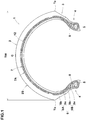
- FIG. 1 is a cross-sectional view of a motorcycle tyre (hereinafter, simply referred to as "tyre") 1 according to an embodiment of the disclosure.
- the tyre 1 according to the present embodiment may suitably be used for a road race. Note that the present disclosure is not limited to the above aspect.
- the tyre 1 includes a tread portion 2, and a pair of bead portions 4 each with a bead core 5 therein.
- the tread portion 2 has a tread surface 2S extending between tread edges Te through the tyre equator C so as to protrude radially outwardly in an arc shape manner.
- the tread width TW which is a distance in the tyre axial direction between the tread edges Te corresponds to the tyre maximum width.
- the tyre 1 is capable of cornering with large bank angles.
- the tyre 1 includes a toroidal carcass 6 extending between the pair of bead portions 4, and a band layer 7 disposed outward in a tyre radial direction of the carcass and inside the tread portion 2.
- the carcass 6 includes at least one carcass ply.
- the carcass 6 includes two carcass plies that includes an inner carcass ply 6A, and an outer carcass ply 6B disposed radially outwardly of the inner carcass ply 6A at the location of the tyre equator C.
- Each of the inner carcass ply 6A and the outer carcass ply 6B includes a main portion 6a extending between the bead cores 5 of the bead portions 4 through the tread portion 2 and sidewall portions 3, and a pair of turn-up portion 6b each turned up around a respective one of the bead cores 5.
- a bead apex rubber 8 that extends radially outwardly from a respective one of the bead cores 5 is disposed between the main portion 6a and a respective one of the turn-up portions 6b.
- the inner carcass ply 6A and the outer carcass ply 6B include carcass cords (not illustrated).
- the carcass cords are oriented at an angle of 60 to 90 degrees with respect to the tyre circumferential direction, for example.
- an organic fiber cord such as nylon, polyester, rayon and the like may preferably be employed, for example.
- the band layer 7 includes at least one band ply 7A, and in the present embodiment, one band ply 7A is employed.
- the band ply 7A has one or more steel cords 12 spirally wound in the tyre circumferential direction.
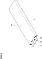
- FIG. 2 is a partial perspective view of one example of a ribbon ply 11.
- the band ply 7A according to the present embodiment is formed by arranging the ribbon ply 11 shown in FIG. 2 (e.g., by winding the ribbon ply 11 spirally) in the tyre circumferential direction.
- the ribbon ply 11 is configured to include one or more steel cords 12 (a plurality of steel cords 12 in the present example) and a topping rubber 13 coating the steel cords 12.
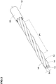
- FIG. 3 is a partial perspective view of one of the steel cords according to an embodiment.
- each steel cord 12 includes a plurality of twisted filaments 14.
- FIG. 3 illustrates a single-twisted cord with a 1x4 structure in which four filaments 14 are twisted together.
- the steel cords 12 are not limited to such an aspect.
- a single-twisted cord with a 1x5 structure, and a double twisted cord with a 3x3 structure may be adopted.
- the filaments 14 one or more pre-molded filaments (not illustrated) that are given a predetermined shape at a state before twisting, as in Patent Document 1, may be employed.
- the plurality of twisted filaments 14 is coated with rubber 15.
- the rubber 15 is filled between the filaments 14.
- the rubber 15 according to the present embodiment has the same composition as the topping rubber 13 of the band ply 7A shown in FIG. 2 .
- the tubber 15 is not limited to such an aspect.
- the rubber 15 can prevent the filaments 14 of the steel cord 12 from contacting directly with one another so that damages due to contacting of the filaments 14 with one another is prevented.
- the tyre 1 has a parameter (A) in which a load index LI (kg) of the tyre 1 is divided by a bending/compression stiffness ratio that is obtained by dividing a bending stiffness (g ⁇ cm) of the steel cords by a compression stiffness (N/mm) of the steel cords 12 being in a range of 1500 to 6000.
- the load index LI is an index which indicates the maximum mass (maximum load capacity) that can be supported by a single tyre 1 (shown in FIG. 1 ).
- the maximum load capacity (kg) corresponding to the Load Index LI of the tyre 1 is specified based on the "Table of correspondence between air pressure and load capacity" defined by the standard organization on which the tyre 1 is based.
- the bending stiffness (g/cm) is a bending stiffness of a single steel cord 12.
- the compressive stiffness (N/mm) is a compressive stiffness of a single steel cord 12.
- the bending stiffness and the compressive stiffness of the steel cord 12 are measured according to the procedure for measuring the compressive stiffness and the bending stiffness of the band cord as described in the above-mentioned Patent document 1.
- the compressive stiffness and the bending stiffness of the steel cord 12 can be adjusted as described in Patent Document 1.
- the compressive stiffness and the bending stiffness of the steel cord 12 may be adjusted by changing a twisting pitch P1 of the steel cord 12, the number of filaments 14, the outer diameter D1 of the filaments 14, and the number of pre-molded filaments (not illustrated).
- the bending/compression stiffness ratio specifies the relationship between the bending stiffness (g ⁇ cm) and the compressive stiffness (N/mm) of the steel cords 12.
- the parameter (A) which indicates the relationship between the bending/compression stiffness ratio and the load index (kg), is limited to 1500 to 6000, so that the binding/compression stiffness ratio is set in a certain range in relation to the load index (maximum load capacity).
- the bending/compression stiffness ratio with respect to the load index is greater than that of the conventional steel cords.
- such steel cords 12 receive compressive force (magnitude thereof is related to the magnitude of the load index (maximum load capacity)) at the tread contact region, they may buckle easily at or immediately the start of braking.
- the steel cords 12 located in the tread contact region can deform in a wavy manner. Such a wave-like deformation can make an area of the tread contact region linearly change and can stabilize braking force compared to that without the wave-like deformation.
- the tyre 1 according to the present embodiment (shown in FIG. 1 ) can generate wave-like deformation of the steel cord 12 located in the tread contact region from or immediately after the start of braking.
- the tyre 1 can suppress a rapid change in area of the tread contact region from the start of braking to the end.
- the tyre 1 according to the present embodiment can gradually increase braking force from the start to the end of braking of a motorcycle so as to be proportional to deceleration of the vehicle (acceleration opposite to the traveling direction). Therefore, the tyre 1 according to the present embodiment can provide a stable braking force during braking.
- the tyre 1 according to the present embodiment (shown in FIG. 1 ) is capable of causing a wave-like deformation to the steel cords 12, which are located in the tread contact region, when a motorcycle starts to turn or immediately afterwards.
- the tyre 1 according to the present embodiment can gradually increase cornering force in proportion to the load on the tyre 1 during cornering, and thus handling stability can be improved.
- the bending/compression stiffness ratio of the steel cord 12 can be increased relatively by setting the parameter (A) to less than 6000.
- the tyre 1 shown in FIG. 1
- the tyre 1 according to the present embodiment can deform the steel cords 12, which are located in the tread contact region, in a wave-like manner from the start of braking or immediately afterwards.
- the tyre 1 according to the present embodiment can prevent a rapid change in area of the tread contact region in the middle of braking.
- the bending stiffness of the steel cords 12 can be prevented from being higher than necessary by setting the parameter (A) to more than 1500.
- the compression input to the steel cords 12 can be converted to bent the steel cords 12 when the vehicle is braking.
- the tyre 1 according to the present embodiment can deform the steel cords 12 to a wavy-like manner at or immediately after the start of braking. This can prevent a rapid change in area of the tread contact region in the middle of braking.
- the steel cords 12 are prevented from increasing its bending stiffness.
- the steel cords 12 can be positioned along the outer surface of the outer carcass ply 6B (shown in FIG. 1 ), which is curved in a convex arc. This can improve the formability of the band ply 7A, and thus it can prevent the steel cords 12 (in particular, the winding end of the steel cords 12) from being lifted out in the tyre radial direction.
- the parameter (A) is preferably equal to or less than 5000, more preferably equal to or less than 4500, but preferably equal to or more than 2500, more preferably equal to or more than 3000.
- the bending stiffness of the steel cords 12 is in a range of 16 to 50 (g ⁇ cm).
- the bending stiffness equal to or less than 50 (g ⁇ cm)
- compression input to the steel cords 12 acting when a motorcycle is braking is converted into bending deformation of the steel cords 12.
- the tyre 1 according to the present embodiment (shown in FIG. 1 ) can deform the steel cords 12 to a wavy-like manner at or immediately after the start of braking.
- the steel cords 12 are flexible and bent easily, which increases resistance to bending fatigue (durability of the steel cords 12).
- the bending stiffness is set to 16 (g-cm) or more, which can prevent wavy-deformation of the steel cords 12 from becoming larger than necessary.
- the tyre 1 according to the present embodiment (shown in FIG. 1 ) can maintain rigidity of the tread contact surface, and thus braking and handling stability may be improved.
- the bending stiffness is preferably equal to or less than 40 (g ⁇ cm), and preferably equal to or more than 25 (g ⁇ cm).
- the compression stiffness of the steel cords 12 is in a range of 150 to 350 (N/mm).
- the compression stiffness is set equal to or less than 350 (N/mm)
- a wavy-like deformation of the steel cords 12 in the tread ground region of the tyre 1 can occur at the start of braking or immediately afterwards.
- the compression input to the steel cords 12 can be converted into its wavy bending deformation.
- the tyre 1 according to the present embodiment can increase compression fatigue resistance (durability) of the steel cords 12.
- the compression stiffness is preferably equal to or less than 300 (N/mm), and preferably equal to or more than 200 (N/mm).
- the rubber 15 is filled between the filaments 14.
- Such rubber 15 is capable of absorbing part of the force acting on the filaments 14 of the steel cords 12, which are located in the tread contact region when a motorcycle is braking.
- the tyre 1 according to the present embodiment shown in FIG. 1 ) can prevent the steel cords 12 from waving more than necessary, and thus improving braking and handling stability.
- a parameter (B) of each steel cord 12 in which the number of filaments 14 of each steel cord 12 is divided by a twisting pitch (mm) of a respective one of the steel cords 12 is less than 1.5 (threads/mm).
- the steel cords 12 can prevent the steel cords 12 from increasing in outer diameter as well as from decreasing in compression stiffness more than necessary, even when the steel cords 12 are subjected to compression force during braking. Therefore, the tyre 1 of the present embodiment (shown in FIG. 1 ) can maintain stiffness of the tread contact region, improving braking and handling stability.
- the parameter (B) is preferably less than 1.0 (threads/mm).
- the parameter (B) is set equal to or more than 0.3 (threads/mm). This can prevent the compression stiffness of the steel cords 12 from being greater than necessary.
- the tyre 1 shown in FIG. 1 ) according to the present embodiment can cause wavy-deformation of the steel cord 12 at the start of braking or immediately afterwards.
- the number of the steel cords 12 in the ribbon ply 11 shown in FIG. 2 is equal to or less than 5. This can prevent the tyre 1 according to the present embodiment (shown in FIG. 1 ) from having a large difference in the winding diameter of each steel cord 12 in the ribbon ply 11 due to the curvature of the outer carcass ply 6B. Thus, the tyre 1 can have a nearly uniform distribution of stiffness in the tyre axial direction of the band ply 7A, improving braking and handling stability.
- the number of the steel cords 12 in the ribbon ply 11 is preferably 4 or less, and more preferably 3 or less.
- the number of the steel cords 12 in the ribbon ply 11 is equal to or more than two. This can prevent the increase in the number of winding of the ribbon ply 11 in the manufacturing process of the tyre 1 (shown in FIG. 1 ) and thus prevents the increase in the manufacturing cost.
- Tyres having the basic structure of FIG. 1 have been prototyped based on specifications in Tables 1 to 3 (Examples 1 to 23, and references 1 to 5). These tyres were evaluated for braking stability and formability of the band ply.
- the common specification of each tyre is as follows.
- the test method is as follows.
- each test tyre is mounted on the front wheel of the above motorcycle. Then, a test rider rode the test vehicle on a dry asphalt test course to evaluate the braking stability by the rider's sensory using a 10-point method.
- the test results are shown in Tables 1 to 3. The higher value indicates the better the braking stability, meaning that braking force increases in proportion to the deceleration of the motorcycle during the braking.
- the ribbon ply shown in FIG. 2 was wound around the tyre circumferential direction to form the band ply of each test tyre. After the winding of the ribbon ply was completed, the ends of steel cords were visually checked whether or not it floated outwardly in the tyre radial direction. The test results are shown in Tables 1 to 3 by "OK" when the steel cords did not float and "NG" when it floated.
- the example tyres have improved braking stability compared to the comparative example tyres, while maintaining the formability of band ply.
- a motorcycle tyre includes a tread portion, a pair of bead portions, a toroidal carcass extending between the pair of bead portions, and a band layer disposed outward in a tyre radial direction of the carcass and inside the tread portion.
- the band layer includes a band ply having one or more steel cords spirally wound in a tyre circumferential direction.
- the tyre has a parameter (A) in which a load index LI (kg) of the tyre is divided by a bending/compression stiffness ratio that is obtained by dividing a bending stiffness (g ⁇ cm) of the steel cords by a compression stiffness (N/mm) of the steel cords being in a range of 1500 to 6000.
Landscapes
- Engineering & Computer Science (AREA)
- Mechanical Engineering (AREA)
- Tires In General (AREA)
Abstract
Description
- The present disclosure relates to a motorcycle tyre.
- The following Patent document 1 discloses a motorcycle tyre including a carcass and a band layer disposed radially outwardly of the carcass. The band layer includes a band ply including one or more steel band cords wound spirally in the tyre circumferential direction. In the tyre, compressive stiffness and bending stiffness of the band cords are limited to a certain range to improve handling stability.
- [Patent document 1] Japanese Unexamined Patent Application Publication
2018-167716 - Generally, it has been required that braking force should increase gradually in proportion to the deceleration (the acceleration opposite to the direction of travel) of a motorcycle from the start of braking to the end. However, depending on tyres, there was a case in which braking force increased rapidly during a period from the start of braking to the end. Thus, improving stability during braking (hereinafter referred to as "braking stability") has been required. In particular, for tyres used under severe conditions, such as racing tyres, superior braking stability is required as it has a significant impact on lap times.
- The inventors have studied rapid changes in braking force as described above. As a result, it has been found that when compressive rigidity of the band cords is relatively high, some of the band cords located in the tread contact region bend suddenly in the tyre radial direction of the tread contact region in the middle of braking in a waving manner. Then, it is assumed that waving of the band cords in the middle of braking causes rapid increase or decrease an area of the tread contact region, leading to rapid changes in braking force.
- The present disclosure has been made in view of the above circumstances and has a major object to provide a motorcycle tyre capable of improving braking stability.
- In one aspect of the disclosure, a motorcycle tyre includes a tread portion, a pair of bead portions, a toroidal carcass extending between the pair of bead portions, and a band layer disposed outward in a tyre radial direction of the carcass and inside the tread portion, the band layer including a band ply having one or more steel cords spirally wound in a tyre circumferential direction, wherein the tyre has a parameter (A) in which a load index LI (kg) of the tyre is divided by a bending/compression stiffness ratio that is obtained by dividing a bending stiffness (g·cm) of the steel cords by a compression stiffness (N/mm) of the steel cords being in a range of 1500 to 6000.
- In another aspect of the disclosure, the bending stiffness of the steel cords may be in a range of 16 to 50 (g·cm).
- In another aspect of the disclosure, the steel cords may include a plurality of twisted filaments and rubber filled between the plurality of filaments.
- In another aspect of the disclosure, a parameter (B) of the steel cords in which a number of filaments of each steel cord is divided by a twisting pitch (mm) of a respective one of the steel cords may be less than 1.5 (threads/mm).
- In another aspect of the disclosure, the band ply may be formed by winding a ribbon ply spirally in the tyre circumferential direction, and the ribbon ply may include five or less of the steel cords and a topping rubber coating the steel cords.
- In another aspect of the disclosure, the parameter (A) may be in a range of 2500 to 5000.
- In another aspect of the disclosure, the parameter (A) may be in a range of 3000 to 4500.
-
-
FIG. 1 is a cross-sectional view of a motorcycle tyre according to an embodiment of the disclosure; -
FIG. 2 is a partial perspective view of a ribbon ply according to an embodiment, and -
FIG. 3 is a partial perspective view of a steel cord according to an embodiment. - An embodiment of the present disclosure will be explained below with reference to the accompanying drawings.
-
FIG. 1 is a cross-sectional view of a motorcycle tyre (hereinafter, simply referred to as "tyre") 1 according to an embodiment of the disclosure. The tyre 1 according to the present embodiment, for example, may suitably be used for a road race. Note that the present disclosure is not limited to the above aspect. - The tyre 1 includes a
tread portion 2, and a pair ofbead portions 4 each with abead core 5 therein. In the present embodiment, thetread portion 2 has atread surface 2S extending between tread edges Te through the tyre equator C so as to protrude radially outwardly in an arc shape manner. The tread width TW which is a distance in the tyre axial direction between the tread edges Te corresponds to the tyre maximum width. Thus, the tyre 1 is capable of cornering with large bank angles. - The tyre 1 according to the present embodiment includes a toroidal carcass 6 extending between the pair of
bead portions 4, and aband layer 7 disposed outward in a tyre radial direction of the carcass and inside thetread portion 2. - The carcass 6 includes at least one carcass ply. In the present embodiment, the carcass 6 includes two carcass plies that includes an
inner carcass ply 6A, and anouter carcass ply 6B disposed radially outwardly of theinner carcass ply 6A at the location of the tyre equator C. Each of theinner carcass ply 6A and theouter carcass ply 6B includes amain portion 6a extending between thebead cores 5 of thebead portions 4 through thetread portion 2 and sidewall portions 3, and a pair of turn-upportion 6b each turned up around a respective one of thebead cores 5. Abead apex rubber 8 that extends radially outwardly from a respective one of thebead cores 5 is disposed between themain portion 6a and a respective one of the turn-upportions 6b. - The
inner carcass ply 6A and theouter carcass ply 6B include carcass cords (not illustrated). The carcass cords are oriented at an angle of 60 to 90 degrees with respect to the tyre circumferential direction, for example. As the carcass cords, an organic fiber cord, such as nylon, polyester, rayon and the like may preferably be employed, for example. - The
band layer 7 includes at least oneband ply 7A, and in the present embodiment, oneband ply 7A is employed. Theband ply 7A has one ormore steel cords 12 spirally wound in the tyre circumferential direction.FIG. 2 is a partial perspective view of one example of aribbon ply 11. - The
band ply 7A according to the present embodiment (shown inFIG. 1 ) is formed by arranging theribbon ply 11 shown inFIG. 2 (e.g., by winding theribbon ply 11 spirally) in the tyre circumferential direction. Theribbon ply 11 is configured to include one or more steel cords 12 (a plurality ofsteel cords 12 in the present example) and a toppingrubber 13 coating thesteel cords 12. -
FIG. 3 is a partial perspective view of one of the steel cords according to an embodiment. In the present embodiment, eachsteel cord 12 includes a plurality oftwisted filaments 14. As asteel cord 12,FIG. 3 illustrates a single-twisted cord with a 1x4 structure in which fourfilaments 14 are twisted together. Note that thesteel cords 12 are not limited to such an aspect. As thesteel cords 12, for example, a single-twisted cord with a 1x5 structure, and a double twisted cord with a 3x3 structure may be adopted. Further, as thefilaments 14, one or more pre-molded filaments (not illustrated) that are given a predetermined shape at a state before twisting, as in Patent Document 1, may be employed. - In the present embodiment, the plurality of
twisted filaments 14 is coated withrubber 15. Thus, in the present embodiment, therubber 15 is filled between thefilaments 14. Therubber 15 according to the present embodiment has the same composition as thetopping rubber 13 of theband ply 7A shown inFIG. 2 . Note that thetubber 15 is not limited to such an aspect. Therubber 15 can prevent thefilaments 14 of thesteel cord 12 from contacting directly with one another so that damages due to contacting of thefilaments 14 with one another is prevented. - In the present embodiment, the tyre 1 has a parameter (A) in which a load index LI (kg) of the tyre 1 is divided by a bending/compression stiffness ratio that is obtained by dividing a bending stiffness (g·cm) of the steel cords by a compression stiffness (N/mm) of the
steel cords 12 being in a range of 1500 to 6000. - The load index LI is an index which indicates the maximum mass (maximum load capacity) that can be supported by a single tyre 1 (shown in
FIG. 1 ). In the present embodiment, the maximum load capacity (kg) corresponding to the Load Index LI of the tyre 1 is specified based on the "Table of correspondence between air pressure and load capacity" defined by the standard organization on which the tyre 1 is based. - The bending stiffness (g/cm) is a bending stiffness of a
single steel cord 12. The compressive stiffness (N/mm) is a compressive stiffness of asingle steel cord 12. In the present embodiment, the bending stiffness and the compressive stiffness of thesteel cord 12 are measured according to the procedure for measuring the compressive stiffness and the bending stiffness of the band cord as described in the above-mentioned Patent document 1. - The compressive stiffness and the bending stiffness of the
steel cord 12 can be adjusted as described in Patent Document 1. In this embodiment, the compressive stiffness and the bending stiffness of thesteel cord 12, for example, may be adjusted by changing a twisting pitch P1 of thesteel cord 12, the number offilaments 14, the outer diameter D1 of thefilaments 14, and the number of pre-molded filaments (not illustrated). - The bending/compression stiffness ratio specifies the relationship between the bending stiffness (g·cm) and the compressive stiffness (N/mm) of the
steel cords 12. The parameter (A), which indicates the relationship between the bending/compression stiffness ratio and the load index (kg), is limited to 1500 to 6000, so that the binding/compression stiffness ratio is set in a certain range in relation to the load index (maximum load capacity). - In the present embodiment, by setting the parameter (A) into the above range, the bending/compression stiffness ratio with respect to the load index is greater than that of the conventional steel cords. When braking a motorcycle,
such steel cords 12 receive compressive force (magnitude thereof is related to the magnitude of the load index (maximum load capacity)) at the tread contact region, they may buckle easily at or immediately the start of braking. In the present embodiment, thesteel cords 12 located in the tread contact region can deform in a wavy manner. Such a wave-like deformation can make an area of the tread contact region linearly change and can stabilize braking force compared to that without the wave-like deformation. - The tyre 1 according to the present embodiment (shown in
FIG. 1 ) can generate wave-like deformation of thesteel cord 12 located in the tread contact region from or immediately after the start of braking. Thus, the tyre 1 can suppress a rapid change in area of the tread contact region from the start of braking to the end. As a result, the tyre 1 according to the present embodiment can gradually increase braking force from the start to the end of braking of a motorcycle so as to be proportional to deceleration of the vehicle (acceleration opposite to the traveling direction). Therefore, the tyre 1 according to the present embodiment can provide a stable braking force during braking. - Furthermore, the tyre 1 according to the present embodiment (shown in
FIG. 1 ) is capable of causing a wave-like deformation to thesteel cords 12, which are located in the tread contact region, when a motorcycle starts to turn or immediately afterwards. Thus, the tyre 1 according to the present embodiment can gradually increase cornering force in proportion to the load on the tyre 1 during cornering, and thus handling stability can be improved. - In the present embodiment, the bending/compression stiffness ratio of the
steel cord 12 can be increased relatively by setting the parameter (A) to less than 6000. As a result, the tyre 1 (shown inFIG. 1 ) according to the present embodiment can deform thesteel cords 12, which are located in the tread contact region, in a wave-like manner from the start of braking or immediately afterwards. Thus, the tyre 1 according to the present embodiment can prevent a rapid change in area of the tread contact region in the middle of braking. - On the other hand, in the present embodiment, the bending stiffness of the
steel cords 12 can be prevented from being higher than necessary by setting the parameter (A) to more than 1500. Thus, in the tyre 1 according to the present embodiment (shown inFIG. 1 ), the compression input to thesteel cords 12 can be converted to bent thesteel cords 12 when the vehicle is braking. Thus, the tyre 1 according to the present embodiment (shown inFIG. 1 ) can deform thesteel cords 12 to a wavy-like manner at or immediately after the start of braking. This can prevent a rapid change in area of the tread contact region in the middle of braking. In addition, thesteel cords 12 are prevented from increasing its bending stiffness. Thus, in a forming process of theband ply 7A in which the ribbon ply 11 (shown inFIG. 2 ) is wound, thesteel cords 12 can be positioned along the outer surface of the outer carcass ply 6B (shown inFIG. 1 ), which is curved in a convex arc. This can improve the formability of theband ply 7A, and thus it can prevent the steel cords 12 (in particular, the winding end of the steel cords 12) from being lifted out in the tyre radial direction. - In order to further improve the effect as mentioned above, the parameter (A) is preferably equal to or less than 5000, more preferably equal to or less than 4500, but preferably equal to or more than 2500, more preferably equal to or more than 3000.
- Preferably, the bending stiffness of the
steel cords 12 is in a range of 16 to 50 (g·cm). In the present embodiment, by setting the bending stiffness equal to or less than 50 (g·cm), compression input to thesteel cords 12 acting when a motorcycle is braking is converted into bending deformation of thesteel cords 12. Thus, the tyre 1 according to the present embodiment (shown inFIG. 1 ) can deform thesteel cords 12 to a wavy-like manner at or immediately after the start of braking. Further, by setting the bending stiffness equal to or less than 50 (g·cm), thesteel cords 12 are flexible and bent easily, which increases resistance to bending fatigue (durability of the steel cords 12). - On the other hand, in the present embodiment, the bending stiffness is set to 16 (g-cm) or more, which can prevent wavy-deformation of the
steel cords 12 from becoming larger than necessary. As a result, the tyre 1 according to the present embodiment (shown inFIG. 1 ) can maintain rigidity of the tread contact surface, and thus braking and handling stability may be improved. In order to further improve the effect as mentioned above, the bending stiffness is preferably equal to or less than 40 (g·cm), and preferably equal to or more than 25 (g·cm). - Preferably, the compression stiffness of the
steel cords 12 is in a range of 150 to 350 (N/mm). By setting the compression stiffness equal to or less than 350 (N/mm), a wavy-like deformation of thesteel cords 12 in the tread ground region of the tyre 1 can occur at the start of braking or immediately afterwards. Further, by setting the compression stiffness equal to or less than 350 (N/mm), the compression input to thesteel cords 12 can be converted into its wavy bending deformation. As a result, the tyre 1 according to the present embodiment can increase compression fatigue resistance (durability) of thesteel cords 12. - On the other hand, by setting the compression stiffness equal to or more than 150 (N/mm), wavy-like deformation of the
steel cords 12 is prevented from becoming larger than necessary. In order to further improve the effect as mentioned above, the compression stiffness is preferably equal to or less than 300 (N/mm), and preferably equal to or more than 200 (N/mm). - In the
steel cords 12 according to the present embodiment, therubber 15 is filled between thefilaments 14.Such rubber 15 is capable of absorbing part of the force acting on thefilaments 14 of thesteel cords 12, which are located in the tread contact region when a motorcycle is braking. As a result, the tyre 1 according to the present embodiment (shown inFIG. 1 ) can prevent thesteel cords 12 from waving more than necessary, and thus improving braking and handling stability. - Preferably, a parameter (B) of each
steel cord 12 in which the number offilaments 14 of eachsteel cord 12 is divided by a twisting pitch (mm) of a respective one of thesteel cords 12 is less than 1.5 (threads/mm). This can prevent thesteel cords 12 from becoming more dense than necessary. Thus, thesteel cords 12 can prevent thesteel cords 12 from increasing in outer diameter as well as from decreasing in compression stiffness more than necessary, even when thesteel cords 12 are subjected to compression force during braking. Therefore, the tyre 1 of the present embodiment (shown inFIG. 1 ) can maintain stiffness of the tread contact region, improving braking and handling stability. In order to further improve the effect as mentioned above, the parameter (B) is preferably less than 1.0 (threads/mm). - Preferably, the parameter (B) is set equal to or more than 0.3 (threads/mm). This can prevent the compression stiffness of the
steel cords 12 from being greater than necessary. Thus, the tyre 1 (shown inFIG. 1 ) according to the present embodiment can cause wavy-deformation of thesteel cord 12 at the start of braking or immediately afterwards. - Preferably, the number of the
steel cords 12 in the ribbon ply 11 shown inFIG. 2 is equal to or less than 5. This can prevent the tyre 1 according to the present embodiment (shown inFIG. 1 ) from having a large difference in the winding diameter of eachsteel cord 12 in the ribbon ply 11 due to the curvature of theouter carcass ply 6B. Thus, the tyre 1 can have a nearly uniform distribution of stiffness in the tyre axial direction of theband ply 7A, improving braking and handling stability. In order to further improve the effect as mentioned above, the number of thesteel cords 12 in the ribbon ply 11 is preferably 4 or less, and more preferably 3 or less. - Preferably, the number of the
steel cords 12 in the ribbon ply 11 is equal to or more than two. This can prevent the increase in the number of winding of the ribbon ply 11 in the manufacturing process of the tyre 1 (shown inFIG. 1 ) and thus prevents the increase in the manufacturing cost. - While the particularly preferable embodiments in accordance with the present disclosure have been described in detail, the present disclosure is not limited to the illustrated embodiments, but can be modified and carried out in various aspects.
- Tyres having the basic structure of
FIG. 1 have been prototyped based on specifications in Tables 1 to 3 (Examples 1 to 23, and references 1 to 5). These tyres were evaluated for braking stability and formability of the band ply. The common specification of each tyre is as follows. - Tyre size: 120/70ZR17
- Rim size: 17x3.5MT
- Load index LI (Maximum load capacity): 58 (236 kg)
- Tyre mounting position: Front wheel
- Tyre pressure: 250 kPa
- Motorcycle: two-wheeled motorcycles of 1000 cc displacement
- The test method is as follows.
- Under the above conditions, each test tyre is mounted on the front wheel of the above motorcycle. Then, a test rider rode the test vehicle on a dry asphalt test course to evaluate the braking stability by the rider's sensory using a 10-point method. The test results are shown in Tables 1 to 3. The higher value indicates the better the braking stability, meaning that braking force increases in proportion to the deceleration of the motorcycle during the braking.
- The ribbon ply shown in
FIG. 2 was wound around the tyre circumferential direction to form the band ply of each test tyre. After the winding of the ribbon ply was completed, the ends of steel cords were visually checked whether or not it floated outwardly in the tyre radial direction. The test results are shown in Tables 1 to 3 by "OK" when the steel cords did not float and "NG" when it floated. - Tables 1 to 3 show the test results.
[Table 1] Ref. 1 Ref. 2 Ref. 3 Ex. 1 Ex. 2 Ex. 3 Ex. 4 Ex. 5 Ref. 4 Ex. 6 Parameter (A) 1450 1250 8230 2350 5340 3430 4210 1820 1328 1549 Bending stiffness (g·cm) of steel cords 16 42 11 16 80 43 32 25 16 16 Compression stiffness of steel cords (N/mm) 98.3 222.5 383.6 159.3 1810.2 625.0 570.8 192.8 90.0 105.0 Bending/compression stiffness ratio 0.163 0.189 0.029 0.1 0.044 0.069 0.056 0.13 0.178 0.152 Number of steel cord in ribbon ply 3 3 3 3 3 5 3 3 3 3 Number of filaments in steel cord 9 4 4 4 4 5 9 9 4 4 Twisting pitch (mm) 6.0 12.0 6.0 12.0 6.0 12.0 6.0 6.0 12.0 12.0 Parameter (B) 1.50 0.33 0.67 0.33 0.67 0.42 1.50 1.50 0.33 0.33 Rubber between filaments presence presence presence presence presence presence presence presence presence presence Braking stability (10-point method) 6.7 7 4 8.2 8.3 6.8 8.1 8.1 6.9 8.1 Formability of band ply NG NG OK OK OK OK OK OK NG OK [Table 2] Ex. 7 Ex. 8 Ex. 9 Ex. 10 Ex. 11 Ref. 5 Ex. 12 Ex. 13 Ex. 14 Ex. 15 Parameter (A) 2500 3000 4500 5000 6000 6195 5715 3200 2667 2000 Bending stiffness (g·cm) of steel cords 16 16 16 16 16 16 14 25 30 40 Compression stiffness of steel cords (N/mm) 169.5 203.4 305.1 339.0 406.8 420.0 339.0 339.0 339.0 339.0 Bending/compression stiffness ratio 0.094 0.079 0.052 0.047 0.039 0.038 0.041 0.074 0.088 0.118 Number of steel cord in ribbon ply 3 3 3 3 3 3 3 3 3 3 Number of filaments in steel cord 4 4 4 4 4 4 4 4 4 4 Twisting pitch (mm) 12.0 12.0 12.0 12.0 12.0 12.0 12.0 12.0 12.0 12.0 Parameter (B) 0.33 0.33 0.33 0.33 0.33 0.33 0.33 0.33 0.33 0.33 Rubber between filaments presence presence presence presence presence presence presence presence presence presence Braking stability (10-point method) 8.3 8.4 8.4 8.3 8.1 6 8 8.4 8.5 8.4 Formability of band ply OK OK OK OK OK OK OK OK OK OK [Table 3] Ex. 16 Ex. 17 Ex. 18 Ex. 19 Ex. 20 Ex. 21 Ex. 22 Ex. 23 Parameter (A) 1600 1539 5000 5000 5000 5000 5000 5000 Bending stiffness (g·cm) of steel cords 50 52 16 16 16 16 16 16 Compression stiffness of steel cords (N/mm) 339.0 339.0 339.0 339.0 339.0 339.0 339.0 339.0 Bending/compression stiffness ratio 0.147 0.153 0.047 0.047 0.047 0.047 0.047 0.047 Number of steel cord in ribbon ply 3 3 5 6 3 3 3 3 Number of filaments in steel cord 4 4 4 4 4 4 4 4 Twisting pitch (mm) 12.0 12.0 12.0 12.0 15.0 2.7 2.4 2.4 Parameter (B) 0.33 0.33 0.33 0.33 0.27 1.48 1.67 1.67 Rubber between filaments presence presence presence presence presence presence presence none Braking stability (10-point method) 8.3 8 8.1 7.9 8.0 8.2 7.9 8.1 Formability of band ply OK OK OK OK OK OK OK OK - As a result of the tests, the example tyres have improved braking stability compared to the comparative example tyres, while maintaining the formability of band ply.
- A motorcycle tyre includes a tread portion, a pair of bead portions, a toroidal carcass extending between the pair of bead portions, and a band layer disposed outward in a tyre radial direction of the carcass and inside the tread portion. The band layer includes a band ply having one or more steel cords spirally wound in a tyre circumferential direction. The tyre has a parameter (A) in which a load index LI (kg) of the tyre is divided by a bending/compression stiffness ratio that is obtained by dividing a bending stiffness (g·cm) of the steel cords by a compression stiffness (N/mm) of the steel cords being in a range of 1500 to 6000.
Claims (7)
- A motorcycle tyre comprising:a tread portion;a pair of bead portions;a toroidal carcass extending between the pair of bead portions; anda band layer disposed outward in a tyre radial direction of the carcass and inside the tread portion, the band layer comprising a band ply having one or more steel cords spirally wound in a tyre circumferential direction, whereinthe tyre has a parameter (A) in which a load index LI (kg) of the tyre is divided by a bending/compression stiffness ratio that is obtained by dividing a bending stiffness (g·cm) of the steel cords by a compression stiffness (N/mm) of the steel cords being in a range of 1500 to 6000.
- The motorcycle tyre according to claim 1, wherein
the bending stiffness of the steel cords is in a range of 16 to 50 (g·cm). - The motorcycle tyre according to claim 1 or 2, wherein
the steel cords comprise a plurality of twisted filaments and rubber filled between the plurality of filaments. - The motorcycle tyre according to claim 3, wherein
a parameter B of the steel cords in which a number of filaments of each steel cord is divided by a twisting pitch (mm) of a respective one of the steel cords is less than 1.5 (threads/mm). - The motorcycle tyre according to any one of claims 1 to 4, wherein
the band ply is formed by winding a ribbon ply spirally in the tyre circumferential direction, and
the ribbon ply comprises five or less of the steel cords and a topping rubber coating the steel cords. - The motorcycle tyre according to any one of claims 1 to 5, wherein
the parameter (A) is in a range of 2500 to 5000. - The motorcycle tyre according to any one of claims 1 to 6, wherein
the parameter (A) is in a range of 3000 to 4500.
Applications Claiming Priority (1)
| Application Number | Priority Date | Filing Date | Title |
|---|---|---|---|
| JP2019236948A JP7375534B2 (en) | 2019-12-26 | 2019-12-26 | motorcycle tires |
Publications (2)
| Publication Number | Publication Date |
|---|---|
| EP3842260A1 true EP3842260A1 (en) | 2021-06-30 |
| EP3842260B1 EP3842260B1 (en) | 2023-08-09 |
Family
ID=73598707
Family Applications (1)
| Application Number | Title | Priority Date | Filing Date |
|---|---|---|---|
| EP20209963.6A Active EP3842260B1 (en) | 2019-12-26 | 2020-11-26 | Motorcycle tyre |
Country Status (4)
| Country | Link |
|---|---|
| US (1) | US11535059B2 (en) |
| EP (1) | EP3842260B1 (en) |
| JP (1) | JP7375534B2 (en) |
| CN (1) | CN113043792B (en) |
Families Citing this family (3)
| Publication number | Priority date | Publication date | Assignee | Title |
|---|---|---|---|---|
| JP7329381B2 (en) * | 2019-07-22 | 2023-08-18 | 株式会社ブリヂストン | Control method, control device, control system and tire test method |
| JP2024089175A (en) * | 2022-12-21 | 2024-07-03 | 株式会社ブリヂストン | Motorcycle tires |
| JP2024089176A (en) * | 2022-12-21 | 2024-07-03 | 株式会社ブリヂストン | Motorcycle tires |
Citations (3)
| Publication number | Priority date | Publication date | Assignee | Title |
|---|---|---|---|---|
| EP1983098A1 (en) * | 2006-01-20 | 2008-10-22 | Bridgestone Corporation | Rubber-steel cord composite and tire using the same |
| US20130168003A1 (en) * | 2011-12-28 | 2013-07-04 | Sumitomo Rubber Industries, Ltd. | Pneumatic tire |
| EP3381714A1 (en) * | 2017-03-30 | 2018-10-03 | Sumitomo Rubber Industries, Ltd. | Motorcycle tire |
Family Cites Families (7)
| Publication number | Priority date | Publication date | Assignee | Title |
|---|---|---|---|---|
| JP4478381B2 (en) * | 2002-11-08 | 2010-06-09 | 不二精工株式会社 | Radial tire with crossed body ply cord |
| JP3947137B2 (en) * | 2003-06-12 | 2007-07-18 | 住友ゴム工業株式会社 | Radial tires for motorcycles |
| JP5069517B2 (en) * | 2007-08-10 | 2012-11-07 | 住友ゴム工業株式会社 | Belt-like ply and pneumatic tire using the same |
| JP5432980B2 (en) * | 2011-12-22 | 2014-03-05 | 住友ゴム工業株式会社 | Pneumatic tire |
| WO2013098735A1 (en) * | 2011-12-27 | 2013-07-04 | Pirelli Tyre S.P.A. | Tyre for motorcycles |
| JP6058294B2 (en) * | 2012-06-18 | 2017-01-11 | 住友ゴム工業株式会社 | Pneumatic tires for motorcycles |
| JP2014172547A (en) * | 2013-03-11 | 2014-09-22 | Sumitomo Rubber Ind Ltd | Radial tire for motorcycle |
-
2019
- 2019-12-26 JP JP2019236948A patent/JP7375534B2/en active Active
-
2020
- 2020-11-19 CN CN202011300328.7A patent/CN113043792B/en active Active
- 2020-11-26 EP EP20209963.6A patent/EP3842260B1/en active Active
- 2020-12-04 US US17/112,312 patent/US11535059B2/en active Active
Patent Citations (4)
| Publication number | Priority date | Publication date | Assignee | Title |
|---|---|---|---|---|
| EP1983098A1 (en) * | 2006-01-20 | 2008-10-22 | Bridgestone Corporation | Rubber-steel cord composite and tire using the same |
| US20130168003A1 (en) * | 2011-12-28 | 2013-07-04 | Sumitomo Rubber Industries, Ltd. | Pneumatic tire |
| EP3381714A1 (en) * | 2017-03-30 | 2018-10-03 | Sumitomo Rubber Industries, Ltd. | Motorcycle tire |
| JP2018167716A (en) | 2017-03-30 | 2018-11-01 | 住友ゴム工業株式会社 | Tire for motorcycle |
Also Published As
| Publication number | Publication date |
|---|---|
| EP3842260B1 (en) | 2023-08-09 |
| CN113043792A (en) | 2021-06-29 |
| CN113043792B (en) | 2023-10-31 |
| JP7375534B2 (en) | 2023-11-08 |
| US20210197619A1 (en) | 2021-07-01 |
| US11535059B2 (en) | 2022-12-27 |
| JP2021104743A (en) | 2021-07-26 |
Similar Documents
| Publication | Publication Date | Title |
|---|---|---|
| EP3842260A1 (en) | Motorcycle tyre | |
| JP4814979B2 (en) | Tire cord and pneumatic tire using the same | |
| EP3530485B2 (en) | Pneumatic tire | |
| WO2016067513A1 (en) | Pneumatic tire for passenger cars | |
| US5419383A (en) | Pneumatic tire including hybrid belt cord | |
| US11104185B2 (en) | Method of manufacturing motorcycle tire for uneven terrain travel | |
| JP2003237315A (en) | Pneumatic radial tire, and method for manufacturing the same | |
| EP3178666B1 (en) | Tire for two-wheeled vehicles | |
| JP2001354013A (en) | Pneumatic tire | |
| JPH04278805A (en) | Pneumatic tire for motorcycle | |
| WO2016024391A1 (en) | Pneumatic tire | |
| JPH1111113A (en) | Pneumatic tire and drum for molding this pneumatic tire | |
| JP4166308B2 (en) | Pneumatic tire | |
| US20130168003A1 (en) | Pneumatic tire | |
| EP2777948B1 (en) | Radial tire for motorcycle | |
| JPH0478602A (en) | Pneumatic tire | |
| JP4424832B2 (en) | Pneumatic radial tire for motorcycles | |
| JP3372347B2 (en) | Pneumatic radial tire | |
| JP5030545B2 (en) | Pneumatic radial tire | |
| JP7188038B2 (en) | pneumatic tire | |
| JPH05604A (en) | Radial tire for motorcycle | |
| WO2024127732A1 (en) | Motorcycle tire | |
| JPH01141103A (en) | Pneumatic radial tyre | |
| EP4282668A1 (en) | Pneumatic tire | |
| WO2020122250A1 (en) | Pneumatic tyre |
Legal Events
| Date | Code | Title | Description |
|---|---|---|---|
| PUAI | Public reference made under article 153(3) epc to a published international application that has entered the european phase |
Free format text: ORIGINAL CODE: 0009012 |
|
| STAA | Information on the status of an ep patent application or granted ep patent |
Free format text: STATUS: THE APPLICATION HAS BEEN PUBLISHED |
|
| AK | Designated contracting states |
Kind code of ref document: A1 Designated state(s): AL AT BE BG CH CY CZ DE DK EE ES FI FR GB GR HR HU IE IS IT LI LT LU LV MC MK MT NL NO PL PT RO RS SE SI SK SM TR |
|
| STAA | Information on the status of an ep patent application or granted ep patent |
Free format text: STATUS: REQUEST FOR EXAMINATION WAS MADE |
|
| 17P | Request for examination filed |
Effective date: 20210712 |
|
| STAA | Information on the status of an ep patent application or granted ep patent |
Free format text: STATUS: EXAMINATION IS IN PROGRESS |
|
| 17Q | First examination report despatched |
Effective date: 20220720 |
|
| GRAP | Despatch of communication of intention to grant a patent |
Free format text: ORIGINAL CODE: EPIDOSNIGR1 |
|
| STAA | Information on the status of an ep patent application or granted ep patent |
Free format text: STATUS: GRANT OF PATENT IS INTENDED |
|
| RIC1 | Information provided on ipc code assigned before grant |
Ipc: B60C 9/18 20060101ALN20230417BHEP Ipc: B60C 9/00 20060101AFI20230417BHEP |
|
| INTG | Intention to grant announced |
Effective date: 20230516 |
|
| P01 | Opt-out of the competence of the unified patent court (upc) registered |
Effective date: 20230510 |
|
| GRAS | Grant fee paid |
Free format text: ORIGINAL CODE: EPIDOSNIGR3 |
|
| GRAA | (expected) grant |
Free format text: ORIGINAL CODE: 0009210 |
|
| STAA | Information on the status of an ep patent application or granted ep patent |
Free format text: STATUS: THE PATENT HAS BEEN GRANTED |
|
| AK | Designated contracting states |
Kind code of ref document: B1 Designated state(s): AL AT BE BG CH CY CZ DE DK EE ES FI FR GB GR HR HU IE IS IT LI LT LU LV MC MK MT NL NO PL PT RO RS SE SI SK SM TR |
|
| REG | Reference to a national code |
Ref country code: GB Ref legal event code: FG4D |
|
| REG | Reference to a national code |
Ref country code: CH Ref legal event code: EP |
|
| REG | Reference to a national code |
Ref country code: DE Ref legal event code: R096 Ref document number: 602020015340 Country of ref document: DE |
|
| REG | Reference to a national code |
Ref country code: IE Ref legal event code: FG4D |
|
| REG | Reference to a national code |
Ref country code: LT Ref legal event code: MG9D |
|
| REG | Reference to a national code |
Ref country code: NL Ref legal event code: MP Effective date: 20230809 |
|
| REG | Reference to a national code |
Ref country code: AT Ref legal event code: MK05 Ref document number: 1597086 Country of ref document: AT Kind code of ref document: T Effective date: 20230809 |
|
| PG25 | Lapsed in a contracting state [announced via postgrant information from national office to epo] |
Ref country code: GR Free format text: LAPSE BECAUSE OF FAILURE TO SUBMIT A TRANSLATION OF THE DESCRIPTION OR TO PAY THE FEE WITHIN THE PRESCRIBED TIME-LIMIT Effective date: 20231110 |
|
| PG25 | Lapsed in a contracting state [announced via postgrant information from national office to epo] |
Ref country code: IS Free format text: LAPSE BECAUSE OF FAILURE TO SUBMIT A TRANSLATION OF THE DESCRIPTION OR TO PAY THE FEE WITHIN THE PRESCRIBED TIME-LIMIT Effective date: 20231209 |
|
| PG25 | Lapsed in a contracting state [announced via postgrant information from national office to epo] |
Ref country code: SE Free format text: LAPSE BECAUSE OF FAILURE TO SUBMIT A TRANSLATION OF THE DESCRIPTION OR TO PAY THE FEE WITHIN THE PRESCRIBED TIME-LIMIT Effective date: 20230809 Ref country code: RS Free format text: LAPSE BECAUSE OF FAILURE TO SUBMIT A TRANSLATION OF THE DESCRIPTION OR TO PAY THE FEE WITHIN THE PRESCRIBED TIME-LIMIT Effective date: 20230809 Ref country code: PT Free format text: LAPSE BECAUSE OF FAILURE TO SUBMIT A TRANSLATION OF THE DESCRIPTION OR TO PAY THE FEE WITHIN THE PRESCRIBED TIME-LIMIT Effective date: 20231211 Ref country code: NO Free format text: LAPSE BECAUSE OF FAILURE TO SUBMIT A TRANSLATION OF THE DESCRIPTION OR TO PAY THE FEE WITHIN THE PRESCRIBED TIME-LIMIT Effective date: 20231109 Ref country code: NL Free format text: LAPSE BECAUSE OF FAILURE TO SUBMIT A TRANSLATION OF THE DESCRIPTION OR TO PAY THE FEE WITHIN THE PRESCRIBED TIME-LIMIT Effective date: 20230809 Ref country code: LV Free format text: LAPSE BECAUSE OF FAILURE TO SUBMIT A TRANSLATION OF THE DESCRIPTION OR TO PAY THE FEE WITHIN THE PRESCRIBED TIME-LIMIT Effective date: 20230809 Ref country code: LT Free format text: LAPSE BECAUSE OF FAILURE TO SUBMIT A TRANSLATION OF THE DESCRIPTION OR TO PAY THE FEE WITHIN THE PRESCRIBED TIME-LIMIT Effective date: 20230809 Ref country code: IS Free format text: LAPSE BECAUSE OF FAILURE TO SUBMIT A TRANSLATION OF THE DESCRIPTION OR TO PAY THE FEE WITHIN THE PRESCRIBED TIME-LIMIT Effective date: 20231209 Ref country code: HR Free format text: LAPSE BECAUSE OF FAILURE TO SUBMIT A TRANSLATION OF THE DESCRIPTION OR TO PAY THE FEE WITHIN THE PRESCRIBED TIME-LIMIT Effective date: 20230809 Ref country code: GR Free format text: LAPSE BECAUSE OF FAILURE TO SUBMIT A TRANSLATION OF THE DESCRIPTION OR TO PAY THE FEE WITHIN THE PRESCRIBED TIME-LIMIT Effective date: 20231110 Ref country code: FI Free format text: LAPSE BECAUSE OF FAILURE TO SUBMIT A TRANSLATION OF THE DESCRIPTION OR TO PAY THE FEE WITHIN THE PRESCRIBED TIME-LIMIT Effective date: 20230809 Ref country code: AT Free format text: LAPSE BECAUSE OF FAILURE TO SUBMIT A TRANSLATION OF THE DESCRIPTION OR TO PAY THE FEE WITHIN THE PRESCRIBED TIME-LIMIT Effective date: 20230809 |
|
| PGFP | Annual fee paid to national office [announced via postgrant information from national office to epo] |
Ref country code: FR Payment date: 20231122 Year of fee payment: 4 Ref country code: DE Payment date: 20231127 Year of fee payment: 4 |
|
| PG25 | Lapsed in a contracting state [announced via postgrant information from national office to epo] |
Ref country code: PL Free format text: LAPSE BECAUSE OF FAILURE TO SUBMIT A TRANSLATION OF THE DESCRIPTION OR TO PAY THE FEE WITHIN THE PRESCRIBED TIME-LIMIT Effective date: 20230809 |
|
| PG25 | Lapsed in a contracting state [announced via postgrant information from national office to epo] |
Ref country code: ES Free format text: LAPSE BECAUSE OF FAILURE TO SUBMIT A TRANSLATION OF THE DESCRIPTION OR TO PAY THE FEE WITHIN THE PRESCRIBED TIME-LIMIT Effective date: 20230809 |
|
| PG25 | Lapsed in a contracting state [announced via postgrant information from national office to epo] |
Ref country code: SM Free format text: LAPSE BECAUSE OF FAILURE TO SUBMIT A TRANSLATION OF THE DESCRIPTION OR TO PAY THE FEE WITHIN THE PRESCRIBED TIME-LIMIT Effective date: 20230809 Ref country code: RO Free format text: LAPSE BECAUSE OF FAILURE TO SUBMIT A TRANSLATION OF THE DESCRIPTION OR TO PAY THE FEE WITHIN THE PRESCRIBED TIME-LIMIT Effective date: 20230809 Ref country code: ES Free format text: LAPSE BECAUSE OF FAILURE TO SUBMIT A TRANSLATION OF THE DESCRIPTION OR TO PAY THE FEE WITHIN THE PRESCRIBED TIME-LIMIT Effective date: 20230809 Ref country code: EE Free format text: LAPSE BECAUSE OF FAILURE TO SUBMIT A TRANSLATION OF THE DESCRIPTION OR TO PAY THE FEE WITHIN THE PRESCRIBED TIME-LIMIT Effective date: 20230809 Ref country code: DK Free format text: LAPSE BECAUSE OF FAILURE TO SUBMIT A TRANSLATION OF THE DESCRIPTION OR TO PAY THE FEE WITHIN THE PRESCRIBED TIME-LIMIT Effective date: 20230809 Ref country code: CZ Free format text: LAPSE BECAUSE OF FAILURE TO SUBMIT A TRANSLATION OF THE DESCRIPTION OR TO PAY THE FEE WITHIN THE PRESCRIBED TIME-LIMIT Effective date: 20230809 Ref country code: SK Free format text: LAPSE BECAUSE OF FAILURE TO SUBMIT A TRANSLATION OF THE DESCRIPTION OR TO PAY THE FEE WITHIN THE PRESCRIBED TIME-LIMIT Effective date: 20230809 |
|
| REG | Reference to a national code |
Ref country code: DE Ref legal event code: R097 Ref document number: 602020015340 Country of ref document: DE |
|
| PG25 | Lapsed in a contracting state [announced via postgrant information from national office to epo] |
Ref country code: IT Free format text: LAPSE BECAUSE OF FAILURE TO SUBMIT A TRANSLATION OF THE DESCRIPTION OR TO PAY THE FEE WITHIN THE PRESCRIBED TIME-LIMIT Effective date: 20230809 |
|
| PLBE | No opposition filed within time limit |
Free format text: ORIGINAL CODE: 0009261 |
|
| STAA | Information on the status of an ep patent application or granted ep patent |
Free format text: STATUS: NO OPPOSITION FILED WITHIN TIME LIMIT |
|
| REG | Reference to a national code |
Ref country code: CH Ref legal event code: PL |
|
| PG25 | Lapsed in a contracting state [announced via postgrant information from national office to epo] |
Ref country code: MC Free format text: LAPSE BECAUSE OF FAILURE TO SUBMIT A TRANSLATION OF THE DESCRIPTION OR TO PAY THE FEE WITHIN THE PRESCRIBED TIME-LIMIT Effective date: 20230809 |
|
| PG25 | Lapsed in a contracting state [announced via postgrant information from national office to epo] |
Ref country code: LU Free format text: LAPSE BECAUSE OF NON-PAYMENT OF DUE FEES Effective date: 20231126 |
|
| 26N | No opposition filed |
Effective date: 20240513 |
|
| PG25 | Lapsed in a contracting state [announced via postgrant information from national office to epo] |
Ref country code: CH Free format text: LAPSE BECAUSE OF NON-PAYMENT OF DUE FEES Effective date: 20231130 |
|
| PG25 | Lapsed in a contracting state [announced via postgrant information from national office to epo] |
Ref country code: MC Free format text: LAPSE BECAUSE OF FAILURE TO SUBMIT A TRANSLATION OF THE DESCRIPTION OR TO PAY THE FEE WITHIN THE PRESCRIBED TIME-LIMIT Effective date: 20230809 Ref country code: LU Free format text: LAPSE BECAUSE OF NON-PAYMENT OF DUE FEES Effective date: 20231126 Ref country code: CH Free format text: LAPSE BECAUSE OF NON-PAYMENT OF DUE FEES Effective date: 20231130 Ref country code: SI Free format text: LAPSE BECAUSE OF FAILURE TO SUBMIT A TRANSLATION OF THE DESCRIPTION OR TO PAY THE FEE WITHIN THE PRESCRIBED TIME-LIMIT Effective date: 20230809 |
|
| REG | Reference to a national code |
Ref country code: BE Ref legal event code: MM Effective date: 20231130 |