EP3842134A1 - Nucleic acid extracting device - Google Patents
Nucleic acid extracting device Download PDFInfo
- Publication number
- EP3842134A1 EP3842134A1 EP20212678.5A EP20212678A EP3842134A1 EP 3842134 A1 EP3842134 A1 EP 3842134A1 EP 20212678 A EP20212678 A EP 20212678A EP 3842134 A1 EP3842134 A1 EP 3842134A1
- Authority
- EP
- European Patent Office
- Prior art keywords
- reagent
- nucleic acid
- extracting device
- tube portion
- chamber
- Prior art date
- Legal status (The legal status is an assumption and is not a legal conclusion. Google has not performed a legal analysis and makes no representation as to the accuracy of the status listed.)
- Pending
Links
- 150000007523 nucleic acids Chemical class 0.000 title claims abstract description 59
- 102000039446 nucleic acids Human genes 0.000 title claims abstract description 59
- 108020004707 nucleic acids Proteins 0.000 title claims abstract description 59
- 239000003153 chemical reaction reagent Substances 0.000 claims abstract description 116
- 239000011324 bead Substances 0.000 claims abstract description 50
- 238000003756 stirring Methods 0.000 claims abstract description 42
- 238000010438 heat treatment Methods 0.000 claims description 14
- 239000011534 wash buffer Substances 0.000 claims description 10
- 239000012148 binding buffer Substances 0.000 claims description 7
- 239000012149 elution buffer Substances 0.000 claims description 7
- 230000009089 cytolysis Effects 0.000 claims description 3
- 239000000243 solution Substances 0.000 claims description 3
- 239000007788 liquid Substances 0.000 description 13
- 239000002699 waste material Substances 0.000 description 9
- 238000000034 method Methods 0.000 description 5
- 238000001514 detection method Methods 0.000 description 4
- 239000012139 lysis buffer Substances 0.000 description 4
- 238000000605 extraction Methods 0.000 description 3
- 238000012986 modification Methods 0.000 description 2
- 230000004048 modification Effects 0.000 description 2
- 241000894006 Bacteria Species 0.000 description 1
- 208000032163 Emerging Communicable disease Diseases 0.000 description 1
- 241000700605 Viruses Species 0.000 description 1
- 210000000170 cell membrane Anatomy 0.000 description 1
- 238000004891 communication Methods 0.000 description 1
- 201000010099 disease Diseases 0.000 description 1
- 208000037265 diseases, disorders, signs and symptoms Diseases 0.000 description 1
- 239000013013 elastic material Substances 0.000 description 1
- 238000005516 engineering process Methods 0.000 description 1
- 239000000284 extract Substances 0.000 description 1
- 239000000463 material Substances 0.000 description 1
- 239000000203 mixture Substances 0.000 description 1
- 238000007789 sealing Methods 0.000 description 1
- 238000000926 separation method Methods 0.000 description 1
- 229960005486 vaccine Drugs 0.000 description 1
Images



Classifications
-
- B—PERFORMING OPERATIONS; TRANSPORTING
- B01—PHYSICAL OR CHEMICAL PROCESSES OR APPARATUS IN GENERAL
- B01F—MIXING, e.g. DISSOLVING, EMULSIFYING OR DISPERSING
- B01F27/00—Mixers with rotary stirring devices in fixed receptacles; Kneaders
- B01F27/05—Stirrers
- B01F27/07—Stirrers characterised by their mounting on the shaft
- B01F27/072—Stirrers characterised by their mounting on the shaft characterised by the disposition of the stirrers with respect to the rotating axis
- B01F27/0724—Stirrers characterised by their mounting on the shaft characterised by the disposition of the stirrers with respect to the rotating axis directly mounted on the rotating axis
-
- B—PERFORMING OPERATIONS; TRANSPORTING
- B01—PHYSICAL OR CHEMICAL PROCESSES OR APPARATUS IN GENERAL
- B01F—MIXING, e.g. DISSOLVING, EMULSIFYING OR DISPERSING
- B01F27/00—Mixers with rotary stirring devices in fixed receptacles; Kneaders
- B01F27/05—Stirrers
- B01F27/11—Stirrers characterised by the configuration of the stirrers
- B01F27/112—Stirrers characterised by the configuration of the stirrers with arms, paddles, vanes or blades
- B01F27/1125—Stirrers characterised by the configuration of the stirrers with arms, paddles, vanes or blades with vanes or blades extending parallel or oblique to the stirrer axis
- B01F27/11251—Stirrers characterised by the configuration of the stirrers with arms, paddles, vanes or blades with vanes or blades extending parallel or oblique to the stirrer axis having holes in the surface
-
- B—PERFORMING OPERATIONS; TRANSPORTING
- B01—PHYSICAL OR CHEMICAL PROCESSES OR APPARATUS IN GENERAL
- B01F—MIXING, e.g. DISSOLVING, EMULSIFYING OR DISPERSING
- B01F27/00—Mixers with rotary stirring devices in fixed receptacles; Kneaders
- B01F27/80—Mixers with rotary stirring devices in fixed receptacles; Kneaders with stirrers rotating about a substantially vertical axis
- B01F27/90—Mixers with rotary stirring devices in fixed receptacles; Kneaders with stirrers rotating about a substantially vertical axis with paddles or arms
Definitions
- the tube portion 1222 of the present embodiment has a cylindrical pipe 1222a, and the extension 1242 is provided in the cylindrical pipe 1222a.
- the extension 1242 has a rectangular cross section, so that the extension 1242 has a first length L in the first direction RD1 and a second length W in the second direction RD2. And the first length L is greater than the second length W.
- the tube portion 1222 may have a pipe in other cross-sectional shapes, and the extension 1242 may have a cross section in other shapes, so that the gaps between the extension 1242 and the inner wall of the tube portion 1222 are not uniform.
- the tube portion 1222 has a rectangular pipe, whereas the extension 1242 provided in the rectangular pipe has a circular cross section, a configuration that also includes non-uniform gaps.
- the present disclosure does not limit the practical shapes thereof.
- the mixing unit 120 of the present embodiment includes an actuator 126 and a cover 128.
- the cover 128 covers the chamber portion 1221 of the mixing chamber 122.
- the stirring assembly 124 further includes a connection 1243.
- the connection 1243 may pass through the cover 128 and portionally protrude to the outside of the mixing chamber 122 and connects to the actuator 126.
- the actuator 126 is, for example, a motor, and is adapted to drive the stirring assembly 124 to rotate to perform the stir. In other embodiments, the actuator 126 may be other types of driving devices, and the present disclosure is not limited thereto.
- the mixing unit 120 may also not include the actuator 126, but there be an actuator included in other external devices to drive the stirring assembly 124 to operate.
- the specimen in the reagent chamber 110a and the lysis buffer in the reagent chamber 110b flow from the reagent containing unit 110 through the flow channel unit 130 to the mixing chamber 122 by the drive of the pump 160.
- the heating device 140 heats the mixing chamber 122, and the stirring assembly 124 stirs the specimen and the lysis buffer in the mixing chamber 122, so that cell membranes of the specimen are destroyed by the lysis buffer to precipitate nucleic acid.
- the binding buffer in the reagent chamber 110c and the magnetic beads in the reagent chamber 110d flow sequentially from the reagent containing unit 110 through the flow channel unit 130 to the mixing chamber 122 by the drive of the pump 160.
Landscapes
- Chemical & Material Sciences (AREA)
- Chemical Kinetics & Catalysis (AREA)
- Apparatus Associated With Microorganisms And Enzymes (AREA)
Abstract
A nucleic acid extracting device (100) includes a reagent containing unit (110), a mixing unit (120), and a flow channel unit (130). The reagent containing unit (110) contains a specimen, a magnetic bead, and a reagent for extracting. The mixing unit (120) includes a mixing chamber (122) and a stirring assembly (124). The mixing chamber (122) includes a chamber portion (1221) and a tube portion (1222). The stirring assembly (124) includes a main body (1241) and an extension (1242). The main body (1241) is provided in the chamber portion (1221). The tube portion (1222) connects the chamber portion (1221). And the extension (1242) connects the main body (1241) and extends into the tube portion (1222). The extension (1242) and an inner wall of the tube portion (1222) have a first gap (G1) and a second gap (G2) therebetween respectively along a first direction (RD1) and a second direction (RD2) of the tube portion (1222). The first gap (G1) is less than the second gap (G2). The flow channel unit (130) is connected between the reagent containing unit (110) and the mixing unit (120).
Description
- The disclosure relates to an extracting device, particularly to a nucleic acid extracting device.
- Nucleic acid analysis is a method indispensable nowadays for the research or detection of genetics, molecular biology, or animal and plant diseases. Therefore, technologies related to the separation and extraction of nucleic acid have developed rapidly in recent years. There is a method for nucleic acid extraction that mixes the specimen, magnetic beads, and various reagents for nucleic acid extraction in a mixing chamber according to an established process and sequence, so that the nucleic acid of the specimen is bound to the magnetic beads before being separated from the magnetic beads. Timeliness is decisive factor in nucleic acid analysis. For example, for emerging infectious diseases, the faster the nucleic acid analysis of bacteria or viruses is completed, the faster the corresponding vaccine can be developed. However, general mixing devices cannot mix magnetic beads with reagents with enough efficiency, thus considerably prolonging the time for extracting and analyzing nucleic acid.
- The nucleic acid extracting device of the present disclosure includes a reagent containing unit, a mixing unit, and a flow channel unit. The reagent containing unit is adapted to contain at least one specimen, at least one magnetic bead, and at least one reagent for extracting. The mixing unit includes a mixing chamber and a stirring assembly. The mixing chamber includes a chamber portion and a tube portion. The stirring assembly includes a main body and an extension. The main body is provided in the chamber. The tube portion connects to the chamber. And the extension connects to the main body and extends into the tube portion. The extension and an inner wall of the tube portion have a first gap therebetween in a first direction of the tube portion. The extension and the inner wall of the tube portion have a second gap therebetween in a second direction of the tube portion. And the first gap is smaller than the second gap. The flow channel unit is connected between the reagent containing unit and the mixing unit. The specimen, the magnetic beads, and the reagent for extracting are adapted to flow from the reagent containing unit through the flow channel unit to the mixing chamber to be stirred and mixed by the stirring assembly.
- Based on the above, in addition to the existing chamber, the mixing chamber of the present disclosure further has a tube portion extending from the chamber portion, and the stirring assembly correspondingly has an extension that extends into the tube portion. In addition, there are the first gap and the second gap of different sizes between the extension of the stirring assembly and the inner wall of the tube portion. In other words, the sizes of the gaps between the extension and the inner wall of the tube portion are not made uniformly. The non-uniform gaps between the extension of the stirring assembly and the tube portion cause the liquid to produce uneven capillary force. When the pump sucks air from an upper end of the mixing chamber, the liquid flows up and down in the tube portion repeatedly, re-dissolving the magnetic beads that are attached to the tube wall.
- The accompanying drawings are included to provide further understanding, and are incorporated in and constitute a part of this specification. The drawings illustrate exemplary embodiments and, together with the description, serve to explain the principles of the disclosure.
-
FIG. 1 is a stereogram of a nucleic acid extracting device according to an embodiment of the disclosure. -
FIG. 2 is an exploded-view drawing of the nucleic acid extracting device ofFIG. 1 . -
FIG. 3 is a cross-sectional view of the nucleic acid extracting device ofFIG. 1 . -
FIG. 4 is a cross-sectional view of the mixing unit ofFIG. 1 along line I-I. -
FIG. 5 is an exploded-view drawing of the reagent containing unit ofFIG. 1 . -
FIG. 6 is a locally enlarged view of the nucleic acid extracting device ofFIG. 3 . -
FIG. 7 is a locally enlarged view of the containing structure ofFIG. 1 . -
FIG. 8 shows a corresponding detection signal of the nucleic acid extracted by the nucleic acid extracting device ofFIG. 1 . - The present disclosure provides a nucleic acid extracting device, adapted to mix magnetic beads and reagents efficiently.
-
FIG. 1 is a stereogram of a nucleic acid extracting device according to an embodiment of the disclosure.FIG. 2 is an exploded-view drawing of the nucleic acid extracting device ofFIG. 1 .FIG. 3 is a cross-sectional view of the nucleic acid extracting device ofFIG. 1 . InFIG. 1 to FIG. 3 , a nucleicacid extracting device 100 of the present embodiment includes areagent containing unit 110, amixing unit 120, and aflow channel unit 130. Theflow channel unit 130 includes, for example, anupper plate body 132 and alower plate body 134 stacked together, and is connected between thereagent containing unit 110 and themixing unit 120. Thereagent containing unit 110 has a plurality ofreagent chambers 110a to 110g, and thereagent chambers 110a to 110g are adapted to respectively contain a specimen, a plurality of magnetic beads, and various kinds of reagent for extracting. Themixing unit 120 includes amixing chamber 122 and astirring assembly 124. The specimen, the magnetic beads, and the reagent for extracting are adapted to flow from thereagent containing unit 110 through theflow channel unit 130 into themixing chamber 122 according to an established process and sequence, and are stirred and mixed by thestirring assembly 124, so that nucleic acid of the specimen is bound to the magnetic beads before being separated from the magnetic beads. - In the present embodiment, the
mixing chamber 122 includes achamber portion 1221 and atube portion 1222. Thetube portion 1222 is connected between theflow channel unit 130 and thechamber portion 1221. An inner width of thetube portion 1222 is smaller than an inner width of thechamber portion 1221. Note that the cross sections of thetube portion 1222 and thechamber portion 1221 are circular in the present embodiment, so the aforementioned inner widths refer to inner diameters. Thestirring assembly 124 includes amain body 1241 and anextension 1242. A width of theextension 1242 is smaller than a width of themain body 1241. Themain body 1241 is provided in thechamber portion 1221, and theextension 1242 connects to themain body 1241 and extends into thetube portion 1222. When thestirring assembly 124 is driven to operate, themain body 1241 stirs the specimen, the magnetic beads, and/or the reagent for extracting in thechamber portion 1221, and theextension 1242 stirs the specimen, the magnetic beads, and/or the reagent for extracting in thetube portion 1222. -
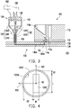
FIG. 4 is a cross-sectional view of the mixing unit ofFIG. 1 along line I-I. Furthermore, inFIG. 4 , theextension 1242 and an inner wall of thetube portion 1222 of the present embodiment have a first gap G1 therebetween in a first direction RD1 of the tube portion 1222 (that is, a radial direction perpendicular to an axial direction AD of the tube portion 1222). Theextension 1242 and the inner wall of thetube portion 1222 have a second gap G2 therebetween in a second direction RD2 of the tube portion 1222 (that is, another radial direction perpendicular to the axial direction AD of the tube portion 1222). And, the first gap G1 is smaller than the second gap G2. In other words, sizes of the gaps between theextension 1242 and the inner wall of thetube portion 1222 are not uniform. As a result, the capillary force between theextension 1242 and the inner wall of thetube portion 1222 is uneven. Therefore, when the reagent flows in themixing chamber 122 due to the drive of apump 160 and/or the stir of thestirring assembly 124, the reagent at different places in thetube portion 1222 is stirred with different flow rates. Thus, bubbles are formed easily in thetube portion 1222, and the magnetic beads and the reagent are mixed speedily by the stir of thestirring assembly 124 and the disturbance of the bubbles. - Specifically, the
tube portion 1222 of the present embodiment has acylindrical pipe 1222a, and theextension 1242 is provided in thecylindrical pipe 1222a. Theextension 1242 has a rectangular cross section, so that theextension 1242 has a first length L in the first direction RD1 and a second length W in the second direction RD2. And the first length L is greater than the second length W. This way, the sizes of the gaps between theextension 1242 and the inner wall of thetube portion 1222 may be made to be not uniform as described above. In other embodiments, thetube portion 1222 may have a pipe in other cross-sectional shapes, and theextension 1242 may have a cross section in other shapes, so that the gaps between theextension 1242 and the inner wall of thetube portion 1222 are not uniform. For example, thetube portion 1222 has a rectangular pipe, whereas theextension 1242 provided in the rectangular pipe has a circular cross section, a configuration that also includes non-uniform gaps. The present disclosure does not limit the practical shapes thereof. - In
FIG 3 , themixing unit 120 of the present embodiment includes anactuator 126 and acover 128. Thecover 128 covers thechamber portion 1221 of the mixingchamber 122. The stirringassembly 124 further includes aconnection 1243. Theconnection 1243 may pass through thecover 128 and portionally protrude to the outside of the mixingchamber 122 and connects to theactuator 126. Theactuator 126 is, for example, a motor, and is adapted to drive the stirringassembly 124 to rotate to perform the stir. In other embodiments, theactuator 126 may be other types of driving devices, and the present disclosure is not limited thereto. In addition, themixing unit 120 may also not include theactuator 126, but there be an actuator included in other external devices to drive the stirringassembly 124 to operate. - As shown in
FIG. 3 , the nucleicacid extracting device 100 of the present embodiment further includes aheating device 140, a magnetic attractingdevice 150, and apump 160. Theheating device 140 is disposed beside the mixingchamber 122, and is adapted to heat the mixingchamber 122 to accelerate a reaction rate of the specimen and the reagent. The magnetic attractingdevice 150 is disposed movably outside thetube portion 1222, and is adapted to restrict the location of the magnetic beads by magnetic attraction, so as to prevent the magnetic beads from moving away from thetube portion 1222 unexpectedly due to the flow of the reagent. Thepump 160 is connected to the mixingchamber 122 and is adapted to drive the specimen, the magnetic beads, and/or the reagent for extracting to move between thereagent containing unit 110 and the mixingchamber 122. Theheating device 140 and the magnetic attractingdevice 150 may be disposed respectively at positions adjacent to thechamber portion 1221 and thetube portion 1222 as shown inFIG. 3 , but the disclosure is not limited thereto. The nucleicacid extracting device 100 may also not include theheating device 140 and/or the magnetic attractingdevice 150, but there be a heating device and/or a magnetic attracting device included in other external devices to perform the heating and the magnetic attraction. When the heating and/or the magnetic attraction performed by theheating device 140 and/or the magnetic attractingdevice 150 is/are not required, theheating device 140 and/or the magnetic attractingdevice 150 may be driven to move away from the mixingchamber 122, or turn off theheating device 140 and/or the magnetic attractingdevice 150. In addition, the nucleicacid extracting device 100 may also not include thepump 160, but there be a pump included in other external devices to drive the specimen, the magnetic beads, and/or the reagent for extracting to flow. - In the present embodiment, the reagent for extracting may include a lysis buffer, a binding buffer, a washing buffer, and an elution buffer. As shown in
FIG. 1 , thereagent chamber 110a may be adapted to contain the specimen; thereagent chamber 110b may be adapted to contain the lysis solution; thereagent chamber 110c may be adapted to contain the binding buffer; thereagent chamber 110d may be adapted to contain the magnetic beads; thereagent chambers reagent chamber 110g may be adapted to contain the elution buffer. - The specific operation flow of the nucleic
acid extracting device 100 of the present embodiment is described below. First, the specimen in thereagent chamber 110a and the lysis buffer in thereagent chamber 110b flow from thereagent containing unit 110 through theflow channel unit 130 to the mixingchamber 122 by the drive of thepump 160. Theheating device 140 heats the mixingchamber 122, and the stirringassembly 124 stirs the specimen and the lysis buffer in the mixingchamber 122, so that cell membranes of the specimen are destroyed by the lysis buffer to precipitate nucleic acid. Then, the binding buffer in thereagent chamber 110c and the magnetic beads in thereagent chamber 110d flow sequentially from thereagent containing unit 110 through theflow channel unit 130 to the mixingchamber 122 by the drive of thepump 160. Theheating device 140 heats the mixingchamber 122, and the stirringassembly 124 stirs the specimen, the magnetic beads, and the binding buffer in the mixingchamber 122, so that the nucleic acid of the specimen is bound to the magnetic beads by the binding buffer. Then, the magnetic beads are prevented from moving by the magnetic attraction of the magnetic attractingdevice 150, and waste liquid generated by the reaction between the specimen and the reagent in the mixingchamber 122 is driven by thepump 160 to pass through theflow channel unit 130 to be discharged to thereagent containing unit 110; and thereagent containing unit 110 may include a waste liquid chamber or use an existing reagent chamber to contain the waste liquid. - Next, the washing buffer in the
reagent chamber 110e flows from thereagent containing unit 110 through theflow channel unit 130 to the mixingchamber 122 by the drive of thepump 160. The stirringassembly 124 stirs the magnetic beads and the washing buffer in the mixingchamber 122 to wash the magnetic beads for the first time with the washing buffer. The magnetic attraction force of the magnetic attractingdevice 150 prevents the magnetic beads from moving, and thepump 160 drives the waste liquid generated in the mixingchamber 122 after the first wash to pass through theflow channel unit 130 to be discharged to thereagent containing unit 110; and thereagent containing unit 110 may include a waste liquid chamber or use an existing reagent chamber to contain the waste liquid. Then, the washing buffer in thereagent chamber 110f flows from thereagent containing unit 110 through theflow channel unit 130 to the mixingchamber 122 by the drive of thepump 160. The stirringassembly 124 stirs the magnetic beads and the washing buffer in the mixingchamber 122 to wash the magnetic beads for the second time with the washing buffer. The magnetic attraction force of the magnetic attractingdevice 150 prevents the magnetic beads from moving, and thepump 160 drives the waste liquid generated in the mixingchamber 122 after the second wash to pass through theflow channel unit 130 to be discharged to thereagent containing unit 110; and thereagent containing unit 110 may include a waste liquid chamber or use an existing reagent chamber to contain the waste liquid. The elution buffer in thereagent chamber 110g flows from thereagent containing unit 110 through theflow channel unit 130 to the mixingchamber 122 by the drive of thepump 160. The stirringassembly 124 stirs the magnetic beads and the elution buffer in the mixingchamber 122 to separate the nucleic acid from the magnetic beads with the elution buffer, and thereby extracting the nucleic acid. - In different steps of the foregoing operation flow, the amount of reagents in the mixing
chamber 122 may be different. To make the mixingchamber 122 suitable for various amounts of reagents, a connecting end of thechamber portion 1221 to thetube portion 1222 may be designed to be funnel-shaped as shown inFIG. 1 to FIG. 3 , such that inner widths of parts of thechamber portion 1221 gradually taper from top to bottom. This way, when the amount of the reagent in the mixingchamber 122 is large, the part with a larger inner width is capable of providing enough space to contain the reagent, and when the amount of the reagent in the mixingchamber 122 is small, the part with a smaller inner width is capable of preventing the reagent from being excessively dispersed in a horizontal direction due to the excessive width of the mixingchamber 122, so as to reduce the residual in corners of thechamber portion 1221. Correspondingly, the shape of the funnel-shaped part of themain body 1241 of the stirringassembly 124 provided in thechamber portion 1221 may also be changed accordingly. Specifically, themain body 1241 of the stirringassembly 124, which is disposed at the corresponding tapered part of thechamber portion 1221, may be designed as an airfoil and taper toward theextension 1242, so that even a small amount of reagent may be well stirred. -
FIG. 5 is an exploded-view drawing of the reagent containing unit ofFIG. 1 . InFIG. 3 andFIG. 5 , thereagent containing unit 110 of the present embodiment includes a containingstructure 112. Thereagent chambers 110a to 110g are formed in the containingstructure 112. A bottom of the containingstructure 112 has a plurality ofchannels 112a, and thechannels 112a are respectively connected to thereagent chambers 110a to 110g. And each of thereagent chambers 110a to 110g communicates with theflow channel unit 130 through the correspondingchannel 112a. - Furthermore, the
reagent containing unit 110 further includes a plurality ofelastic seals 114 and abottom plate 116. Theelastic seals 114 are disposed at the bottom of the containingstructure 112 and are corresponding respectively to thechannels 112a. Thebottom plate 116 is assembled to the bottom of the containingstructure 112, for example, in a screw-locked manner, and each of theelastic seals 114 is restricted between the containingstructure 112 and theflow channel unit 130.FIG. 6 is a locally enlarged view of the nucleicacid extracting device 100 ofFIG. 3 . InFIG. 6 , each of theelastic seals 114 has a throughhole 114c as well as atop surface 114a and abottom surface 114b opposite to each other. The throughhole 114c extends from thetop surface 114a to thebottom surface 114b. Each of theelastic seals 114 is disposed in thebottom plate 116, and thetop surface 114a and thebottom surface 114b of eachelastic seal 114 respectively contact the containingstructure 112 and theflow channel unit 130. The throughhole 114c communicates with the correspondingchannel 112a, so that each of thereagent chambers 110a to 110g may communicate with theflow channel unit 130 through the correspondingchannel 112a and the corresponding throughhole 114c. The material of eachelastic seal 114 may be rubber or other elastic material suitable to perform sealing between the containingstructure 112 and theflow channel unit 130, such that unexpected leakage of the reagent there may be prevented. In addition, each of thechannels 112a of the containingstructure 112 is, for example, a capillary, and the capillary resistance thereof further prevents the reagent from leaking. - Specifically, each of the
elastic seals 114 is disposed in theopening 116a of thebottom plate 116. And each of theelastic seals 114 is in a stepped shape as shown inFIG. 6 , and may be restricted by aflange 116b in theopening 116a to be at the bottom of thecontainment structure 112. The throughhole 114c of eachelastic seal 114 is adapted to communicate with an end 130a1 (marked inFIG. 6 ) of theflow channel 130a (marked inFIG. 2 andFIG. 3 ) provided between theupper plate body 132 and thelower plate body 134 of theflow channel unit 130. - In the present embodiment, the
flow channel unit 130 has, for example, only oneflow channel 130a, and one end of theflow channel 130a is connected to the mixingchamber 122. Thereagent containing unit 110 is rotatably disposed on theflow channel unit 130 along a rotation axis RA (shown inFIG. 1 ) and is adapted to rotate, so that any one of thereagent chambers 110a to 110g may be correspond to the other end of theflow channel 130a (i.e., the end 130a1 shown inFIG. 6 ), such that one of thereagent chambers 110a to 110g communicates with the mixingchamber 122. In the present embodiment, thereagent containing unit 110 rotates via the drive of, for example, a motor or other suitable drivers. In other embodiments, the communication between thereagent chambers 110a to 110g and the mixingchamber 122 may also be switched by adopting other suitable methods and/or structures, and the present disclosure is not limited thereto. -
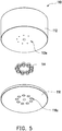
FIG. 7 is a locally enlarged view of the containing structure ofFIG. 1 . InFIG. 7 , in the present embodiment, thereagent chamber 110d corresponding to the magnetic beads has an inlet 110d1, an outlet 110d2, and a guide surface 110d3, and a bottom of thereagent chamber 110d has a recess 110d4. The outlet 110d2 is provided in the recess 110d4, and the recess 110d4 is adapted to contain the magnetic beads. The location of theinlet 110d is higher than the location of the outlet 110d2, and the guide surface 110d3 extends obliquely from the inlet 110d1 to the outlet 110d2. When the magnetic beads are to be moved to the mixingchamber 122 shown inFIG. 1 , a suitable reagent may be driven to enter thereagent chamber 110d from the inlet 110d1, so that the reagent drives the magnetic beads to move out of thereagent chamber 110d from the outlet 110d2 and move to the mixingchamber 122 through theflow channel unit 130. Since the magnetic beads are collected to the lower recess 110d4 in advance, and the reagent flows downward from the inlet 110d1 which is above the location of the outlet 110d2, and drives the magnetic beads to move away from thereagent chamber 110d through the outlet 110d2, the magnetic beads are prevented from dashing out of thereagent chamber 110d due to the impact of the reagent. -
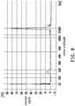
FIG. 8 shows a corresponding detection signal of the nucleic acid extracted by the nucleic acid extracting device ofFIG. 1 . As shown inFIG. 8 , a significant detection signal appears between the nucleic acid length of 150 bp to 200 bp, indicating that the nucleicacid extracting device 100 of the present embodiment indeed extracts nucleic acid from the specimen. - In sum, in addition to the existing chamber, the mixing chamber of the present disclosure further includes a tube portion extending from the chamber portion, and the stirring assembly correspondingly includes an extension that extends into the tube portion. In addition, there are the first gap and the second gap of different sizes between the extension of the stirring assembly and the inner wall of the tube portion. In other words, the sizes of the gaps between the extension and the inner wall of the tube portion are not made uniformly. The non-uniform gaps between the extension of the stirring assembly and the tube portion cause the liquid to produce uneven capillary force. When the pump sucks air from the upper end of the mixing chamber, the liquid flows up and down in the tube portion repeatedly, re-dissolving the magnetic beads that are attached to the tube wall.
- It will be apparent to those skilled in the art that various modifications and variations can be made to the structure of the disclosed embodiments without departing from the scope or spirit of the disclosure. In view of the foregoing, it is intended that the disclosure cover modifications and variations of the present disclosure provided they fall within the scope of the following claims and their equivalents.
Claims (21)
- A nucleic acid extracting device (100), comprising:a reagent containing unit (110), adapted to contain at least one specimen, at least one magnetic bead, and at least one reagent for extracting;a mixing unit (120), comprising a mixing chamber (122) and a stirring assembly (124), wherein the mixing chamber (122) comprises a chamber portion (1221) and a tube portion (1222), the stirring assembly (124) comprises a main body (1241) and an extension (1242), the main body (1241) is provided in the chamber portion (1221), the tube portion (1222) connects to the chamber portion (1221), the extension (1242) connects to the main body (1241) and extends into the tube portion (1222), the extension (1242) and an inner wall of the tube portion (1222) comprises a first gap (G1) therebetween in a first direction (RD1) of the tube portion (1222), the extension (1242) and the inner wall of the tube portion (1222) comprises a second gap (G2) therebetween in a second direction (RD2) of the tube portion (1222), and the first gap (G1) is smaller than the second gap (G2); anda flow channel unit (130), connected between the reagent containing unit (110) and the mixing unit (120), wherein the at least one specimen, the at least one magnetic bead, and the at least one reagent for extracting are adapted to flow from the reagent containing unit (110) through the flow channel unit (130) to the mixing chamber (122) to be stirred and mixed by the stirring assembly (124).
- The nucleic acid extracting device (100) according to claim 1, wherein an inner width of the tube portion (1222) is smaller than an inner width of the chamber portion (1221).
- The nucleic acid extracting device (100) according to claim 1, wherein an inner width of at least part of the chamber portion (1221) tapers from top to bottom, and the main body (1241) disposed in a corresponding tapered part of the chamber portion (1221) is provided in an airfoil shape.
- The nucleic acid extracting device (100) according to claim 1, wherein a width of the extension (1242) is smaller than a width of the main body (1241).
- The nucleic acid extracting device (100) according to claim 1, wherein the tube portion (1222) is connected between the flow channel unit (130) and the chamber portion (1221).
- The nucleic acid extracting device (100) according to claim 1, wherein the extension (1242) comprises a first length (L) in the first direction (RD1) and a second length (W) in the second direction (RD2), and the first length (L) is greater than the second length (W).
- The nucleic acid extracting device (100) according to claim 1, wherein the tube portion (1222) comprises a cylindrical pipe (1222a), and the extension (1242) is provided in the cylindrical pipe (1222a) and comprises a rectangular cross section.
- The nucleic acid extracting device (100) according to claim 1, wherein the tube portion (1222) comprises a rectangular pipe, and the extension (1242) is provided in the rectangular pipe and comprises a circular cross section.
- The nucleic acid extracting device (100) according to claim 1, wherein the mixing unit (120) comprises an actuator (126), and the actuator (126) is connected to the stirring assembly (124) and is adapted to drive the stirring assembly (124) to rotate.
- The nucleic acid extracting device (100) according to claim 1, further comprising a heating device (140), wherein the heating device (140) is disposed beside the mixing chamber (122) and is adapted to heat the mixing chamber (122).
- The nucleic acid extracting device (100) according to claim 1, further comprising a magnetic attracting device (150), wherein the magnetic attracting device (150) is disposed movably outside the tube portion (1222) and is adapted to prevent the at least one magnetic bead from moving away from the tube portion (1222) by magnetic attraction.
- The nucleic acid extracting device (100) according to claim 1, further comprising a pump (160), wherein the pump (160) is connected to the mixing chamber (122) and is adapted to drive the at least one specimen, the at least one magnetic bead, and the at least one reagent for extracting to move between the reagent containing unit (110) and the mixing chamber (122).
- The nucleic acid extracting device (100) according to claim 1, wherein the reagent containing unit (110) comprises a plurality of reagent chambers (110a, 110b, 110c, 110d, 110e, 110f, 110g), and the plurality of reagent chambers (110a, 110b, 110c, 110d, 110e, 110f, 110g) are adapted to contain respectively the at least one specimen, the at least one magnetic bead, and the at least one reagent for extracting.
- The nucleic acid extracting device (100) according to claim 13, wherein the at least one reagent for extracting comprises a lysis solution, a binding buffer, a washing buffer, and an elution buffer, and part of the plurality of reagent chambers (110a, 110b, 110c, 110d, 110e, 11Of, 110g) are adapted to contain respectively the lysis solution, the binding buffer, the washing buffer, and the elution buffer.
- The nucleic acid extracting device (100) according to claim 13, wherein one reagent chamber (110d) of the plurality of reagent chambers (110a, 110b, 110c, 110d, 110e, 11Of, 110g) corresponding to contain the at least one magnetic bead comprises an inlet (110d1) and an outlet (110d2), and a location of the inlet (110d1) is higher than a location of the outlet (110d2).
- The nucleic acid extracting device (100) according to claim 15, wherein the reagent chamber (110d) corresponding to contain the at least one magnetic bead comprises a guide surface (110d3), and the guide surface (110d3) extends obliquely from the inlet (110d1) to the outlet (110d2).
- The nucleic acid extracting device (100) according to claim 15, wherein a bottom of the reagent chamber (110d) corresponding to contain the at least one magnetic bead comprises a recess (110d4), the outlet (110d2) is provided in the recess (110d4), and the recess (110d4) is adapted to contain the at least one magnetic bead.
- The nucleic acid extracting device (100) according to claim 13, wherein the reagent containing unit (110) comprises a containing structure (112), the plurality of reagent chambers (110a, 110b, 110c, 110d, 110e, 110f, 110g) are formed in the containing structure (112), a bottom of the containing structure (112) comprises a plurality of channels (112a), the plurality of channels (112a) are connected respectively to the plurality of reagent chambers (110a, 110b, 110c, 110d, 110e, 110f, 110g), and each of the plurality of reagent chambers (110a, 110b, 110c, 110d, 110e, 11Of, 110g) communicates with the flow channel unit (130) via a corresponding channel of the plurality of channels (112a).
- The nucleic acid extracting device (100) according to claim 18, wherein each of the plurality of channels (112a) is a capillary.
- The nucleic acid extracting device (100) according to claim 18, wherein the reagent containing unit (110) further comprises a plurality of elastic seals (114) and a bottom plate (116), the plurality of elastic seals (114) are disposed at the bottom of the containing structure (112) and are corresponding to the plurality of channels (112a) respectively, the bottom plate (116) is assembled at the bottom of the containing structure (112) and each of the plurality of elastic seals (114) is restricted between the containing structure (112) and the flow channel unit (130), each of the plurality of elastic seals (114) comprises a through hole (114c) as well as a top surface (114a) and a bottom surface (114b) opposite to each other, the through hole (114c) extends from the top surface (114a) to the bottom surface (114b), each of the plurality of elastic seals (114) is disposed in the bottom plate (116), the top surface (114a) and the bottom surface (114b) respectively contact the containing structure (112) and the flow channel unit (130), and the through hole (114c) connects to the corresponding channel of the plurality of channels (112a).
- The nucleic acid extracting device (100) according to claim 13, wherein the flow channel unit (130) comprises a flow channel (130a), an end of the flow channel (130a) is connected to the mixing chamber (122), and the reagent containing unit (110) is disposed rotatably on the flow channel unit (130) and is adapted to rotate, so that any one of the plurality of reagent chambers (110a, 110b, 110c, 110d, 110e, 110f, 110g) corresponds to the other end (130a1) of the flow channel (130a).
Applications Claiming Priority (1)
| Application Number | Priority Date | Filing Date | Title |
|---|---|---|---|
| US201962945897P | 2019-12-10 | 2019-12-10 |
Publications (1)
| Publication Number | Publication Date |
|---|---|
| EP3842134A1 true EP3842134A1 (en) | 2021-06-30 |
Family
ID=74184344
Family Applications (1)
| Application Number | Title | Priority Date | Filing Date |
|---|---|---|---|
| EP20212678.5A Pending EP3842134A1 (en) | 2019-12-10 | 2020-12-09 | Nucleic acid extracting device |
Country Status (3)
| Country | Link |
|---|---|
| EP (1) | EP3842134A1 (en) |
| JP (1) | JP7101746B2 (en) |
| TW (1) | TWI742905B (en) |
Cited By (2)
| Publication number | Priority date | Publication date | Assignee | Title |
|---|---|---|---|---|
| CN113583807A (en) * | 2021-08-25 | 2021-11-02 | 无锡正则精准医学检验有限公司 | Nucleic acid extraction instrument for colorectal cancer detection |
| CN116286269A (en) * | 2023-03-28 | 2023-06-23 | 重庆国科医创科技发展有限公司 | A nucleic acid extraction device and method |
Families Citing this family (1)
| Publication number | Priority date | Publication date | Assignee | Title |
|---|---|---|---|---|
| TWI876543B (en) * | 2022-09-20 | 2025-03-11 | 台達電子工業股份有限公司 | Combinable nucleic acid pre-processing apparatus |
Citations (4)
| Publication number | Priority date | Publication date | Assignee | Title |
|---|---|---|---|---|
| WO2006032044A2 (en) * | 2004-09-15 | 2006-03-23 | Microchip Biotechnologies, Inc. | Microfluidic devices |
| WO2006136999A1 (en) * | 2005-06-23 | 2006-12-28 | Koninklijke Philips Electronics N.V. | Device for mixing a liquid medium |
| WO2010091080A2 (en) * | 2009-02-03 | 2010-08-12 | Network Biosystems, Inc. | Nucleic acid purification |
| WO2014066704A1 (en) * | 2012-10-24 | 2014-05-01 | Genmark Diagnostics, Inc. | Integrated multiplex target analysis |
Family Cites Families (13)
| Publication number | Priority date | Publication date | Assignee | Title |
|---|---|---|---|---|
| US6374684B1 (en) | 2000-08-25 | 2002-04-23 | Cepheid | Fluid control and processing system |
| GB0227765D0 (en) | 2002-11-28 | 2003-01-08 | Secr Defence | Apparatus for processing a fluid sample |
| JP2008241250A (en) | 2007-03-23 | 2008-10-09 | Olympus Corp | Stirring rod using specifically binding reaction, and analyzing method and device using stirring rod thereof |
| JP2011128019A (en) | 2009-12-17 | 2011-06-30 | Hitachi Maxell Ltd | Microplate device and utilization of the same |
| JP2015159754A (en) * | 2014-02-27 | 2015-09-07 | セイコーエプソン株式会社 | Nucleic acid amplification method, nucleic acid extraction device, nucleic acid amplification reaction cartridge, and nucleic acid amplification reaction kit |
| CN104059848A (en) | 2014-06-26 | 2014-09-24 | 广州冠科生物科技有限公司 | Uniform mixing device for nucleic acid extraction |
| CN105441318B (en) * | 2014-08-15 | 2018-02-13 | 冠研(上海)专利技术有限公司 | It is configured with the nucleic acid product extraction equipment of barriers |
| ES3038141T3 (en) | 2014-11-11 | 2025-10-09 | Hoffmann La Roche | Fluid sample processing cartridge |
| WO2016195963A1 (en) * | 2015-05-29 | 2016-12-08 | Tsavachidou Dimitra | Methods for constructing consecutively connected copies of nucleic acid molecules |
| KR20190022711A (en) | 2016-06-24 | 2019-03-06 | 론자 리미티드 | Variable diameter bioreactor |
| TWI611171B (en) | 2016-12-14 | 2018-01-11 | 財團法人工業技術研究院 | Biological sample processing device |
| TW201903147A (en) * | 2017-06-13 | 2019-01-16 | 益生生技開發股份有限公司 | Method and apparatus for extracting nucleic acid |
| JP2019176831A (en) | 2018-03-30 | 2019-10-17 | 大研医器株式会社 | Method and vessel for recovering nucleic acid |
-
2020
- 2020-11-03 TW TW109138168A patent/TWI742905B/en active
- 2020-12-09 JP JP2020204321A patent/JP7101746B2/en active Active
- 2020-12-09 EP EP20212678.5A patent/EP3842134A1/en active Pending
Patent Citations (4)
| Publication number | Priority date | Publication date | Assignee | Title |
|---|---|---|---|---|
| WO2006032044A2 (en) * | 2004-09-15 | 2006-03-23 | Microchip Biotechnologies, Inc. | Microfluidic devices |
| WO2006136999A1 (en) * | 2005-06-23 | 2006-12-28 | Koninklijke Philips Electronics N.V. | Device for mixing a liquid medium |
| WO2010091080A2 (en) * | 2009-02-03 | 2010-08-12 | Network Biosystems, Inc. | Nucleic acid purification |
| WO2014066704A1 (en) * | 2012-10-24 | 2014-05-01 | Genmark Diagnostics, Inc. | Integrated multiplex target analysis |
Non-Patent Citations (1)
| Title |
|---|
| LIU R H ET AL: "Bubble-induced acoustic micromixing", LAB ON A CHIP, ROYAL SOCIETY OF CHEMISTRY, vol. 2, 1 January 2002 (2002-01-01), pages 151 - 157, XP009103055, ISSN: 1473-0197, DOI: 10.1039/B201952C * |
Cited By (2)
| Publication number | Priority date | Publication date | Assignee | Title |
|---|---|---|---|---|
| CN113583807A (en) * | 2021-08-25 | 2021-11-02 | 无锡正则精准医学检验有限公司 | Nucleic acid extraction instrument for colorectal cancer detection |
| CN116286269A (en) * | 2023-03-28 | 2023-06-23 | 重庆国科医创科技发展有限公司 | A nucleic acid extraction device and method |
Also Published As
| Publication number | Publication date |
|---|---|
| TWI742905B (en) | 2021-10-11 |
| TW202122566A (en) | 2021-06-16 |
| JP7101746B2 (en) | 2022-07-15 |
| JP2021090420A (en) | 2021-06-17 |
Similar Documents
| Publication | Publication Date | Title |
|---|---|---|
| US12521711B2 (en) | Genome extraction device including flow cover | |
| US12303885B2 (en) | Genome extraction device including safety clip combined with inner chamber | |
| Zhu et al. | Self-priming compartmentalization digital LAMP for point-of-care | |
| US9644623B2 (en) | Fluid control structures in microfluidic devices | |
| CN104741157B (en) | Device for isolating cells from heterogeneous solution using microfluidic trapping vortices | |
| TWI742905B (en) | Nucleic acid extracting device | |
| US11733258B2 (en) | Nucleic acid extracting device | |
| CN110841730B (en) | A microfluidic chip and tumor DNA detection chip | |
| CN111602060A (en) | Nucleic acid extraction method using extraction cassette | |
| CN1800858A (en) | Chemical analysis apparatus and chemical analysis cartridge | |
| CN1791509A (en) | Method and apparatus for detecting and analyzing pathogens | |
| CN118022873A (en) | Fluid-tight flow system for separating biomarkers from liquid samples | |
| US20220410142A1 (en) | Amplification module with gas moving passage and extract moving passage | |
| JP6956786B2 (en) | Microfluidic devices and methods for analyzing nucleic acids | |
| CN105734045A (en) | Quick multi-flux blood sample DNA extraction method based on micro-fluidic chip | |
| US20220410150A1 (en) | Genome extraction device of dual chamber structure in which outer chamber and inner chamber are combined with each other | |
| CN101748204B (en) | Nucleic acid hybridized platform based on micro-flow control and hybridization analysis method thereof | |
| CN117730158A (en) | Microfluidic chip, nucleic acid extraction equipment and nucleic acid extraction method | |
| CN105854347A (en) | Circumferential array type micro-fluid extraction device | |
| CN111389474B (en) | A microfluidic chip for sample dispersion and its preparation method and application | |
| CN209669229U (en) | A microfluidic chip for detection of canine virus by fluorescent quantitative PCR | |
| CN118853349A (en) | A multi-stage sorting device and method for marine microbial particles based on U-shaped microfluidic chip | |
| CN1551982A (en) | Chemical analysis equipment and genetic diagnosis equipment | |
| CN117181326A (en) | Flow channel structure, centrifugal microfluidic chip and use method thereof | |
| JP2008543324A (en) | Apparatus for mixing liquid media |
Legal Events
| Date | Code | Title | Description |
|---|---|---|---|
| PUAI | Public reference made under article 153(3) epc to a published international application that has entered the european phase |
Free format text: ORIGINAL CODE: 0009012 |
|
| STAA | Information on the status of an ep patent application or granted ep patent |
Free format text: STATUS: REQUEST FOR EXAMINATION WAS MADE |
|
| 17P | Request for examination filed |
Effective date: 20201209 |
|
| AK | Designated contracting states |
Kind code of ref document: A1 Designated state(s): AL AT BE BG CH CY CZ DE DK EE ES FI FR GB GR HR HU IE IS IT LI LT LU LV MC MK MT NL NO PL PT RO RS SE SI SK SM TR |
|
| RBV | Designated contracting states (corrected) |
Designated state(s): AL AT BE BG CH CY CZ DE DK EE ES FI FR GB GR HR HU IE IS IT LI LT LU LV MC MK MT NL NO PL PT RO RS SE SI SK SM TR |