EP3842092B1 - A device for transcutaneous application of carbon dioxide - Google Patents
A device for transcutaneous application of carbon dioxide Download PDFInfo
- Publication number
- EP3842092B1 EP3842092B1 EP19219593.1A EP19219593A EP3842092B1 EP 3842092 B1 EP3842092 B1 EP 3842092B1 EP 19219593 A EP19219593 A EP 19219593A EP 3842092 B1 EP3842092 B1 EP 3842092B1
- Authority
- EP
- European Patent Office
- Prior art keywords
- chamber
- valve
- outlet pipe
- inlet
- air
- Prior art date
- Legal status (The legal status is an assumption and is not a legal conclusion. Google has not performed a legal analysis and makes no representation as to the accuracy of the status listed.)
- Active
Links
Images


Classifications
-
- A—HUMAN NECESSITIES
- A61—MEDICAL OR VETERINARY SCIENCE; HYGIENE
- A61G—TRANSPORT, PERSONAL CONVEYANCES, OR ACCOMMODATION SPECIALLY ADAPTED FOR PATIENTS OR DISABLED PERSONS; OPERATING TABLES OR CHAIRS; CHAIRS FOR DENTISTRY; FUNERAL DEVICES
- A61G10/00—Treatment rooms or enclosures for medical purposes
- A61G10/02—Treatment rooms or enclosures for medical purposes with artificial climate; with means to maintain a desired pressure, e.g. for germ-free rooms
- A61G10/023—Rooms for the treatment of patients at over- or under-pressure or at a variable pressure
-
- A—HUMAN NECESSITIES
- A61—MEDICAL OR VETERINARY SCIENCE; HYGIENE
- A61M—DEVICES FOR INTRODUCING MEDIA INTO, OR ONTO, THE BODY; DEVICES FOR TRANSDUCING BODY MEDIA OR FOR TAKING MEDIA FROM THE BODY; DEVICES FOR PRODUCING OR ENDING SLEEP OR STUPOR
- A61M35/00—Devices for applying media, e.g. remedies, on the human body
- A61M35/30—Gas therapy for therapeutic treatment of the skin
-
- A—HUMAN NECESSITIES
- A61—MEDICAL OR VETERINARY SCIENCE; HYGIENE
- A61H—PHYSICAL THERAPY APPARATUS, e.g. DEVICES FOR LOCATING OR STIMULATING REFLEX POINTS IN THE BODY; ARTIFICIAL RESPIRATION; MASSAGE; BATHING DEVICES FOR SPECIAL THERAPEUTIC OR HYGIENIC PURPOSES OR SPECIFIC PARTS OF THE BODY
- A61H33/00—Bathing devices for special therapeutic or hygienic purposes
- A61H33/14—Devices for gas baths with ozone, hydrogen, or the like
-
- A—HUMAN NECESSITIES
- A61—MEDICAL OR VETERINARY SCIENCE; HYGIENE
- A61H—PHYSICAL THERAPY APPARATUS, e.g. DEVICES FOR LOCATING OR STIMULATING REFLEX POINTS IN THE BODY; ARTIFICIAL RESPIRATION; MASSAGE; BATHING DEVICES FOR SPECIAL THERAPEUTIC OR HYGIENIC PURPOSES OR SPECIFIC PARTS OF THE BODY
- A61H35/00—Baths for specific parts of the body
-
- A—HUMAN NECESSITIES
- A61—MEDICAL OR VETERINARY SCIENCE; HYGIENE
- A61M—DEVICES FOR INTRODUCING MEDIA INTO, OR ONTO, THE BODY; DEVICES FOR TRANSDUCING BODY MEDIA OR FOR TAKING MEDIA FROM THE BODY; DEVICES FOR PRODUCING OR ENDING SLEEP OR STUPOR
- A61M16/00—Devices for influencing the respiratory system of patients by gas treatment, e.g. ventilators; Tracheal tubes
- A61M16/0057—Pumps therefor
-
- A—HUMAN NECESSITIES
- A61—MEDICAL OR VETERINARY SCIENCE; HYGIENE
- A61M—DEVICES FOR INTRODUCING MEDIA INTO, OR ONTO, THE BODY; DEVICES FOR TRANSDUCING BODY MEDIA OR FOR TAKING MEDIA FROM THE BODY; DEVICES FOR PRODUCING OR ENDING SLEEP OR STUPOR
- A61M16/00—Devices for influencing the respiratory system of patients by gas treatment, e.g. ventilators; Tracheal tubes
- A61M16/20—Valves specially adapted to medical respiratory devices
- A61M16/208—Non-controlled one-way valves, e.g. exhalation, check, pop-off non-rebreathing valves
-
- A—HUMAN NECESSITIES
- A61—MEDICAL OR VETERINARY SCIENCE; HYGIENE
- A61H—PHYSICAL THERAPY APPARATUS, e.g. DEVICES FOR LOCATING OR STIMULATING REFLEX POINTS IN THE BODY; ARTIFICIAL RESPIRATION; MASSAGE; BATHING DEVICES FOR SPECIAL THERAPEUTIC OR HYGIENIC PURPOSES OR SPECIFIC PARTS OF THE BODY
- A61H33/00—Bathing devices for special therapeutic or hygienic purposes
- A61H33/14—Devices for gas baths with ozone, hydrogen, or the like
- A61H2033/145—Devices for gas baths with ozone, hydrogen, or the like with CO2
-
- A—HUMAN NECESSITIES
- A61—MEDICAL OR VETERINARY SCIENCE; HYGIENE
- A61H—PHYSICAL THERAPY APPARATUS, e.g. DEVICES FOR LOCATING OR STIMULATING REFLEX POINTS IN THE BODY; ARTIFICIAL RESPIRATION; MASSAGE; BATHING DEVICES FOR SPECIAL THERAPEUTIC OR HYGIENIC PURPOSES OR SPECIFIC PARTS OF THE BODY
- A61H35/00—Baths for specific parts of the body
- A61H2035/004—Baths for specific parts of the body for the whole body except the head
-
- A—HUMAN NECESSITIES
- A61—MEDICAL OR VETERINARY SCIENCE; HYGIENE
- A61M—DEVICES FOR INTRODUCING MEDIA INTO, OR ONTO, THE BODY; DEVICES FOR TRANSDUCING BODY MEDIA OR FOR TAKING MEDIA FROM THE BODY; DEVICES FOR PRODUCING OR ENDING SLEEP OR STUPOR
- A61M2202/00—Special media to be introduced, removed or treated
- A61M2202/02—Gases
- A61M2202/0225—Carbon oxides, e.g. Carbon dioxide
Definitions
- the present invention belongs to the field of medical devices for treatment with carbon dioxide, more precisely to the field of devices for transcutaneous application of carbon dioxide.
- the invention also belongs to the field of piping, connections and valves for medical devices and medical use.
- the invention relates to a device for transcutaneous application of carbon dioxide for treatment of chronic wounds and/or neuropathy.
- CO 2 can be applied to treat a variety of disorders, mostly treatment for peripheral vascular disorders ( Dogliotti et al, 2011, Int Angiol. 30(1):12-7 .).
- the benefits of bathing in CO 2 -enriched water have been described (Hartmann et al, 1997, https://doi.org/10.1177/000331979704800406; Toriyama et al., 2002, Int Angiol. 21(4):367-73 ).
- Bohr effect Irie et al, 2005, Circulation 111:1523-1529 ; Bohr et al., 1904, https://doi.org/10.1111/j.1748-1716.1904.tb01382.x).
- the Bohr effect indeed occurs in human body after transcutaneous administration of CO 2 as shown by Sakai et al. (2011, PloS One, 6, 9: e24137 ).
- CO 2 therapy is performed by bathing in CO 2 enriched water or by injection, wherein transcutaneous CO 2 application using 100% CO 2 gas is supported by applying CO 2 absorption-enhancing hydrogel (Onishi et al, 2012).
- CO 2 enriched water is prepared by supplying CO 2 in gaseous form from tanks, however the amount of CO 2 in water is small, due to potential danger of inhaling toxic amounts of CO 2 . It has been estimated that the concentration of CO 2 in the enriched water is only 0.1 % and there is no evidence showing absorption in human body ( Hashimoto et al, 2004, J Appl Physiol 96:226-232 ; Yamamoto et al, 2007, Int J Biometeorol 51:201-208 ). Further, such bathing is not suitable for hospital treatments and for patients with chronic or acute wounds.
- a chronic wound is a wound that does not heal in a usual manner and it is widely accepted that wounds that do not heal within three months are considered chronic.
- Chronic wounds have different causes (ischemic, neuropathic, etc.) and may differ in the stage of healing in which they are detained. In some cases, such wounds may never heal or take years to do so.
- Delayed wound healing has also been linked to peripheral neuropathy, which is a condition where peripheral nerves are damaged and cause various unpleasant sensations, including pain. Peripheral neuropathy can be a result of several different causes - traumatic injuries, infections, metabolic problems, inherited causes and exposure to toxins, however one of the most common causes is diabetes. In patients with this metabolic condition, nerve damage tends to lead to a loss of sensation in limbs, usually feet. Wounds on the lower extremities are often overlooked, resulting in delayed wound care and untreated infection that, if it turns gangrenous, may need to be amputated to stop the spread.
- Sakai et al (2011, PloS One, 6, 9: e24137 ) used a device for transcutaneous CO 2 delivery comprising a wrap for covering a part of the body and allowing supply of 100% CO 2 together with a hydrogel, so that the supplied CO 2 remained in the wrap. Similar approach was used by Ueha et al (2017; https://doi.org/10.3892/or.2017.5591), where transcutaneous administration of CO 2 to the area of skin around the tumour was achieved with a CO 2 hydrogel. The area was then sealed with a polyethylene bag, and 100% CO 2 gas was delivered into the bag.
- the solution shown on the web page https://www.airjectorvet.com/ comprises a bag placed around the part of an animal that has to be treated with CO 2 .
- the latter is introduced into the sealed bag with an especially adapted gun. After the treatment the CO 2 is released into the environment, which must be an open space to prevent intoxications with the gas.
- This solution differs from the present invention in many aspects, most importantly the gun does not allow introduction of concentrated CO 2 into the bag. Further, the present invention has a controlled release of CO 2 so that users of the device and the medical staff are safe.
- Patent application WO2018142171 discloses an apparatus adapted for transcutaneous treatment by gas.
- the apparatus comprises a rigid-wall cabinet and having an upper opening and at least one openable panel, wherein a seat is arranged inside the cabinet, and the cabinet comprises at least one gas concentration measurement unit, and the cabinet further comprises a gas inlet for feeding the treatment gas and a gas outlet for discharging the treatment gas; a gas supply unit coupled to the gas inlet of the cabinet via a pipe and through an interposed controllable valve; and a gas tank connected to the gas supply unit.
- the apparatus further comprises a ventilation unit connected to the gas outlet of the cabinet through an interposed controllable valve, said ventilation unit being coupled via a further pipe to a space hermetically separated from the room containing the cabinet, and wherein said ventilation unit is designed so that it can discharge the entire volume of the treatment gas from the inner space of the cabinet within at most 5 seconds.
- the apparatus further comprises a control unit for receiving the signals of the gas concentration measurement unit and for controlling operation of the valves and said ventilation unit based on at least the signals of the gas concentration measurement unit.
- Patent application US2013079703 describes a method of carbon dioxide gas treatment for improvement or promotion of circulation of blood in an ischemic region.
- the following steps (a) to (d) are continued at least once per day for four weeks, that is, a step (a) of pulverizing and dissolving carbon dioxide gas into a liquid, and producing a carbon dioxide gas mist by forming the same into a mist; a step (b) of spraying the carbon dioxide gas mist into a carbon dioxide gas mist-enclosing means for enclosing the living organism in an air tight state, a step (c) of expelling gas existing in the carbon dioxide gas mist-enclosing means into the outside, if necessary in parallel with the step (b), in order to maintain the pressure of gas within the carbon dioxide gas mist-enclosing means at or above a prescribed value being higher than the atmospheric pressure, and a step (d) of continuing such a step of supplying, for at least 20 minutes, the carbon dioxide mist into the carbon dioxide gas mist
- Utility model DE20307743 discloses a carbon dioxide skin absorption treatment unit that a sack like element with a gas tight closure fixed to a folding box with regulator inlet from the CO 2 tank and gas warming and humidifying unit and inflatable pillow and bed. This solution is not for medical use as the device does not allow leak-free emptying of the unit, which may lead to significant amounts of CO 2 into air inhaled by the user.
- the present invention solves the above-mentioned disadvantages of the known solutions.
- the invention is intended for performing transcutaneous CO 2 application treatments of all kinds of chronic or acute wounds and conditions where the basic problem is insufficient blood supply and is defined in the appended claims.
- Transcutaneous CO 2 administration is enabled by law of diffusion from the part with high CO 2 concentration (chamber of the device) to the part with a lower CO 2 concentration (the patient's body or body part).
- the part with high CO 2 concentration chamber of the device
- the part with a lower CO 2 concentration the patient's body or body part.
- the essence of the device for transcutaneous application of carbon dioxide for treatment of chronic wounds or neuropathy is in that the device comprises at least:
- the outlet pipe is connected to the inlet/outlet pipe through the first pipe of the CO 2 distribution system.
- the device can be further provided with a filter in the CO 2 distribution system to filter out any impurities and/or a silencer for decreasing the sound resulting from the flow of gas under pressure.
- Said filter is preferably installed in the pipe of the CO 2 distribution system between the ventilator and the inlet/outlet pipe. It is attached in any suitable way, usually with clamps.
- the silencer is preferably installed between the second valve and the ventilator.
- the CO 2 distributing system may have more pipes and valves, preferably one additional pipe with a valve is provided for delivering air to the chamber before it is filled with CO 2 in order to achieve CO 2 concentrations below 100%.
- the device may be further equipped with suitable electronics for easier controlling and managing of the device, wherein the controller has suitable buttons connected with a control device that opens and closes the valves used in the CO 2 distribution system, so that any particular CO 2 concentration in the chamber may be achieved.
- the chamber comprising at least a portion to receive a part of a patient's body to which the carbon dioxide is to be applied can be a flexible (soft) chamber such as a wrap or it can be designed as a chamber with supporting elements enabling a certain geometry of the chamber when it is filled with air and/or carbon dioxide.
- the chamber may have different sizes, wherein it can be appropriately small to receive only a foot, a part of a leg, a whole leg, an arm or a part of an arm or it can be bigger to accommodate the whole body of a patient with the exception of patient's head.
- Possible materials for the chamber are all biocompatible materials, which are not permeable to CO 2 , wherein the preferred choice is polyethylene, especially low-density polyethylene.
- the chamber is preferably for single use for hygienic reasons to prevent possible transfer of infections.
- the inlet/outlet pipe to the chamber is only one, thereby rendering the construction of the device simpler. Further, its maintenance is easier.
- the inlet/outlet pipe is coupled to the chamber with a suitable passage valve (the gate valve), preferably the valve is comprising a rotating part and a static part, the latter being adapted for introduction into the inlet/outlet pipe.
- the rotating part has two removable parts, which are screwed into place from the interior of the chamber. Thereby the passage valve allows safe supply and suction of air to and from the chamber.
- the gate valve is necessary.
- the device can be preferably equipped with the reservoir for storing CO 2 at pressure from 1 to 5 bar.
- the reservoir is connected to the gas tank, where the gas is stored at pressures around 50 bars. Presence of the reservoir allows faster filling of the chamber, as the gas is already in gaseous state, at a suitable temperature and at suitable pressure. Namely, a part of the gas is led from the gas tank to the reservoir, where it due to a larger space expands, thereby also warming without any heaters. Airtightness of the CO 2 distribution system inside the housing is ensured by using suitable seals and/or welding all metal components to each other, meaning that the valves are welded to the pipes, while the pipes are welded to the housing of the ventilator.
- the inlet/outlet pipe is connected to the system with a clamp and all attachments are provided with suitable seals, so that the CO 2 does not leak into the room where the device is used.
- the ventilator is preferably housed in a two-part housing welded together, wherein the housing is provided with a suitable number of holes for attachment of the required number of pipes.
- the valves may be any suitable, including electromagnetic or mechanic, controlled in any suitable way.
- the pipes are preferably metal, but can also be made of plastic materials, wherein welding is not possible but can be replaced with suitable seals such as rubber, silicon, Teflon and similar seals known in the art.
- the outlet pipe for leading the used air from the chamber through the wall to the external environment of the building where the device is installed is preferably equipped with a telescopic transition for easy adjustment to a wide variety of walls, which often have different thicknesses.
- the telescopic transition may be extended or retracted depending on the wall, wherein its construction enables that it discharges the whole air from the chamber to the environment.
- the telescopic transition also seals the passage through the wall and prevents escape or return of the gas back into the room with the device according to the invention.
- the inner part of the telescopic transition may be provided with a seal, preferably installed on the flange of the inner part.
- a first preferred example of the device for transcutaneous application of carbon dioxide for treatment of chronic wounds or neuropathy is in that the device comprises:
- Said airflow measuring devices on individual pipes and valves may be replaced with one airflow measuring device installed on the inlet/outlet pipe and preferably also measuring the airflow through the gate valve.
- Every embodiment may be further equipped with a silencer and/or a filter and/or electronics for control. In case two ventilators are used, they are rotating in different directions with regards to the airflow (into the chamber or out of the chamber).
- the second preferred example of the device for transcutaneous application of carbon dioxide for treatment of chronic wounds or neuropathy is in that the device comprises:
- Presence of at least two valves and suitable piping ensures that the carbon dioxide concentration is adapted to the needs of therapy.
- the three valves (first, second, third) and at least one air flow measuring device in the first preferred embodiment enable controlling air composition inside the chamber, so that different CO 2 concentrations can be achieved.
- the preferred range of CO 2 concentration inside the chamber is 10 to 100 %, wherein most preferred range is between 30 and 90 %. For example, if a 30 % (V/V) concentration is needed inside the chamber and the total volume of the chamber is 100 L, 70 L of air will be supplied through the second valve and 30 L of CO 2 will be supplied through the third valve.
- a 90 % (V/V) concentration may be achieved by supplying 10 L of air through the second valve and 90 L of CO 2 through the third valve.
- the valves are controlled with a controller or a suitable computer/computer program in order to ensure correct CO 2 concentrations inside the chamber.
- the controller preferably has a button for emptying the chamber, which can turn on ventilator and open the first valve for air suction. All other valves are closed.
- the ventilator is turned off and the first valve is closed.
- the actual volume of the chamber is determined by filling it with air, wherein information is obtained by measuring air flow. Based on the actual volume of the chamber the amount of air has to be pumped out and which amount of CO 2 has to be led into the chamber.
- the two valves and the airflow measuring device in the second preferred embodiment enable controlling of CO 2 concentrations inside the chamber so that the air is sucked from the chamber through the first pipe with the first valve and CO 2 is supplied from the tank or the reservoir to the chamber through the second pipe with the second valve. Thereby a CO 2 concentration near 100% is achieved in the chamber. If a lower concentration of CO 2 is required, the chamber is initially not emptied, but a certain amount of air may be left inside it.
- This embodiment has simpler operation and requires no electronics for control, although they are preferred.
- the functioning method of the said device comprises the following steps:
- the air with the CO 2 is sucked from the chamber through the outlet pipe and led outside of the building where the device is installed.
- the air can be unsealed and removed, so that the patient may leave.
- the therapy lasts for 10 minutes to up to 2 hours, wherein the length of each therapy can be adjusted based on the patient's state.
- Use of the device is suitable for all patients with impaired microcirculation; especially but not limited to patients affected with: chronic and acute wounds, neuropathy, muscle tears, etc.
- the invention has been tested on 47 patients (38 males and 9 females aged 65.4 ⁇ 12.0 years) with the total number of 61 diabetic wounds.
- Control group consisted of 26 patients (21 males and 5 females aged 66.5 ⁇ 10.7 years) with the total number of 31 diabetic wounds (median volume: 528 mm 3 , median area: 253 mm 2 ), who underwent placebo treatment with transcutaneous application of air.
- Experimental group consisted of 21 patients (21 males and 5 females aged 66.5 ⁇ 10.7) with the total number of 30 diabetic wounds (median volume: 351 mm 3 , median area: 241 mm 2 ), who underwent treatment with transcutaneous application of CO 2 using the invention. Testing lasted for 4 weeks and laser Doppler blood perfusion in foot skin microcirculation, heart rate and blood pressure measurements were carried out. Further, each subject underwent monofilament and vibration sensation tests. After the treatments following main findings were observed:
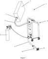
- Figure 1 shows an embodiment of the device 1 according to the invention, the device 1 comprising the following:
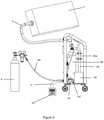
- FIG. 2 shows a detailed view of the preferred embodiment of the device, wherein CO 2 is provided from the tank into a reservoir 44 forming a part of the CO 2 distribution system.
- the CO 2 expands in the reservoir and can be then supplied to the chamber via the piping, valves and ventilator as described above. As said above, this enables that the CO 2 is at pressure 1 to 5 bar, which speeds up filling of the chamber.
- the CO 2 distribution system 4 has at least a first pipe 41 and a second pipe 42, connected to a ventilator 43, which is connected to the inlet/outlet pipe 3 with a pipe 45, which is preferably equipped with a filter 45a.
- the CO 2 is led out through the first pipe 41 to the outlet pipe 5 into the exterior of the building.
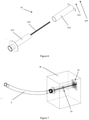
- Figure 3a shows a possible embodiment of the CO 2 distribution system comprising a housing where two pipes 41,42 are installed, each pipe having its own valve 41a, 42a, and both pipes connected to the ventilator 43, which is then connected to the inlet/outlet pipe 3 and consequently the chamber 2.
- Figure 3b shows the preferred embodiment of the CO 2 distribution system comprising a housing where the following components are installed:
- valves may be any suitable valves such as electromagnetic or mechanical valves, wherein the gate valve has to be present in case the chamber is designed as a flexible wrap.
- the gate valve 7 for connecting the inlet/outlet pipe 3 to the chamber 2 is shown in figure 4 and it comprises:
- FIG. 6 and 7 show the telescopic intra-wall part 51 and its installation into the wall W.
- the telescopic part 51 comprises:
- the wall has to be equipped with a pre-prepared hole having a diameter between 10 mm to 100m, into which the telescopic part 51 is installed.
- the smaller inner part 511 can move along the outer part 512, wherein a threaded pole 511' runs through the entire length of the telescopic part 51.
- a second nut is provided for tightening.
- the telescopic part can be adjusted so that it corresponds to the thickness of the wall W into which it is to be installed.
- the outlet 52 can be performed in any suitable way. Air can travel through the telescopic part into the interior of the CO 2 distribution system, more precisely towards the first pipe 41, or can travel to the exterior of the building when the therapy is over.
Landscapes
- Health & Medical Sciences (AREA)
- Public Health (AREA)
- Life Sciences & Earth Sciences (AREA)
- Veterinary Medicine (AREA)
- General Health & Medical Sciences (AREA)
- Animal Behavior & Ethology (AREA)
- Pulmonology (AREA)
- Biomedical Technology (AREA)
- Hematology (AREA)
- Heart & Thoracic Surgery (AREA)
- Anesthesiology (AREA)
- Engineering & Computer Science (AREA)
- Emergency Medicine (AREA)
- Pain & Pain Management (AREA)
- Epidemiology (AREA)
- Physical Education & Sports Medicine (AREA)
- Rehabilitation Therapy (AREA)
- Accommodation For Nursing Or Treatment Tables (AREA)
- Media Introduction/Drainage Providing Device (AREA)
- Devices For Medical Bathing And Washing (AREA)
- Medicinal Preparation (AREA)
- Pharmaceuticals Containing Other Organic And Inorganic Compounds (AREA)
Priority Applications (13)
| Application Number | Priority Date | Filing Date | Title |
|---|---|---|---|
| HRP20220477TT HRP20220477T1 (hr) | 2019-12-24 | 2019-12-24 | Uređaj za transkutanu primjenu ugljičnog dioksida |
| RS20220304A RS63064B1 (sr) | 2019-12-24 | 2019-12-24 | Uređaj za transkutanu primenu ugljen dioksida |
| LTEP19219593.1T LT3842092T (lt) | 2019-12-24 | 2019-12-24 | Anglies dioksido taikymo per odą aparatas |
| DK19219593.1T DK3842092T3 (da) | 2019-12-24 | 2019-12-24 | Indretning til transkutan anvendelse af carbondioxid |
| EP19219593.1A EP3842092B1 (en) | 2019-12-24 | 2019-12-24 | A device for transcutaneous application of carbon dioxide |
| SM20220146T SMT202200146T1 (it) | 2019-12-24 | 2019-12-24 | Dispositivo per applicazione di transcutanea di biossido di carbonio |
| PL19219593T PL3842092T3 (pl) | 2019-12-24 | 2019-12-24 | Urządzenie do przezskórnego podawania dwutlenku węgla |
| HUE19219593A HUE058853T2 (hu) | 2019-12-24 | 2019-12-24 | Készülék szén-dioxid transzkután alkalmazására |
| SI201930193T SI3842092T1 (sl) | 2019-12-24 | 2019-12-24 | Naprava za transkutano aplikacijo ogljikovega dioksida |
| ES19219593T ES2908023T3 (es) | 2019-12-24 | 2019-12-24 | Dispositivo para la aplicación transcutánea de dióxido de carbono |
| US17/115,356 US20210186788A1 (en) | 2019-12-24 | 2020-12-08 | Device for transcutaneous application of carbon dioxide and a functioning method of the said device |
| CA3102579A CA3102579A1 (en) | 2019-12-24 | 2020-12-14 | A device for transcutaneous application of carbon dioxide and a functioning method of the said device |
| CY20221100293T CY1125125T1 (el) | 2019-12-24 | 2022-04-20 | Συσκευη για τη διαδερμικη εφαρμογη διοξειδιου του ανθρακα |
Applications Claiming Priority (1)
| Application Number | Priority Date | Filing Date | Title |
|---|---|---|---|
| EP19219593.1A EP3842092B1 (en) | 2019-12-24 | 2019-12-24 | A device for transcutaneous application of carbon dioxide |
Publications (2)
| Publication Number | Publication Date |
|---|---|
| EP3842092A1 EP3842092A1 (en) | 2021-06-30 |
| EP3842092B1 true EP3842092B1 (en) | 2022-01-26 |
Family
ID=69061146
Family Applications (1)
| Application Number | Title | Priority Date | Filing Date |
|---|---|---|---|
| EP19219593.1A Active EP3842092B1 (en) | 2019-12-24 | 2019-12-24 | A device for transcutaneous application of carbon dioxide |
Country Status (13)
| Country | Link |
|---|---|
| US (1) | US20210186788A1 (da) |
| EP (1) | EP3842092B1 (da) |
| CA (1) | CA3102579A1 (da) |
| CY (1) | CY1125125T1 (da) |
| DK (1) | DK3842092T3 (da) |
| ES (1) | ES2908023T3 (da) |
| HR (1) | HRP20220477T1 (da) |
| HU (1) | HUE058853T2 (da) |
| LT (1) | LT3842092T (da) |
| PL (1) | PL3842092T3 (da) |
| RS (1) | RS63064B1 (da) |
| SI (1) | SI3842092T1 (da) |
| SM (1) | SMT202200146T1 (da) |
Families Citing this family (1)
| Publication number | Priority date | Publication date | Assignee | Title |
|---|---|---|---|---|
| CN118881961B (zh) * | 2024-10-08 | 2024-12-13 | 南通天泽化工有限公司 | 一种化工车间液体材料泄漏应急处理装置 |
Family Cites Families (10)
| Publication number | Priority date | Publication date | Assignee | Title |
|---|---|---|---|---|
| US2366799A (en) * | 1943-03-23 | 1945-01-09 | Aldo A Luisada | Method of and means for treating heart ailments |
| US4772259A (en) * | 1987-06-12 | 1988-09-20 | Ballard Medical Products | Hyperbaric oxygenation apparatus and methods |
| US5425742A (en) * | 1994-03-28 | 1995-06-20 | Patrick S. Quigley | Use of hollow hypobaric chambers on body parts for increasing blood flow, reducing pressure and decreasing pain |
| GB9523253D0 (en) * | 1995-11-14 | 1996-01-17 | Mediscus Prod Ltd | Portable wound treatment apparatus |
| DE20307743U1 (de) * | 2002-05-24 | 2003-09-25 | Kovarik, Robert, Dr., 52074 Aachen | Vorrichtung für die nicht medizinische CO2-Gasbehandlung von Personen |
| US7998125B2 (en) * | 2004-05-21 | 2011-08-16 | Bluesky Medical Group Incorporated | Hypobaric chamber treatment system |
| US20110040239A1 (en) * | 2009-08-11 | 2011-02-17 | Hans-Georg Schneider | Apparatus for the production of ionized oxygen and ozone from pure oxygen and methods for using same in medical applications |
| WO2012086636A1 (ja) * | 2010-12-20 | 2012-06-28 | アドバンス・バイオトロン株式会社 | 生体の虚血領域の血行状態を改善又は促進するための炭酸ガスミスト圧浴方法及び炭酸ガスミスト圧浴装置 |
| US9480830B1 (en) * | 2013-04-16 | 2016-11-01 | Jose Azocar | Assembly for tissue oxygenation and method of use |
| SG11201908087TA (en) * | 2017-01-31 | 2019-10-30 | Berta Zsolt Zoltan | Apparatus for transcutaneous treatment by gas |
-
2019
- 2019-12-24 DK DK19219593.1T patent/DK3842092T3/da active
- 2019-12-24 RS RS20220304A patent/RS63064B1/sr unknown
- 2019-12-24 SI SI201930193T patent/SI3842092T1/sl unknown
- 2019-12-24 PL PL19219593T patent/PL3842092T3/pl unknown
- 2019-12-24 ES ES19219593T patent/ES2908023T3/es active Active
- 2019-12-24 HU HUE19219593A patent/HUE058853T2/hu unknown
- 2019-12-24 LT LTEP19219593.1T patent/LT3842092T/lt unknown
- 2019-12-24 SM SM20220146T patent/SMT202200146T1/it unknown
- 2019-12-24 EP EP19219593.1A patent/EP3842092B1/en active Active
- 2019-12-24 HR HRP20220477TT patent/HRP20220477T1/hr unknown
-
2020
- 2020-12-08 US US17/115,356 patent/US20210186788A1/en not_active Abandoned
- 2020-12-14 CA CA3102579A patent/CA3102579A1/en active Pending
-
2022
- 2022-04-20 CY CY20221100293T patent/CY1125125T1/el unknown
Also Published As
| Publication number | Publication date |
|---|---|
| HUE058853T2 (hu) | 2022-09-28 |
| SMT202200146T1 (it) | 2022-05-12 |
| SI3842092T1 (sl) | 2022-05-31 |
| HRP20220477T1 (hr) | 2022-05-27 |
| EP3842092A1 (en) | 2021-06-30 |
| RS63064B1 (sr) | 2022-04-29 |
| CY1125125T1 (el) | 2024-12-13 |
| CA3102579A1 (en) | 2021-06-24 |
| ES2908023T3 (es) | 2022-04-27 |
| LT3842092T (lt) | 2022-04-25 |
| US20210186788A1 (en) | 2021-06-24 |
| PL3842092T3 (pl) | 2022-05-16 |
| DK3842092T3 (da) | 2022-02-21 |
Similar Documents
| Publication | Publication Date | Title |
|---|---|---|
| US11090475B2 (en) | Medical treatment system and method of use | |
| CA2696313C (en) | Drug delivery system | |
| JP5875192B2 (ja) | 陽陰圧換気システムおよび胸腔内圧調整方法 | |
| WO2008130689A1 (en) | Device and method for treating chronic wounds | |
| EP2905008B2 (en) | Apparatus for the treatment of wounds with oxygen | |
| US20120065576A1 (en) | Drug delivery system | |
| EP3842092B1 (en) | A device for transcutaneous application of carbon dioxide | |
| CN105919780A (zh) | 肢端血液循环障碍治疗机 | |
| US5443447A (en) | Intracavitary delivery or withdrawal device | |
| KR20130128309A (ko) | 심근 경색을 예방, 개선 또는 치료하기 위한 탄산 가스 미스트 압욕 방법 및 탄산 가스 미스트 압욕 장치 | |
| RU2825696C2 (ru) | Устройство для чрескожного применения диоксида углерода и способ функционирования указанного устройства | |
| CN107432974A (zh) | 一种无痛自动麻醉装置 | |
| WO2012086636A1 (ja) | 生体の虚血領域の血行状態を改善又は促進するための炭酸ガスミスト圧浴方法及び炭酸ガスミスト圧浴装置 | |
| CN206950426U (zh) | 一种适用于不同人群的医用雾化器 | |
| CN109529177A (zh) | 一种将治疗药剂传递至特定治疗位点的装置 | |
| CN223299376U (zh) | 一种胸腔用减痛引流管 | |
| CN208492943U (zh) | 带涂层的螺纹导尿管 | |
| CN106823077A (zh) | 一种适用于不同人群的医用雾化器 | |
| RU84700U1 (ru) | Комплекс интенсивной терапии системы гипербарической оксигенации | |
| Klinzing et al. | One-lung flooding for video-assisted thoracoscopic surgery in animal experiments on pigs—oxygenation and intrapulmonary shunt | |
| CN221713218U (zh) | 一种呼吸机管路雾化连接器 | |
| WO2006000006A2 (de) | Einrichtung zum kühlen eines patienten und einrichtung zur abgabe der kälte an einen patienten | |
| EP1518524A1 (de) | Verfahren und Vorrichtung zur äusserlichen Fluid-Behandlung eines menschlichen und/oder tierischen Körpers | |
| CN110353980A (zh) | 一种呼吸内科鼻腔喷雾清洁装置 | |
| DE2830596A1 (de) | Selbstabdichtendes, durch die haut zu punktierendes katheterendstueck zur langzeitinfusion von medikamenten in organarterien |
Legal Events
| Date | Code | Title | Description |
|---|---|---|---|
| REG | Reference to a national code |
Ref country code: HR Ref legal event code: TUEP Ref document number: P20220477 Country of ref document: HR |
|
| PUAI | Public reference made under article 153(3) epc to a published international application that has entered the european phase |
Free format text: ORIGINAL CODE: 0009012 |
|
| STAA | Information on the status of an ep patent application or granted ep patent |
Free format text: STATUS: THE APPLICATION HAS BEEN PUBLISHED |
|
| AK | Designated contracting states |
Kind code of ref document: A1 Designated state(s): AL AT BE BG CH CY CZ DE DK EE ES FI FR GB GR HR HU IE IS IT LI LT LU LV MC MK MT NL NO PL PT RO RS SE SI SK SM TR |
|
| STAA | Information on the status of an ep patent application or granted ep patent |
Free format text: STATUS: REQUEST FOR EXAMINATION WAS MADE |
|
| 17P | Request for examination filed |
Effective date: 20210922 |
|
| RBV | Designated contracting states (corrected) |
Designated state(s): AL AT BE BG CH CY CZ DE DK EE ES FI FR GB GR HR HU IE IS IT LI LT LU LV MC MK MT NL NO PL PT RO RS SE SI SK SM TR |
|
| GRAP | Despatch of communication of intention to grant a patent |
Free format text: ORIGINAL CODE: EPIDOSNIGR1 |
|
| STAA | Information on the status of an ep patent application or granted ep patent |
Free format text: STATUS: GRANT OF PATENT IS INTENDED |
|
| RIC1 | Information provided on ipc code assigned before grant |
Ipc: A61H 35/00 20060101ALI20211104BHEP Ipc: A61H 33/14 20060101ALI20211104BHEP Ipc: A61M 35/00 20060101AFI20211104BHEP |
|
| GRAS | Grant fee paid |
Free format text: ORIGINAL CODE: EPIDOSNIGR3 |
|
| GRAA | (expected) grant |
Free format text: ORIGINAL CODE: 0009210 |
|
| STAA | Information on the status of an ep patent application or granted ep patent |
Free format text: STATUS: THE PATENT HAS BEEN GRANTED |
|
| INTG | Intention to grant announced |
Effective date: 20211129 |
|
| AK | Designated contracting states |
Kind code of ref document: B1 Designated state(s): AL AT BE BG CH CY CZ DE DK EE ES FI FR GB GR HR HU IE IS IT LI LT LU LV MC MK MT NL NO PL PT RO RS SE SI SK SM TR |
|
| REG | Reference to a national code |
Ref country code: GB Ref legal event code: FG4D |
|
| REG | Reference to a national code |
Ref country code: CH Ref legal event code: EP |
|
| REG | Reference to a national code |
Ref country code: AT Ref legal event code: REF Ref document number: 1464790 Country of ref document: AT Kind code of ref document: T Effective date: 20220215 |
|
| REG | Reference to a national code |
Ref country code: IE Ref legal event code: FG4D |
|
| REG | Reference to a national code |
Ref country code: DE Ref legal event code: R096 Ref document number: 602019011225 Country of ref document: DE |
|
| REG | Reference to a national code |
Ref country code: DK Ref legal event code: T3 Effective date: 20220215 |
|
| REG | Reference to a national code |
Ref country code: FI Ref legal event code: FGE |
|
| REG | Reference to a national code |
Ref country code: SE Ref legal event code: TRGR |
|
| REG | Reference to a national code |
Ref country code: RO Ref legal event code: EPE |
|
| REG | Reference to a national code |
Ref country code: EE Ref legal event code: FG4A Ref document number: E021999 Country of ref document: EE Effective date: 20220221 |
|
| REG | Reference to a national code |
Ref country code: ES Ref legal event code: FG2A Ref document number: 2908023 Country of ref document: ES Kind code of ref document: T3 Effective date: 20220427 |
|
| REG | Reference to a national code |
Ref country code: NL Ref legal event code: FP |
|
| REG | Reference to a national code |
Ref country code: HR Ref legal event code: T1PR Ref document number: P20220477 Country of ref document: HR |
|
| REG | Reference to a national code |
Ref country code: GR Ref legal event code: EP Ref document number: 20220400814 Country of ref document: GR Effective date: 20220509 |
|
| REG | Reference to a national code |
Ref country code: NO Ref legal event code: T2 Effective date: 20220126 |
|
| REG | Reference to a national code |
Ref country code: HU Ref legal event code: AG4A Ref document number: E058853 Country of ref document: HU |
|
| REG | Reference to a national code |
Ref country code: DE Ref legal event code: R097 Ref document number: 602019011225 Country of ref document: DE |
|
| PLBE | No opposition filed within time limit |
Free format text: ORIGINAL CODE: 0009261 |
|
| STAA | Information on the status of an ep patent application or granted ep patent |
Free format text: STATUS: NO OPPOSITION FILED WITHIN TIME LIMIT |
|
| 26N | No opposition filed |
Effective date: 20221027 |
|
| REG | Reference to a national code |
Ref country code: HR Ref legal event code: ODRP Ref document number: P20220477 Country of ref document: HR Payment date: 20221216 Year of fee payment: 4 |
|
| REG | Reference to a national code |
Ref country code: AT Ref legal event code: UEP Ref document number: 1464790 Country of ref document: AT Kind code of ref document: T Effective date: 20220126 |
|
| PG25 | Lapsed in a contracting state [announced via postgrant information from national office to epo] |
Ref country code: RO Free format text: LAPSE BECAUSE OF NON-PAYMENT OF DUE FEES Effective date: 20220126 |
|
| REG | Reference to a national code |
Ref country code: HR Ref legal event code: ODRP Ref document number: P20220477 Country of ref document: HR Payment date: 20231221 Year of fee payment: 5 |
|
| PG25 | Lapsed in a contracting state [announced via postgrant information from national office to epo] |
Ref country code: MT Free format text: LAPSE BECAUSE OF FAILURE TO SUBMIT A TRANSLATION OF THE DESCRIPTION OR TO PAY THE FEE WITHIN THE PRESCRIBED TIME-LIMIT Effective date: 20220126 |
|
| REG | Reference to a national code |
Ref country code: HR Ref legal event code: ODRP Ref document number: P20220477 Country of ref document: HR Payment date: 20241216 Year of fee payment: 6 |
|
| PGFP | Annual fee paid to national office [announced via postgrant information from national office to epo] |
Ref country code: HU Payment date: 20241217 Year of fee payment: 6 |
|
| PGFP | Annual fee paid to national office [announced via postgrant information from national office to epo] |
Ref country code: DE Payment date: 20241223 Year of fee payment: 6 |
|
| PGFP | Annual fee paid to national office [announced via postgrant information from national office to epo] |
Ref country code: ES Payment date: 20250102 Year of fee payment: 6 |
|
| PGFP | Annual fee paid to national office [announced via postgrant information from national office to epo] |
Ref country code: CH Payment date: 20250101 Year of fee payment: 6 |
|
| PGFP | Annual fee paid to national office [announced via postgrant information from national office to epo] |
Ref country code: CY Payment date: 20241220 Year of fee payment: 6 |
|
| REG | Reference to a national code |
Ref country code: CH Ref legal event code: U11 Free format text: ST27 STATUS EVENT CODE: U-0-0-U10-U11 (AS PROVIDED BY THE NATIONAL OFFICE) Effective date: 20260101 |
|
| PGFP | Annual fee paid to national office [announced via postgrant information from national office to epo] |
Ref country code: IS Payment date: 20251215 Year of fee payment: 7 |
|
| PGFP | Annual fee paid to national office [announced via postgrant information from national office to epo] |
Ref country code: LT Payment date: 20251212 Year of fee payment: 7 Ref country code: GB Payment date: 20251216 Year of fee payment: 7 |
|
| PGFP | Annual fee paid to national office [announced via postgrant information from national office to epo] |
Ref country code: NO Payment date: 20251211 Year of fee payment: 7 Ref country code: MC Payment date: 20251218 Year of fee payment: 7 |
|
| PGFP | Annual fee paid to national office [announced via postgrant information from national office to epo] |
Ref country code: AT Payment date: 20251231 Year of fee payment: 7 Ref country code: SM Payment date: 20251216 Year of fee payment: 7 Ref country code: MK Payment date: 20251212 Year of fee payment: 7 Ref country code: PT Payment date: 20251211 Year of fee payment: 7 |
|
| PGFP | Annual fee paid to national office [announced via postgrant information from national office to epo] |
Ref country code: IT Payment date: 20251212 Year of fee payment: 7 Ref country code: FI Payment date: 20251223 Year of fee payment: 7 Ref country code: DK Payment date: 20251222 Year of fee payment: 7 |
|
| PGFP | Annual fee paid to national office [announced via postgrant information from national office to epo] |
Ref country code: LU Payment date: 20251211 Year of fee payment: 7 Ref country code: HR Payment date: 20251209 Year of fee payment: 7 Ref country code: FR Payment date: 20251222 Year of fee payment: 7 Ref country code: NL Payment date: 20251226 Year of fee payment: 7 |
|
| PGFP | Annual fee paid to national office [announced via postgrant information from national office to epo] |
Ref country code: TR Payment date: 20251216 Year of fee payment: 7 Ref country code: AL Payment date: 20251215 Year of fee payment: 7 Ref country code: GR Payment date: 20251231 Year of fee payment: 7 Ref country code: BE Payment date: 20251215 Year of fee payment: 7 |
|
| REG | Reference to a national code |
Ref country code: HR Ref legal event code: ODRP Ref document number: P20220477 Country of ref document: HR Payment date: 20251209 Year of fee payment: 7 |
|
| PGFP | Annual fee paid to national office [announced via postgrant information from national office to epo] |
Ref country code: SE Payment date: 20251217 Year of fee payment: 7 |
|
| PGFP | Annual fee paid to national office [announced via postgrant information from national office to epo] |
Ref country code: IE Payment date: 20251211 Year of fee payment: 7 Ref country code: CZ Payment date: 20251217 Year of fee payment: 7 |
|
| PGFP | Annual fee paid to national office [announced via postgrant information from national office to epo] |
Ref country code: LV Payment date: 20251212 Year of fee payment: 7 |
|
| PGFP | Annual fee paid to national office [announced via postgrant information from national office to epo] |
Ref country code: BG Payment date: 20251211 Year of fee payment: 7 Ref country code: PL Payment date: 20251208 Year of fee payment: 7 |
|
| PGFP | Annual fee paid to national office [announced via postgrant information from national office to epo] |
Ref country code: EE Payment date: 20251220 Year of fee payment: 7 |
|
| PGFP | Annual fee paid to national office [announced via postgrant information from national office to epo] |
Ref country code: SK Payment date: 20251212 Year of fee payment: 7 Ref country code: RO Payment date: 20251208 Year of fee payment: 7 |
|
| PGFP | Annual fee paid to national office [announced via postgrant information from national office to epo] |
Ref country code: RS Payment date: 20251216 Year of fee payment: 7 |
|
| PGFP | Annual fee paid to national office [announced via postgrant information from national office to epo] |
Ref country code: SI Payment date: 20251205 Year of fee payment: 7 |