EP3841999B1 - Combined cardiac pacing and irreversible electroporation (ire) treatment - Google Patents
Combined cardiac pacing and irreversible electroporation (ire) treatment Download PDFInfo
- Publication number
- EP3841999B1 EP3841999B1 EP20216796.1A EP20216796A EP3841999B1 EP 3841999 B1 EP3841999 B1 EP 3841999B1 EP 20216796 A EP20216796 A EP 20216796A EP 3841999 B1 EP3841999 B1 EP 3841999B1
- Authority
- EP
- European Patent Office
- Prior art keywords
- ire
- pacing
- pulses
- cardiac
- treatment
- Prior art date
- Legal status (The legal status is an assumption and is not a legal conclusion. Google has not performed a legal analysis and makes no representation as to the accuracy of the status listed.)
- Active
Links
- 230000000747 cardiac effect Effects 0.000 title claims description 20
- 238000004520 electroporation Methods 0.000 title claims description 9
- 230000002427 irreversible effect Effects 0.000 title claims description 8
- 239000000523 sample Substances 0.000 claims description 15
- 210000005003 heart tissue Anatomy 0.000 claims description 8
- 238000007493 shaping process Methods 0.000 claims description 7
- 238000000034 method Methods 0.000 description 23
- 210000001519 tissue Anatomy 0.000 description 12
- 206010003119 arrhythmia Diseases 0.000 description 8
- 230000006793 arrhythmia Effects 0.000 description 7
- 238000002679 ablation Methods 0.000 description 5
- 230000003126 arrythmogenic effect Effects 0.000 description 5
- 230000002051 biphasic effect Effects 0.000 description 3
- 238000013507 mapping Methods 0.000 description 3
- 230000000638 stimulation Effects 0.000 description 3
- 238000010317 ablation therapy Methods 0.000 description 2
- 239000003990 capacitor Substances 0.000 description 2
- 238000003745 diagnosis Methods 0.000 description 2
- 238000010586 diagram Methods 0.000 description 2
- 230000000694 effects Effects 0.000 description 2
- 230000006870 function Effects 0.000 description 2
- 238000003780 insertion Methods 0.000 description 2
- 230000037431 insertion Effects 0.000 description 2
- 238000002955 isolation Methods 0.000 description 2
- 238000012545 processing Methods 0.000 description 2
- 229930186657 Lat Natural products 0.000 description 1
- 230000004913 activation Effects 0.000 description 1
- 230000001419 dependent effect Effects 0.000 description 1
- 238000002405 diagnostic procedure Methods 0.000 description 1
- 239000003814 drug Substances 0.000 description 1
- 229940079593 drug Drugs 0.000 description 1
- 230000005684 electric field Effects 0.000 description 1
- 230000002169 extracardiac Effects 0.000 description 1
- 238000002847 impedance measurement Methods 0.000 description 1
- 238000005259 measurement Methods 0.000 description 1
- 239000000203 mixture Substances 0.000 description 1
- 238000012986 modification Methods 0.000 description 1
- 230000004048 modification Effects 0.000 description 1
- 230000003287 optical effect Effects 0.000 description 1
- 230000037361 pathway Effects 0.000 description 1
- 230000008569 process Effects 0.000 description 1
- 230000000644 propagated effect Effects 0.000 description 1
- 210000003492 pulmonary vein Anatomy 0.000 description 1
- 238000000718 qrs complex Methods 0.000 description 1
- 230000036279 refractory period Effects 0.000 description 1
- 230000033764 rhythmic process Effects 0.000 description 1
- 238000012163 sequencing technique Methods 0.000 description 1
- 230000000007 visual effect Effects 0.000 description 1
Images
Classifications
-
- A—HUMAN NECESSITIES
- A61—MEDICAL OR VETERINARY SCIENCE; HYGIENE
- A61B—DIAGNOSIS; SURGERY; IDENTIFICATION
- A61B18/00—Surgical instruments, devices or methods for transferring non-mechanical forms of energy to or from the body
- A61B18/04—Surgical instruments, devices or methods for transferring non-mechanical forms of energy to or from the body by heating
- A61B18/12—Surgical instruments, devices or methods for transferring non-mechanical forms of energy to or from the body by heating by passing a current through the tissue to be heated, e.g. high-frequency current
- A61B18/1206—Generators therefor
- A61B18/1233—Generators therefor with circuits for assuring patient safety
-
- A—HUMAN NECESSITIES
- A61—MEDICAL OR VETERINARY SCIENCE; HYGIENE
- A61B—DIAGNOSIS; SURGERY; IDENTIFICATION
- A61B18/00—Surgical instruments, devices or methods for transferring non-mechanical forms of energy to or from the body
- A61B18/04—Surgical instruments, devices or methods for transferring non-mechanical forms of energy to or from the body by heating
- A61B18/12—Surgical instruments, devices or methods for transferring non-mechanical forms of energy to or from the body by heating by passing a current through the tissue to be heated, e.g. high-frequency current
- A61B18/14—Probes or electrodes therefor
- A61B18/1492—Probes or electrodes therefor having a flexible, catheter-like structure, e.g. for heart ablation
-
- A—HUMAN NECESSITIES
- A61—MEDICAL OR VETERINARY SCIENCE; HYGIENE
- A61B—DIAGNOSIS; SURGERY; IDENTIFICATION
- A61B18/00—Surgical instruments, devices or methods for transferring non-mechanical forms of energy to or from the body
- A61B18/04—Surgical instruments, devices or methods for transferring non-mechanical forms of energy to or from the body by heating
- A61B18/12—Surgical instruments, devices or methods for transferring non-mechanical forms of energy to or from the body by heating by passing a current through the tissue to be heated, e.g. high-frequency current
-
- A—HUMAN NECESSITIES
- A61—MEDICAL OR VETERINARY SCIENCE; HYGIENE
- A61N—ELECTROTHERAPY; MAGNETOTHERAPY; RADIATION THERAPY; ULTRASOUND THERAPY
- A61N1/00—Electrotherapy; Circuits therefor
- A61N1/18—Applying electric currents by contact electrodes
- A61N1/32—Applying electric currents by contact electrodes alternating or intermittent currents
- A61N1/327—Applying electric currents by contact electrodes alternating or intermittent currents for enhancing the absorption properties of tissue, e.g. by electroporation
-
- A—HUMAN NECESSITIES
- A61—MEDICAL OR VETERINARY SCIENCE; HYGIENE
- A61B—DIAGNOSIS; SURGERY; IDENTIFICATION
- A61B18/00—Surgical instruments, devices or methods for transferring non-mechanical forms of energy to or from the body
- A61B2018/00315—Surgical instruments, devices or methods for transferring non-mechanical forms of energy to or from the body for treatment of particular body parts
- A61B2018/00345—Vascular system
- A61B2018/00351—Heart
-
- A—HUMAN NECESSITIES
- A61—MEDICAL OR VETERINARY SCIENCE; HYGIENE
- A61B—DIAGNOSIS; SURGERY; IDENTIFICATION
- A61B18/00—Surgical instruments, devices or methods for transferring non-mechanical forms of energy to or from the body
- A61B2018/00571—Surgical instruments, devices or methods for transferring non-mechanical forms of energy to or from the body for achieving a particular surgical effect
- A61B2018/00577—Ablation
-
- A—HUMAN NECESSITIES
- A61—MEDICAL OR VETERINARY SCIENCE; HYGIENE
- A61B—DIAGNOSIS; SURGERY; IDENTIFICATION
- A61B18/00—Surgical instruments, devices or methods for transferring non-mechanical forms of energy to or from the body
- A61B2018/00571—Surgical instruments, devices or methods for transferring non-mechanical forms of energy to or from the body for achieving a particular surgical effect
- A61B2018/00613—Irreversible electroporation
-
- A—HUMAN NECESSITIES
- A61—MEDICAL OR VETERINARY SCIENCE; HYGIENE
- A61B—DIAGNOSIS; SURGERY; IDENTIFICATION
- A61B18/00—Surgical instruments, devices or methods for transferring non-mechanical forms of energy to or from the body
- A61B2018/00636—Sensing and controlling the application of energy
- A61B2018/00696—Controlled or regulated parameters
- A61B2018/00702—Power or energy
-
- A—HUMAN NECESSITIES
- A61—MEDICAL OR VETERINARY SCIENCE; HYGIENE
- A61B—DIAGNOSIS; SURGERY; IDENTIFICATION
- A61B18/00—Surgical instruments, devices or methods for transferring non-mechanical forms of energy to or from the body
- A61B2018/00636—Sensing and controlling the application of energy
- A61B2018/00696—Controlled or regulated parameters
- A61B2018/00732—Frequency
Definitions
- the present invention relates generally to electroanatomical mapping combined with ablation, and particularly to cardiac pacing and irreversible electroporation (IRE).
- IRE irreversible electroporation
- U.S. Patent No. 9,987,081 describes systems, devices, and methods for electroporation ablation therapy, with the system including a pulse waveform signal generator for medical ablation therapy that may be coupled to an ablation device including at least one electrode for ablation pulse delivery to tissue.
- the signal generator may generate and deliver voltage pulses to the ablation device in the form of a pulse waveform in a predetermined sequence.
- the system may include a cardiac stimulator configured to generate a pacing signal for cardiac stimulation during use.
- the cardiac stimulator may be communicably coupled to the signal generator and further configured to transmit an indication of the pacing signal to the signal generator.
- the processor of the signal generator may be further configured to generate the pulse waveform in synchronization with the indication of the pacing signal, where the synchronization may include a predetermined offset.
- a method of treatment may include electrically pacing the heart with a cardiac stimulator to ensure pacing capture to establish periodicity and predictability of the cardiac cycle, and then defining a time window within the refractory period of the cardiac cycle within which one or more pulsed ablation waveforms may be delivered.
- U.S. Patent Application Publication 2018/0042674 describes a method including selecting a sub-set of electrode pairs of a multi-electrode catheter, the multi-electrode catheter configured to be disposed about a portion of a heart.
- a pacing signal is conveyed to a pacing lead configured to be operatively coupled to the heart.
- An electrocardiograph signal associated with a function of the heart is received at a feedback module of the electrode controller.
- a pulsed voltage waveform is delivered to the sub-set of electrode pairs according to a sequential pattern, the pulsed voltage waveform including a pre-polarizing pulse followed by a polarizing pulse, the pre-polarizing pulse being generated by utilizing voltage spikes generated from switching on a discharge of a capacitor bank.
- WO2017024123A1 there is described a method for ablating tissue by applying at least one pulse train of pulsed-field energy.
- WO9518649A1 there is described an apparatus and method for delivering a drug selectively and locally to internal body tissue with a catheter using electric current/voltage controlled in conjunction with active pacing of cardiac activity.
- Cardiac arrhythmia which is defined as a variation from the normal heart sinus rhythm, may originate in, or be conducted by, different portions of cardiac tissue, named hereinafter "arrhythmogenic locations.”
- arrhythmogenic locations One possible method to search for an arrhythmogenic location is to electrically stimulate selected locations on the cardiac tissue surface of a patient using bipolar electrical signals. Such stimulation, which may be done using an electrode pair on a catheter, may induce an electrocardiogram (ECG) signal pattern that meets one or more criteria to identify a stimulated location as an arrhythmogenic focus or pathway.
- ECG electrocardiogram
- a treatment of the identified arrhythmogenic location is done, for example, by irreversibly electroporating (IRE) the location, which generates a high electric field that kills targeted tissue cells, which is likely to reduce or eliminate the arrhythmia in question.
- IRE irreversibly electroporating
- it may be hard to pace and subsequently apply IRE treatment at the same location exactly, in part due to cardiac motion.
- two different sets of driving electronics e.g., generators
- Exemplary embodiments of the present invention that are described hereinafter provide a combined technique to perform substantially simultaneously and/or sequentially diagnostic pacing and IRE treatment of arrhythmia at a given cardiac tissue location using combined generation and application of cardiac pacing pulses and of IRE pulses. While the high-voltage requirements for IRE may be in the range of kilovolts, the power requirements for IRE are small, in a range of a few tens of milliwatts. Thus, much of the circuitry for both the IRE pulse generation and for the pacing may be the same, the only differences being the pulse sequencing and amplitude.
- a cardiac pacing and IRE treatment apparatus which comprises a pulse generator and a shaping circuit.
- the pulse generator is configured to generate IRE pulses of a prespecified shape and repetition rate.
- the shaping circuit is configured to convert some of the IRE pulses into pacing pulses of a prespecified frequency and amplitude, to generate an output signal comprising ones of the IRE pulses interleaved with ones of the pacing pulses, and to output the output signal to a probe in a heart of a patient for applying the output signal to cardiac tissue.
- a processor my vary the output waveform to apply only pacing pulses, only IRE pulses, or M IRE pacing pulses and N IRE pulses RFA interleaved with M ⁇ 1, N ⁇ 1.
- the catheter is configured for insertion into a heart of a patient and applying the output signal to heart tissue.
- IRE pulse shape and repetition rate controls the generator
- pacing parameters such as pacing frequency.
- the generator is able to generate biphasic pulses with peak to peak voltage of up to 4 kV, and at typical pulse-widths on the order of pSec.
- the generator is able to generate pulses with peak voltage of up to few volts at a range of a few hundred cycles per minute.
- the processor is programmed in software containing a particular algorithm that enables the processor to conduct each of the processor-related steps and functions outlined above.
- the disclosed combined pacing and IRE technique may improve the clinical outcome of an invasive treatment of arrhythmia while at the same time decrease the work load experienced by the physician performing the procedure.
- Fig. 1 is a schematic, pictorial illustration of a combined cardiac pacing and irreversible electroporation (IRE) system 20, in accordance with an exemplary embodiment of the present invention.
- System 20 may be configured to stimulate and analyze substantially any electrophysiological (EP) parameter or combination of such parameters.
- a console 46 of system 20 comprises a combined pacing/IRE pulse generator 33 that generates and applies interweaved pacing/IRE waveforms via a probe 24 to cardiac tissue in a heart 34 of a patient 26.
- the signals analyzed are assumed to be intra-cardiac and/or extra-cardiac (body surface) ECG potential-time relationships.
- the signals at various locations need to be referenced in time to each other, such as is done, for example, while generating a local activation time (LAT) map.
- the time referencing is accomplished by measurements done relative to a reference time (e.g., instance), such as the beginning of each QRS complex of an ECG reference signal (i.e., the beginning of every heartbeat).
- a reference time e.g., instance
- a method for generating an LAT map is described in U.S Patent No. 9,050,011 , cited above.
- system 20 stimulates (i.e., paces) heart 34 using a pacing and IRE probe 24.
- System 20 measures resulting electrical activity of a heart 34, using probe 24 itself and/or using an additional probe 14.
- a distal end 32 of probe 24 is assumed to have electrodes 22.
- the measured signals are used for, among other usages, creating an LAT map of at least a portion of the wall tissue of heart 34.
- probe 24 comprises a mapping catheter which is inserted into the body of patient 26 during a mapping procedure performed by a physician 28 using system 20.
- the procedure embodied in Fig. 1 uses an M1-M2 bipolar electrode pair configuration of probe 24 for pacing (i.e., for EP stimulation) and for IRE treatment of the tissue site found as arrhythmogenic using combined pacing and IRE pulse generator 33.
- the catheter is further configured to acquire intracardiac electrophysiological signals.
- patient 26 is assumed to be attached to a grounding electrode (i.e., ground patch) 23.
- electrodes 29 are assumed to be attached to the skin of patient 26, in the region of heart 34.
- System 20 is controlled by a system processor 40, comprising a processing unit 42 communicating with a memory 44.
- memory 44 which is included in system processor 40, stores an EP map 62 of at least a portion of wall tissue of heart 34 of patient 26.
- Processor 40 is typically mounted in console 46, which comprises (a) a patient interface unit 43 to which all the catheters connect, and (b) a workstation having operating controls 38, typically including a pointing device 39 such as a mouse or trackball used by physician 28 to interact with the processor.
- Processor 40 (specifically processing unit 42) runs software comprising a probe tracker module 30, an ECG module 36 comprising an arrhythmia analysis module, and a graphical user interface (GUI) 35, to operate system 20 and/or to graphically analyze and present results (using EP map 62 stored in memory 44) from the disclosed heart pacing and IRE treatment workflow described in Fig. 3 so as, for example, to identify sources of an arrhythmia and to treat them with IRE.
- software comprising a probe tracker module 30, an ECG module 36 comprising an arrhythmia analysis module, and a graphical user interface (GUI) 35, to operate system 20 and/or to graphically analyze and present results (using EP map 62 stored in memory 44) from the disclosed heart pacing and IRE treatment workflow described in Fig. 3 so as, for example, to identify sources of an arrhythmia and to treat them with IRE.
- GUI graphical user interface
- ECG module 36 is coupled to receive electrical signals from electrodes 22 and electrodes 29.
- the module is configured to analyze the electrical signals and may present the results of the analysis in a standard ECG format, typically a graphical representation moving with time, on display 48.
- Probe tracker module 30 typically tracks the location of distal end 32 of probe 24 within the heart of patient 26.
- the tracker module may use any method for probe location tracking known in the art.
- module 30 may operate a magnetic-field based location tracking sub-system. (For simplicity, components of such sub-system are not shown in Fig. 1 .)
- tracker module 30 may track probe 24 by measuring impedances between electrode 23 and electrodes 22, as well as the impedances to other electrodes which may be located on the probe.
- electrodes 22 may provide both ECG and location tracking signals.
- the Carto3 ® system produced by Biosense-Webster (Irvine, California) uses both magnetic field location tracking and impedance measurements for location tracking.
- processor 40 is able to measure locations of distal end 32.
- the processor is able to measure locations of the distal end, as well as LATs of electrical signals detected at these particular locations.
- Results of the operations performed by processor 40 are presented to physician 28 on a display 48, which typically presents a graphic user interface to the physician, a visual representation of the ECG signals sensed by electrodes 22, and/or an image or map of heart 34 while it is being investigated.
- GUI 35 presents to the physician an EP map updated with one or more locations on the map where an identified arrhythmia originated or through which it propagated.
- the software may be downloaded to processor 40 in electronic form, over a network, for example, or it may, alternatively or additionally, be provided and/or stored on non-transitory tangible media, such as magnetic, optical, or electronic memory.
- Fig. 2 is a schematic block diagram of the combined pacing and IRE pulse generator 33 of the system of Fig. 1 , in accordance with an exemplary embodiment of the present invention.
- generator 33 comprises an IRE pulse generator 50 and a pacing/IRE waveform shaper and interleaver 55, which are both configurable and controlled by processor 40.
- IRE pulse generator 50 generates a sequence 52 of high-voltage biphasic pulses of a predefined waveform for IRE.
- Pacing/IRE waveform shaper and pulse interleaver 55 comprises pulse shaper circuitry and waveform interleaving circuitry.
- the biphasic pulse shaper circuitry is configured to modify IRE pulses of sequence 52 to a shape and repetition rate required of pacing pulses.
- generator 33 includes electrical elements, such as a reinforced isolated amplifier, to convert the waveform voltage from the high-voltage domain of IRE pulses into a low-voltage domain of pacing pulses.
- the pulse shaper may include an array of capacitors that may produce a different rise time and fall time of the pulses.
- the waveform interleaver comprises a switching circuitry to switch between IRE input and pacing pulses delivered to catheter 24.
- exemplary configurations illustrated in the Fig. 2 is chosen purely for the sake of conceptual clarity.
- the disclosed techniques may use any other suitable pulse generation and shaping scheme.
- Fig. 3 is a flow chart that schematically illustrates a method of combined cardiac pacing and irreversible electroporation (IRE) using the system of Fig. 1 . This method is not explicitly recited in the wording of the claims (but is considered as useful for understanding the invention).
- the algorithm according to the presented exemplary embodiment carries out a process that begins with physician 28 inserting catheter 24 into heart 34, at a catheter insertion step 70.
- physician 28 selects, for example, a predefined protocol with a combined pacing/IRE waveform to be given to tissue, at protocol selection step 72.
- physician 28 may select to start with pacing signals only, for example, to begin a preliminary diagnosis.
- physician 28 specifies an interleaved sequence of IRE/RFA waveforms, for example, as specified by the selected protocol, at an interleaved sequence selection step 74.
- physician 30 manipulates catheter 24 to establish contact between electrodes M1-M2 of catheter 24 and tissue, such as of an ostium of a pulmonary vein.
- physician 28 applies the selected interleaved sequence of pacing/IRE pulses to tissue, at a pacing/IRE application step 78.
- physician 28 acquires electrograms to check to what extent treatment step 78 achieved isolation. If, at a checking step 82, the physician finds that sufficient isolation was achieved, physician 30 then removes the catheter from the patient body, at a catheter retraction step 84. Otherwise, physician 28 may loop back to step 76 to reposition the catheter and continue the session.
Description
- The present invention relates generally to electroanatomical mapping combined with ablation, and particularly to cardiac pacing and irreversible electroporation (IRE).
- Pacing cardiac tissue to identify a source of arrhythmia, followed with ablating the tissue was previously proposed in the patent literature. For example,
U.S. Patent No. 9,987,081 - As another example,
U.S. Patent Application Publication 2018/0042674 describes a method including selecting a sub-set of electrode pairs of a multi-electrode catheter, the multi-electrode catheter configured to be disposed about a portion of a heart. A pacing signal is conveyed to a pacing lead configured to be operatively coupled to the heart. An electrocardiograph signal associated with a function of the heart is received at a feedback module of the electrode controller. In an embodiment, during a time window associated with at least one of the pacing signal or the electrocardiograph signal, a pulsed voltage waveform is delivered to the sub-set of electrode pairs according to a sequential pattern, the pulsed voltage waveform including a pre-polarizing pulse followed by a polarizing pulse, the pre-polarizing pulse being generated by utilizing voltage spikes generated from switching on a discharge of a capacitor bank. - In
WO2017024123A1 there is described a method for ablating tissue by applying at least one pulse train of pulsed-field energy. - In
WO9518649A1 - The invention is defined by appended claim 1. Further embodiments are defined by the dependent claims.
- The present invention will be more fully understood from the following detailed description of the embodiments thereof, taken together with the drawings in which:
-
Fig. 1 is a schematic, pictorial illustration of combined cardiac pacing and irreversible electroporation (IRE) system, in accordance with an exemplary embodiment of the present invention; -
Fig. 2 is a schematic block diagram of the combined pacing and IRE pulse generator of the system ofFig. 1 , in accordance with an exemplary embodiment of the present invention; and -
Fig. 3 is a flow chart that schematically illustrates a method of combined cardiac pacing and irreversible electroporation (IRE) using the system ofFig. 1 . This method is not explicitly recited in the wording of the claims (but is considered as useful for understanding the invention). - Cardiac arrhythmia, which is defined as a variation from the normal heart sinus rhythm, may originate in, or be conducted by, different portions of cardiac tissue, named hereinafter "arrhythmogenic locations." One possible method to search for an arrhythmogenic location is to electrically stimulate selected locations on the cardiac tissue surface of a patient using bipolar electrical signals. Such stimulation, which may be done using an electrode pair on a catheter, may induce an electrocardiogram (ECG) signal pattern that meets one or more criteria to identify a stimulated location as an arrhythmogenic focus or pathway. The invasive diagnostic procedure described above is called "pacing."
- A treatment of the identified arrhythmogenic location is done, for example, by irreversibly electroporating (IRE) the location, which generates a high electric field that kills targeted tissue cells, which is likely to reduce or eliminate the arrhythmia in question. However, it may be hard to pace and subsequently apply IRE treatment at the same location exactly, in part due to cardiac motion. Moreover, even if maintaining a same location during pacing and subsequent IRE treatment is sufficiently achieved, e.g., using a single catheter for both procedures, two different sets of driving electronics (e.g., generators) are still required because of the different voltage requirements.
- Exemplary embodiments of the present invention that are described hereinafter provide a combined technique to perform substantially simultaneously and/or sequentially diagnostic pacing and IRE treatment of arrhythmia at a given cardiac tissue location using combined generation and application of cardiac pacing pulses and of IRE pulses. While the high-voltage requirements for IRE may be in the range of kilovolts, the power requirements for IRE are small, in a range of a few tens of milliwatts. Thus, much of the circuitry for both the IRE pulse generation and for the pacing may be the same, the only differences being the pulse sequencing and amplitude.
- In the disclosed technique, sequences of pacing pulses and IRE pulses are applied to the same tissue location at substantially the same time by interleaving one or more pacing pulses with one or more IRE pulses. In some exemplary embodiments, a cardiac pacing and IRE treatment apparatus is provided, which comprises a pulse generator and a shaping circuit. The pulse generator is configured to generate IRE pulses of a prespecified shape and repetition rate. The shaping circuit is configured to convert some of the IRE pulses into pacing pulses of a prespecified frequency and amplitude, to generate an output signal comprising ones of the IRE pulses interleaved with ones of the pacing pulses, and to output the output signal to a probe in a heart of a patient for applying the output signal to cardiac tissue. A processor my vary the output waveform to apply only pacing pulses, only IRE pulses, or M IRE pacing pulses and N IRE pulses RFA interleaved with M≥1, N≥1. The catheter is configured for insertion into a heart of a patient and applying the output signal to heart tissue.
- Other properties of the sequence can be configured through a processor that controls the generator, for example, IRE pulse shape and repetition rate, as well as pacing parameters such as pacing frequency. For example, for IRE the generator is able to generate biphasic pulses with peak to peak voltage of up to 4 kV, and at typical pulse-widths on the order of pSec. For pacing, the generator is able to generate pulses with peak voltage of up to few volts at a range of a few hundred cycles per minute.
- Typically, the processor is programmed in software containing a particular algorithm that enables the processor to conduct each of the processor-related steps and functions outlined above.
- The disclosed combined pacing and IRE technique may improve the clinical outcome of an invasive treatment of arrhythmia while at the same time decrease the work load experienced by the physician performing the procedure.
-
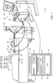
Fig. 1 is a schematic, pictorial illustration of a combined cardiac pacing and irreversible electroporation (IRE)system 20, in accordance with an exemplary embodiment of the present invention.System 20 may be configured to stimulate and analyze substantially any electrophysiological (EP) parameter or combination of such parameters. To this end, aconsole 46 ofsystem 20 comprises a combined pacing/IRE pulse generator 33 that generates and applies interweaved pacing/IRE waveforms via aprobe 24 to cardiac tissue in aheart 34 of apatient 26. - In the description herein, by way of example, the signals analyzed are assumed to be intra-cardiac and/or extra-cardiac (body surface) ECG potential-time relationships. In order to fully characterize such relationships, the signals at various locations need to be referenced in time to each other, such as is done, for example, while generating a local activation time (LAT) map. The time referencing is accomplished by measurements done relative to a reference time (e.g., instance), such as the beginning of each QRS complex of an ECG reference signal (i.e., the beginning of every heartbeat). A method for generating an LAT map is described in
U.S Patent No. 9,050,011 - In the following description,
system 20 stimulates (i.e., paces)heart 34 using a pacing andIRE probe 24.System 20 measures resulting electrical activity of aheart 34, usingprobe 24 itself and/or using anadditional probe 14. Adistal end 32 ofprobe 24 is assumed to haveelectrodes 22. The measured signals are used for, among other usages, creating an LAT map of at least a portion of the wall tissue ofheart 34. - Typically,
probe 24 comprises a mapping catheter which is inserted into the body ofpatient 26 during a mapping procedure performed by aphysician 28 usingsystem 20. As seen ininset 25, the procedure embodied inFig. 1 uses an M1-M2 bipolar electrode pair configuration ofprobe 24 for pacing (i.e., for EP stimulation) and for IRE treatment of the tissue site found as arrhythmogenic using combined pacing andIRE pulse generator 33. In an exemplary embodiment, the catheter is further configured to acquire intracardiac electrophysiological signals. - During the procedure,
patient 26 is assumed to be attached to a grounding electrode (i.e., ground patch) 23. In addition,electrodes 29 are assumed to be attached to the skin ofpatient 26, in the region ofheart 34. -
System 20 is controlled by asystem processor 40, comprising aprocessing unit 42 communicating with amemory 44. In some exemplary embodiments,memory 44, which is included insystem processor 40, stores anEP map 62 of at least a portion of wall tissue ofheart 34 ofpatient 26.Processor 40 is typically mounted inconsole 46, which comprises (a) apatient interface unit 43 to which all the catheters connect, and (b) a workstation having operating controls 38, typically including apointing device 39 such as a mouse or trackball used byphysician 28 to interact with the processor. - Processor 40 (specifically processing unit 42) runs software comprising a
probe tracker module 30, anECG module 36 comprising an arrhythmia analysis module, and a graphical user interface (GUI) 35, to operatesystem 20 and/or to graphically analyze and present results (usingEP map 62 stored in memory 44) from the disclosed heart pacing and IRE treatment workflow described inFig. 3 so as, for example, to identify sources of an arrhythmia and to treat them with IRE. - In an exemplary embodiment,
ECG module 36 is coupled to receive electrical signals fromelectrodes 22 andelectrodes 29. The module is configured to analyze the electrical signals and may present the results of the analysis in a standard ECG format, typically a graphical representation moving with time, ondisplay 48. - Probe
tracker module 30 typically tracks the location ofdistal end 32 ofprobe 24 within the heart ofpatient 26. The tracker module may use any method for probe location tracking known in the art. For example,module 30 may operate a magnetic-field based location tracking sub-system. (For simplicity, components of such sub-system are not shown inFig. 1 .) - Alternatively or additionally,
tracker module 30 may trackprobe 24 by measuring impedances betweenelectrode 23 andelectrodes 22, as well as the impedances to other electrodes which may be located on the probe. (In thiscase electrodes 22 may provide both ECG and location tracking signals.) The Carto3® system produced by Biosense-Webster (Irvine, California) uses both magnetic field location tracking and impedance measurements for location tracking. - Using
tracker module 30,processor 40 is able to measure locations ofdistal end 32. In addition, using bothtracker module 30 andECG module 36, the processor is able to measure locations of the distal end, as well as LATs of electrical signals detected at these particular locations. - Results of the operations performed by
processor 40 are presented tophysician 28 on adisplay 48, which typically presents a graphic user interface to the physician, a visual representation of the ECG signals sensed byelectrodes 22, and/or an image or map ofheart 34 while it is being investigated. In an embodiment,GUI 35 presents to the physician an EP map updated with one or more locations on the map where an identified arrhythmia originated or through which it propagated. The software may be downloaded toprocessor 40 in electronic form, over a network, for example, or it may, alternatively or additionally, be provided and/or stored on non-transitory tangible media, such as magnetic, optical, or electronic memory. -
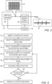
Fig. 2 is a schematic block diagram of the combined pacing andIRE pulse generator 33 of the system ofFig. 1 , in accordance with an exemplary embodiment of the present invention. In the illustrated exemplary embodiment,generator 33 comprises anIRE pulse generator 50 and a pacing/IRE waveform shaper and interleaver 55, which are both configurable and controlled byprocessor 40. - As seen,
IRE pulse generator 50 generates asequence 52 of high-voltage biphasic pulses of a predefined waveform for IRE. - A shaping circuit 55, also called hereinafter "Pacing/IRE waveform shaper and interleaver 55," converts
input sequence 52 into an interleaved pacing/IRE sequence 57 of output waveforms comprising, by way of example, M=2 IRE shape pulses interleaved with N=10 pacing pulses. - Pacing/IRE waveform shaper and pulse interleaver 55 comprises pulse shaper circuitry and waveform interleaving circuitry. The biphasic pulse shaper circuitry is configured to modify IRE pulses of
sequence 52 to a shape and repetition rate required of pacing pulses. Typically,generator 33 includes electrical elements, such as a reinforced isolated amplifier, to convert the waveform voltage from the high-voltage domain of IRE pulses into a low-voltage domain of pacing pulses. - The pulse shaper may include an array of capacitors that may produce a different rise time and fall time of the pulses. Finally, the waveform interleaver comprises a switching circuitry to switch between IRE input and pacing pulses delivered to
catheter 24. - The exemplary configurations illustrated in the
Fig. 2 is chosen purely for the sake of conceptual clarity. In alternative embodiments, the disclosed techniques may use any other suitable pulse generation and shaping scheme. -
Fig. 3 is a flow chart that schematically illustrates a method of combined cardiac pacing and irreversible electroporation (IRE) using the system ofFig. 1 . This method is not explicitly recited in the wording of the claims (but is considered as useful for understanding the invention). - The algorithm according to the presented exemplary embodiment carries out a process that begins with
physician 28 insertingcatheter 24 intoheart 34, at acatheter insertion step 70. Next,physician 28 selects, for example, a predefined protocol with a combined pacing/IRE waveform to be given to tissue, atprotocol selection step 72. As noted above,physician 28 may select to start with pacing signals only, for example, to begin a preliminary diagnosis. - Assuming a preliminary diagnosis session has ended and
physician 28 chooses to apply a mixture of pacing and IRE pulses, such as shown bywaveform 57 ofFig. 2 ,physician 28 specifies an interleaved sequence of IRE/RFA waveforms, for example, as specified by the selected protocol, at an interleavedsequence selection step 74. For example,physician 30 may select an {M=15, N=3} sequence, as defined above. - Next, at
catheter positioning step 76,physician 30 manipulatescatheter 24 to establish contact between electrodes M1-M2 ofcatheter 24 and tissue, such as of an ostium of a pulmonary vein. Next,physician 28 applies the selected interleaved sequence of pacing/IRE pulses to tissue, at a pacing/IRE application step 78. - Immediately after treatment, at a post pacing/IRE application diagnostic step 80, using electrodes M1-M2 of
catheter 24 as diagnostic electrodes,physician 28 acquires electrograms to check to whatextent treatment step 78 achieved isolation. If, at a checkingstep 82, the physician finds that sufficient isolation was achieved,physician 30 then removes the catheter from the patient body, at acatheter retraction step 84. Otherwise,physician 28 may loop back to step 76 to reposition the catheter and continue the session. - Although the exemplary embodiments described herein mainly address cardiac applications, the methods and systems described herein can also be used in various other medical applications.
- It will thus be appreciated that the embodiments described above are cited by way of example, and that the present invention is not limited to what has been particularly shown and described hereinabove. Rather, the scope of the present invention includes both combinations and sub-combinations of the various features described hereinabove, as well as variations and modifications thereof which would occur to persons skilled in the art upon reading the foregoing description and which are not disclosed in the prior art.
Claims (4)
- A cardiac pacing and irreversible electroporation (IRE) apparatus (20), comprising:a pulse generator (33), which is configured to generate IRE pulses of prespecified shape and repetition rate; anda shaping circuit (55), which is configured to receive the IRE pulses from the pulse generator and convert some of the received IRE pulses into pacing pulses of prespecified frequency and amplitude, to generate an output signal comprising ones of the IRE pulses interleaved with ones of the pacing pulses, and to output the output signal to a probe (24) in a heart of a patient for applying the output signal to cardiac tissue.
- The apparatus according to claim 1, and comprising a processor (40) configured to:specify the shape and the repetition rate of the IRE pulses;specify the frequency and the amplitude of the pacing pulses; andspecify the interleaved output signal, by specifying a number of the one or more IRE pulses and a number of the one or more pacing pulses.
- The apparatus according to claim 1, wherein the shaping circuit is further configured to modify a prespecified shape of the IRE pulses.
- The apparatus according to claim 1, wherein the shaping circuit is configured to interleave the IRE pulses with the pacing pulses in accordance with a configurable protocol.
Applications Claiming Priority (1)
| Application Number | Priority Date | Filing Date | Title |
|---|---|---|---|
| US16/726,301 US11583332B2 (en) | 2019-12-24 | 2019-12-24 | Combined cardiac pacing and irreversible electroporation (IRE) treatment |
Publications (2)
| Publication Number | Publication Date |
|---|---|
| EP3841999A1 EP3841999A1 (en) | 2021-06-30 |
| EP3841999B1 true EP3841999B1 (en) | 2023-11-29 |
Family
ID=73856971
Family Applications (1)
| Application Number | Title | Priority Date | Filing Date |
|---|---|---|---|
| EP20216796.1A Active EP3841999B1 (en) | 2019-12-24 | 2020-12-23 | Combined cardiac pacing and irreversible electroporation (ire) treatment |
Country Status (5)
| Country | Link |
|---|---|
| US (1) | US11583332B2 (en) |
| EP (1) | EP3841999B1 (en) |
| JP (1) | JP2021102051A (en) |
| CN (1) | CN113017821A (en) |
| IL (1) | IL279274B2 (en) |
Families Citing this family (2)
| Publication number | Priority date | Publication date | Assignee | Title |
|---|---|---|---|---|
| WO2022214870A1 (en) | 2021-04-07 | 2022-10-13 | Btl Medical Technologies S.R.O. | Pulsed field ablation device and method |
| IL309432A (en) | 2021-07-06 | 2024-02-01 | Btl Medical Dev A S | Pulsed field ablation device and method |
Family Cites Families (12)
| Publication number | Priority date | Publication date | Assignee | Title |
|---|---|---|---|---|
| US5634899A (en) * | 1993-08-20 | 1997-06-03 | Cortrak Medical, Inc. | Simultaneous cardiac pacing and local drug delivery method |
| PL1696812T3 (en) | 2003-12-24 | 2015-12-31 | Univ California | Tissue ablation with irreversible electroporation |
| US8357149B2 (en) | 2008-06-05 | 2013-01-22 | Biosense Webster, Inc. | Filter for simultaneous pacing and ablation |
| US8221411B2 (en) | 2008-07-28 | 2012-07-17 | Medtronic, Inc. | Systems and methods for cardiac tissue electroporation ablation |
| WO2011159641A1 (en) | 2010-06-14 | 2011-12-22 | Old Dominion University Research Foundation | Stimulation waveform and system for polarity-independent cardiac resynchronization |
| US20130030430A1 (en) | 2011-07-29 | 2013-01-31 | Stewart Mark T | Intracardiac tools and methods for delivery of electroporation therapies |
| US9277957B2 (en) | 2012-08-15 | 2016-03-08 | Ethicon Endo-Surgery, Inc. | Electrosurgical devices and methods |
| US9050011B2 (en) | 2012-12-26 | 2015-06-09 | Biosense Webster (Israel) Ltd. | Removal of artifacts from map data |
| WO2015171921A2 (en) | 2014-05-07 | 2015-11-12 | Mickelson Steven R | Methods and apparatus for selective tissue ablation |
| US10271893B2 (en) * | 2014-12-15 | 2019-04-30 | Medtronic Ablation Frontiers Llc | Timed energy delivery |
| WO2017024123A1 (en) | 2015-08-06 | 2017-02-09 | Medtronic, Inc. | Cardiac pulsed field ablation |
| US9987081B1 (en) | 2017-04-27 | 2018-06-05 | Iowa Approach, Inc. | Systems, devices, and methods for signal generation |
-
2019
- 2019-12-24 US US16/726,301 patent/US11583332B2/en active Active
-
2020
- 2020-12-07 IL IL279274A patent/IL279274B2/en unknown
- 2020-12-18 JP JP2020210001A patent/JP2021102051A/en active Pending
- 2020-12-23 EP EP20216796.1A patent/EP3841999B1/en active Active
- 2020-12-24 CN CN202011555277.2A patent/CN113017821A/en active Pending
Also Published As
| Publication number | Publication date |
|---|---|
| IL279274B1 (en) | 2023-09-01 |
| EP3841999A1 (en) | 2021-06-30 |
| US20210186593A1 (en) | 2021-06-24 |
| CN113017821A (en) | 2021-06-25 |
| JP2021102051A (en) | 2021-07-15 |
| IL279274A (en) | 2021-06-30 |
| US11583332B2 (en) | 2023-02-21 |
| IL279274B2 (en) | 2024-01-01 |
Similar Documents
| Publication | Publication Date | Title |
|---|---|---|
| US11660135B2 (en) | Generating and interleaving of irreversible-electroporation and radiofrequnecy ablation (IRE/RFA) waveforms | |
| US20200289185A1 (en) | Waveform generator and control for selective cell ablation | |
| JP7442076B2 (en) | Systems, devices, and methods for delivering pulsed electric field ablation energy to endocardial tissue | |
| US20220370125A1 (en) | Electroporation system and method of preconditioning tissue for electroporation therapy | |
| JP7402889B2 (en) | Spatial multiplexed waveforms for selective cell ablation | |
| CN107921258A (en) | Melt cardiac pulses field | |
| CN107205772A (en) | timing energy delivery | |
| JPH08505294A (en) | Device and method for monitoring signals in the heart during ablation | |
| EP3841999B1 (en) | Combined cardiac pacing and irreversible electroporation (ire) treatment | |
| US20220117655A1 (en) | Using unipolar configuration for irreversible-electroporation (ire) | |
| EP3944831A1 (en) | Automatically performing irreversible electroporation ablation during heart refractory period | |
| WO2020136168A1 (en) | Device for an electrophysiology procedure | |
| CZ33133U1 (en) | Electroporation generator for cardiac tissue ablation | |
| CN115969501A (en) | High frequency monopolar electroporation ablation | |
| JP2023543846A (en) | Pretreatment waveform for irreversible electroporation | |
| US20230346467A1 (en) | Bipolar tissue ablation in accordance with a predefined periodic set of time slots | |
| EP4201351A1 (en) | Method and system for optimizing return electrode location on the body for irreversible electroporation (ire) procedures | |
| CZ33134U1 (en) | High voltage AC power supply for electroporation purposes | |
| WO2023150215A1 (en) | Systems and methods for pulsed-field ablation with charge-balanced waveforms | |
| JP2015223421A (en) | Nerve stimulation device |
Legal Events
| Date | Code | Title | Description |
|---|---|---|---|
| PUAI | Public reference made under article 153(3) epc to a published international application that has entered the european phase |
Free format text: ORIGINAL CODE: 0009012 |
|
| STAA | Information on the status of an ep patent application or granted ep patent |
Free format text: STATUS: THE APPLICATION HAS BEEN PUBLISHED |
|
| AK | Designated contracting states |
Kind code of ref document: A1 Designated state(s): AL AT BE BG CH CY CZ DE DK EE ES FI FR GB GR HR HU IE IS IT LI LT LU LV MC MK MT NL NO PL PT RO RS SE SI SK SM TR |
|
| STAA | Information on the status of an ep patent application or granted ep patent |
Free format text: STATUS: REQUEST FOR EXAMINATION WAS MADE |
|
| 17P | Request for examination filed |
Effective date: 20211129 |
|
| RBV | Designated contracting states (corrected) |
Designated state(s): AL AT BE BG CH CY CZ DE DK EE ES FI FR GB GR HR HU IE IS IT LI LT LU LV MC MK MT NL NO PL PT RO RS SE SI SK SM TR |
|
| RAP3 | Party data changed (applicant data changed or rights of an application transferred) |
Owner name: BIOSENSE WEBSTER (ISRAEL) LTD. |
|
| RAP3 | Party data changed (applicant data changed or rights of an application transferred) |
Owner name: BIOSENSE WEBSTER (ISRAEL) LTD. |
|
| STAA | Information on the status of an ep patent application or granted ep patent |
Free format text: STATUS: EXAMINATION IS IN PROGRESS |
|
| 17Q | First examination report despatched |
Effective date: 20230131 |
|
| GRAP | Despatch of communication of intention to grant a patent |
Free format text: ORIGINAL CODE: EPIDOSNIGR1 |
|
| STAA | Information on the status of an ep patent application or granted ep patent |
Free format text: STATUS: GRANT OF PATENT IS INTENDED |
|
| RIC1 | Information provided on ipc code assigned before grant |
Ipc: A61B 18/00 20060101ALN20230530BHEP Ipc: A61N 1/32 20060101ALI20230530BHEP Ipc: A61B 18/14 20060101AFI20230530BHEP |
|
| INTG | Intention to grant announced |
Effective date: 20230628 |
|
| GRAJ | Information related to disapproval of communication of intention to grant by the applicant or resumption of examination proceedings by the epo deleted |
Free format text: ORIGINAL CODE: EPIDOSDIGR1 |
|
| STAA | Information on the status of an ep patent application or granted ep patent |
Free format text: STATUS: EXAMINATION IS IN PROGRESS |
|
| GRAP | Despatch of communication of intention to grant a patent |
Free format text: ORIGINAL CODE: EPIDOSNIGR1 |
|
| STAA | Information on the status of an ep patent application or granted ep patent |
Free format text: STATUS: GRANT OF PATENT IS INTENDED |
|
| INTC | Intention to grant announced (deleted) | ||
| RIC1 | Information provided on ipc code assigned before grant |
Ipc: A61B 18/00 20060101ALN20230904BHEP Ipc: A61N 1/32 20060101ALI20230904BHEP Ipc: A61B 18/14 20060101AFI20230904BHEP |
|
| GRAS | Grant fee paid |
Free format text: ORIGINAL CODE: EPIDOSNIGR3 |
|
| INTG | Intention to grant announced |
Effective date: 20230918 |
|
| GRAA | (expected) grant |
Free format text: ORIGINAL CODE: 0009210 |
|
| STAA | Information on the status of an ep patent application or granted ep patent |
Free format text: STATUS: THE PATENT HAS BEEN GRANTED |
|
| AK | Designated contracting states |
Kind code of ref document: B1 Designated state(s): AL AT BE BG CH CY CZ DE DK EE ES FI FR GB GR HR HU IE IS IT LI LT LU LV MC MK MT NL NO PL PT RO RS SE SI SK SM TR |
|
| REG | Reference to a national code |
Ref country code: GB Ref legal event code: FG4D |
|
| REG | Reference to a national code |
Ref country code: CH Ref legal event code: EP |
|
| REG | Reference to a national code |
Ref country code: DE Ref legal event code: R096 Ref document number: 602020021828 Country of ref document: DE |
|
| REG | Reference to a national code |
Ref country code: IE Ref legal event code: FG4D |
|
| PGFP | Annual fee paid to national office [announced via postgrant information from national office to epo] |
Ref country code: FR Payment date: 20231212 Year of fee payment: 4 Ref country code: DE Payment date: 20231128 Year of fee payment: 4 |
|
| REG | Reference to a national code |
Ref country code: LT Ref legal event code: MG9D |
|
| REG | Reference to a national code |
Ref country code: NL Ref legal event code: MP Effective date: 20231129 |
|
| PG25 | Lapsed in a contracting state [announced via postgrant information from national office to epo] |
Ref country code: GR Free format text: LAPSE BECAUSE OF FAILURE TO SUBMIT A TRANSLATION OF THE DESCRIPTION OR TO PAY THE FEE WITHIN THE PRESCRIBED TIME-LIMIT Effective date: 20240301 |
|
| PG25 | Lapsed in a contracting state [announced via postgrant information from national office to epo] |
Ref country code: IS Free format text: LAPSE BECAUSE OF FAILURE TO SUBMIT A TRANSLATION OF THE DESCRIPTION OR TO PAY THE FEE WITHIN THE PRESCRIBED TIME-LIMIT Effective date: 20240329 |
|
| PG25 | Lapsed in a contracting state [announced via postgrant information from national office to epo] |
Ref country code: LT Free format text: LAPSE BECAUSE OF FAILURE TO SUBMIT A TRANSLATION OF THE DESCRIPTION OR TO PAY THE FEE WITHIN THE PRESCRIBED TIME-LIMIT Effective date: 20231129 |