EP3841340B1 - Verstellbare zusatzbeleuchtung für ein gerät - Google Patents
Verstellbare zusatzbeleuchtung für ein gerät Download PDFInfo
- Publication number
- EP3841340B1 EP3841340B1 EP19852908.3A EP19852908A EP3841340B1 EP 3841340 B1 EP3841340 B1 EP 3841340B1 EP 19852908 A EP19852908 A EP 19852908A EP 3841340 B1 EP3841340 B1 EP 3841340B1
- Authority
- EP
- European Patent Office
- Prior art keywords
- user interface
- signal
- brightness
- refrigerator appliance
- interface device
- Prior art date
- Legal status (The legal status is an assumption and is not a legal conclusion. Google has not performed a legal analysis and makes no representation as to the accuracy of the status listed.)
- Active
Links
Images




Classifications
-
- F—MECHANICAL ENGINEERING; LIGHTING; HEATING; WEAPONS; BLASTING
- F25—REFRIGERATION OR COOLING; COMBINED HEATING AND REFRIGERATION SYSTEMS; HEAT PUMP SYSTEMS; MANUFACTURE OR STORAGE OF ICE; LIQUEFACTION SOLIDIFICATION OF GASES
- F25D—REFRIGERATORS; COLD ROOMS; ICE-BOXES; COOLING OR FREEZING APPARATUS NOT OTHERWISE PROVIDED FOR
- F25D27/00—Lighting arrangements
- F25D27/005—Lighting arrangements combined with control means
-
- H—ELECTRICITY
- H05—ELECTRIC TECHNIQUES NOT OTHERWISE PROVIDED FOR
- H05B—ELECTRIC HEATING; ELECTRIC LIGHT SOURCES NOT OTHERWISE PROVIDED FOR; CIRCUIT ARRANGEMENTS FOR ELECTRIC LIGHT SOURCES, IN GENERAL
- H05B47/00—Circuit arrangements for operating light sources in general, i.e. where the type of light source is not relevant
- H05B47/10—Controlling the light source
- H05B47/16—Controlling the light source by timing means
-
- F—MECHANICAL ENGINEERING; LIGHTING; HEATING; WEAPONS; BLASTING
- F25—REFRIGERATION OR COOLING; COMBINED HEATING AND REFRIGERATION SYSTEMS; HEAT PUMP SYSTEMS; MANUFACTURE OR STORAGE OF ICE; LIQUEFACTION SOLIDIFICATION OF GASES
- F25D—REFRIGERATORS; COLD ROOMS; ICE-BOXES; COOLING OR FREEZING APPARATUS NOT OTHERWISE PROVIDED FOR
- F25D23/00—General constructional features
- F25D23/02—Doors; Covers
- F25D23/028—Details
-
- F—MECHANICAL ENGINEERING; LIGHTING; HEATING; WEAPONS; BLASTING
- F25—REFRIGERATION OR COOLING; COMBINED HEATING AND REFRIGERATION SYSTEMS; HEAT PUMP SYSTEMS; MANUFACTURE OR STORAGE OF ICE; LIQUEFACTION SOLIDIFICATION OF GASES
- F25D—REFRIGERATORS; COLD ROOMS; ICE-BOXES; COOLING OR FREEZING APPARATUS NOT OTHERWISE PROVIDED FOR
- F25D23/00—General constructional features
- F25D23/12—Arrangements of compartments additional to cooling compartments; Combinations of refrigerators with other equipment, e.g. stove
- F25D23/126—Water cooler
-
- H—ELECTRICITY
- H05—ELECTRIC TECHNIQUES NOT OTHERWISE PROVIDED FOR
- H05B—ELECTRIC HEATING; ELECTRIC LIGHT SOURCES NOT OTHERWISE PROVIDED FOR; CIRCUIT ARRANGEMENTS FOR ELECTRIC LIGHT SOURCES, IN GENERAL
- H05B47/00—Circuit arrangements for operating light sources in general, i.e. where the type of light source is not relevant
- H05B47/10—Controlling the light source
- H05B47/105—Controlling the light source in response to determined parameters
- H05B47/11—Controlling the light source in response to determined parameters by determining the brightness or colour temperature of ambient light
-
- H—ELECTRICITY
- H05—ELECTRIC TECHNIQUES NOT OTHERWISE PROVIDED FOR
- H05B—ELECTRIC HEATING; ELECTRIC LIGHT SOURCES NOT OTHERWISE PROVIDED FOR; CIRCUIT ARRANGEMENTS FOR ELECTRIC LIGHT SOURCES, IN GENERAL
- H05B47/00—Circuit arrangements for operating light sources in general, i.e. where the type of light source is not relevant
- H05B47/10—Controlling the light source
- H05B47/175—Controlling the light source by remote control
-
- F—MECHANICAL ENGINEERING; LIGHTING; HEATING; WEAPONS; BLASTING
- F25—REFRIGERATION OR COOLING; COMBINED HEATING AND REFRIGERATION SYSTEMS; HEAT PUMP SYSTEMS; MANUFACTURE OR STORAGE OF ICE; LIQUEFACTION SOLIDIFICATION OF GASES
- F25D—REFRIGERATORS; COLD ROOMS; ICE-BOXES; COOLING OR FREEZING APPARATUS NOT OTHERWISE PROVIDED FOR
- F25D2327/00—Lighting arrangements not provided for in other groups of this subclass
- F25D2327/001—Lighting arrangements on the external side of the refrigerator, freezer or cooling box
-
- F—MECHANICAL ENGINEERING; LIGHTING; HEATING; WEAPONS; BLASTING
- F25—REFRIGERATION OR COOLING; COMBINED HEATING AND REFRIGERATION SYSTEMS; HEAT PUMP SYSTEMS; MANUFACTURE OR STORAGE OF ICE; LIQUEFACTION SOLIDIFICATION OF GASES
- F25D—REFRIGERATORS; COLD ROOMS; ICE-BOXES; COOLING OR FREEZING APPARATUS NOT OTHERWISE PROVIDED FOR
- F25D2600/00—Control issues
- F25D2600/02—Timing
-
- H—ELECTRICITY
- H05—ELECTRIC TECHNIQUES NOT OTHERWISE PROVIDED FOR
- H05B—ELECTRIC HEATING; ELECTRIC LIGHT SOURCES NOT OTHERWISE PROVIDED FOR; CIRCUIT ARRANGEMENTS FOR ELECTRIC LIGHT SOURCES, IN GENERAL
- H05B47/00—Circuit arrangements for operating light sources in general, i.e. where the type of light source is not relevant
- H05B47/10—Controlling the light source
- H05B47/175—Controlling the light source by remote control
- H05B47/19—Controlling the light source by remote control via wireless transmission
Definitions
- the present subject matter relates generally to appliances and more particularly to adjustable auxiliary lighting for appliances.
- the invention relates to a method of operating a refrigerator appliance according to claim 1.
- Certain appliances include auxiliary lighting assemblies operatively configured to emit light so as to improve the aesthetic appearance or ease of use of the appliance.
- auxiliary lighting assemblies may be provided, e.g., in a handle of the appliance and/or a dispenser recess of the appliance.
- US 2018/0010846 A1 relates handling a lighting assembly for an appliance includes features that allow a consumer to readily change the color of the light emitted from the handle lighting assembly as desired.
- the handle lighting assembly includes features that allow a consumer to readily interchange colored films to and from the handle lighting assembly based on the desired emitted light color.
- a consumer may desire to change the brightness of the light emitted from the auxiliary lighting assembly of their appliance.
- Conventional auxiliary lighting assemblies have not provided consumers with a readily available means for changing the brightness of the emitted light.
- the present subject matter is directed to a method of operating a refrigerator appliance.
- the refrigerator appliance includes a cabinet and an auxiliary light positioned on an exterior of the cabinet.
- the method includes receiving a signal from a remote user interface device, and adjusting a brightness of the auxiliary light of the refrigerator appliance based on the received signal.
- the remote user interface device is external to the refrigerator appliance.
- the steps of receiving a signal from a remote user interface device, and adjusting a brightness of the auxiliary light of the refrigerator appliance based on the received signal include: receiving a first signal sent by the remote user interface device at a first predetermined time of day, and adjusting the brightness of the auxiliary light to a first predetermined level based on the first signal; and receiving a second signal sent by the remote user interface device at a second predetermined time of day and adjusting the brightness of the auxiliary light to a second predetermined level based on the second signal, wherein the first predetermined time and the second predetermined time of day, the first predetermined level and the second predetermined level are determined by the remote user interface device based on a user input on a user interface of the remote user interface device.
- terms of approximation such as “generally,” or “about” include values within ten percent greater or less than the stated value. When used in the context of an angle or direction, such terms include within ten degrees greater or less than the stated angle or direction.
- “generally vertical” includes directions within ten degrees of vertical in any direction, e.g., clockwise or counter-clockwise.
- FIG. 1 provides a front view of a refrigerator appliance 100 according to an exemplary embodiment of the present subject matter.
- Refrigerator appliance 100 includes a housing or cabinet 102 that extends between a top 104 and a bottom 106 along a vertical direction V, between a first side 108 and a second side 110 along a lateral direction L, and between a front side and a rear side along a transverse direction T (a direction into and out of the page in FIG. 1 , see also FIG. 4 ).
- Each of the vertical direction V, lateral direction L, and transverse direction T are mutually perpendicular to one another and form an orthogonal direction system.
- Cabinet 102 defines chilled chambers for receipt of food items for storage.
- cabinet 102 defines a fresh food chamber 122 positioned at or adjacent bottom 106 of cabinet 102 and a freezer chamber 124 arranged at or adjacent top 104 of cabinet 102.
- refrigerator appliance 100 is generally referred to as a top mount or top freezer refrigerator. It is recognized, however, that the benefits of the present disclosure apply to other types and styles of refrigerator appliances as well, such as, e.g., a bottom mount refrigerator appliance or a side-by-side style refrigerator appliance. Consequently, the description set forth herein is for illustrative purposes and is not intended to be limiting in any aspect to any particular refrigerator configuration or style.
- the present subject matter is described herein as pertaining to lighting assemblies for refrigerator appliances, the teachings and scope of the present subject matter are also applicable to other types of appliances.
- the structure and configuration of the exemplary lighting assemblies described and illustrated herein may also be applicable to other appliances with doors and/or handles, including but not limited to washers, dryers, microwaves, freezers, ovens, etc.
- Refrigerator appliance 100 can include one or more doors.
- refrigerator appliance includes refrigerator doors and freezer doors configured in a quad door configuration.
- refrigerator doors 126, 128 are rotatably hinged to an edge of cabinet 102 for selectively accessing fresh food chamber 122.
- first refrigerator door 126 is rotatably hinged to cabinet 102 proximate first side 108
- second refrigerator door 128 is rotatably hinged proximate second side 110 of refrigerator appliance 100.
- freezer doors 130, 131 are rotatably hinged to an edge of cabinet 102 for selectively accessing freezer chamber 124.
- first freezer door 130 is rotatably hinged to cabinet 102 proximate first side 108 and second freezer door 131 is rotatably hinged proximate second side 110 of refrigerator appliance 100.
- refrigerator doors 126, 128, freezer doors 130, 131 and/or cabinet 102 may define one or more sealing mechanisms (e.g., rubber gaskets) at the interface where the doors 126, 128, 130, 131 meet cabinet 102.
- Refrigerator doors 126, 128 and freezer doors 130, 131 are shown in a closed configuration in FIG. 1 . It should be appreciated that doors having a different style, position, or configuration are possible and within the scope of the present subject matter.
- Refrigerator appliance 100 also includes a dispensing assembly 132 for dispensing liquid water and/or ice.
- Dispensing assembly 132 includes a dispenser 134 positioned on or mounted to an exterior portion of refrigerator appliance 100, e.g., on refrigerator door 126.
- Dispenser 134 includes a discharging outlet 136 for accessing ice and liquid water.
- An actuating mechanism 138 shown as a paddle, is mounted below discharging outlet 136 for operating dispenser 134.
- any suitable actuating mechanism may be used to operate dispenser 134.
- dispenser 134 can include a sensor (such as an ultrasonic sensor) or a button rather than the paddle.
- a control panel 140 is provided for controlling the mode of operation.
- control panel 140 includes a plurality of user inputs (not labeled), such as a water dispensing button and an ice-dispensing button, for selecting a desired mode of operation such as crushed or non-crushed ice.
- control panel 140 may be or include a touchscreen, where the user inputs, e.g., buttons, are defined areas on the touchscreen.
- the illustrated refrigerator appliance 100 further includes at least one auxiliary light positioned on an exterior of the cabinet 102, e.g., a dispenser light 146 as may be seen in FIG. 1 .
- Discharging outlet 136 and actuating mechanism 138 are an external part of dispenser 134 and are mounted in a dispenser recess 142.
- Dispenser recess 142 is positioned at a predetermined elevation convenient for a user to access ice or water and enabling the user to access ice without the need to open refrigerator doors 126, 128.
- dispenser recess 142 is positioned at a level that approximates the waist level of an adult user.
- the dispensing assembly 132 may receive ice from an icemaker disposed in a sub-compartment of the fresh food chamber 122 or disposed within the freezer chamber 124.
- the dispenser light 146 may be positioned within the dispenser recess 142 in order to illuminate the dispenser recess 142 and/or adjacent ambient environment around the exterior of the refrigerator appliance 100.
- Refrigerator appliance 100 further includes a controller 144. Operation of the refrigerator appliance 100 is controlled by controller 144.
- control panel 140 can represent a general purpose I/O ("GPIO") device or functional block.
- control panel 140 can include input components, such as one or more of a variety of electrical, mechanical or electro-mechanical input devices including rotary dials, push buttons, touch pads, and touch screens.
- Control panel 140 can be communicatively coupled with controller 144 via one or more signal lines or shared communication busses. Additionally or alternatively, control panel 140 can be communicatively coupled with controller 144 via one or more wireless connections. Control panel 140 provides selections for user manipulation of the operation of refrigerator appliance 100.
- controller 144 In response to user manipulation of control panel 140, controller 144 operates various components of refrigerator appliance 100.
- controller 144 is operatively coupled or in communication with various components such as one or more auxiliary lights, e.g., the dispenser light 146 described above or a handle lighting assembly, as discussed below.
- Controller 144 includes memory and one or more processing devices such as microprocessors, CPUs or the like, such as general or special purpose microprocessors operable to execute programming instructions or micro-control code associated with operation of refrigerator appliance 100.
- the memory can represent random access memory such as DRAM, or read only memory such as ROM or FLASH.
- the processor executes programming instructions stored in the memory.
- the memory can be a separate component from the processor or can be included onboard within the processor.
- controller 144 may be constructed without using a microprocessor, e.g., using a combination of discrete analog and/or digital logic circuitry (such as switches, amplifiers, integrators, comparators, flipflops, AND gates, and the like) to perform control functionality instead of relying upon software.
- each door 126, 128, 130, 131 of refrigerator appliance 100 includes a handle assembly 200 for accessing one of the chilled chambers 122, 124 of refrigerator appliance 100.
- handle assembly 200 of each door 126, 128, 130, 131 is configured as a pocket handle and each handle assembly 200 extends generally along the vertical direction V along the length of its respective door 126, 128, 130, 131 as shown.
- handle assemblies 200 need not extend the length of their respective doors.
- handle assemblies 200 can extend along the vertical direction V over approximately half of the length of their respective doors 126, 128, 130, 131.
- pocket handles may be used to move refrigerator doors 126, 128 or freezer doors 130, 132 between an open and closed position.
- Pocket handles are generally integral to the door and are created by forming a recess in a door body.
- a hand grip recess may be created on the side or front surface of a door, thereby allowing a user to manipulate the door.
- Pocket handles can be different sizes, depths, and locations so as to enable a user to grip the door.
- pocket handles can be used to open and close each of the pair of refrigerator doors 126, 128 or freezer doors 130, 132.
- one or more handle assemblies 200 of refrigerator appliance 100 include a handle lighting assembly operatively configured to emit light from their respective handle assemblies 200.
- a handle lighting assembly operatively configured to emit light from their respective handle assemblies 200.
- One or more aspects, e.g., brightness, of the light emitted from the handle assemblies 200 may be adjustable, e.g., by the controller 144.
- FIG. 2 provides a side elevation view of refrigerator door 126 of the exemplary refrigerator appliance 100 of FIG. 1 depicting handle assembly 200.
- FIG. 2 provides a side view of handle assembly 200 of refrigerator door 126 from View A of FIG. 1 .
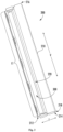
- FIG. 3 provides a perspective view of handle assembly 200 thereof removed from door 126 for illustrative purposes.
- handle assembly 200 is configured as a pocket handle, as noted above.
- handle assembly 200 includes a handle body 210.
- Handle body 210 extends between a front 212 and a rear 214 along the transverse direction T ( FIG. 3 ), and for this embodiment, handle body 210 is disposed between an inner wall 150 and an outer wall 152 of refrigerator door 126 ( FIG. 2 ).
- Handle body 210 also extends between a top 216 and a bottom 218 along the vertical direction V ( FIG. 3 ), and for this embodiment, handle body 210 is disposed between a top wall 156 and a bottom wall 158 of refrigerator door 126 ( FIG. 2 ).
- Handle body 210 can be formed integrally with refrigerator door 126 or can be a component separate from the door.
- Handle body 210 defines a recess 220.
- Recess 220 is defined along the vertical direction V substantially along a length L1 of handle body 210 ( FIG. 3 ).
- a user can reach into recess 220 and can pull refrigerator door 126 open.
- handle assembly 200 includes a handle lighting assembly 300 connected to handle body 210.
- handle lighting assembly 300 is disposed within recess 220 defined by handle body 210.
- handle lighting assembly 300 can be formed integrally with handle body 210.
- handle lighting assembly 300 extends substantially along the length L1 of handle body 210.
- handle lighting assembly 300 need not extend substantially along the length L1 of handle body 210.
- handle lighting assembly 300 can extend half the length L1 of handle body 210.
- FIG. 4 provides a cross-sectional view of refrigerator doors 126, 128 of the exemplary refrigerator appliance 100 of FIG. 1 in a closed configuration.
- refrigerator door 126 of refrigerator appliance 100 includes inner wall 150 and outer wall 152.
- Inner wall 150 generally defines a portion of the interior of fresh food chamber 122 when door 126 is in a closed position.
- Outer wall 152 is generally opposite inner wall 150 and defines a portion of the exterior of refrigerator appliance 100 when door 126 is in the closed position.
- Door 126 includes side walls 154 extending between and connecting inner wall 150 and outer wall 152.
- a foam or other insulating material is disposed between inner wall 150 and outer wall 152 along the transverse direction T, as well as between the side walls 154 along the lateral direction L.
- handle body 210 forms side wall 154 proximate a lateral centerline LC defined by refrigerator appliance 100 orthogonal to the lateral direction L at a center point of the refrigerator appliance 100 along the lateral direction L.
- refrigerator door 128 can be configured in the same or similar manner as refrigerator door 126.
- freezer doors 130, 131 can likewise include inner, outer, and side walls 150, 152, 154 as shown and described for refrigerator door 126.
- first recess 222 defined by handle body 210 of refrigerator door 126 and second recess 224 defined by handle body 210 of refrigerator door 128 define an illumination recess 226.
- a gap G is defined between refrigerator door 126 and refrigerator door 128 along the lateral direction L such that when one or more of the light sources of the respective first and second handle lighting assemblies 302, 304 emit light, the light from within the illumination recess 226 escapes through gap G and thus may be visible from an exterior of refrigerator appliance 100 (e.g., FIG. 1 ). In this manner, the aesthetic appearance and ease of use of refrigerator appliance 100 can be enhanced.
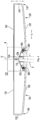
- FIG. 5 provides a close up view of Section B of FIG. 4 depicting handle assemblies of refrigerator doors 126, 128, respectively.
- the handle lighting assembly disposed within the recess of refrigerator door 126 is a first handle lighting assembly 302 and the handle lighting assembly disposed within the recess of refrigerator door 128 is a second handle lighting assembly 304.
- first handle lighting assembly 302 is disposed within first recess 222 defined by first handle assembly 202 and second handle lighting assembly 304 is disposed within second recess 224 defined by second handle assembly 204.
- Each handle lighting assembly 300 includes one or more light sources 352.
- the light sources 352 can be any suitable type of light source, such as e.g., LEDs, OLEDs, incandescent, halogen, fluorescent, high intensity discharge, a combination of the foregoing, etc.
- Each lighting assembly 300 may be communicatively coupled with controller 144.
- controller 144 is operatively configured to control the lumen intensity of the of light source(s) of each lighting assembly 300. As such, controller 144 can dim or turn off the lighting assemblies 300 in accordance with a set schedule or upon a user input, as described in more detail below.
- Each handle lighting assembly 300 includes a lens 342. Moreover, as shown in FIG. 5 , for this exemplary embodiment, lens 342 has an arcuate shape.
- a reference plane RP is disposed in a plane coplanar with a front face 360 or point of light source 352.
- a film 370 may be provided over the light sources 352 and may be curved towards reference plane RP while lens 342 curves away from reference plane RP.
- film 370 may be a diverging lens and lens 342 may be a converging lens.
- light source 352 emits light from first handle assembly 202
- the light initially passes through film 370. Due to the curvature of film 370, the light diverges as it passes therethrough. The divergence of the light allows the light to spread out over the entire surface of lens 342.
- the diverging light passes through convex lens 342.
- Lens 342 converges or focuses the light at the rear sidewall 228 of the second handle assembly 204.
- the light may then reflect off of the rear sidewall 228 of the second handle assembly 204 and a portion of the reflected light can exit through gap G.
- the light may be directed in the same manner as noted above for light emitted from first handle assembly 202.
- the light escaping through gap G provides refrigerator appliance 100 with illumination originating from the pocket handles of refrigerator appliance 100 (e.g., FIG. 1 ). In this way, the aesthetic appearance and ease of use of refrigerator appliance 100 can be enhanced.
- the refrigerator appliance 100 and in particular the controller 144 thereof, is configured to receive a signal 1100 from a remote user device 1000 external to the refrigerator appliance 100.
- the signal 1100 may, for example, be a short-range radio signal or other suitable wireless signal.
- the refrigerator appliance 100 may communicate with the remote user interface device 1000 via short-range radio such as BLUETOOTH ® or any other suitable wireless network having a layer protocol architecture.
- short-range may include ranges of about ten meters or less, up to about one hundred meters.
- the wireless network may be adapted for short-wavelength ultra-high frequency (UHF) communications in a band between 2.4 GHz and 2.485 GHz (e.g., according to the IEEE 802.15.1 standard).
- UHF ultra-high frequency
- the refrigerator 100 and the remote user interface device 1000 may communicate via WIFI ® , infrared signals, or any other suitable wireless communication protocol or method.
- the remote user interface device 1000 may also include a user interface 1002, e.g., a touchscreen, for receiving user inputs.
- the remote user interface device 1000 may be a laptop computer, smartphone, tablet, personal computer, wearable device, smart home system, and/or various other suitable devices including a user interface such as a touchscreen display 1002.
- the remote user interface device 1000 may include a memory for storing and retrieving programming instructions.
- the remote user interface device 1000 may provide a remote user interface which may be an additional user interface to the control panel 140.
- the remote user interface device 1000 may be a smartphone operable to store and run applications, also known as "apps.”
- the remote user interface device 1000 may be configured to receive a user input via the user interface 1002, and to send the signal 1100 to the refrigerator appliance 100 based on the received user input.
- the controller 144 of the refrigerator appliance 100 may be operable to receive the signal 1100 from the remote user interface device 1000 and to operate, e.g., adjust one or more operating parameters of, the auxiliary light, e.g., dispenser light 146 and/or handle light 300 as described above, based on the received signal 1100 from the remote user interface device 1000.
- FIG. 7 illustrates an exemplary configuration of the user interface 1002 of the remote user interface device.
- the user interface includes an ON input 1004 and an OFF input 1006.
- the ON input 1004 is shaded to indicate that it is active.
- a portion of the touchscreen 1002 may be illuminated to indicate the active or selected input, as shown by shading in FIGS. 7 and 8 .
- the remote user interface device 1000 may send a signal to the controller 144 of the refrigerator 100 based on a user's selection of one or more inputs on the user interface 1002 of the remote user interface device 1000, and the signal may be indicative of and/or may correspond to the selected input.
- the remote user interface device 1000 may send a signal to the controller 144, the controller 144 may receive the signal, and the controller 144 may then turn the auxiliary light, e.g., handle light 300 and/or dispenser light 146, ON based on the received signal.
- the auxiliary light e.g., handle light 300 and/or dispenser light 146
- the user interface 1002 may then provide additional inputs, such as the Day/Night input 1008 and the Brightness Level input 1010 illustrated in FIG. 7 .
- the remote user interface device 1000 may be configured to receive a user input or selection via one of the inputs 1008 and 1010 after receiving or detecting a user selection of the ON input 1004.
- the Day/Night input 1008 has been selected and/or is activated, which the user interface 1002 may confirm by illuminating or otherwise highlighting the Day/Night input 1008, e.g., as shown by shading in FIG. 7 .
- the Day/Night input 1008 may correspond to an automatic operating mode.
- the automatic operating mode may include one or more threshold times and corresponding brightness settings for the auxiliary light based on the time of day.
- the remote user interface device 1000 is configured to receive or determine a first predetermined time of day, e.g., a morning threshold, and a second predetermined time of day, e.g., an evening threshold, on the user interface 1002, and may automatically send signals to the refrigerator appliance 100 at the predetermined times of day.
- the morning threshold may be six o'clock (6:00) AM
- the remote user interface device 1000 may send a signal 1100 to the refrigerator appliance 100 automatically when the remote user interface device 1000 determines that the time of day is equal to the morning threshold, e.g., at six o'clock AM.
- the signal 1100 sent at the morning threshold may correspond to or indicate a first predetermined brightness level, e.g., a day brightness setting, and the controller 144 of the refrigerator appliance 100 may receive such signal and adjust the brightness of the auxiliary light, e.g., dispenser light 146 and/or handle light 300, based on the received signal.
- the evening threshold may be eight o'clock (8:00) PM.
- the remote user interface device 1000 may send a second signal 1100 to the controller 144 at the evening threshold, whereupon the controller 144 receives the second signal 1100 and adjusts the brightness of the auxiliary light to a second predetermined level, e.g., a night setting.
- a second predetermined level e.g., a night setting.
- FIG. 8 illustrates an exemplary configuration of the user interface 1002 when a manual operation mode is active, e.g., when the Brightness Level input 1010 has been selected.
- the remote user interface device 1000 may send the signal 1100 immediately after determining a brightness level setting via the user interface 1002, rather than sending the signal at one or more predetermined times, as described above.
- the brightness level setting may be determined by a brightness input 1012.
- the brightness input 1012 is a slider input, where the brightness level setting may be a percentage value within a range from zero percent (0%) brightness to one hundred percent (100%) brightness. In some embodiments, any value from zero percent (0%) to one hundred percent (100%) may be selectable.
- a smaller number of brightness levels may be selectable, such as a low level, a medium level, and a high level.
- the low level may be between about five percent (5%) and about thirty-five percent (35%) brightness, such as about twenty percent (20%) brightness.
- the medium level may be between about thirty percent (30%) brightness and about eighty percent (80%) brightness, such as about fifty percent (50%) brightness.
- the high level may be between about sixty-five percent (65%) brightness and about one hundred percent (100%) brightness, such as about ninety percent (90%) brightness. In embodiments where the high level is less than one hundred percent (100%) brightness, a max level corresponding to about one hundred percent (100%) brightness may also be provided.
- only two levels may be selectable, such as a low level and a high level. In further embodiments, five or more levels may be selectable.
- the brightness of the auxiliary light may thereby be independent of an ambient light level.
- the refrigerator appliance 1000 may not include an ambient light sensor. Omitting an ambient light sensor may reduce the cost of the refrigerator appliance 100 and provide a more aesthetically pleasing appearance to the refrigerator appliance 100.
- the control panel 140 need not include an aperture for the ambient light sensor, providing a smoother and more consistent look to the surface, e.g., touchscreen surface, of the control panel 140.
- control panel 140 and controller 144 may be simplified in that a clock or means of monitoring time, e.g., downloading date and time data from the internet or receiving a time input at the control panel 140, may be omitted where the remote user interface 1000 provides appropriate signals 1100 at the desired times of day.
- a clock or means of monitoring time e.g., downloading date and time data from the internet or receiving a time input at the control panel 140
Landscapes
- Engineering & Computer Science (AREA)
- Chemical & Material Sciences (AREA)
- Combustion & Propulsion (AREA)
- Physics & Mathematics (AREA)
- Mechanical Engineering (AREA)
- Thermal Sciences (AREA)
- General Engineering & Computer Science (AREA)
- Devices That Are Associated With Refrigeration Equipment (AREA)
- Circuit Arrangements For Discharge Lamps (AREA)
- Circuit Arrangement For Electric Light Sources In General (AREA)
Claims (5)
- Verfahren zum Betreiben eines Kühlschrankgeräts (100), wobei das Kühlschrankgerät (100) einen Schrank (102) und ein Hilfslicht umfasst, das auf einem Äußeren des Schranks (102) positioniert ist, wobei das Verfahren umfasst:Empfangen eines Signals (1100) von einer Fernbedienungseinrichtung (1000) und Einstellen der Helligkeit des Hilfslichts des Kühlschrankgeräts (100) basierend auf dem empfangenen Signal (1100), dadurch gekennzeichnet, dassdie Fernbedienungseinrichtung (1000) sich außerhalb des Kühlschrankgeräts (100) befindet;die Schritte des Empfangens des Signals (1100) von der Fernbedienungseinrichtung (1000) und des Einstellens der Helligkeit des Hilfslichts des Kühlschrankgeräts (100) basierend auf dem empfangenen Signal (1100) umfassen:Empfangen eines ersten Signals (1100), das zu einer ersten vorbestimmten Tageszeit von der Fernbedienungseinrichtung (1000) gesendet wird, und Einstellen der Helligkeit des Hilfslichts auf einen ersten vorbestimmten Pegel basierend auf dem ersten Signal (1100); undEmpfangen eines zweiten Signals (1100), das zu einer zweiten vorbestimmten Tageszeit von der Fernbedienungseinrichtung (1000) gesendet wird, und Einstellen der Helligkeit des Hilfslichts auf einen zweiten vorbestimmten Pegel basierend auf dem zweiten Signal (1100), wobei die erste vorbestimmte Tageszeit und die zweite vorbestimmte Tageszeit, der erste vorbestimmte Pegel und der zweite vorbestimmte Pegel durch die Fernbedienungseinrichtung (1000) basierend auf einer Benutzereingabe über eine Benutzerschnittstelle (1002) der Fernbedienungseinrichtung (1000) bestimmt werden.
- Verfahren nach Anspruch 1, wobei die Helligkeit des Hilfslichts unabhängig von einem Umgebungslichtpegel ist.
- Verfahren nach Anspruch 1, wobei der vorbestimmte Pegel ein Pegel aus einem niedrigen Pegel, einem mittleren Pegel und einem hohen Pegel ist oder der vorbestimmte Pegel ein Prozentwert innerhalb eines Bereichs von null Prozent Helligkeit bis hundert Prozent Helligkeit ist.
- Verfahren nach Anspruch 1, wobei das erste Signal (1100) und das zweite Signal (1100) von einem Steuergerät (144) des Kühlschrankgeräts (100) empfangen werden und das Steuergerät (144) in Betriebskommunikation mit dem Hilfslicht ist; und
die erste vorbestimmte Tageszeit eine Morgenschwelle ist und der erste vorbestimmte Pegel eine Tageshelligkeit-Einstellung ist. - Verfahren nach Anspruch 1, wobei das erste Signal (1100) und das zweite Signal (1100) von einem Steuergerät (144) des Kühlschrankgeräts (100) empfangen werden und das Steuergerät (144) in Betriebskommunikation mit dem Hilfslicht ist; und
die zweite vorbestimmte Tageszeit eine Abendschwelle ist und der zweite vorbestimmte Pegel eine Nachthelligkeitspegel-Einstellung ist.
Applications Claiming Priority (2)
| Application Number | Priority Date | Filing Date | Title |
|---|---|---|---|
| US16/105,012 US20200056832A1 (en) | 2018-08-20 | 2018-08-20 | Adjustable auxiliary lighting for an appliance |
| PCT/CN2019/100620 WO2020038267A1 (en) | 2018-08-20 | 2019-08-14 | Adjustable auxiliary lighting for an appliance |
Publications (3)
| Publication Number | Publication Date |
|---|---|
| EP3841340A1 EP3841340A1 (de) | 2021-06-30 |
| EP3841340A4 EP3841340A4 (de) | 2021-10-13 |
| EP3841340B1 true EP3841340B1 (de) | 2023-10-04 |
Family
ID=69523831
Family Applications (1)
| Application Number | Title | Priority Date | Filing Date |
|---|---|---|---|
| EP19852908.3A Active EP3841340B1 (de) | 2018-08-20 | 2019-08-14 | Verstellbare zusatzbeleuchtung für ein gerät |
Country Status (5)
| Country | Link |
|---|---|
| US (1) | US20200056832A1 (de) |
| EP (1) | EP3841340B1 (de) |
| CN (1) | CN112654825A (de) |
| AU (1) | AU2019323413B2 (de) |
| WO (1) | WO2020038267A1 (de) |
Families Citing this family (5)
| Publication number | Priority date | Publication date | Assignee | Title |
|---|---|---|---|---|
| DE102020208158A1 (de) * | 2020-06-30 | 2021-12-30 | BSH Hausgeräte GmbH | Haushaltsgerät mit einem Verschlusselement und einer spezifisch geformten Griffmulde an einer Schmalseite des Verschlusselements |
| CN213631151U (zh) * | 2020-07-14 | 2021-07-06 | 博西家用电器(中国)有限公司 | 用于家用电器的金属件及家用电器 |
| CN113465287B (zh) * | 2020-07-14 | 2023-02-03 | 青岛海信电子产业控股股份有限公司 | 一种智能冰箱及光照强度调整方法 |
| EP4184094A1 (de) * | 2021-11-19 | 2023-05-24 | Liebherr-Hausgeräte Marica EOOD | Kühl- und / oder gefriergerät mit einer beleuchtbaren griffmulde |
| US20250257936A1 (en) * | 2024-02-12 | 2025-08-14 | Haier Us Appliance Solutions, Inc. | Refrigerator appliance and assembly for code reading |
Citations (1)
| Publication number | Priority date | Publication date | Assignee | Title |
|---|---|---|---|---|
| US20170248925A1 (en) * | 2016-02-25 | 2017-08-31 | General Electric Company | Consumer Appliance with a Detachable Tablet |
Family Cites Families (12)
| Publication number | Priority date | Publication date | Assignee | Title |
|---|---|---|---|---|
| JPH1130468A (ja) * | 1997-07-08 | 1999-02-02 | Fujitsu General Ltd | 電気冷蔵庫の制御方法およびその装置 |
| CN103673495A (zh) * | 2012-09-25 | 2014-03-26 | 海尔集团公司 | 一种冰箱照明装置及方法 |
| JP6357397B2 (ja) * | 2014-10-09 | 2018-07-11 | 日立アプライアンス株式会社 | 冷蔵庫 |
| CN104482697B (zh) * | 2014-10-31 | 2017-07-11 | 黄巧玲 | 冰箱 |
| CN204421478U (zh) * | 2015-01-12 | 2015-06-24 | 深圳市诺科科技有限公司 | 一种基于手机wifi控制的车载冰箱 |
| CN205316805U (zh) * | 2016-01-25 | 2016-06-15 | 李军卫 | 一种带外光源的冰箱 |
| US10371438B2 (en) * | 2016-04-29 | 2019-08-06 | Whirlpool Corporation | Refrigerator having interior lighting used for synchronized user feedback of zone selection |
| CN205718156U (zh) * | 2016-05-23 | 2016-11-23 | 合肥美的电冰箱有限公司 | 一种冰箱 |
| US10415876B2 (en) * | 2016-07-11 | 2019-09-17 | Haier Us Appliance Solutions, Inc. | Handle lighting assembly for an appliance |
| US10295248B2 (en) * | 2017-01-09 | 2019-05-21 | Electrolux Home Products, Inc. | Refrigerator with glass door |
| CN207471880U (zh) * | 2017-11-09 | 2018-06-08 | 苏州雪电通讯科技股份有限公司 | 车载冷藏冷冻箱 |
| CN108397950A (zh) * | 2018-01-05 | 2018-08-14 | 青岛海尔股份有限公司 | 制冷设备及其控制方法 |
-
2018
- 2018-08-20 US US16/105,012 patent/US20200056832A1/en not_active Abandoned
-
2019
- 2019-08-14 EP EP19852908.3A patent/EP3841340B1/de active Active
- 2019-08-14 WO PCT/CN2019/100620 patent/WO2020038267A1/en not_active Ceased
- 2019-08-14 CN CN201980054750.8A patent/CN112654825A/zh active Pending
- 2019-08-14 AU AU2019323413A patent/AU2019323413B2/en active Active
Patent Citations (1)
| Publication number | Priority date | Publication date | Assignee | Title |
|---|---|---|---|---|
| US20170248925A1 (en) * | 2016-02-25 | 2017-08-31 | General Electric Company | Consumer Appliance with a Detachable Tablet |
Also Published As
| Publication number | Publication date |
|---|---|
| US20200056832A1 (en) | 2020-02-20 |
| EP3841340A4 (de) | 2021-10-13 |
| WO2020038267A1 (en) | 2020-02-27 |
| AU2019323413A1 (en) | 2021-03-18 |
| EP3841340A1 (de) | 2021-06-30 |
| CN112654825A (zh) | 2021-04-13 |
| AU2019323413B2 (en) | 2022-07-21 |
Similar Documents
| Publication | Publication Date | Title |
|---|---|---|
| AU2019323413B2 (en) | Adjustable auxiliary lighting for an appliance | |
| US10415876B2 (en) | Handle lighting assembly for an appliance | |
| US10260790B2 (en) | Refrigerator appliance having an ice storage bin | |
| US10398260B2 (en) | Oven and control method thereof | |
| KR102619657B1 (ko) | 냉장고와 서버 및 서버의 제어 방법 | |
| EP2299220B1 (de) | Kühlschrank | |
| US20100058792A1 (en) | Refrigerator | |
| CN106871532B (zh) | 冰箱 | |
| CN101373116A (zh) | 冰箱 | |
| CN110332759A (zh) | 一种化妆品冰箱的智能系统及其智能控制方法 | |
| US9897372B2 (en) | Integrated lighting system for the interior liner of an appliance | |
| US11852402B2 (en) | Home appliance and refrigerator | |
| KR20140127589A (ko) | 냉장고 | |
| CN217844424U (zh) | 冰箱 | |
| CN106288615B (zh) | 具有包括把手槽的门页的家用器具 | |
| CN102384625A (zh) | 用于冰箱的门体及具有其的冰箱 | |
| CN117366972A (zh) | 冰箱 | |
| US9546809B2 (en) | Refrigerator appliance | |
| CN108120205A (zh) | 冰箱 | |
| WO2023160682A1 (zh) | 用于制冷电器的齐平安装灯组件 | |
| US20250290687A1 (en) | Refrigerator | |
| US20230121318A1 (en) | Refrigerator appliance with a meat aging compartment | |
| CN117387276A (zh) | 冰箱 | |
| US11796249B2 (en) | Single button capacitive user interface | |
| JP7550029B2 (ja) | 冷蔵庫 |
Legal Events
| Date | Code | Title | Description |
|---|---|---|---|
| STAA | Information on the status of an ep patent application or granted ep patent |
Free format text: STATUS: THE INTERNATIONAL PUBLICATION HAS BEEN MADE |
|
| PUAI | Public reference made under article 153(3) epc to a published international application that has entered the european phase |
Free format text: ORIGINAL CODE: 0009012 |
|
| STAA | Information on the status of an ep patent application or granted ep patent |
Free format text: STATUS: REQUEST FOR EXAMINATION WAS MADE |
|
| 17P | Request for examination filed |
Effective date: 20210322 |
|
| AK | Designated contracting states |
Kind code of ref document: A1 Designated state(s): AL AT BE BG CH CY CZ DE DK EE ES FI FR GB GR HR HU IE IS IT LI LT LU LV MC MK MT NL NO PL PT RO RS SE SI SK SM TR |
|
| STAA | Information on the status of an ep patent application or granted ep patent |
Free format text: STATUS: EXAMINATION IS IN PROGRESS |
|
| A4 | Supplementary search report drawn up and despatched |
Effective date: 20210915 |
|
| RIC1 | Information provided on ipc code assigned before grant |
Ipc: H05B 47/16 20200101ALI20210909BHEP Ipc: H05B 47/11 20200101ALI20210909BHEP Ipc: F25D 27/00 20060101ALI20210909BHEP Ipc: F25D 23/02 20060101ALI20210909BHEP Ipc: H05B 47/19 20200101ALI20210909BHEP Ipc: F25D 11/02 20060101AFI20210909BHEP |
|
| 17Q | First examination report despatched |
Effective date: 20210927 |
|
| DAV | Request for validation of the european patent (deleted) | ||
| DAX | Request for extension of the european patent (deleted) | ||
| GRAP | Despatch of communication of intention to grant a patent |
Free format text: ORIGINAL CODE: EPIDOSNIGR1 |
|
| STAA | Information on the status of an ep patent application or granted ep patent |
Free format text: STATUS: GRANT OF PATENT IS INTENDED |
|
| INTG | Intention to grant announced |
Effective date: 20230426 |
|
| GRAS | Grant fee paid |
Free format text: ORIGINAL CODE: EPIDOSNIGR3 |
|
| GRAA | (expected) grant |
Free format text: ORIGINAL CODE: 0009210 |
|
| STAA | Information on the status of an ep patent application or granted ep patent |
Free format text: STATUS: THE PATENT HAS BEEN GRANTED |
|
| AK | Designated contracting states |
Kind code of ref document: B1 Designated state(s): AL AT BE BG CH CY CZ DE DK EE ES FI FR GB GR HR HU IE IS IT LI LT LU LV MC MK MT NL NO PL PT RO RS SE SI SK SM TR |
|
| REG | Reference to a national code |
Ref country code: GB Ref legal event code: FG4D |
|
| REG | Reference to a national code |
Ref country code: CH Ref legal event code: EP |
|
| REG | Reference to a national code |
Ref country code: DE Ref legal event code: R096 Ref document number: 602019038850 Country of ref document: DE |
|
| REG | Reference to a national code |
Ref country code: IE Ref legal event code: FG4D |
|
| REG | Reference to a national code |
Ref country code: LT Ref legal event code: MG9D |
|
| REG | Reference to a national code |
Ref country code: NL Ref legal event code: MP Effective date: 20231004 |
|
| REG | Reference to a national code |
Ref country code: AT Ref legal event code: MK05 Ref document number: 1618113 Country of ref document: AT Kind code of ref document: T Effective date: 20231004 |
|
| PG25 | Lapsed in a contracting state [announced via postgrant information from national office to epo] |
Ref country code: NL Free format text: LAPSE BECAUSE OF FAILURE TO SUBMIT A TRANSLATION OF THE DESCRIPTION OR TO PAY THE FEE WITHIN THE PRESCRIBED TIME-LIMIT Effective date: 20231004 |
|
| PG25 | Lapsed in a contracting state [announced via postgrant information from national office to epo] |
Ref country code: GR Free format text: LAPSE BECAUSE OF FAILURE TO SUBMIT A TRANSLATION OF THE DESCRIPTION OR TO PAY THE FEE WITHIN THE PRESCRIBED TIME-LIMIT Effective date: 20240105 |
|
| PG25 | Lapsed in a contracting state [announced via postgrant information from national office to epo] |
Ref country code: IS Free format text: LAPSE BECAUSE OF FAILURE TO SUBMIT A TRANSLATION OF THE DESCRIPTION OR TO PAY THE FEE WITHIN THE PRESCRIBED TIME-LIMIT Effective date: 20240204 |
|
| PG25 | Lapsed in a contracting state [announced via postgrant information from national office to epo] |
Ref country code: LT Free format text: LAPSE BECAUSE OF FAILURE TO SUBMIT A TRANSLATION OF THE DESCRIPTION OR TO PAY THE FEE WITHIN THE PRESCRIBED TIME-LIMIT Effective date: 20231004 |
|
| PG25 | Lapsed in a contracting state [announced via postgrant information from national office to epo] |
Ref country code: AT Free format text: LAPSE BECAUSE OF FAILURE TO SUBMIT A TRANSLATION OF THE DESCRIPTION OR TO PAY THE FEE WITHIN THE PRESCRIBED TIME-LIMIT Effective date: 20231004 |
|
| PG25 | Lapsed in a contracting state [announced via postgrant information from national office to epo] |
Ref country code: ES Free format text: LAPSE BECAUSE OF FAILURE TO SUBMIT A TRANSLATION OF THE DESCRIPTION OR TO PAY THE FEE WITHIN THE PRESCRIBED TIME-LIMIT Effective date: 20231004 |
|
| PG25 | Lapsed in a contracting state [announced via postgrant information from national office to epo] |
Ref country code: LT Free format text: LAPSE BECAUSE OF FAILURE TO SUBMIT A TRANSLATION OF THE DESCRIPTION OR TO PAY THE FEE WITHIN THE PRESCRIBED TIME-LIMIT Effective date: 20231004 Ref country code: IS Free format text: LAPSE BECAUSE OF FAILURE TO SUBMIT A TRANSLATION OF THE DESCRIPTION OR TO PAY THE FEE WITHIN THE PRESCRIBED TIME-LIMIT Effective date: 20240204 Ref country code: GR Free format text: LAPSE BECAUSE OF FAILURE TO SUBMIT A TRANSLATION OF THE DESCRIPTION OR TO PAY THE FEE WITHIN THE PRESCRIBED TIME-LIMIT Effective date: 20240105 Ref country code: ES Free format text: LAPSE BECAUSE OF FAILURE TO SUBMIT A TRANSLATION OF THE DESCRIPTION OR TO PAY THE FEE WITHIN THE PRESCRIBED TIME-LIMIT Effective date: 20231004 Ref country code: BG Free format text: LAPSE BECAUSE OF FAILURE TO SUBMIT A TRANSLATION OF THE DESCRIPTION OR TO PAY THE FEE WITHIN THE PRESCRIBED TIME-LIMIT Effective date: 20240104 Ref country code: AT Free format text: LAPSE BECAUSE OF FAILURE TO SUBMIT A TRANSLATION OF THE DESCRIPTION OR TO PAY THE FEE WITHIN THE PRESCRIBED TIME-LIMIT Effective date: 20231004 Ref country code: PT Free format text: LAPSE BECAUSE OF FAILURE TO SUBMIT A TRANSLATION OF THE DESCRIPTION OR TO PAY THE FEE WITHIN THE PRESCRIBED TIME-LIMIT Effective date: 20240205 |
|
| PG25 | Lapsed in a contracting state [announced via postgrant information from national office to epo] |
Ref country code: SE Free format text: LAPSE BECAUSE OF FAILURE TO SUBMIT A TRANSLATION OF THE DESCRIPTION OR TO PAY THE FEE WITHIN THE PRESCRIBED TIME-LIMIT Effective date: 20231004 Ref country code: RS Free format text: LAPSE BECAUSE OF FAILURE TO SUBMIT A TRANSLATION OF THE DESCRIPTION OR TO PAY THE FEE WITHIN THE PRESCRIBED TIME-LIMIT Effective date: 20231004 Ref country code: PL Free format text: LAPSE BECAUSE OF FAILURE TO SUBMIT A TRANSLATION OF THE DESCRIPTION OR TO PAY THE FEE WITHIN THE PRESCRIBED TIME-LIMIT Effective date: 20231004 Ref country code: NO Free format text: LAPSE BECAUSE OF FAILURE TO SUBMIT A TRANSLATION OF THE DESCRIPTION OR TO PAY THE FEE WITHIN THE PRESCRIBED TIME-LIMIT Effective date: 20240104 Ref country code: LV Free format text: LAPSE BECAUSE OF FAILURE TO SUBMIT A TRANSLATION OF THE DESCRIPTION OR TO PAY THE FEE WITHIN THE PRESCRIBED TIME-LIMIT Effective date: 20231004 Ref country code: HR Free format text: LAPSE BECAUSE OF FAILURE TO SUBMIT A TRANSLATION OF THE DESCRIPTION OR TO PAY THE FEE WITHIN THE PRESCRIBED TIME-LIMIT Effective date: 20231004 |
|
| REG | Reference to a national code |
Ref country code: DE Ref legal event code: R097 Ref document number: 602019038850 Country of ref document: DE |
|
| PG25 | Lapsed in a contracting state [announced via postgrant information from national office to epo] |
Ref country code: DK Free format text: LAPSE BECAUSE OF FAILURE TO SUBMIT A TRANSLATION OF THE DESCRIPTION OR TO PAY THE FEE WITHIN THE PRESCRIBED TIME-LIMIT Effective date: 20231004 |
|
| PG25 | Lapsed in a contracting state [announced via postgrant information from national office to epo] |
Ref country code: CZ Free format text: LAPSE BECAUSE OF FAILURE TO SUBMIT A TRANSLATION OF THE DESCRIPTION OR TO PAY THE FEE WITHIN THE PRESCRIBED TIME-LIMIT Effective date: 20231004 |
|
| PG25 | Lapsed in a contracting state [announced via postgrant information from national office to epo] |
Ref country code: SK Free format text: LAPSE BECAUSE OF FAILURE TO SUBMIT A TRANSLATION OF THE DESCRIPTION OR TO PAY THE FEE WITHIN THE PRESCRIBED TIME-LIMIT Effective date: 20231004 |
|
| PG25 | Lapsed in a contracting state [announced via postgrant information from national office to epo] |
Ref country code: SM Free format text: LAPSE BECAUSE OF FAILURE TO SUBMIT A TRANSLATION OF THE DESCRIPTION OR TO PAY THE FEE WITHIN THE PRESCRIBED TIME-LIMIT Effective date: 20231004 Ref country code: SK Free format text: LAPSE BECAUSE OF FAILURE TO SUBMIT A TRANSLATION OF THE DESCRIPTION OR TO PAY THE FEE WITHIN THE PRESCRIBED TIME-LIMIT Effective date: 20231004 Ref country code: RO Free format text: LAPSE BECAUSE OF FAILURE TO SUBMIT A TRANSLATION OF THE DESCRIPTION OR TO PAY THE FEE WITHIN THE PRESCRIBED TIME-LIMIT Effective date: 20231004 Ref country code: IT Free format text: LAPSE BECAUSE OF FAILURE TO SUBMIT A TRANSLATION OF THE DESCRIPTION OR TO PAY THE FEE WITHIN THE PRESCRIBED TIME-LIMIT Effective date: 20231004 Ref country code: EE Free format text: LAPSE BECAUSE OF FAILURE TO SUBMIT A TRANSLATION OF THE DESCRIPTION OR TO PAY THE FEE WITHIN THE PRESCRIBED TIME-LIMIT Effective date: 20231004 Ref country code: DK Free format text: LAPSE BECAUSE OF FAILURE TO SUBMIT A TRANSLATION OF THE DESCRIPTION OR TO PAY THE FEE WITHIN THE PRESCRIBED TIME-LIMIT Effective date: 20231004 Ref country code: CZ Free format text: LAPSE BECAUSE OF FAILURE TO SUBMIT A TRANSLATION OF THE DESCRIPTION OR TO PAY THE FEE WITHIN THE PRESCRIBED TIME-LIMIT Effective date: 20231004 |
|
| PLBE | No opposition filed within time limit |
Free format text: ORIGINAL CODE: 0009261 |
|
| STAA | Information on the status of an ep patent application or granted ep patent |
Free format text: STATUS: NO OPPOSITION FILED WITHIN TIME LIMIT |
|
| 26N | No opposition filed |
Effective date: 20240705 |
|
| PG25 | Lapsed in a contracting state [announced via postgrant information from national office to epo] |
Ref country code: SI Free format text: LAPSE BECAUSE OF FAILURE TO SUBMIT A TRANSLATION OF THE DESCRIPTION OR TO PAY THE FEE WITHIN THE PRESCRIBED TIME-LIMIT Effective date: 20231004 |
|
| PG25 | Lapsed in a contracting state [announced via postgrant information from national office to epo] |
Ref country code: SI Free format text: LAPSE BECAUSE OF FAILURE TO SUBMIT A TRANSLATION OF THE DESCRIPTION OR TO PAY THE FEE WITHIN THE PRESCRIBED TIME-LIMIT Effective date: 20231004 |
|
| REG | Reference to a national code |
Ref country code: CH Ref legal event code: PL |
|
| PG25 | Lapsed in a contracting state [announced via postgrant information from national office to epo] |
Ref country code: LU Free format text: LAPSE BECAUSE OF NON-PAYMENT OF DUE FEES Effective date: 20240814 |
|
| PG25 | Lapsed in a contracting state [announced via postgrant information from national office to epo] |
Ref country code: MC Free format text: LAPSE BECAUSE OF FAILURE TO SUBMIT A TRANSLATION OF THE DESCRIPTION OR TO PAY THE FEE WITHIN THE PRESCRIBED TIME-LIMIT Effective date: 20231004 Ref country code: CH Free format text: LAPSE BECAUSE OF NON-PAYMENT OF DUE FEES Effective date: 20240831 |
|
| REG | Reference to a national code |
Ref country code: BE Ref legal event code: MM Effective date: 20240831 |
|
| PG25 | Lapsed in a contracting state [announced via postgrant information from national office to epo] |
Ref country code: BE Free format text: LAPSE BECAUSE OF NON-PAYMENT OF DUE FEES Effective date: 20240831 |
|
| PG25 | Lapsed in a contracting state [announced via postgrant information from national office to epo] |
Ref country code: IE Free format text: LAPSE BECAUSE OF NON-PAYMENT OF DUE FEES Effective date: 20240814 |
|
| PG25 | Lapsed in a contracting state [announced via postgrant information from national office to epo] |
Ref country code: FI Free format text: LAPSE BECAUSE OF FAILURE TO SUBMIT A TRANSLATION OF THE DESCRIPTION OR TO PAY THE FEE WITHIN THE PRESCRIBED TIME-LIMIT Effective date: 20231004 |
|
| PGFP | Annual fee paid to national office [announced via postgrant information from national office to epo] |
Ref country code: DE Payment date: 20250812 Year of fee payment: 7 |
|
| PGFP | Annual fee paid to national office [announced via postgrant information from national office to epo] |
Ref country code: GB Payment date: 20250826 Year of fee payment: 7 |
|
| PGFP | Annual fee paid to national office [announced via postgrant information from national office to epo] |
Ref country code: FR Payment date: 20250828 Year of fee payment: 7 |
|
| PG25 | Lapsed in a contracting state [announced via postgrant information from national office to epo] |
Ref country code: CY Free format text: LAPSE BECAUSE OF FAILURE TO SUBMIT A TRANSLATION OF THE DESCRIPTION OR TO PAY THE FEE WITHIN THE PRESCRIBED TIME-LIMIT; INVALID AB INITIO Effective date: 20190814 |
|
| PG25 | Lapsed in a contracting state [announced via postgrant information from national office to epo] |
Ref country code: HU Free format text: LAPSE BECAUSE OF FAILURE TO SUBMIT A TRANSLATION OF THE DESCRIPTION OR TO PAY THE FEE WITHIN THE PRESCRIBED TIME-LIMIT; INVALID AB INITIO Effective date: 20190814 |