EP3841314B1 - Anschlussvorrichtung - Google Patents
Anschlussvorrichtung Download PDFInfo
- Publication number
- EP3841314B1 EP3841314B1 EP19758436.0A EP19758436A EP3841314B1 EP 3841314 B1 EP3841314 B1 EP 3841314B1 EP 19758436 A EP19758436 A EP 19758436A EP 3841314 B1 EP3841314 B1 EP 3841314B1
- Authority
- EP
- European Patent Office
- Prior art keywords
- elongate article
- clamping
- securing
- arrangement
- connecting device
- Prior art date
- Legal status (The legal status is an assumption and is not a legal conclusion. Google has not performed a legal analysis and makes no representation as to the accuracy of the status listed.)
- Active
Links
- 230000015572 biosynthetic process Effects 0.000 claims description 44
- 238000005755 formation reaction Methods 0.000 claims description 44
- 238000006243 chemical reaction Methods 0.000 claims description 22
- 238000000034 method Methods 0.000 claims description 11
- 230000000694 effects Effects 0.000 claims description 2
- 230000006835 compression Effects 0.000 description 6
- 238000007906 compression Methods 0.000 description 6
- 230000008901 benefit Effects 0.000 description 2
- 235000013399 edible fruits Nutrition 0.000 description 2
- 208000011092 Hand injury Diseases 0.000 description 1
- 229910000831 Steel Inorganic materials 0.000 description 1
- 238000005452 bending Methods 0.000 description 1
- 230000003993 interaction Effects 0.000 description 1
- 239000000463 material Substances 0.000 description 1
- 230000007246 mechanism Effects 0.000 description 1
- 230000004048 modification Effects 0.000 description 1
- 238000012986 modification Methods 0.000 description 1
- 230000009467 reduction Effects 0.000 description 1
- 239000010959 steel Substances 0.000 description 1
Images


Classifications
-
- F—MECHANICAL ENGINEERING; LIGHTING; HEATING; WEAPONS; BLASTING
- F16—ENGINEERING ELEMENTS AND UNITS; GENERAL MEASURES FOR PRODUCING AND MAINTAINING EFFECTIVE FUNCTIONING OF MACHINES OR INSTALLATIONS; THERMAL INSULATION IN GENERAL
- F16G—BELTS, CABLES, OR ROPES, PREDOMINANTLY USED FOR DRIVING PURPOSES; CHAINS; FITTINGS PREDOMINANTLY USED THEREFOR
- F16G11/00—Means for fastening cables or ropes to one another or to other objects; Caps or sleeves for fixing on cables or ropes
- F16G11/06—Means for fastening cables or ropes to one another or to other objects; Caps or sleeves for fixing on cables or ropes with laterally-arranged screws
-
- A—HUMAN NECESSITIES
- A01—AGRICULTURE; FORESTRY; ANIMAL HUSBANDRY; HUNTING; TRAPPING; FISHING
- A01G—HORTICULTURE; CULTIVATION OF VEGETABLES, FLOWERS, RICE, FRUIT, VINES, HOPS OR SEAWEED; FORESTRY; WATERING
- A01G17/00—Cultivation of hops, vines, fruit trees, or like trees
- A01G17/04—Supports for hops, vines, or trees
- A01G17/06—Trellis-work
-
- F—MECHANICAL ENGINEERING; LIGHTING; HEATING; WEAPONS; BLASTING
- F16—ENGINEERING ELEMENTS AND UNITS; GENERAL MEASURES FOR PRODUCING AND MAINTAINING EFFECTIVE FUNCTIONING OF MACHINES OR INSTALLATIONS; THERMAL INSULATION IN GENERAL
- F16G—BELTS, CABLES, OR ROPES, PREDOMINANTLY USED FOR DRIVING PURPOSES; CHAINS; FITTINGS PREDOMINANTLY USED THEREFOR
- F16G11/00—Means for fastening cables or ropes to one another or to other objects; Caps or sleeves for fixing on cables or ropes
- F16G11/10—Quick-acting fastenings; Clamps holding in one direction only
- F16G11/105—Clamps holding in one direction only
- F16G11/108—Clamps holding in one direction only using a ball or a cylinder
-
- A—HUMAN NECESSITIES
- A01—AGRICULTURE; FORESTRY; ANIMAL HUSBANDRY; HUNTING; TRAPPING; FISHING
- A01G—HORTICULTURE; CULTIVATION OF VEGETABLES, FLOWERS, RICE, FRUIT, VINES, HOPS OR SEAWEED; FORESTRY; WATERING
- A01G9/00—Cultivation in receptacles, forcing-frames or greenhouses; Edging for beds, lawn or the like
- A01G9/12—Supports for plants; Trellis for strawberries or the like
- A01G9/128—Fixing of plants to supports, e.g. by means of clips
-
- A—HUMAN NECESSITIES
- A01—AGRICULTURE; FORESTRY; ANIMAL HUSBANDRY; HUNTING; TRAPPING; FISHING
- A01G—HORTICULTURE; CULTIVATION OF VEGETABLES, FLOWERS, RICE, FRUIT, VINES, HOPS OR SEAWEED; FORESTRY; WATERING
- A01G17/00—Cultivation of hops, vines, fruit trees, or like trees
- A01G17/04—Supports for hops, vines, or trees
- A01G17/06—Trellis-work
- A01G2017/065—Trellis-work for supporting vines having wire-tensioning devices
Definitions
- This invention relates to connecting devices. More particularly, but not exclusively, this invention relates to connecting devices for connecting flexible elongate articles in a transverse or cross relationship to one another. This invention also relates to methods of using connecting devices.
- the growing of various agricultural produce for example fruit trees, such as vine, involve arranging the trees in rows, around which wires are arranged. Some of the wires are disposed around or between the rows to support the trees, whereas others are arranged over the rows to support netting covers. Some of the wires or cables extend cross wise, or transverse, to one another. It is often necessary to join these wires or cables. Such joining can be carried out by twisting short lengths of wire around the two cross wires.
- US2007/011851 A1 discloses a connecting device according to the preamble of claim 1 that includes a clamp, a rope and a cam.
- the clamp defines a channel and a recess communicating with the channel.
- the rope includes a first end connected to the clamp and a second end inserted through the channel.
- the cam includes a pivotal point, a furthest point from the pivotal point, and a nearest point from the pivotal point. As the rope is pulled in one direction, the cam is rotated to allow the rope to move between the wall of the channel and the cam. As the rope is pulled in the opposite direction, the cam is rotated in order to pinch the rope between the wall of the channel and the cam.
- US2003/160137 A1 discloses a cable support system for supporting an object at a desired distance below an overhead beam or other overhead structure.
- a clamp for clamping to the overhead structure are fitted to support cables that encircle objects to be supported by the cable support systems.
- the clamps have internal mechanisms to support the cables.
- the cables are then encircled around the objects and fixed relative to the clamp.
- a connecting device comprising: a first securing arrangement for securing a first elongate article to the connecting device in a first orientation of the first elongate article; a second securing arrangement for securing a second elongate article to the connecting device in a second orientation of the second elongate article; wherein the second orientation is transverse to the first orientation; a body to carry the first and second securing arrangements, the body having a forward region and a rearward region; wherein the first securing arrangement comprises a first clamping arrangement, and the second securing arrangement comprises a second clamping arrangement; the first clamping arrangement comprising a passage for the first elongate article, the passage being defined by the body, and the first clamping arrangement including a clamping member and an urging member, the clamping member being arranged for clamping the first elongate article in the passage; wherein the second clamping arrangement comprises a receiving arrangement for receiving the second elongate article, and the second
- a method of using a connecting device as described in the immediately preceding paragraph comprising securing the first elongate article to the connecting device by means of the first securing arrangement, securing the second elongate article to the connecting device by means of the second securing arrangement; wherein the step of securing the first elongate article to the first securing arrangement comprises clamping the first elongate article by means of the first clamping arrangement, and the step of securing the second elongate article to the second securing arrangement comprises clamping the second elongate article by means of the second clamping arrangement; wherein the step of securing the first elongate article comprises arranging the first elongate article within the passage; and wherein the step of securing the second elongate article to the second securing arrangement comprises arranging the second elongate article in the receiving arrangement.
- the second securing arrangement may comprise a hook formation, which may be configured to extend around the second elongate article.
- first elongate article extends crosswise to the second elongate article.
- first elongate article extends at 90° to the second elongate article.
- the first and second elongate articles may be first and second flexible elongate articles, such as wires, cables, wire ropes, tapes or the like.
- At least one of the first and second elongate articles may be a rigid elongate article, such as rebar.
- the second elongate article is the rigid elongate article.
- the first securing arrangement may comprise a first clamping arrangement.
- the second securing arrangement may comprise a second clamping arrangement.
- the body may include a housing to house the first securing arrangement.
- a nose formation may extend from the body.
- the nose formation may extend from the forward region of the body.
- the nose formation may comprise a pair of projections.
- the projections may be parallel to each other.
- a gap may be defined by the nose formation. The gap may be defined between the projections.
- the gap may receive an end region of the first elongate article.
- the first elongate article may be bent into the gap.
- the bending of the end region of the elongate article into the gap provides the advantage that it helps prevent the first elongate article catching on netting as it is installed or during use.
- the nose formation may be configured to interact with a tensioning tool to allow the tensioning tool to tension the first elongate article within the first clamping arrangement.
- the nose formation may include narrowed forward end portions to interact with the tensioning tool.
- the passage may be within the housing.
- the first elongate article may extend through the passage.
- the body may define an internal space in which the urging member is disposed.
- the internal space may communicate with the passage to allow the urging member to urge the clamping member towards the passage.
- the urging member may be arranged between the passage and the second securing arrangement.
- the passage may be arranged between the urging member and the second securing arrangement.
- the urging member may urge the clamping member away from the nose formation.
- the urging member may comprise a spring, such as a coil spring.
- the urging member may comprise a compression spring.
- the compression spring may have an inwardly tapering end.
- the compression spring may have inwardly tapering opposite ends.
- The, or each, end of the compression spring may have a frustoconical configuration.
- the step of securing the first elongate article to the first securing arrangement may comprise moving the first elongate article through the passage to move the clamping member away from the passage.
- the step of securing the first elongate article to the first securing arrangement method may thereafter comprise moving the first elongate article in the opposite direction to cause the clamping member to clamp the first elongate article.
- the first clamping arrangement may include a clamping surface for engaging the first elongate article.
- the clamping surface may be an internal surface of the body.
- the clamping member may clamp the first elongate article against the clamping surface.
- the first clamping arrangement may further include a reaction surface to provide a reaction force on the clamping member when the clamping member clamps the first elongate article against the clamping surface.
- the reaction surface may be an internal surface of the body.
- the reaction surface may be opposite the clamping surface.
- the reaction surface may be a surface defining the internal space.
- the step of clamping the first elongate article may comprise arranging the first elongate article and the clamping member between the clamping surface and the reaction surface.
- the clamping force is applied to the first elongate article from the clamping surface and the clamping member and from the reaction surface.
- the clamping surface and the reaction surface may taper towards each other.
- the clamping surface and the reaction surface may taper towards each other in a direction away from the receiving arrangement.
- the urging member may urge the clamping member in a direction away from the receiving arrangement.
- the features of the first securing arrangement of the embodiment described herein provide the advantage that when the connecting device is in use, tension on the first elongate article has a tendency to pull the clamping member into greater clamping engagement with the first elongate article, thereby preventing the first elongate article from being inadvertently released from the first securing arrangement.
- the clamping member may be a wedge, a roller or a ball.
- the roller may be a substantially cylindrical roller.
- the receiving arrangement may be provided on the body.
- the receiving arrangement may be integrally attached to the body.
- the receiving arrangement may comprise the hook formation, which may be configured to extend around the second elongate article.
- the step of securing the second elongate article to the second securing arrangement may comprise arranging the second elongate article in the hook formation.
- the receiving arrangement may be provided at the forward region of the body.
- the receiving arrangement may extend from the nose formation.
- the hook formation may extend across the body.
- the hook formation may comprise a pair of hook members arranged side by side. Each hook member may extend from a respective one of the projections. Each of the hook members may have an opening facing in the same direction relative to the body. The opening of each hook member may face the rearward region of the body.
- a web portion may extend between the hook members.
- the hook members are joined to each other by the web portion.
- the hook members may be arranged alongside each other, and may extend contiguously adjacent each other.
- the hook formation may comprise a single hook member extending across both projections. The opening of the single hook member may face the rearward region of the body.
- the step of securing the second elongate article to the second securing arrangement may comprise arranging the second elongate article to extend across the hook members.
- the hook formation may comprise a single hook member, which may extend across the body.
- the step of securing the first elongate article to the first securing arrangement may comprise holding the first elongate article under tension when the second elongate article is secured to the second securing arrangement.
- the step of securing the first elongate article to the first securing arrangement may comprise holding the first elongate article under tension when the second elongate article is clamped by the movable member to the hook formation.
- the second elongate article may be selected from a plurality of second elongate articles having different widths or diameters.
- the body may include cooperating formations to cooperate with the cooperating portion of the movable member, thereby effecting the aforesaid movement of the movable member.
- the second clamping arrangement may include a holder on the body to hold the movable member.
- the holder may include the cooperating formations.
- the movable member may include the clamping portion.
- the cooperating portion may be a threaded portion.
- the formations on the body may be corresponding threads.
- the threaded portion may cooperate with the corresponding threads on the body.
- the movable member may comprise a bolt.
- the second securing arrangement may include a discrete fastening member held by the body.
- the fastening member may comprise cooperating formations to cooperate with the cooperating portion to effect the aforesaid movement.
- the holder may hold the fastening member.
- the cooperating formations may comprise corresponding threads.
- the fastening member may receive the movable member therethrough. Thus, when the movable member is received by the fastening member, the movable member is held by the holder.
- the fastening member may be a captive fastening member.
- the fastening member may comprise a nut.
- the step of securing the second elongate article to the second securing arrangement may comprise screwing the movable member through the cooperating portion to clamp the second elongate article with the clamping portion.
- the movable member may have a proximal end region.
- the proximal end region may comprise a drive formation to allow driving of the movable member.
- the drive formation may comprise a head of the movable member, which may be configured to cooperate with a driving tool, such as a screwdriver, spanner or hex key.
- the movable member may have a distal end region.
- the distal end region may be the clamping portion.
- the movable member may clamp the second elongate article against the receiving arrangement to secure the second elongate article to the second securing arrangement.
- the movable member may clamp the second elongate article to the body.
- the step of securing the second elongate article to the second securing arrangement may comprise screwing the movable member through the cooperating portion so that the distal end of the movable member clamps the second elongate article.
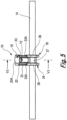
- the drawings show a connecting device 10 for connecting a flexible first elongate article 12, in the form of a first wire, cable, wire rope, tape or the like, transverse to a second elongate article 14.
- the second elongate article 14 may be a flexible elongate article in the form of a second wire, cable, wire rope, tape or the like.
- the second elongate article 14 may be a rigid elongate article, such as a rebar.
- the connecting device 10 is suitable for use in agriculture, particularly in the growing of fruit trees and vines. However, it will be appreciated that the connecting device 10 can be used in any industry.
- flexible first elongate articles 12 extend between rows of the trees or vines, and over the tops of the trees or vines along the rows.
- the first elongate articles 12 are joined to the second elongate articles 14 extending around the fields in which the vines or trees are grown.
- the netting is supported by the first and flexible second elongate articles 12, 14.
- the connecting device 10 comprises a first securing arrangement in the form of a first clamping arrangement 16.
- the first clamping arrangement 16 clamps the flexible first elongate article 12.
- the connecting device 10 further includes a second securing arrangement in the form of a second clamping arrangement 18.
- the second clamping arrangement 18 clamps the flexible second elongate article 14.
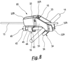
- the connecting device 10 comprises a body 20 in the form of a housing in which the first clamping arrangement 16 is housed.
- the body 20 has a forward region 20A and a rearward region 20B.
- the first clamping arrangement 16 comprises a clamping member 22 in the form of a wedge, roller or ball.
- the first clamping arrangement 16 further includes an urging member 24 in the form of a compression spring.
- the compression spring may have inwardly tapering opposite ends, each having a frustoconical configuration.
- the body 20 defines an internal space 26 in which the urging member 24 is disposed.
- the body 20 also defines a passage 28 for the first elongate article 12.
- the passage 28 has openings 28A and 28B at opposite ends of the body 20, and is configured to allow the first elongate article 12 to be threaded through the body 20 via the openings 28A, 28B.
- the space 26 is defined in the body 20 so that the urging member 24 urges the clamping member 22 towards the passage 28 to engage, and thereby clamp, the first elongate article 12.
- the passage 28 has a clamping surface 30 provided by the body 20.
- the first elongate article 12 extends through the passage 28 along the clamping surface 30, in engagement with the clamping surface 30.
- the urging member 24 is arranged between the passage 28 and the second clamping arrangement 18.
- the urging member 24 extends, from the forward region 20A of the body 20, to the clamping member 22 at the rearward region 20B of the body 20.
- the body 20 further provides a reaction surface 32 opposite the clamping surface 30.
- the reaction surface 32 is a surface defining the internal space 26, and extends obliquely to the clamping surface 30.
- the urging member 24 urges the clamping member 22 along the reaction surface 32.
- the gap between the reaction surface 32 and the clamping surface 30 narrows in the direction in which the urging member 24 urges the clamping member 22.
- the first elongate article 12 is clamped by the clamping member 22 between the clamping and reaction surfaces 30, 32.
- a nose formation in the form of a pair of projections 33 extend from the forward region 20A of the body 20.
- the projections 33 are parallel to each other and include narrowed forward end portions 33A to cooperate with a tensioning tool to allow the tensioning tool to tension the first elongate article 12 within the first clamping arrangement 16.
- the second clamping arrangement 18 comprises a receiving arrangement in the form of a hook formation 34 for receiving the second elongate article 14.
- the hook formation 34 comprises a pair of hook members 36 arranged side by side. Each hook member 36 is provided at the forward region 20A of the body 20, and extends from a respective one of the projections 33.
- Both of the hook members 36 face in the same direction relative to the body 20, i.e. towards the rearward region 20B of the body 20.
- a web portion 37 extends between the hook members 36 to join the hook members 36 to each other.
- the second clamping arrangement 18 further includes a movable member 38 in the form of a bolt.
- the movable member 38 has a proximal end region 40 comprising a head 42 comprising a drive formation 44 in the form of a hexagonal recess to cooperate with a driver in the form of a hex key (not shown).
- the driver may be any other suitable driver known in the art, such as a screwdriver or spanner, and the head may be suitably configured in a manner which would be known to the person skilled in the art.
- the movable member 38 further includes a threaded shaft 45.
- the second clamping arrangement 18 includes a holder 46 to hold the movable member 38.
- the holder 46 has threads that correspond with the threads on the shaft 45 of the moveable member 38, thereby allowing the movable member 38 to be screwed into the holder 46 in a direction towards the hook formation 34.
- each of the hook members 36 defines a gap 48 which faces the movable member 38.
- the second elongate article 14 is received by hook members 36 via the gaps 48.
- the movable member 38 further includes a distal end region 50 for engaging the second elongate article 14.
- the distal end region 50 constitutes a clamping portion of the movable member 38, and clamps the second elongate article 14 against the hook formation 34 when the movable member 38 is screwed into the holder 46.
- the tension on the first elongate article 12 does not cause the first elongate article 12 to be inadvertently released from the first clamping arrangement 16 when the second elongate article 14 is clamped by the second clamping arrangement 18.
- the clamping surface 30 and the reaction surface 32 taper towards each other in a direction away from the hook formation 34.
- the urging member 24 urges the clamping member 22 in a direction away from the hook formation 34.
- first elongate article 12 first secured to the connecting device 10 as follows.
- the first elongate article 12 is threaded into the passage 28 in the direction indicated by the arrow B in Figure 6 .
- the first elongate article 12 engages the clamping member 22 and pushes it against the urging of the urging member 24 along the reaction surface 32 in the direction indicated by the arrow C. This moves the clamping member 22 out of the way of the first elongate article 12, which can now be threaded into the passage 28 until a desired length has been threaded therethrough.
- the first elongate article 12 is then pulled in the direction indicated by the arrow A in Figure 6 .
- the first elongate article 12 is clamped by the clamping member 22 against the clamping surface 30, and held under tension by the connecting device 10 when the second elongate article 14 is clamped by the movable member 38 to the hook formation 34.
- the second elongate article 14 which may have already been installed in its desired location, is secured to the connecting device 10 as follows.
- the hook formation 34 is arranged over the second elongate article 14 so that the second elongate article 14 is received in the hook members 36 via the gaps 48.
- the movable member 38 is then screwed through the holder 46 until the distal end region 50 engages the second elongate article 14 in a region between the hook members 36.
- the movable member 38 is then tightened onto the second elongate article 14, pushing the second elongate article 14 into tight engagement with the hook formation 34.
- the second elongate article 14 is clamped to the connecting device 10.
- the first and second elongate articles 12, 14 are connected to each other in respective orientations that are transverse relative to each other. In the embodiment shown, the first and second elongate articles 14 are connected to each other at approximately 90°.
- connecting device 10 for connecting first and second elongate articles 14, such as wires or cables, to each other in orientations that are transverse to one another.
- the connecting device 10 is quick and simple to use and enables the first and second elongate articles 14 to be connected to each other securely and effectively.
- the pair of hook members 36 may be replaced by a single hook member extending across the body 20.
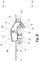
- FIG. 7 to 12 Another connecting device, generally designated 60, is shown in Figures 7 to 12 .
- the connecting device 60 comprises the features of the connecting device 10, such features being designated with the same reference numerals in Figures 7 to 12 as in Figures 1 to 6 .
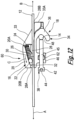
- the first clamping arrangement 16 of the connecting device 60 is arranged so that the passage is between the urging member and the second clamping arrangement. As shown in Figure 12 , the passage 28 is arranged between urging member 24 and the second clamping arrangement 18. The urging member 24 extends, from the forward region 20A of the body 20, to the clamping member 22, at the rearward region 20B of the body 20.
- the passage 28 is closer to the second clamping arrangement 18, which, in the embodiment described, improves alignment of the first elongate 12 with the second elongate article 14, and helps prevent rotation of the body 20.
- Such rotation of the body 20 may occur when the distance between the first and second elongate articles 12, 14 is large.
- the connecting device 60 shown in Figures 7 to 12 reduces loading on the body 20, thereby allowing the connecting device 60 to be lighter in weight, because less material is required. In addition, there is a reduction in the extent to which the body 20 tilts.
- the hook members 36 are arranged alongside each other, and extend contiguously adjacent each other; no web portion 37 is required in the connecting device 60 shown in Figures 7 to 12 .
- the projections 33A of the connecting device 60 are longer than the projections 33A of the connecting device 10, thereby improving interaction with the tensioning tool (not shown).
- the connecting device 60 includes a captive fastening member in the form of a threaded nut held by the body 20.
- the threaded nut receives the movable member 38 therethrough.
- the movable member 38 is held by the holder 46.
- connecting devices 10, 60 which reduce the time and difficulty associated with twisting and tying steel wire, thereby reducing the risk of hand injuries and allowing for a consistent and high quality tensioned join.
- the connecting devices 10, 60 are faster and less expensive to install (saving on labour costs), lighter and smaller to transport (saving on transportation costs) and easier to install as a single component system that joins and tensions in one.
- the connecting devices 10, 60 can be used with second elongate articles 14 of different sizes and diameters.
Landscapes
- Engineering & Computer Science (AREA)
- General Engineering & Computer Science (AREA)
- Mechanical Engineering (AREA)
- Life Sciences & Earth Sciences (AREA)
- Environmental Sciences (AREA)
- Botany (AREA)
- Clamps And Clips (AREA)
- Insulating Bodies (AREA)
- Handcart (AREA)
- Mutual Connection Of Rods And Tubes (AREA)
- Vehicle Interior And Exterior Ornaments, Soundproofing, And Insulation (AREA)
Claims (13)
- Verbindungsvorrichtung (10), die Folgendes umfasst:eine erste Befestigungsanordnung zum Befestigen eines ersten länglichen Gegenstands (12) an der Verbindungsvorrichtung (10) in einer ersten Ausrichtung des ersten länglichen Gegenstands (12);eine zweite Befestigungsanordnung zum Befestigen eines zweiten länglichen Gegenstands (14) an der Verbindungsvorrichtung (10) in einer zweiten Ausrichtung des zweiten länglichen Gegenstands (14);wobei die zweite Ausrichtung quer zur ersten Ausrichtung verläuft;einen Körper (20) zum Tragen der ersten und der zweiten Befestigungsanordnung, wobei der Körper (20) einen vorderen Bereich (20A) und einen hinteren Bereich (20B) aufweist;wobei die erste Befestigungsanordnung eine erste Klemmanordnung (16) und die zweite Befestigungsanordnung eine zweite Klemmanordnung (18) umfasst;die erste Klemmanordnung (16) einen Durchgang (28) für den ersten länglichen Gegenstand (12) umfasst, wobei der Durchgang (28) durch den Körper (20) eingegrenzt ist, und die erste Klemmanordnung (16) ein Klemmelement (22) und ein Druckelement (24) umfasst, wobei das Klemmelement (22) so angeordnet ist, dass es den ersten länglichen Gegenstand (12) in dem Durchgang (28) festklemmt;wobei die zweite Klemmanordnung (18) eine Aufnahmeanordnung (34) zum Aufnehmen des zweiten länglichen Gegenstands (14) umfasst und die zweite Klemmanordnung (18) ferner ein bewegliches Element (38) einschließt, wobei das bewegliche Element (38) einen Klemmabschnitt (50) zum Festklemmen des zweiten länglichen Gegenstands (14) einschließt und das bewegliche Element einen zusammenwirkenden Abschnitt (45) einschließt, um eine Bewegung des beweglichen Elements (38) zu ermöglichen, um den zweiten länglichen Gegenstand (14) gegen die Aufnahmeanordnung (34) zu klemmen, um den zweiten länglichen Gegenstand (14) an der zweiten Befestigungsanordnung (18) zu befestigen;dadurch gekennzeichnet, dass das Druckelement (24) so angeordnet ist, dass es das Klemmelement (22) zum Durchgang (28) hin in eine Richtung weg von dem vorderen Bereich (20A) des Körpers (20) in Klemmeingriff mit dem ersten länglichen Gegenstand (12) drückt, undferner dadurch gekennzeichnet, dass das bewegliche Element (38) beweglich ist, um den Klemmabschnitt (50) in eine Richtung weg von dem hinteren Bereich (20B) des Körpers (20) zu bewegen, um den zweiten länglichen Gegenstand (14) einzuklemmen.
- Verbindungsvorrichtung (10) nach Anspruch 1, wobei die Verbindungsvorrichtung (10) eine Nasenausbildung (33) aufweist, die sich von dem vorderen Bereich (20A) des Körpers (20) erstreckt, wobei die Nasenausbildung (33) ein Paar von im Wesentlichen parallelen Vorsprüngen aufweist, wobei ein Spalt durch die Nasenausbildung (33) zwischen den Vorsprüngen eingegrenzt ist.
- Verbindungsvorrichtung (10) nach Anspruch 1 oder 2, wobei der Körper (20) einen Innenraum (26) eingrenzt, in dem das Druckelement (24) angeordnet ist, wobei der Innenraum (26) mit dem Durchgang (28) in Verbindung steht, damit das Druckelement (24) das Klemmelement (22) in Richtung des Durchgangs (28) drücken kann.
- Verbindungsvorrichtung (10) nach Anspruch 1, 2 oder 3, wobei das Druckelement (24) das Klemmelement (22) in eine Richtung weg von der Aufnahmeanordnung (34) drückt.
- Verbindungsvorrichtung (10) nach einem der vorhergehenden Ansprüche, wobei die zweite Befestigungsanordnung eine Hakenausbildung (34) umfasst, die so eingerichtet ist, dass sie sich um den zweiten länglichen Gegenstand (14) herum erstreckt.
- Verbindungsvorrichtung (10) nach Anspruch 5, wobei die Hakenausbildung (34) umfasst:
entweder ein Paar nebeneinander angeordneter Hakenelemente (36), wobei jedes der Hakenelemente (36) eine dem hinteren Endbereich (20B) des Körpers (20) zugewandte Öffnung aufweist:
oder ein einzelnes Hakenelement, wobei das Hakenelement eine dem hinteren Endbereich (20B) des Körpers (20) zugewandte Öffnung aufweist. - Verbindungsvorrichtung (10) nach Anspruch 1, wobei:entweder der Körper (20) zusammenwirkende Ausbildungen aufweist, um mit dem zusammenwirkenden Abschnitt des beweglichen Elements (38) zusammenzuwirken, wodurch die oben erwähnte Bewegung des beweglichen Elements (38) bewirkt wird;oder die zweite Befestigungsanordnung ein einzelnes Befestigungselement aufweist, das von dem Körper (20) gehalten wird, wobei das Befestigungselement Ausbildungen umfasst, um mit dem zusammenwirkenden Abschnitt zusammenzuwirken, um die vorgenannte Bewegung zu bewirken.
- Verfahren zum Verwenden einer Verbindungsvorrichtung (10) nach Anspruch 1, wobei das Verfahren das Befestigen des ersten länglichen Gegenstands (12) an der Verbindungsvorrichtung (10) mit Hilfe der ersten Befestigungsanordnung und das Befestigen des zweiten länglichen Gegenstands (14) an der Verbindungsvorrichtung (10) mit Hilfe der zweiten Befestigungsanordnung umfasst;wobei der Schritt des Befestigens des ersten länglichen Gegenstands (12) an der ersten Befestigungsanordnung das Festklemmen des ersten länglichen Gegenstands (12) mittels der ersten Klemmanordnung (16) umfasst, und der Schritt des Befestigens des zweiten länglichen Gegenstands (14) an der zweiten Befestigungsanordnung das Festklemmen des zweiten länglichen Gegenstands (14) mittels der zweiten Klemmanordnung (18) umfasst;wobei der Schritt des Befestigens des ersten länglichen Gegenstandes (12) das Anordnen des ersten länglichen Gegenstandes (12) innerhalb des Durchgangs (28) umfasst, undwobei der Schritt des Befestigens des zweiten länglichen Gegenstandes (14) an der zweiten Befestigungsanordnung das Anordnen des zweiten länglichen Gegenstandes (14) in der Aufnahmeanordnung (34) umfasst.
- Verfahren nach Anspruch 8, wobei der Schritt des Befestigens des ersten länglichen Gegenstands (12) an der ersten Befestigungsanordnung das Bewegen des ersten länglichen Gegenstands (12) durch den Durchgang (28) umfasst, um das Klemmelement (22) vom Durchgang (28) weg zu bewegen, und danach das Bewegen des ersten länglichen Gegenstands (12) in die entgegengesetzte Richtung umfasst, um das Klemmelement (22) zu veranlassen, den ersten länglichen Gegenstand (12) einzuklemmen.
- Verfahren nach Anspruch 9, wobei die erste Klemmanordnung (16) eine Klemmfläche für den Eingriff mit dem ersten länglichen Gegenstand (12) aufweist und die erste Klemmanordnung (16) ferner eine Reaktionsfläche aufweist, um eine Reaktionskraft auf das Klemmelement (22) auszuüben, und wobei der Schritt des Festklemmens des ersten länglichen Gegenstands (12) das Anordnen des ersten länglichen Gegenstands (12) und des Klemmelements (22) zwischen der Klemmfläche und der Reaktionsfläche umfasst.
- Verfahren nach einem der Ansprüche 8 bis 10, wobei der Schritt des Befestigens des ersten länglichen Gegenstands (12) an der ersten Befestigungsanordnung das Halten des ersten länglichen Gegenstands (12) unter Spannung umfasst, wenn der zweite längliche Gegenstand (14) an der zweiten Befestigungsanordnung befestigt ist.
- Verfahren nach einem der Ansprüche 8 bis 11, wobei die Aufnahmeanordnung (34) eine Hakenausbildung (34) umfasst, wobei die Hakenausbildung (34) so eingerichtet ist, dass sie sich um den zweiten länglichen Gegenstand (14) erstreckt, und wobei der Schritt des Befestigens des zweiten länglichen Gegenstands (14) an der zweiten Befestigungsanordnung das Anordnen des zweiten länglichen Gegenstands (14) in der Hakenausbildung (34) umfasst.
- Verfahren nach Anspruch 12, wobei die zweite Befestigungsanordnung ein bewegliches Element (38) umfasst, wobei das bewegliche Element (38) einen Klemmabschnitt (50) zum Festklemmen des zweiten länglichen Gegenstands (14) enthält, und wobei der Schritt des Befestigens des zweiten länglichen Gegenstands (14) an der zweiten Befestigungsanordnung das Bewegen des beweglichen Elements (38) umfasst, um den zweiten länglichen Gegenstand (14) mit dem Klemmabschnitt (50) festzuklemmen.
Applications Claiming Priority (4)
| Application Number | Priority Date | Filing Date | Title |
|---|---|---|---|
| GBGB1813867.7A GB201813867D0 (en) | 2018-08-24 | 2018-08-24 | Connecting device |
| GBGB1906724.8A GB201906724D0 (en) | 2019-05-13 | 2019-05-13 | Connecting device |
| GB1910146.8A GB2577161B (en) | 2018-08-24 | 2019-07-16 | Connecting device |
| PCT/GB2019/000102 WO2020039153A1 (en) | 2018-08-24 | 2019-07-17 | Connecting device |
Publications (3)
| Publication Number | Publication Date |
|---|---|
| EP3841314A1 EP3841314A1 (de) | 2021-06-30 |
| EP3841314B1 true EP3841314B1 (de) | 2023-09-13 |
| EP3841314C0 EP3841314C0 (de) | 2023-09-13 |
Family
ID=67700185
Family Applications (1)
| Application Number | Title | Priority Date | Filing Date |
|---|---|---|---|
| EP19758436.0A Active EP3841314B1 (de) | 2018-08-24 | 2019-07-17 | Anschlussvorrichtung |
Country Status (13)
| Country | Link |
|---|---|
| US (1) | US11221056B2 (de) |
| EP (1) | EP3841314B1 (de) |
| JP (1) | JP7371086B2 (de) |
| CN (1) | CN112534157B (de) |
| AU (1) | AU2019323735A1 (de) |
| BR (1) | BR112021001306A2 (de) |
| CA (1) | CA3104405A1 (de) |
| CL (1) | CL2021000200A1 (de) |
| ES (1) | ES2964175T3 (de) |
| GB (1) | GB2577161B (de) |
| MX (1) | MX2021001105A (de) |
| WO (1) | WO2020039153A1 (de) |
| ZA (1) | ZA202100238B (de) |
Families Citing this family (3)
| Publication number | Priority date | Publication date | Assignee | Title |
|---|---|---|---|---|
| US11877540B2 (en) | 2018-11-14 | 2024-01-23 | Michael Bartrom | Tray and Trellis System for an Automated Farm with Robots Working on Plants |
| GB2610057A (en) * | 2021-07-19 | 2023-02-22 | Gripple Ltd | Suspension assembly |
| GB202213598D0 (en) * | 2022-09-16 | 2022-11-02 | Gripple Ltd | Improvements relating to hangers and hanger systems |
Family Cites Families (18)
| Publication number | Priority date | Publication date | Assignee | Title |
|---|---|---|---|---|
| JPH0339097Y2 (de) * | 1985-10-23 | 1991-08-16 | ||
| US4828210A (en) * | 1988-04-13 | 1989-05-09 | Alpha-M, Inc. | One-hand adjustable lock for tether |
| US7073754B2 (en) | 2002-02-28 | 2006-07-11 | Ductmate Industries, Inc. | Cable support systems |
| ITTO20030130A1 (it) | 2003-02-21 | 2004-08-22 | Petratto Srl | Morsetto per il collegamento di barre |
| GB2412284A (en) * | 2004-03-15 | 2005-09-28 | Dennis Ward | An adjustable plant support |
| US20070011851A1 (en) * | 2005-07-12 | 2007-01-18 | Chih-Hsin Wang | Rope device |
| ATE542972T1 (de) | 2007-02-08 | 2012-02-15 | Gripple Ltd | Drahtanschlussvorrichtung |
| FR2918555B1 (fr) * | 2007-07-12 | 2010-04-02 | Ldr Medical | Dispositif et systeme de liaison rachidienne transverse |
| GB0913082D0 (en) * | 2008-07-29 | 2009-09-02 | Gripple Ltd | Suspension device |
| JP5225872B2 (ja) | 2009-01-20 | 2013-07-03 | 大阪コートロープ株式会社 | 架線用吊金具 |
| CZ23927U1 (cs) * | 2012-04-24 | 2012-06-04 | Sybera@Stanislav | Posuvný hácek gumového lana k upevnení predmetu |
| CN202971741U (zh) * | 2012-12-25 | 2013-06-05 | 宁波市凹凸重工有限公司 | 安全绳固定装置 |
| DE202013007061U1 (de) * | 2013-08-07 | 2013-12-16 | Wilhelm Marke | Pflanzenhalter zur Befestigung an einem Stab oder Rohr |
| CN203702992U (zh) * | 2014-01-23 | 2014-07-09 | 宁波市鄞州五乡伟有机电配件厂 | 一种齿卡式连接器 |
| GB2535605B (en) * | 2014-12-23 | 2018-04-18 | Gripple Ltd | Clamping devices for retaining elongate members on support arrangements |
| CN204907336U (zh) * | 2015-06-09 | 2015-12-30 | 石泰龙 | 蔬菜支架 |
| CN204985510U (zh) * | 2015-09-25 | 2016-01-20 | 四川加力机电有限公司 | 一种软绳锁紧装置 |
| GB201705761D0 (en) * | 2017-04-10 | 2017-05-24 | Gripple Ltd | Securing arrangement |
-
2019
- 2019-07-16 GB GB1910146.8A patent/GB2577161B/en active Active
- 2019-07-17 CN CN201980050618.XA patent/CN112534157B/zh active Active
- 2019-07-17 ES ES19758436T patent/ES2964175T3/es active Active
- 2019-07-17 EP EP19758436.0A patent/EP3841314B1/de active Active
- 2019-07-17 MX MX2021001105A patent/MX2021001105A/es unknown
- 2019-07-17 JP JP2021504512A patent/JP7371086B2/ja active Active
- 2019-07-17 CA CA3104405A patent/CA3104405A1/en active Pending
- 2019-07-17 BR BR112021001306-7A patent/BR112021001306A2/pt unknown
- 2019-07-17 AU AU2019323735A patent/AU2019323735A1/en active Pending
- 2019-07-17 WO PCT/GB2019/000102 patent/WO2020039153A1/en unknown
- 2019-07-17 US US17/258,052 patent/US11221056B2/en active Active
-
2021
- 2021-01-13 ZA ZA2021/00238A patent/ZA202100238B/en unknown
- 2021-01-25 CL CL2021000200A patent/CL2021000200A1/es unknown
Also Published As
| Publication number | Publication date |
|---|---|
| GB2577161A (en) | 2020-03-18 |
| GB2577161B (en) | 2021-05-05 |
| BR112021001306A2 (pt) | 2021-04-27 |
| ZA202100238B (en) | 2022-07-27 |
| AU2019323735A1 (en) | 2021-01-14 |
| MX2021001105A (es) | 2021-03-31 |
| CN112534157A (zh) | 2021-03-19 |
| CN112534157B (zh) | 2023-10-13 |
| JP7371086B2 (ja) | 2023-10-30 |
| EP3841314C0 (de) | 2023-09-13 |
| JP2021534352A (ja) | 2021-12-09 |
| ES2964175T3 (es) | 2024-04-04 |
| CL2021000200A1 (es) | 2021-07-02 |
| WO2020039153A1 (en) | 2020-02-27 |
| US20210285515A1 (en) | 2021-09-16 |
| EP3841314A1 (de) | 2021-06-30 |
| US11221056B2 (en) | 2022-01-11 |
| GB201910146D0 (en) | 2019-08-28 |
| CA3104405A1 (en) | 2020-02-27 |
Similar Documents
| Publication | Publication Date | Title |
|---|---|---|
| EP3841314B1 (de) | Anschlussvorrichtung | |
| CN108457938B (zh) | 可调节的p型夹具 | |
| EP3324502B1 (de) | Wiegenklemmhalterungsanordnung | |
| US6533226B2 (en) | Saddle mount | |
| US8028962B2 (en) | Fir tree mount for cable ties | |
| US4930193A (en) | Cable retaining apparatus | |
| US20150267844A1 (en) | Cable lacing tie devices and methods of using the same | |
| US5632457A (en) | Adjustable routing clamp assembly | |
| CA2240367A1 (en) | Rope clamp | |
| CA2224363A1 (en) | Rope clamp | |
| US7076845B2 (en) | Mechanical knot apparatus | |
| US4860979A (en) | Adjustable fastening strap | |
| US20140008591A1 (en) | Apparatus for applying tension to flexible items | |
| EP3237777B1 (de) | Verbesserungen an oder im zusammenhang mit klemmvorrichtungen | |
| US7406751B2 (en) | Line tensioning systems and methods | |
| CN117262477A (zh) | 双向扣头扎带 | |
| EP0442997B1 (de) | Gerät zum anziehen von seilen | |
| CN113056187A (zh) | 连接组件以及用在连接组件中的紧固装置 | |
| AU624531B2 (en) | Rope tightening device | |
| EP3228880A1 (de) | Tannenbaumhalterung | |
| AU2009238334A1 (en) | Rope tensioning device |
Legal Events
| Date | Code | Title | Description |
|---|---|---|---|
| STAA | Information on the status of an ep patent application or granted ep patent |
Free format text: STATUS: UNKNOWN |
|
| STAA | Information on the status of an ep patent application or granted ep patent |
Free format text: STATUS: THE INTERNATIONAL PUBLICATION HAS BEEN MADE |
|
| STAA | Information on the status of an ep patent application or granted ep patent |
Free format text: STATUS: THE INTERNATIONAL PUBLICATION HAS BEEN MADE |
|
| PUAI | Public reference made under article 153(3) epc to a published international application that has entered the european phase |
Free format text: ORIGINAL CODE: 0009012 |
|
| STAA | Information on the status of an ep patent application or granted ep patent |
Free format text: STATUS: REQUEST FOR EXAMINATION WAS MADE |
|
| 17P | Request for examination filed |
Effective date: 20210309 |
|
| AK | Designated contracting states |
Kind code of ref document: A1 Designated state(s): AL AT BE BG CH CY CZ DE DK EE ES FI FR GB GR HR HU IE IS IT LI LT LU LV MC MK MT NL NO PL PT RO RS SE SI SK SM TR |
|
| DAV | Request for validation of the european patent (deleted) | ||
| DAX | Request for extension of the european patent (deleted) | ||
| GRAP | Despatch of communication of intention to grant a patent |
Free format text: ORIGINAL CODE: EPIDOSNIGR1 |
|
| STAA | Information on the status of an ep patent application or granted ep patent |
Free format text: STATUS: GRANT OF PATENT IS INTENDED |
|
| INTG | Intention to grant announced |
Effective date: 20230622 |
|
| GRAS | Grant fee paid |
Free format text: ORIGINAL CODE: EPIDOSNIGR3 |
|
| GRAA | (expected) grant |
Free format text: ORIGINAL CODE: 0009210 |
|
| STAA | Information on the status of an ep patent application or granted ep patent |
Free format text: STATUS: THE PATENT HAS BEEN GRANTED |
|
| AK | Designated contracting states |
Kind code of ref document: B1 Designated state(s): AL AT BE BG CH CY CZ DE DK EE ES FI FR GB GR HR HU IE IS IT LI LT LU LV MC MK MT NL NO PL PT RO RS SE SI SK SM TR |
|
| REG | Reference to a national code |
Ref country code: CH Ref legal event code: EP |
|
| REG | Reference to a national code |
Ref country code: DE Ref legal event code: R096 Ref document number: 602019037394 Country of ref document: DE |
|
| REG | Reference to a national code |
Ref country code: IE Ref legal event code: FG4D |
|
| U01 | Request for unitary effect filed |
Effective date: 20230925 |
|
| U07 | Unitary effect registered |
Designated state(s): AT BE BG DE DK EE FI FR IT LT LU LV MT NL PT SE SI Effective date: 20230929 |
|
| PG25 | Lapsed in a contracting state [announced via postgrant information from national office to epo] |
Ref country code: GR Free format text: LAPSE BECAUSE OF FAILURE TO SUBMIT A TRANSLATION OF THE DESCRIPTION OR TO PAY THE FEE WITHIN THE PRESCRIBED TIME-LIMIT Effective date: 20231214 |
|
| PG25 | Lapsed in a contracting state [announced via postgrant information from national office to epo] |
Ref country code: RS Free format text: LAPSE BECAUSE OF FAILURE TO SUBMIT A TRANSLATION OF THE DESCRIPTION OR TO PAY THE FEE WITHIN THE PRESCRIBED TIME-LIMIT Effective date: 20230913 Ref country code: NO Free format text: LAPSE BECAUSE OF FAILURE TO SUBMIT A TRANSLATION OF THE DESCRIPTION OR TO PAY THE FEE WITHIN THE PRESCRIBED TIME-LIMIT Effective date: 20231213 Ref country code: HR Free format text: LAPSE BECAUSE OF FAILURE TO SUBMIT A TRANSLATION OF THE DESCRIPTION OR TO PAY THE FEE WITHIN THE PRESCRIBED TIME-LIMIT Effective date: 20230913 Ref country code: GR Free format text: LAPSE BECAUSE OF FAILURE TO SUBMIT A TRANSLATION OF THE DESCRIPTION OR TO PAY THE FEE WITHIN THE PRESCRIBED TIME-LIMIT Effective date: 20231214 |
|
| REG | Reference to a national code |
Ref country code: ES Ref legal event code: FG2A Ref document number: 2964175 Country of ref document: ES Kind code of ref document: T3 Effective date: 20240404 |
|
| PG25 | Lapsed in a contracting state [announced via postgrant information from national office to epo] |
Ref country code: IS Free format text: LAPSE BECAUSE OF FAILURE TO SUBMIT A TRANSLATION OF THE DESCRIPTION OR TO PAY THE FEE WITHIN THE PRESCRIBED TIME-LIMIT Effective date: 20240113 |
|
| PG25 | Lapsed in a contracting state [announced via postgrant information from national office to epo] |
Ref country code: SM Free format text: LAPSE BECAUSE OF FAILURE TO SUBMIT A TRANSLATION OF THE DESCRIPTION OR TO PAY THE FEE WITHIN THE PRESCRIBED TIME-LIMIT Effective date: 20230913 Ref country code: RO Free format text: LAPSE BECAUSE OF FAILURE TO SUBMIT A TRANSLATION OF THE DESCRIPTION OR TO PAY THE FEE WITHIN THE PRESCRIBED TIME-LIMIT Effective date: 20230913 Ref country code: IS Free format text: LAPSE BECAUSE OF FAILURE TO SUBMIT A TRANSLATION OF THE DESCRIPTION OR TO PAY THE FEE WITHIN THE PRESCRIBED TIME-LIMIT Effective date: 20240113 Ref country code: CZ Free format text: LAPSE BECAUSE OF FAILURE TO SUBMIT A TRANSLATION OF THE DESCRIPTION OR TO PAY THE FEE WITHIN THE PRESCRIBED TIME-LIMIT Effective date: 20230913 Ref country code: SK Free format text: LAPSE BECAUSE OF FAILURE TO SUBMIT A TRANSLATION OF THE DESCRIPTION OR TO PAY THE FEE WITHIN THE PRESCRIBED TIME-LIMIT Effective date: 20230913 |