EP3840400B1 - Kompressionstreiber - Google Patents
Kompressionstreiber Download PDFInfo
- Publication number
- EP3840400B1 EP3840400B1 EP20213452.4A EP20213452A EP3840400B1 EP 3840400 B1 EP3840400 B1 EP 3840400B1 EP 20213452 A EP20213452 A EP 20213452A EP 3840400 B1 EP3840400 B1 EP 3840400B1
- Authority
- EP
- European Patent Office
- Prior art keywords
- acoustic
- compression driver
- duct
- connection duct
- chamber
- Prior art date
- Legal status (The legal status is an assumption and is not a legal conclusion. Google has not performed a legal analysis and makes no representation as to the accuracy of the status listed.)
- Active
Links
Images


Classifications
-
- H—ELECTRICITY
- H04—ELECTRIC COMMUNICATION TECHNIQUE
- H04R—LOUDSPEAKERS, MICROPHONES, GRAMOPHONE PICK-UPS OR LIKE ACOUSTIC ELECTROMECHANICAL TRANSDUCERS; ELECTRIC HEARING AIDS; PUBLIC ADDRESS SYSTEMS
- H04R1/00—Details of transducers, loudspeakers or microphones
- H04R1/20—Arrangements for obtaining desired frequency or directional characteristics
- H04R1/22—Arrangements for obtaining desired frequency or directional characteristics for obtaining desired frequency characteristic only
- H04R1/30—Combinations of transducers with horns, e.g. with mechanical matching means, i.e. front-loaded horns
-
- H—ELECTRICITY
- H04—ELECTRIC COMMUNICATION TECHNIQUE
- H04R—LOUDSPEAKERS, MICROPHONES, GRAMOPHONE PICK-UPS OR LIKE ACOUSTIC ELECTROMECHANICAL TRANSDUCERS; ELECTRIC HEARING AIDS; PUBLIC ADDRESS SYSTEMS
- H04R9/00—Transducers of moving-coil, moving-strip, or moving-wire type
- H04R9/06—Loudspeakers
-
- G—PHYSICS
- G10—MUSICAL INSTRUMENTS; ACOUSTICS
- G10K—SOUND-PRODUCING DEVICES; METHODS OR DEVICES FOR PROTECTING AGAINST, OR FOR DAMPING, NOISE OR OTHER ACOUSTIC WAVES IN GENERAL; ACOUSTICS NOT OTHERWISE PROVIDED FOR
- G10K9/00—Devices in which sound is produced by vibrating a diaphragm or analogous element, e.g. fog horns, vehicle hooters or buzzers
- G10K9/12—Devices in which sound is produced by vibrating a diaphragm or analogous element, e.g. fog horns, vehicle hooters or buzzers electrically operated
- G10K9/13—Devices in which sound is produced by vibrating a diaphragm or analogous element, e.g. fog horns, vehicle hooters or buzzers electrically operated using electromagnetic driving means
-
- H—ELECTRICITY
- H04—ELECTRIC COMMUNICATION TECHNIQUE
- H04R—LOUDSPEAKERS, MICROPHONES, GRAMOPHONE PICK-UPS OR LIKE ACOUSTIC ELECTROMECHANICAL TRANSDUCERS; ELECTRIC HEARING AIDS; PUBLIC ADDRESS SYSTEMS
- H04R1/00—Details of transducers, loudspeakers or microphones
- H04R1/20—Arrangements for obtaining desired frequency or directional characteristics
- H04R1/32—Arrangements for obtaining desired frequency or directional characteristics for obtaining desired directional characteristic only
- H04R1/34—Arrangements for obtaining desired frequency or directional characteristics for obtaining desired directional characteristic only by using a single transducer with sound reflecting, diffracting, directing or guiding means
- H04R1/345—Arrangements for obtaining desired frequency or directional characteristics for obtaining desired directional characteristic only by using a single transducer with sound reflecting, diffracting, directing or guiding means for loudspeakers
- H04R1/347—Arrangements for obtaining desired frequency or directional characteristics for obtaining desired directional characteristic only by using a single transducer with sound reflecting, diffracting, directing or guiding means for loudspeakers for obtaining a phase-shift between the front and back acoustic wave
-
- H—ELECTRICITY
- H04—ELECTRIC COMMUNICATION TECHNIQUE
- H04R—LOUDSPEAKERS, MICROPHONES, GRAMOPHONE PICK-UPS OR LIKE ACOUSTIC ELECTROMECHANICAL TRANSDUCERS; ELECTRIC HEARING AIDS; PUBLIC ADDRESS SYSTEMS
- H04R9/00—Transducers of moving-coil, moving-strip, or moving-wire type
- H04R9/02—Details
-
- H—ELECTRICITY
- H04—ELECTRIC COMMUNICATION TECHNIQUE
- H04R—LOUDSPEAKERS, MICROPHONES, GRAMOPHONE PICK-UPS OR LIKE ACOUSTIC ELECTROMECHANICAL TRANSDUCERS; ELECTRIC HEARING AIDS; PUBLIC ADDRESS SYSTEMS
- H04R2400/00—Loudspeakers
- H04R2400/13—Use or details of compression drivers
-
- H—ELECTRICITY
- H04—ELECTRIC COMMUNICATION TECHNIQUE
- H04R—LOUDSPEAKERS, MICROPHONES, GRAMOPHONE PICK-UPS OR LIKE ACOUSTIC ELECTROMECHANICAL TRANSDUCERS; ELECTRIC HEARING AIDS; PUBLIC ADDRESS SYSTEMS
- H04R9/00—Transducers of moving-coil, moving-strip, or moving-wire type
- H04R9/02—Details
- H04R9/025—Magnetic circuit
Definitions
- the present invention relates to the technical field of audio reproduction systems, and in particular it is directed to a compression driver.
- An electro-acoustic transducer is an audio system device adapted to convert an electrical signal into acoustic waves.
- a particular type of known acoustic transducers comprise at least one sound source in audio band such as, for example a compression driver, and an acoustic waveguide, called horn.
- the horn comprises an internally hollow main body which extends between an inlet opening adapted to receive an acoustic radiation and an outlet opening for diffusing said acoustic radiation outside the horn.
- the main body has inner walls which delimit a tapered duct allowing the propagation of the acoustic radiation between the inlet opening and the outlet opening.
- the inlet opening generally is called throat of the horn, while the outlet opening generally is called mouth of the horn.
- At least one compression driver may be fastened to the throat of the horn in certain acoustic transducers.
- An example of compression driver of the known art is described in Patent EP 2 640 089 B1 .
- a compression driver generally comprises a housing which houses at least one vibrating membrane having two opposite faces. One of the two faces of the vibrating membrane is facing a compression chamber communicating with at least one acoustic outlet duct. Such at least one acoustic outlet duct conducts the acoustic waves generated by the movement of the vibrating membrane up to the outlet port of the compression driver and therefore, up to the horn inlet, i.e., up to the throat of the horn.
- a movable coil fed by with electrical signal is fastened to the vibrating membrane.
- the compression driver further comprises a magnetic assembly having an air gap inside which the movable coil is free to move.
- the other of the two faces of the vibrating membrane closes a further chamber opposite to the compression chamber and which in fact, is a second compression chamber.
- the air closed inside the second compression chamber is compressed and decompressed due to the movement of the vibrating membrane, due to the movement of the coil.
- the air contained in the second compression chamber opposes a certain resistance to the movement of the vibrating membrane, which restricts the low frequency response of the compression driver.
- the rigidity of the suspensions of the vibrating membrane is reduced to extend the low frequency response in compression drivers. However, this may not be sufficient or may not be possible due to design constraints.
- Document WO 2014/081092 A1 describes a driver having a complex and bulky structure because it requires an outer cover, having a front cover and a rear cover, and an inner cover. An acoustic connection duct at least partly extends between the inner cover and the outer cover.
- a driver having just as complex and bulky a structure is also described in document JP 2016 082369 A .
- Figure 1 shows a non-limiting embodiment of an electro-acoustic transducer 1.
- the electro-acoustic transducer 1 comprises a compression driver 100 and a horn 2, which are operatively connected to each other, for example by means of a mechanical coupling system.
- horn 2 is mechanically coupled to the compression driver 100 by means of a coupling flange 5 and an associated screw system 6.
- Horn 2 has an internally hollow main body which extends between an inlet opening 3 adapted to receive an acoustic radiation in audio band emitted by the compression driver 100, and an opposite outlet opening 4 for diffusing such an acoustic radiation outside horn 2.
- the inlet opening 3 generally is called throat of horn 2, while the outlet opening 4 generally is called mouth of horn 2.
- the main body of horn 2 has walls which delimit a tapered duct allowing the propagation of the emitted acoustic radiation between the inlet opening 3 and the outlet opening 4, i.e., between the throat and the mouth.
- the outlet opening 4 is quadrangular in shape, rectangular in the example.
- the main body of horn 2 may be made of a plastic or metal material, e.g., of aluminum.
- the compression driver 100 comprises an acoustic outlet duct 101 which is adapted and configured to be coupled to the throat 3 of horn 2.
- an acoustic duct 101 preferably is a tapered duct, in particular a duct which cross section progressively widens in the direction approaching the throat 3 of horn 2.
- the acoustic outlet duct 101 is preferably delimited by a side wall 115.
- the compression driver 100 further comprises a magnetic assembly 102, 103, 104, or magnetic motor, comprising a permanent magnet 103 and an air gap 106.
- the permanent magnet 103 has an annular shape and therefore is provided with a central through hole.
- the magnetic assembly 102, 103, 104 comprises a ferromagnetic structure 102, 104.
- the compression driver 100 comprises a cap 105 fastened to the magnetic assembly 102, 103, 104.
- Cap 105 is preferably made of plastic or metal material, for example it is made of hard plastic or aluminum.
- the compression driver 100 further comprises a vibrating membrane 107 comprising a movable coil 108 adapted and configured to move inside the air gap 106.
- the movable coil 108 has a coil axis Z-Z.
- the movable coil 108 is fed with an electrical signal, it is configured to move axially, i.e., along the coil axis Z-Z, with respect to the magnetic assembly 102, 103, 104 and to vibrate the vibrating membrane 107.
- Axis Z-Z shown in the accompanying drawings is also the axis of the acoustic outlet duct 101.
- the vibrating membrane 107 is an annular membrane and is fastened to a radially outer support ring 112 and a radially inner support ring 113.
- the compression driver 100 preferably is a driver for medium-high frequencies and has, for example without introducing any limitation, a frequency response equal to 1 kHz to 20 kHz.
- the vibrating membrane 107 comprises a first face 107a facing a first chamber 110a communicating with the outlet duct 101.
- the first chamber 110a is a compression chamber.
- the vibrating membrane 107 further comprises a second face 107b opposite to the first face 107a and facing a second chamber 110b communicating with the air gap 106 and opposite to the first chamber 110a.
- the first chamber 110a and the second chamber 110b are conveniently arranged so that if the volume of one of the two chambers expands due to the vibration of membrane 107, the volume of the other chamber contracts, and vice versa. This clarifies the meaning of the term "opposite" used in the preceding paragraph in relation to the first chamber 110a and to the second chamber 110b.
- the compression driver 100 comprises at least one acoustic connection duct 111 that puts in communication the second chamber 110b with the acoustic outlet duct 101. It has been noted that the presence of the aforesaid acoustic connection duct 111 actually allows to extend the low frequency response of the compression driver 100.
- the acoustic connection duct 111 extends between an inlet opening which faces into the second chamber 110b and an outlet opening which faces into the acoustic outlet duct 101. More preferably, such an acoustic duct 111 is an entirely rectilinear duct for matters of increased production simplicity.
- the outlet opening of the acoustic connection duct 111 is defined on the side wall 115 of the acoustic outlet duct 101.
- the at least one acoustic connection duct 111 entirely extends into the thickness of the magnetic assembly 102, 103, 104.
- the at least one acoustic connection duct 111 extends along the whole length thereof into the thickness of the magnetic assembly 102, 103, 104.
- the acoustic connection duct 111 extends into a space which does not exceed the axial volume H of the magnetic assembly.
- the at least one acoustic connection duct 111 is a hole, preferably having circular cross section, defined in the magnetic assembly 102, 103, 104.
- the aforesaid acoustic connection duct 111 and the second compression chamber 110b serve as, i.e., define a, Helmholtz resonator.
- a Helmholtz resonator has a resonance frequency calculated so as to agree with the volume of the second chamber 110b, the force factor BL and the rigidity of the vibrating membrane 107 so that the whole system operates harmoniously as a single system in order to avoid phase shifts between the acoustic waves encountering one another in the acoustic outlet duct 111 from the first face 107a and from the second face 107b, respectively, of the vibrating membrane 107.
- a vibrating membrane mounted in a closed structure which is such as to define a rear compression chamber in the case of a compression driver of the known art, has a frequency response with a behavior of high-pass filter in low frequency.
- the introduction of at least one connection duct 111 allows to extend lower the lower frequency of the frequency response at the cost of a rising of the order of the filter.
- the preselected tuning determines the combined specifications of four parameters: resonance frequency of the mechanical part f s (determined by the mechanical suspensions and by the movable mass), speaker volume V B (which is an additional pneumatic suspension and which here, is equal to the volume of the second chamber 110b), loss ratio Q T (mechanical and electrical, whereby also dependent on the motor and the movable coil Bl 2 /R E ) and additional resonance frequency f H generated by the acoustic connection duct 111.
- the disclosure described particularly refers to a direct radiation speaker, in which the speaker and the system of the connection duct 111 are essentially subjected to the same external acoustic load.
- the strategy described may similarly be applied to manipulate the low frequency response of a compression driver.
- the magnetic assembly 102, 103, 104 comprises a ferromagnetic structure having a first ferromagnetic plate 102 and a second ferromagnetic plate 104 between which the permanent magnet 103 is interposed and said at least one acoustic connection duct 111 extends into the first ferromagnetic plate 102 or into the second ferromagnetic plate 104.
- this does not exclude embodiments in which the acoustic connection duct 111 extends into the permanent magnet 103.
- the acoustic connection duct 111 may extend, preferably entirely, into the pole piece 109.
- the acoustic connection duct 111 may be made in a convenient manner by perforating the pole piece 109, for example by means of a cutter or drill.
- the permanent magnet 103 has a through hole and the pole piece 109 is shaped so as to be inserted in the through hole.
- the pole piece 109 has a central hole which is coaxial with the outlet duct 101, and the acoustic connection duct 111 laterally extends into the pole piece 109, i.e., radially or transversely, with respect to the central hole.
- the acoustic connection duct 111 extends radially with respect to axis Z-Z of the movable coil 108, which is also the axis of the acoustic outlet duct 101.
- the acoustic connection duct 111 solely extends, i.e., over the whole length thereof, radially or transversely with respect to axis Z-Z of the movable coil 108.
- the compression driver 100 comprises two acoustic connection ducts 111.
- the number of acoustic ducts can be equal to one or even greater than two.
- the acoustic connection duct 111 has a circular cross section.
- a circular cross section may be constant along the whole acoustic connection duct 111 or variable along at least one segment of the acoustic connection duct 111.
- the compression driver 100 comprises a connecting duct 119 operatively interposed between the compression chamber 110a and the acoustic outlet duct 101.
- a connecting duct 119 preferably is also such as to deflect the generated acoustic radiation outlet from the first compression chamber 110a by 180°, or about 180°, in other words, such a duct is a U-shaped or substantially U-shaped connection.
- the aforesaid connecting duct 119 has an increasing cross section in the direction from the first chamber 110a to the acoustic outlet duct 101.
- such a duct 119 is a connecting and expansion duct.
- the aforesaid connecting duct 119 is preferably defined inside cap 105, and more preferably has a circular symmetry about axis Z-Z of the movable coil 108.
- the compression driver 101 comprises an ogive 120 housed in the acoustic outlet duct 101.
- the ogive 120 preferably is a conical element having cylindrical symmetry, and for example is fastened to cap 105, made for example in a single piece with the latter.
- the acoustic outlet duct 101 is preferably radially delimited in the outer wall of the ogive 120 and is radially delimited outside the side wall 115.
- Figure 5 shows a second embodiment of a compression driver 100 which differs from the embodiment in Figures 3 and 4 substantially in that the compression driver 100 therein has a dome-shaped vibrating membrane 107.
- the compression driver 101 does not have the ogive 120 and instead is provided with an acoustic equalizer 130.
- the first compression chamber 110a is defined between the first face 107a of the vibrating membrane 107 and the lower face of the acoustic equalizer 130.
- the second chamber 110b is formed by two chamber portions, of which a first portion is defined between the second face 107b of the vibrating membrane 107 and cap 105, and the second portion is defined in the ferromagnetic structure 102, 104, and in particular in the first ferromagnetic plate 102.
- the two chamber portions fluidically communicate with each other through the air gap 106.
- connection ducts 111 are provided, only by mere way of example.
- Figure 6 shows a third embodiment of a compression driver 100 which differs from the embodiment in Figure 5 substantially in that the compression driver 100 therein comprises acoustic connection ducts 111 which have a variable, preferably circular, cross section.
- the aforesaid cross section is particularly progressively decreasing in the direction from the second compression chamber 110b to the acoustic outlet duct 101.
- two diametrically-opposite acoustic connection ducts 111 are provided, only by mere way of example.
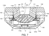
- Figure 7 shows a fourth embodiment of a compression driver 100 which differs from the embodiments in Figures 5 and 6 substantially in that the compression driver 100 therein comprises acoustic connection ducts 111, each of which longitudinally extends along a respective axis which is tilted with respect to axis Z-Z of the movable coil 108, for example tilted by about 45° with respect to axis Z-Z.
- the acoustic ducts instead extend along respective axes which are perpendicular to axis Z-Z of the movable coil 108.
- two diametrically-opposite acoustic connection ducts 111 are provided, only by mere way of example.
- acoustic connection duct 111 extends into the ferromagnetic structure 102, 104, this contrivance, albeit advantageous and preferred, is not essential or limiting. As mentioned above, embodiments are indeed possible in which the acoustic connection duct 111 extends into the permanent magnet 103. Moreover, it should be noted that it is not essential for the acoustic connection duct 111 to be rectilinear, because it could, for example be curved or "L"-shaped, etc.
- a compression driver 100 of the type described above allows to fully achieve the preset objects in terms of overcoming the drawbacks of the prior art. Indeed, by virtue of the presence of at least one acoustic connection duct 111, it has indeed been noted that excellent results are obtained in terms of low frequency extension of the frequency response of the compression driver 100.
Landscapes
- Physics & Mathematics (AREA)
- Engineering & Computer Science (AREA)
- Acoustics & Sound (AREA)
- Signal Processing (AREA)
- Health & Medical Sciences (AREA)
- Otolaryngology (AREA)
- Electromagnetism (AREA)
- Multimedia (AREA)
- Audible-Bandwidth Dynamoelectric Transducers Other Than Pickups (AREA)
- Apparatuses For Generation Of Mechanical Vibrations (AREA)
- Reciprocating Pumps (AREA)
Claims (15)
- Kompressionstreiber (100), umfassend:- einen akustischen Ausgangskanal (101);- eine Magnetanordnung (102, 103, 104), die einen Permanentmagneten (103) und einen Luftspalt (106) umfasst;- eine vibrierende Membran (107), die eine bewegliche Spule (108) umfasst, die zum Bewegen innerhalb des Luftspalts (106) geeignet und konfiguriert ist, wobei die bewegliche Spule (108) eine Spulenachse (Z-Z) aufweist, wobei die Spulenachse auch die Achse des akustischen Ausgangskanals (101) ist;wobei die vibrierende Membran (107) umfasst:- eine erste Fläche (107a), die einer ersten Kammer (110a) zugewandt ist, die mit dem Ausgangskanal (101) in Kommunikation steht, wobei die erste Kammer (110a) eine Kompressionskammer ist;- eine zweite Fläche (108a), die der ersten Fläche (107a) gegenüberliegt und einer zweiten Kammer (110b) zugewandt ist, die mit dem Luftspalt (106) in Kommunikation steht und der ersten Kammer (110a) gegenüberliegt;- mindestens einen akustischen Verbindungskanal (111), der die zweite Kammer (110b) mit dem akustischen Ausgangskanal (101) in Kommunikation bringt, wobei sich der mindestens eine akustische Verbindungskanal (111) zwischen einer Eingangsöffnung, die in die zweite Kammer (110b) weist, und einer Ausgangsöffnung, die in den akustischen Ausgangskanal (101) weist, erstreckt;dadurch gekennzeichnet, dass sich der mindestens eine akustische Verbindungskanal (111) vollständig in die Dicke der Magnetanordnung (102, 103, 104) erstreckt.
- Kompressionstreiber (100) nach Anspruch 1, wobei der akustische Ausgangskanal (101) durch eine Seitenwand (115) begrenzt ist und wobei die Ausgangsöffnung des akustischen Verbindungskanals (111) an der Seitenwand (115) des akustischen Ausgangskanals (101) definiert ist.
- Kompressionstreiber (100) nach Anspruch 1 oder 2, wobei sich der mindestens eine akustische Verbindungskanal (111) über die gesamte Länge davon in die Dicke der Magnetanordnung (102, 103, 104) erstreckt.
- Kompressionstreiber (100) nach einem der vorhergehenden Ansprüche, wobei die Magnetanordnung (102, 103, 104) eine ferromagnetische Konstruktion mit einer ersten ferromagnetischen Platte (102) und einer zweiten ferromagnetischen Platte (104), zwischen denen der Permanentmagnet (103) angeordnet ist, umfasst und wobei sich der mindestens eine akustische Verbindungskanal (111) in die erste ferromagnetische Platte (102) oder in die zweite ferromagnetische Platte (104) oder in den Permanentmagneten (103) erstreckt.
- Kompressionstreiber (100) nach Anspruch 4, wobei die erste ferromagnetische Platte (102) ein Polstück (109) mit einem Mittenloch umfasst, das koaxial zum Ausgangskanal (101) ist, und wobei sich der akustische Verbindungskanal (111) lateral in das Polstück (109) erstreckt, d. h. radial oder quer, in Bezug auf das Mittenloch.
- Kompressionstreiber (100) nach Anspruch 5, wobei der Permanentmagnet (103) ein Durchgangsloch aufweist und wobei das Polstück (109) derart geformt ist, dass es in das Durchgangsloch eingesetzt werden kann.
- Kompressionstreiber (100) nach einem der vorhergehenden Ansprüche, wobei sich der mindestens eine akustische Verbindungskanal (111) radial in Bezug auf die Spulenachse (Z-Z) erstreckt.
- Kompressionstreiber nach Anspruch 7, wobei sich der mindestens eine akustische Verbindungskanal (111) nur radial oder quer zur Spulenachse (Z-Z) erstreckt.
- Kompressionstreiber (100) nach einem der vorhergehenden Ansprüche, wobei der mindestens eine akustische Verbindungskanal (111) eine Vielzahl von akustischen Verbindungskanälen umfasst.
- Kompressionstreiber (100) nach einem der vorhergehenden Ansprüche, wobei der akustische Verbindungskanal (11) einen kreisförmigen Querschnitt aufweist.
- Kompressionstreiber (100) nach Anspruch 10, wobei sich der kreisförmige Querschnitt entlang mindestens eines Segments des akustischen Verbindungskanals (11) ändert.
- Kompressionstreiber (100) nach einem der vorhergehenden Ansprüche, wobei der akustische Verbindungskanal (11) vollständig geradlinig ist.
- Kompressionstreiber (100) nach einem der vorhergehenden Ansprüche, wobei der akustische Verbindungskanal (111) und die zweite Kammer (110b) einen Helmholtz-Resonator definieren.
- Kompressionstreiber (100) nach Anspruch 13, wobei der Helmholtz-Resonator eine Resonanzfrequenz fH aufweist, die durch die folgende Formel definiert ist:
 - c die Schallgeschwindigkeit ist;- l die Länge des akustischen Verbindungskanals (111) ist;- A der Querschnitt des akustischen Verbindungskanals (111) ist;- V B das Volumen der zweiten Kompressionskammer (110b) ist.
 - Elektroakustischer Wandler (1), umfassend ein Horn (2) und dadurch gekennzeichnet, dass er einen Kompressionstreiber (100) nach einem der vorhergehenden Ansprüche umfasst, der wirksam mit dem Horn (2) gekoppelt ist.
Applications Claiming Priority (1)
| Application Number | Priority Date | Filing Date | Title |
|---|---|---|---|
| IT102019000024799A IT201900024799A1 (it) | 2019-12-19 | 2019-12-19 | Driver a compressione |
Publications (3)
| Publication Number | Publication Date |
|---|---|
| EP3840400A1 EP3840400A1 (de) | 2021-06-23 |
| EP3840400B1 true EP3840400B1 (de) | 2023-10-11 |
| EP3840400C0 EP3840400C0 (de) | 2023-10-11 |
Family
ID=70228491
Family Applications (1)
| Application Number | Title | Priority Date | Filing Date |
|---|---|---|---|
| EP20213452.4A Active EP3840400B1 (de) | 2019-12-19 | 2020-12-11 | Kompressionstreiber |
Country Status (5)
| Country | Link |
|---|---|
| US (1) | US11336993B2 (de) |
| EP (1) | EP3840400B1 (de) |
| CN (1) | CN113015069B (de) |
| ES (1) | ES2962850T3 (de) |
| IT (1) | IT201900024799A1 (de) |
Families Citing this family (2)
| Publication number | Priority date | Publication date | Assignee | Title |
|---|---|---|---|---|
| WO2026080064A1 (en) * | 2024-10-08 | 2026-04-16 | Harman Professional, Inc. | Single-diaphragm compression driver with inverted configuration |
| ES3034267A1 (es) * | 2025-07-21 | 2025-08-14 | Merino Manuel Federico Pila | Bocina acústica |
Family Cites Families (10)
| Publication number | Priority date | Publication date | Assignee | Title |
|---|---|---|---|---|
| US2858377A (en) * | 1953-04-29 | 1958-10-28 | Arthur Blumenfeld | Driver unit for loudspeakers |
| US20060034475A1 (en) * | 2004-08-16 | 2006-02-16 | Geddes Earl R | Compression driver plug |
| DE102012102207B3 (de) | 2012-03-15 | 2013-08-29 | BMS Speakers GmbH | Ringmembran-Kompressionstreiber |
| KR101357211B1 (ko) * | 2012-11-23 | 2014-02-03 | 이석재 | 혼 스피커 드라이버 |
| US10555072B2 (en) * | 2014-06-18 | 2020-02-04 | Harman International Industries, Incorporated | Aperture patterns and orientations for optimization of phasing plug performance in compression drivers |
| JP2016082313A (ja) * | 2014-10-14 | 2016-05-16 | ヤマハ株式会社 | コンプレッションドライバおよびホーンスピーカ |
| JP2016082369A (ja) * | 2014-10-16 | 2016-05-16 | ヤマハ株式会社 | ホーンスピーカ |
| JP2017028524A (ja) * | 2015-07-23 | 2017-02-02 | ヤマハ株式会社 | コンプレッションドライバおよびホーンスピーカ |
| US10299032B2 (en) * | 2017-09-11 | 2019-05-21 | Apple Inc. | Front port resonator for a speaker assembly |
| US10631094B2 (en) * | 2018-06-08 | 2020-04-21 | Harman International Industries, Incorpcrated | Inverted motor transducer with central vent |
-
2019
- 2019-12-19 IT IT102019000024799A patent/IT201900024799A1/it unknown
-
2020
- 2020-12-11 US US17/119,463 patent/US11336993B2/en active Active
- 2020-12-11 EP EP20213452.4A patent/EP3840400B1/de active Active
- 2020-12-11 ES ES20213452T patent/ES2962850T3/es active Active
- 2020-12-21 CN CN202011515824.4A patent/CN113015069B/zh active Active
Also Published As
| Publication number | Publication date |
|---|---|
| IT201900024799A1 (it) | 2021-06-19 |
| EP3840400A1 (de) | 2021-06-23 |
| CN113015069B (zh) | 2025-03-28 |
| US11336993B2 (en) | 2022-05-17 |
| CN113015069A (zh) | 2021-06-22 |
| ES2962850T3 (es) | 2024-03-21 |
| US20210195319A1 (en) | 2021-06-24 |
| EP3840400C0 (de) | 2023-10-11 |
Similar Documents
| Publication | Publication Date | Title |
|---|---|---|
| KR0158885B1 (ko) | 음향관에 결합된 헬름홀쯔 공명기를 구비한 확성기 시스템 | |
| EP0390123B1 (de) | Akustischer Rundstrahlgenerator und Lautsprechersystem | |
| EP2858377B1 (de) | Audiosystem im Auto | |
| CN101467466B (zh) | 相位塞 | |
| US12375848B2 (en) | Electroacoustic transducer and electroacoustic transducer unit | |
| EP3840400B1 (de) | Kompressionstreiber | |
| US9877102B2 (en) | Transducer assembly with acoustic mass | |
| US8150077B2 (en) | Microphone | |
| US11917388B2 (en) | Speaker device | |
| US5010977A (en) | Acoustic apparatus with plural resonators having different resonance frequencies | |
| US11683636B2 (en) | Coaxial compression driver | |
| EP1655992A1 (de) | Diffusor und lautsprecher mit anwendung deselben | |
| US4410064A (en) | Bass response speaker housing and method of tuning same | |
| US10271129B2 (en) | Acoustic device having an electro-acoustic transducer mounted to a passive radiator diaphragm | |
| US6212284B1 (en) | Sound reproduction device | |
| EP3486898A1 (de) | Verdichtungstreiber mit seitenbefeuerungsverdichtungskammer | |
| US10015587B2 (en) | Dynamic microphone | |
| EP4468736A1 (de) | Lautsprecher, lautsprecherablenkplatte und lautsprecherrahmen | |
| US20070189573A1 (en) | Speaker and speaker unit | |
| EP3477629B1 (de) | Fahrzeuglautsprechersystem und fahrzeugstruktur mit solch einem lautsprechersystem | |
| EP4676086A1 (de) | An einem fahrzeug montierbarer lautsprecher und fahrzeug mit solch einem lautsprecher | |
| KR102649813B1 (ko) | 내부 덕트 구조를 갖는 이어폰용 스피커 | |
| US20260095691A1 (en) | Perforated Compression Chamber With Acoustic Lensing Effect For AVAS Application | |
| EP4604571A1 (de) | Lautsprecher für fahrzeug | |
| CN216852320U (zh) | 平衡电枢接收器端口孔调节板 |
Legal Events
| Date | Code | Title | Description |
|---|---|---|---|
| PUAI | Public reference made under article 153(3) epc to a published international application that has entered the european phase |
Free format text: ORIGINAL CODE: 0009012 |
|
| STAA | Information on the status of an ep patent application or granted ep patent |
Free format text: STATUS: THE APPLICATION HAS BEEN PUBLISHED |
|
| AK | Designated contracting states |
Kind code of ref document: A1 Designated state(s): AL AT BE BG CH CY CZ DE DK EE ES FI FR GB GR HR HU IE IS IT LI LT LU LV MC MK MT NL NO PL PT RO RS SE SI SK SM TR |
|
| STAA | Information on the status of an ep patent application or granted ep patent |
Free format text: STATUS: REQUEST FOR EXAMINATION WAS MADE |
|
| 17P | Request for examination filed |
Effective date: 20211220 |
|
| RBV | Designated contracting states (corrected) |
Designated state(s): AL AT BE BG CH CY CZ DE DK EE ES FI FR GB GR HR HU IE IS IT LI LT LU LV MC MK MT NL NO PL PT RO RS SE SI SK SM TR |
|
| GRAP | Despatch of communication of intention to grant a patent |
Free format text: ORIGINAL CODE: EPIDOSNIGR1 |
|
| STAA | Information on the status of an ep patent application or granted ep patent |
Free format text: STATUS: GRANT OF PATENT IS INTENDED |
|
| RIC1 | Information provided on ipc code assigned before grant |
Ipc: H04R 9/02 20060101ALN20230331BHEP Ipc: H04R 1/34 20060101ALI20230331BHEP Ipc: H04R 9/06 20060101ALI20230331BHEP Ipc: H04R 1/30 20060101AFI20230331BHEP |
|
| INTG | Intention to grant announced |
Effective date: 20230503 |
|
| GRAS | Grant fee paid |
Free format text: ORIGINAL CODE: EPIDOSNIGR3 |
|
| GRAA | (expected) grant |
Free format text: ORIGINAL CODE: 0009210 |
|
| STAA | Information on the status of an ep patent application or granted ep patent |
Free format text: STATUS: THE PATENT HAS BEEN GRANTED |
|
| AK | Designated contracting states |
Kind code of ref document: B1 Designated state(s): AL AT BE BG CH CY CZ DE DK EE ES FI FR GB GR HR HU IE IS IT LI LT LU LV MC MK MT NL NO PL PT RO RS SE SI SK SM TR |
|
| REG | Reference to a national code |
Ref country code: GB Ref legal event code: FG4D |
|
| REG | Reference to a national code |
Ref country code: CH Ref legal event code: EP |
|
| REG | Reference to a national code |
Ref country code: DE Ref legal event code: R096 Ref document number: 602020018995 Country of ref document: DE |
|
| REG | Reference to a national code |
Ref country code: IE Ref legal event code: FG4D |
|
| U01 | Request for unitary effect filed |
Effective date: 20231016 |
|
| U07 | Unitary effect registered |
Designated state(s): AT BE BG DE DK EE FI FR IT LT LU LV MT NL PT SE SI Effective date: 20231024 |
|
| U20 | Renewal fee for the european patent with unitary effect paid |
Year of fee payment: 4 Effective date: 20231123 |
|
| REG | Reference to a national code |
Ref country code: ES Ref legal event code: FG2A Ref document number: 2962850 Country of ref document: ES Kind code of ref document: T3 Effective date: 20240321 |
|
| PG25 | Lapsed in a contracting state [announced via postgrant information from national office to epo] |
Ref country code: GR Free format text: LAPSE BECAUSE OF FAILURE TO SUBMIT A TRANSLATION OF THE DESCRIPTION OR TO PAY THE FEE WITHIN THE PRESCRIBED TIME-LIMIT Effective date: 20240112 |
|
| PG25 | Lapsed in a contracting state [announced via postgrant information from national office to epo] |
Ref country code: IS Free format text: LAPSE BECAUSE OF FAILURE TO SUBMIT A TRANSLATION OF THE DESCRIPTION OR TO PAY THE FEE WITHIN THE PRESCRIBED TIME-LIMIT Effective date: 20240211 |
|
| PG25 | Lapsed in a contracting state [announced via postgrant information from national office to epo] |
Ref country code: IS Free format text: LAPSE BECAUSE OF FAILURE TO SUBMIT A TRANSLATION OF THE DESCRIPTION OR TO PAY THE FEE WITHIN THE PRESCRIBED TIME-LIMIT Effective date: 20240211 Ref country code: GR Free format text: LAPSE BECAUSE OF FAILURE TO SUBMIT A TRANSLATION OF THE DESCRIPTION OR TO PAY THE FEE WITHIN THE PRESCRIBED TIME-LIMIT Effective date: 20240112 |
|
| PG25 | Lapsed in a contracting state [announced via postgrant information from national office to epo] |
Ref country code: RS Free format text: LAPSE BECAUSE OF FAILURE TO SUBMIT A TRANSLATION OF THE DESCRIPTION OR TO PAY THE FEE WITHIN THE PRESCRIBED TIME-LIMIT Effective date: 20231011 Ref country code: PL Free format text: LAPSE BECAUSE OF FAILURE TO SUBMIT A TRANSLATION OF THE DESCRIPTION OR TO PAY THE FEE WITHIN THE PRESCRIBED TIME-LIMIT Effective date: 20231011 Ref country code: NO Free format text: LAPSE BECAUSE OF FAILURE TO SUBMIT A TRANSLATION OF THE DESCRIPTION OR TO PAY THE FEE WITHIN THE PRESCRIBED TIME-LIMIT Effective date: 20240111 Ref country code: HR Free format text: LAPSE BECAUSE OF FAILURE TO SUBMIT A TRANSLATION OF THE DESCRIPTION OR TO PAY THE FEE WITHIN THE PRESCRIBED TIME-LIMIT Effective date: 20231011 |
|
| REG | Reference to a national code |
Ref country code: DE Ref legal event code: R097 Ref document number: 602020018995 Country of ref document: DE |
|
| PG25 | Lapsed in a contracting state [announced via postgrant information from national office to epo] |
Ref country code: SK Free format text: LAPSE BECAUSE OF FAILURE TO SUBMIT A TRANSLATION OF THE DESCRIPTION OR TO PAY THE FEE WITHIN THE PRESCRIBED TIME-LIMIT Effective date: 20231011 |
|
| PG25 | Lapsed in a contracting state [announced via postgrant information from national office to epo] |
Ref country code: SM Free format text: LAPSE BECAUSE OF FAILURE TO SUBMIT A TRANSLATION OF THE DESCRIPTION OR TO PAY THE FEE WITHIN THE PRESCRIBED TIME-LIMIT Effective date: 20231011 Ref country code: SK Free format text: LAPSE BECAUSE OF FAILURE TO SUBMIT A TRANSLATION OF THE DESCRIPTION OR TO PAY THE FEE WITHIN THE PRESCRIBED TIME-LIMIT Effective date: 20231011 Ref country code: RO Free format text: LAPSE BECAUSE OF FAILURE TO SUBMIT A TRANSLATION OF THE DESCRIPTION OR TO PAY THE FEE WITHIN THE PRESCRIBED TIME-LIMIT Effective date: 20231011 |
|
| REG | Reference to a national code |
Ref country code: CH Ref legal event code: PL |
|
| PLBE | No opposition filed within time limit |
Free format text: ORIGINAL CODE: 0009261 |
|
| STAA | Information on the status of an ep patent application or granted ep patent |
Free format text: STATUS: NO OPPOSITION FILED WITHIN TIME LIMIT |
|
| PG25 | Lapsed in a contracting state [announced via postgrant information from national office to epo] |
Ref country code: MC Free format text: LAPSE BECAUSE OF FAILURE TO SUBMIT A TRANSLATION OF THE DESCRIPTION OR TO PAY THE FEE WITHIN THE PRESCRIBED TIME-LIMIT Effective date: 20231011 |
|
| PG25 | Lapsed in a contracting state [announced via postgrant information from national office to epo] |
Ref country code: MC Free format text: LAPSE BECAUSE OF FAILURE TO SUBMIT A TRANSLATION OF THE DESCRIPTION OR TO PAY THE FEE WITHIN THE PRESCRIBED TIME-LIMIT Effective date: 20231011 |
|
| 26N | No opposition filed |
Effective date: 20240712 |
|
| REG | Reference to a national code |
Ref country code: IE Ref legal event code: MM4A |
|
| PG25 | Lapsed in a contracting state [announced via postgrant information from national office to epo] |
Ref country code: IE Free format text: LAPSE BECAUSE OF NON-PAYMENT OF DUE FEES Effective date: 20231211 |
|
| PG25 | Lapsed in a contracting state [announced via postgrant information from national office to epo] |
Ref country code: CH Free format text: LAPSE BECAUSE OF NON-PAYMENT OF DUE FEES Effective date: 20231231 |
|
| PG25 | Lapsed in a contracting state [announced via postgrant information from national office to epo] |
Ref country code: IE Free format text: LAPSE BECAUSE OF NON-PAYMENT OF DUE FEES Effective date: 20231211 Ref country code: CH Free format text: LAPSE BECAUSE OF NON-PAYMENT OF DUE FEES Effective date: 20231231 |
|
| U21 | Renewal fee for the european patent with unitary effect paid with additional fee |
Year of fee payment: 5 Effective date: 20250224 |
|
| PG25 | Lapsed in a contracting state [announced via postgrant information from national office to epo] |
Ref country code: CY Free format text: LAPSE BECAUSE OF FAILURE TO SUBMIT A TRANSLATION OF THE DESCRIPTION OR TO PAY THE FEE WITHIN THE PRESCRIBED TIME-LIMIT; INVALID AB INITIO Effective date: 20201211 |
|
| PG25 | Lapsed in a contracting state [announced via postgrant information from national office to epo] |
Ref country code: HU Free format text: LAPSE BECAUSE OF FAILURE TO SUBMIT A TRANSLATION OF THE DESCRIPTION OR TO PAY THE FEE WITHIN THE PRESCRIBED TIME-LIMIT; INVALID AB INITIO Effective date: 20201211 |
|
| PG25 | Lapsed in a contracting state [announced via postgrant information from national office to epo] |
Ref country code: TR Free format text: LAPSE BECAUSE OF FAILURE TO SUBMIT A TRANSLATION OF THE DESCRIPTION OR TO PAY THE FEE WITHIN THE PRESCRIBED TIME-LIMIT Effective date: 20231011 |
|
| U20 | Renewal fee for the european patent with unitary effect paid |
Year of fee payment: 6 Effective date: 20251125 |
|
| PGFP | Annual fee paid to national office [announced via postgrant information from national office to epo] |
Ref country code: GB Payment date: 20251219 Year of fee payment: 6 |
|
| PGFP | Annual fee paid to national office [announced via postgrant information from national office to epo] |
Ref country code: CZ Payment date: 20251030 Year of fee payment: 6 |
|
| PGFP | Annual fee paid to national office [announced via postgrant information from national office to epo] |
Ref country code: ES Payment date: 20260102 Year of fee payment: 6 |