EP3839427A1 - Laser system for creating a linear laser marking on a projection surface - Google Patents
Laser system for creating a linear laser marking on a projection surface Download PDFInfo
- Publication number
- EP3839427A1 EP3839427A1 EP19216513.2A EP19216513A EP3839427A1 EP 3839427 A1 EP3839427 A1 EP 3839427A1 EP 19216513 A EP19216513 A EP 19216513A EP 3839427 A1 EP3839427 A1 EP 3839427A1
- Authority
- EP
- European Patent Office
- Prior art keywords
- laser beam
- laser
- axis
- laser system
- offset device
- Prior art date
- Legal status (The legal status is an assumption and is not a legal conclusion. Google has not performed a legal analysis and makes no representation as to the accuracy of the status listed.)
- Withdrawn
Links
Images


Classifications
-
- G—PHYSICS
- G01—MEASURING; TESTING
- G01C—MEASURING DISTANCES, LEVELS OR BEARINGS; SURVEYING; NAVIGATION; GYROSCOPIC INSTRUMENTS; PHOTOGRAMMETRY OR VIDEOGRAMMETRY
- G01C15/00—Surveying instruments or accessories not provided for in groups G01C1/00 - G01C13/00
- G01C15/002—Active optical surveying means
- G01C15/004—Reference lines, planes or sectors
-
- G—PHYSICS
- G02—OPTICS
- G02B—OPTICAL ELEMENTS, SYSTEMS OR APPARATUS
- G02B26/00—Optical devices or arrangements for the control of light using movable or deformable optical elements
- G02B26/08—Optical devices or arrangements for the control of light using movable or deformable optical elements for controlling the direction of light
- G02B26/10—Scanning systems
-
- G—PHYSICS
- G02—OPTICS
- G02B—OPTICAL ELEMENTS, SYSTEMS OR APPARATUS
- G02B27/00—Optical systems or apparatus not provided for by any of the groups G02B1/00 - G02B26/00, G02B30/00
- G02B27/09—Beam shaping, e.g. changing the cross-sectional area, not otherwise provided for
- G02B27/0938—Using specific optical elements
- G02B27/0977—Reflective elements
- G02B27/0983—Reflective elements being curved
Definitions
- the present invention relates to a laser system for generating a linear laser marking on a projection surface according to the preamble of claim 1.
- laser systems which produce a linear laser marking on a projection surface.
- rotary lasers which generate the line-shaped laser marking by rotating a beam deflecting lens around an axis of rotation
- line lasers which generate the line-shaped laser marking using beam-shaping optics, for example a cylinder lens, a prism or a conical mirror.
- the laser power must be limited in order to prevent damage to the human eye.
- the maximum permissible laser power is 1 mW.
- known laser systems of laser class 2 or 2M have the disadvantage that the linear laser marking is difficult to see on the projection surface.
- the rule here is that the line-shaped laser marking is less visible, the wider the laser marking is on the projection surface, since visibility decreases with decreasing power density.
- the quality of the linear laser marking on the projection surface depends on the distance between the laser system and the projection surface.
- EP 2 411 762 B1 discloses the typical structure of a laser system for generating a linear laser marking with an opening angle of 360 °.
- the laser system comprises a laser beam source that generates a divergent laser beam and emits it along a direction of propagation, beam shaping optics designed as collimation optics that convert the divergent laser beam into a collimated laser beam, and a conical mirror, which is designed as a straight cone with a cone axis and a reflective lateral surface, the conical mirror being arranged in the beam path of the laser beam behind the collimation optics and the cone axis being aligned coaxially to the optical axis of the collimation optics.
- the end EP 2 411 762 B1 known laser system has the disadvantage that no sharply delimited laser marking is produced on the projection surface.
- the laser marking consists of a main line and at least one secondary line.
- the reason for the appearance of several lines is that the laser beam source generates a laser beam with several diffraction orders, which are diffracted differently at the cone tip of the cone mirror and appear on the projection surface as adjacent lines.
- US 7,497,018 B2 discloses a known laser system for producing a laser marking on a projection surface.
- the laser system comprises a laser beam source, collimation optics with a first optical axis, a cone mirror with a cone axis and a deflection mirror which is arranged between the collimation optics and the cone mirror.
- the laser beam source generates a divergent laser beam that hits the collimation optics and is converted into a collimated laser beam.
- the collimated laser beam hits the deflecting mirror, which deflects the laser beam by 90 ° in the direction of the conical mirror.
- the conical mirror generates a laser beam that spreads in a plane perpendicular to the collimated laser beam and creates a linear laser marking on the projection surface.
- the cone axis of the cone mirror is arranged offset parallel to the first optical axis of the collimation optics. Due to the parallel offset, the center of the collimated laser beam does not hit the tip of the cone
- the end US 7,497,018 B2 Known laser system has the disadvantage that no closed, linear laser marking with an opening angle of 360 ° is generated on a projection surface.
- the linear laser marking on the projection surface is limited to opening angles smaller than 180 °.
- the laser system is not suitable for generating a closed, linear laser marking.
- the object of the present invention is to develop a laser system with which a sharply delimited, easily visible linear laser marking with an opening angle of 360 ° can be produced on a projection surface.
- the laser system should be designed to be as compact as possible.
- the laser system is characterized in that the offset device is designed to be rotatable about an axis of rotation, the axis of rotation of the offset device being arranged coaxially to the cone axis.
- the laser system according to the invention generates a linear laser marking which has an opening angle of 360 ° and which is sharply delimited and clearly visible on the projection surface.
- the offset device shifts the optical axis of the laser beam relative to the cone axis and the laser beam does not hit the cone tip of the cone mirror, so that diffraction effects at the cone tip, which can lead to a blurred laser marking, are reduced.
- the conical mirror generates a linear laser beam with an opening angle that is less than 180 °.
- a linear laser marking with an opening angle of 360 ° is generated on the projection surface.
- the laser system according to the invention has the advantage over a conventional rotating laser that lower rotation speeds are possible, which lead to better visibility of the laser marking on the projection surface.
- the point-shaped laser beam must be moved at a high rotational speed in order to generate a closed, linear laser marking on the projection surface for the user's eye.
- the offset device preferably comprises a second interface at which a second deflection of the laser beam takes place, the direction of propagation of a laser beam entering the offset device being arranged parallel to the direction of propagation of a laser beam exiting the offset device.
- An offset device which has a first and a second interface enables a compact construction of the laser system.
- the laser beam source and the offset device as well as further optical elements which are arranged between the laser beam source and the offset device must be designed to be rotatable; In the case of an offset device with a first and second boundary surface, it is sufficient that the offset device is designed to be rotatable.
- the laser system preferably has first beam-shaping optics, designed as collimation optics, with a first optical axis, the first optical axis being aligned parallel to the cone axis.
- first beam-shaping optics designed as collimation optics, with a first optical axis, the first optical axis being aligned parallel to the cone axis.
- the expansion of the laser system according to the invention by the collimation optics has the advantage that a divergent laser beam can be collimated.
- the collimated laser beam is opposite a divergent laser beam on the projection surface more visible because the power density is greater.
- a linear laser marking is all the more visible, the narrower the laser marking is on the projection surface, since visibility increases with increasing power density.
- the laser system preferably has a second beam-shaping optic designed as focusing optics with a focal length and a second optical axis, the second beam-shaping optics being arranged in the beam path of the laser beam between the laser beam source and the first beam-shaping optics and the second optical axis being aligned parallel to the cone axis.
- the expansion of the laser system according to the invention to include focusing optics has the advantage that the beam diameter of the laser beam can be adapted.
- An optical element is defined as focusing optics, which has a finite focal length and focuses an impinging laser beam, the beam diameter of the laser beam being minimal in the focus position.
- a focused laser beam has a smaller beam diameter in the area of the focal position than a non-focused laser beam.
- the smaller beam diameter has the advantage that the first beam-shaping optics, the offset device and the conical mirror can have smaller dimensions.
- the focal length of the focusing optics is particularly preferably adjustable. Focusing optics with adjustable focal length have the advantage that the width of the linear laser marking on the projection surface can be changed by means of the focusing optics. The narrower the linear laser marking on the projection surface, the more precisely the operator can carry out the leveling or marking work. In addition, a sharply delimited line-shaped laser marking is more visible to the operator, since the available power of a maximum of 1 mW is distributed over a smaller area, resulting in a higher power density.
- the offset device is designed as a reflective offset device and the deflection of the laser beam at the first interface and the second interface takes place by reflection.
- a laser system according to the invention with a reflective offset device has the advantage that the first interface and the second interface can be integrated into separate optical elements which can be adjusted independently of one another.
- the first interface is particularly preferably designed to be adjustable around a first tilt axis and / or the second interface around a second tilt axis, the first tilt axis and second tilt axis being oriented perpendicular to the axis of rotation.
- a reflective first interface that is adjustable about a first tilt axis and / or a reflective second interface that is adjustable about a second tilt axis offers the possibility of changing the angle of incidence of the laser beam on the lateral surface.
- the goal is with the cone mirror to generate a linear laser beam with a plane of propagation that is perpendicular to the cone axis.
- the laser system has a distance measuring device, the distance measuring device being suitable for determining a distance between the laser system and the projection surface.
- the expansion of the laser system according to the invention by a distance measuring device has the advantage that the focal length of the focusing optics can be adapted to the distance between the laser system and the projection surface.
- FIG. 1 shows a first embodiment of a laser system 10 according to the invention for generating a linear laser marking on a projection surface.
- the laser system 10 which is referred to below as the first laser system 10, comprises a laser beam source 11, a first beam-shaping optics 12 with a first optical axis 13, a cone mirror 14 with a cone axis 15 and an offset device 16 that is rotatable about an axis of rotation 17.
- the components of the first laser system 10 are arranged in the order laser beam source 11, first beam shaping optics 12, offset device 16 and cone mirror 14.
- the first optical axis 13 of the first optical beam shaping system 12, the axis of rotation 17 of the offset device 16 and the cone axis 15 of the conical mirror 14 are arranged coaxially to one another.
- the laser beam source 11 can be designed as a semiconductor laser with a wavelength in the visible spectrum, for example as a red semiconductor laser with a wavelength of 635 nm or as a green semiconductor laser with a wavelength between 510 and 555 nm Adjusted the wavelength of the laser beam source 11.
- the first beam-shaping optics 12, which are designed as collimation optics and which reshape an impinging laser beam, are arranged behind the laser beam source 11.
- the collimation optics 12 have a planar entry surface 18 and a curved exit surface 19 .
- the entry surface 18 can be designed as a curved surface and the exit surface 19 as a flat surface, or the entry and exit surfaces 18, 19 are designed as curved surfaces.
- a straight line is defined as the first optical axis 13 of the collimation optics 12, which runs through the center of curvature of the curved surface and is perpendicular to the plane surface or, in the case of two curved surfaces, runs through the centers of curvature of the curved surfaces.
- the offset device 16 is arranged behind the collimation optics 12.
- the offset device 16 is designed as a reflective offset device with a first mirror and a second mirror.
- the first mirror has a first interface 21 and the second mirror a second interface 22 .
- An impinging laser beam is reflected at the first and second interfaces 21, 22.
- the degree of reflection of the first and second interface 21, 22 depends, among other things, on the angle of incidence and the polarization of the laser beam and on the refractive index of the first and second mirror.
- the task of the offset device 16 is to shift the direction of propagation of a laser beam emitted by the laser beam source 11 relative to the cone axis 15 in such a way that the laser beam does not strike the apex of the cone.
- the direction of propagation of the laser beam and / or the inclination of the first and second interfaces 21, 22 can be adjusted.
- the first interface 21 can be adjusted around a first tilt axis 23 and the second interface 21 around a second tilt axis 24.
- the conical mirror 14 is arranged behind the offset device 16.
- the conical mirror 14 is designed as a section of a straight cone.
- a cone is delimited by a base and a lateral surface, the base being arranged perpendicular to the cone axis in the case of a straight cone.
- the surface of the cone mirror 14 comprises a circular base 25, a lateral surface 26 and a cone tip 27, the cone axis 15 being arranged perpendicular to the base 25 and running through the cone tip 27.
- the jacket surface 26 is designed as a reflective jacket surface for the wavelength of the laser beam source 11 and a laser beam impinging on the jacket surface 26 is predominantly reflected on the jacket surface 26.
- the degree of reflection of the lateral surface 26 depends, among other things, on the angle of incidence of an incident laser beam, on the polarization of the incident laser beam and on the refractive index of the conical mirror 15.
- the laser beam source 11 generates a divergent laser beam 28 which is emitted along a direction of propagation 29 and is directed onto the first optical beam shaping system 16. Without an additional optical element in the laser beam source 11, the laser beam 28 is divergent.
- the axis of symmetry of the beam distribution is defined as the optical axis of the laser beam 28.
- the laser beam 28 hits the collimation optics 12, which convert the divergent laser beam 28 into a collimated laser beam 31 which is directed onto the offset device 16.
- the collimated laser beam 31 strikes the first interface 21, at which a first deflection of the collimated laser beam 31 takes place, and the second interface 22, at which a second diversion of the collimated laser beam 31 takes place.
- the laser beam deflected at the first boundary surface 21 is referred to as a single deflected laser beam 32 and the laser beam deflected at the second boundary surface 22 is referred to as a double deflected laser beam 33 .
- the conical mirror 14 Due to the double deflection of the laser beam at the first and second interfaces 21, 22 of the offset device 16, the direction of propagation of the laser beam is shifted relative to the cone axis 15 and the laser beam does not strike the cone tip 27.
- the double The deflected laser beam 33 propagates in a parallel direction of propagation 34 and is deflected on the lateral surface 26 of the conical mirror 14.
- the conical mirror 14 generates a laser beam 35, which propagates in a propagation plane 36 and generates a linear laser marking 38 on a projection surface 37.
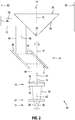
- FIG. 2 shows a second embodiment of a laser system 40 according to the invention for generating a linear laser marking on a projection surface.
- the laser system 40 of the FIG. 2 which is referred to below as the second laser system 40, differs from the first laser system 10 of FIG. 1 by a second beam-shaping optics 41 with a second optical axis 42, the second beam-shaping optics 41 being designed as focusing optics.
- the second laser system 40 comprises the laser beam source 11, the first beam shaping optics 12 with the first optical axis 13, the cone mirror 14 with the cone axis 15, the offset device 16 and the second beam shaping optics 41 with the second optical axis 42.
- the components of the second laser system 40 are arranged in the order laser beam source 11, second beam shaping optics 41 (focusing optics), first beam shaping optics 12 (collimation optics), offset device 16 and conical mirror 14.
- the first optical axis 13 of the first beam-shaping optics 12, the second optical axis 42 of the second beam-shaping optics 41 and the cone axis 15 of the cone mirror 14 are arranged coaxially to one another.
- the laser beam source 11 generates the divergent laser beam 28, which is emitted along the direction of propagation 29 and is directed onto the focusing optics 41.
- the divergent laser beam 28 hits the focusing optics 41, which generate a focused laser beam 43 .
- the focused laser beam 43 strikes the collimation optics 12, which convert the focused laser beam 43 into a collimated laser beam 44 .
- the collimated laser beam 44 strikes the offset device 16, which comprises the first and second interfaces 21, 22.
- the collimated laser beam 44 strikes the first boundary surface 21, at which a first deflection of the collimated laser beam 44 takes place, and on the second boundary surface 22, where a second deflection of the collimated laser beam 44 takes place.
- the laser beam deflected at the first boundary surface 21 is referred to as a single deflected laser beam 45 and the laser beam deflected at the second boundary surface 22 is referred to as a double deflected laser beam 46 .
- the first and second interfaces 21, 22 are aligned with one another in such a way that a direction of propagation 47 of the collimated laser beam 44 entering the displacement device 16 is arranged parallel to a direction of propagation 48 of the doubly deflected laser beam 46 emerging from the displacement device 16.
- the twice deflected laser beam 46 strikes the lateral surface 26 of the conical mirror 14 and is deflected on the lateral surface 26.
- the conical mirror 14 generates a laser beam 51, which propagates in a propagation plane 52 and generates a linear laser marking 54 on a projection surface 53.
- FIG. 3 shows a third embodiment of a laser system 60 according to the invention for generating a linear laser marking on a projection surface.
- the laser system 60 which is referred to below as the third laser system 60, comprises a laser beam source 61, a first beam-shaping optics 62 with a first optical axis 63, a cone mirror 64 with a cone axis 65, and an offset device 66 which is rotatable about an axis of rotation 67 .
- the components of the third laser system 60 are arranged in the order laser beam source 61, first beam shaping optics 62 (collimation optics), offset device 66 and conical mirror 64.
- the first optical axis 63 of the first optical beam shaping system 62, the axis of rotation 67 of the offset device 66 and the cone axis 65 of the cone mirror 64 are arranged coaxially to one another.
- the laser beam source 61 can be designed as a semiconductor laser with a wavelength in the visible spectrum.
- the properties of the further components of the third laser system 60 are adapted to the wavelength of the laser beam source 61.
- the first beam-shaping optics 62 are designed as collimation optics and are arranged behind the laser beam source 61.
- the collimation optics 62 have a light-refracting entry surface 68 and a light-refracting exit surface 69 .
- the entry surface 68 is configured as a planar first surface and the exit surface 69 is configured as a curved second surface.
- the entry surface 68 can be configured as a curved surface and the exit surface 69 as a flat surface, or the entry and exit surfaces 68, 69 are configured as curved surfaces.
- a straight line is defined as the first optical axis 63 of the collimation optics 62 which runs through the center of curvature of the curved surface and is perpendicular to the plane surface or, in the case of two curved surfaces, runs through the centers of curvature of the curved surfaces.
- the offset device 66 is arranged behind the collimation optics 62.
- the offset device 66 is designed as a transmissive offset device with a first interface 71 and a second interface 72 .
- An impinging laser beam is deflected at the first and second interfaces 71, 72.
- the degree of refraction of the first and second interfaces 71, 72 depends, among other things, on the angle of incidence and the polarization of the laser beam and on the refractive index of the offset device 66.
- the task of the offset device 66 is to determine the direction of propagation of one of the laser beam source 61 to shift the emitted laser beam relative to the cone axis 65 so that the laser beam does not hit the cone tip.
- the first and second interfaces 71, 72 are integrated in a glass plate 73 , which can be adjusted about a tilting axis 74.
- the conical mirror 64 is arranged behind the offset device 66.
- the conical mirror 64 is integrated as a conical cutout in a transparent cylindrical base body 75 .
- a cylinder is delimited by two parallel, flat surfaces, referred to as the base surface and the top surface, and a lateral surface; in the case of a straight cylinder, the base and top surface are arranged perpendicular to a cylinder axis.
- glass and plastics are suitable as materials for the base body 75.
- the conical cutout comprises a conical lateral surface 76 and a cone tip 77.
- the degree of reflection of the lateral surface 76 depends, among other things, on the angle of incidence and the polarization of the laser beam as well as the refractive index of the base body 68. So that the incident laser beam is reflected as completely as possible on the lateral surface 76, the angle of incidence should meet the condition of total reflection.
- the reflected portion can alternatively or additionally be increased by providing the jacket surface 76 with a highly reflective coating. The higher the reflected portion of the laser beam, the greater the intensity and the better the visibility of the linear laser marking on the projection surface.
- the laser beam source 61 generates a divergent laser beam 78, which is emitted along a direction of propagation 79 and is directed onto the collimation optics 62.
- the laser beam 78 strikes the collimation optics 62, which convert the divergent laser beam 78 into a collimated laser beam 81 which is directed onto the offset device 66.
- the collimated laser beam 81 strikes the first interface 71, at which a first deflection takes place, and the second interface 72, at which a second deflection of the collimated laser beam 81 takes place.
- the laser beam deflected at the first boundary surface 71 is referred to as a single deflected laser beam 82 and the laser beam deflected at the second boundary surface 72 is referred to as a double deflected laser beam 83 .
- the direction of propagation of the laser beam is shifted with respect to the cone axis 65 and the laser beam does not strike the cone tip 77.
- the twice deflected laser beam 83 spreads in a parallel direction of propagation 84 from, passes through the base of the base body 68 and is deflected on the lateral surface 76 of the conical mirror 64.
- the conical mirror 64 generates a laser beam 85, which propagates in a propagation plane 86 , passes through the outer surface of the base body 68 and generates a linear laser marking 88 on a projection surface 87.
- FIG. 4th shows a fourth embodiment of a laser system 90 according to the invention for generating a linear laser marking on a projection surface.
- the laser system 90 of the FIG. 4th which is referred to as fourth laser system 90 in the following, differs from third laser system 60 in FIG FIG. 3 by a second beam-shaping optics 91 with a second optical axis 92, the second beam-shaping optics 91 being designed as focusing optics.
- the fourth laser system 90 comprises the laser beam source 61, the first beam shaping optics 62 with the first optical axis 63, the cone mirror 64 with the cone axis 65, the offset device 66 and the second beam shaping optics 91 with the second optical axis 92.
- the components of the fourth laser system 90 are arranged in the order laser beam source 61, second beam shaping optics 91 (focusing optics), first beam shaping optics 62 (collimation optics), offset device 66 and conical mirror 64.
- the first optical axis 63 of the first beam-shaping optics 62, the second optical axis 92 of the second beam-shaping optics 91 and the cone axis 65 of the cone mirror 64 are arranged coaxially to one another.
- the laser beam source 61 generates the divergent laser beam 68, which is emitted along the direction of propagation 69.
- the divergent laser beam 68 strikes the focusing optics 91, which reduce the divergence of the laser beam 68 and generate a focused laser beam 93 .
- the focused laser beam 93 strikes the collimation optics 62, which convert the focused laser beam 93 into a collimated laser beam 95 .
- the collimated laser beam 95 strikes the offset device 66, which comprises the first and second interfaces 71, 72.
- the collimated laser beam 95 strikes the first interface 71, at which a first deflection takes place, and the second interface 72, at which a second deflection takes place.
- the laser beam deflected at the first boundary surface 71 is referred to as a single deflected laser beam 96 and the laser beam deflected at the second boundary surface 72 is referred to as a double deflected laser beam 97 .
- the direction of propagation of the laser beam is shifted with respect to the cone axis 65.
- the doubly deflected laser beam 97 propagates in a parallel direction of propagation 98 and is deflected on the lateral surface 76 of the conical mirror 14.
- the conical mirror 64 generates a laser beam 101, which propagates in a propagation plane 102 and generates a linear laser marking 104 on a projection surface 103.
- the focusing optics 91 can be designed as adjustable focusing optics, the focusing properties of which are changed and which enable the divergence of the focused laser beam to be changed.
- the focus position should be on the projection surface 103.
- the distance between the laser system 90 and the projection surface 103 is determined and the focus position is adapted to the distance.
- FIG. 5 shows a fifth embodiment of a laser system 110 according to the invention for generating a linear laser marking on a projection surface.
- the laser system 110 of FIG. 5 which is referred to below as the fifth laser system 110, differs from the second laser system 40 in FIG FIG. 2 by a second beam-shaping optics 111, which is designed as focusing optics 111 and has a second optical axis 112 , and a distance measuring device 113.
- the fifth laser system 110 comprises the laser beam source 11, the first beam shaping optics 12 with the first optical axis 13, the cone mirror 14 with the cone axis 15, the offset device 16 with the axis of rotation 17 and the second beam shaping optics 111 with the second optical axis 112
- Fifth laser system 110 are arranged in the order laser beam source 11, second beam shaping optics 111 (focusing optics), first beam shaping optics 12 (collimation optics), offset device 16 and cone mirror 14.
- the focusing optics 111 are designed as adjustable focusing optics, the focal length of which can be changed and which enables the divergence of the focused laser beam to be changed.
- the adjustable focal length of the focusing optics 111 has the advantage that the width of the linear laser marking on the projection surface can be changed by means of the focusing optics. The narrower the linear laser marking on the projection surface, the more precisely the operator can carry out the leveling or marking work. In addition, a sharply delimited line-shaped laser marking is more visible to the operator, since the available power of a maximum of 1 mW is distributed over a smaller area and a higher power density results.
- the focal length of the focusing optics 111 is adapted to the distance between the laser system 110 and the projection surface.
- the distance between the fifth laser system 110 and the projection surface is determined by means of the distance measuring device 113.
Landscapes
- Physics & Mathematics (AREA)
- General Physics & Mathematics (AREA)
- Optics & Photonics (AREA)
- Engineering & Computer Science (AREA)
- Radar, Positioning & Navigation (AREA)
- Remote Sensing (AREA)
- Laser Beam Processing (AREA)
- Lasers (AREA)
Abstract
Lasersystem (10) zur Erzeugung einer linienförmigen Lasermarkierung (38) auf einer Projektionsfläche (37), aufweisend eine Laserstrahlquelle (11), die einen Laserstrahl (28) erzeugt und entlang einer Ausbreitungsrichtung (29) aussendet, eine Versatzeinrichtung (16) mit einer ersten Grenzfläche (21), an der eine erste Umlenkung des Laserstrahls erfolgt, und einen Kegelspiegel (14), der als gerader Kegel mit einer Kegelachse (15) und einer reflektierenden Mantelfläche (26) ausgebildet ist, wobei der Kegelspiegel (14) im Strahlengang des Laserstrahls hinter der Versatzeinrichtung (16) angeordnet ist. Die Versatzeinrichtung (16) ist um eine Rotationsachse (17) drehbar ausgebildet, die koaxial zur Kegelachse (15) angeordnet ist.Laser system (10) for generating a linear laser marking (38) on a projection surface (37), comprising a laser beam source (11) which generates a laser beam (28) and emits it along a direction of propagation (29), an offset device (16) with a first Interface (21) at which a first deflection of the laser beam takes place, and a conical mirror (14) which is designed as a straight cone with a cone axis (15) and a reflective lateral surface (26), the conical mirror (14) in the beam path of the Laser beam is arranged behind the offset device (16). The offset device (16) is designed to be rotatable about an axis of rotation (17) which is arranged coaxially to the cone axis (15).
Description
Die vorliegende Erfindung betrifft ein Lasersystem zur Erzeugung einer linienförmigen Lasermarkierung auf einer Projektionsfläche gemäß dem Oberbegriff des Anspruchs 1.The present invention relates to a laser system for generating a linear laser marking on a projection surface according to the preamble of claim 1.
Um Nivellier- oder Markierungsarbeiten im Innen- und Außenbereich durchzuführen, sind Lasersysteme bekannt, die auf einer Projektionsfläche eine linienförmige Lasermarkierung erzeugen. Bei diesen Lasersystemen wird unterschieden zwischen Rotationslasern, die die linienförmige Lasermarkierung durch Rotation einer Strahlumlenkoptik um eine Rotationsachse erzeugen, und Linienlasern, die die linienförmige Lasermarkierung mithilfe einer Strahlformungsoptik, beispielsweise einer Zylinderlinse, einem Prisma oder einem Kegelspiegel, erzeugt. Damit die bekannten Lasersysteme ohne Schutzmaßnahmen in Form von Schutzbrillen und Reflektoren eingesetzt werden können, muss die Laserleistung begrenzt werden, um Schäden des menschlichen Auges zu verhindern. Für Lasersysteme der Laserklasse 2 oder 2M beträgt die maximal zulässige Laserleistung 1 mW.In order to carry out leveling or marking work indoors and outdoors, laser systems are known which produce a linear laser marking on a projection surface. With these laser systems, a distinction is made between rotary lasers, which generate the line-shaped laser marking by rotating a beam deflecting lens around an axis of rotation, and line lasers, which generate the line-shaped laser marking using beam-shaping optics, for example a cylinder lens, a prism or a conical mirror. So that the known laser systems can be used without protective measures in the form of protective goggles and reflectors, the laser power must be limited in order to prevent damage to the human eye. For laser systems of laser class 2 or 2M, the maximum permissible laser power is 1 mW.
Durch die Begrenzung der Laserleistung auf Werte kleiner als 1 mW weisen bekannte Lasersysteme der Laserklasse 2 oder 2M den Nachteil auf, dass die linienförmige Lasermarkierung auf der Projektionsfläche schlecht sichtbar ist. Dabei gilt, dass die linienförmige Lasermarkierung umso schlechter sichtbar ist, je breiter die Lasermarkierung auf der Projektionsfläche ist, da die Sichtbarkeit mit sinkender Leistungsdichte abnimmt. Außerdem ist die Qualität der linienförmigen Lasermarkierung auf der Projektionsfläche vom Abstand des Lasersystem zur Projektionsfläche abhängig.By limiting the laser power to values less than 1 mW, known laser systems of laser class 2 or 2M have the disadvantage that the linear laser marking is difficult to see on the projection surface. The rule here is that the line-shaped laser marking is less visible, the wider the laser marking is on the projection surface, since visibility decreases with decreasing power density. In addition, the quality of the linear laser marking on the projection surface depends on the distance between the laser system and the projection surface.
Das aus
Das aus
Die Aufgabe der vorliegenden Erfindung besteht in der Entwicklung eines Lasersystems, mit dem auf einer Projektionsfläche eine scharf begrenzte, gut sichtbare linienförmige Lasermarkierung mit einem Öffnungswinkel von 360° erzeugt werden kann. Außerdem soll das Lasersystem möglichst kompakt ausgebildet sein.The object of the present invention is to develop a laser system with which a sharply delimited, easily visible linear laser marking with an opening angle of 360 ° can be produced on a projection surface. In addition, the laser system should be designed to be as compact as possible.
Diese Aufgabe wird bei dem eingangs genannten Lasersystem erfindungsgemäß durch die Merkmale des unabhängigen Anspruchs 1 gelöst. Vorteilhafte Weiterbildungen sind in den abhängigen Ansprüchen angegeben.In the case of the laser system mentioned at the outset, this object is achieved according to the invention by the features of independent claim 1. Advantageous further developments are given in the dependent claims.
Erfindungsgemäß ist das Lasersystem dadurch gekennzeichnet, dass die Versatzeinrichtung um eine Rotationsachse drehbar ausgebildet ist, wobei die Rotationsachse der Versatzeinrichtung koaxial zur Kegelachse angeordnet ist. Das erfindungsgemäße Lasersystem erzeugt eine linienförmige Lasermarkierung, die einen Öffnungswinkel von 360° aufweist und die auf der Projektionsfläche scharf begrenzt und gut sichtbar ist. Durch die Versatzeinrichtung wird die optische Achse des Laserstrahls gegenüber der Kegelachse verschoben und der Laserstrahl trifft nicht auf die Kegelspitze des Kegelspiegels, so dass Beugungseffekte an der Kegelspitze, die zu einer unscharfen Lasermarkierung führen können, reduziert sind.According to the invention, the laser system is characterized in that the offset device is designed to be rotatable about an axis of rotation, the axis of rotation of the offset device being arranged coaxially to the cone axis. The laser system according to the invention generates a linear laser marking which has an opening angle of 360 ° and which is sharply delimited and clearly visible on the projection surface. The offset device shifts the optical axis of the laser beam relative to the cone axis and the laser beam does not hit the cone tip of the cone mirror, so that diffraction effects at the cone tip, which can lead to a blurred laser marking, are reduced.
Der Kegelspiegel erzeugt einen linienförmigen Laserstrahl mit einem Öffnungswinkel, der kleiner als 180° ist. Durch die Rotation der Versatzeinrichtung wird auf der Projektionsfläche eine linienförmige Lasermarkierung mit einem Öffnungswinkel von 360° erzeugt. Das erfindungsgemäße Lasersystem hat gegenüber einem herkömmlichen Rotationslaser den Vorteil, dass geringere Rotationsgeschwindigkeiten möglich sind, die zu einer besseren Sichtbarkeit der Lasermarkierung auf der Projektionsfläche führen. Bei herkömmlichen Rotationslasern muss der punktförmige Laserstrahl mit einer hohen Rotationsgeschwindigkeit bewegt werden, um für das Auge des Benutzers auf der Projektionsfläche eine geschlossene linienförmige Lasermarkierung zu erzeugen.The conical mirror generates a linear laser beam with an opening angle that is less than 180 °. By rotating the offset device, a linear laser marking with an opening angle of 360 ° is generated on the projection surface. The laser system according to the invention has the advantage over a conventional rotating laser that lower rotation speeds are possible, which lead to better visibility of the laser marking on the projection surface. With conventional rotating lasers, the point-shaped laser beam must be moved at a high rotational speed in order to generate a closed, linear laser marking on the projection surface for the user's eye.
Bevorzugt umfasst die Versatzeinrichtung eine zweite Grenzfläche, an der eine zweite Umlenkung des Laserstrahls erfolgt, wobei die Ausbreitungsrichtung eines in die Versatzeinrichtung eintretenden Laserstrahls parallel zur Ausbreitungsrichtung eines aus der Versatzeinrichtung austretenden Laserstrahls angeordnet ist. Eine Versatzeinrichtung, die eine erste und zweite Grenzfläche aufweist, ermöglicht einen kompakten Aufbau des Lasersystems. Bei einer Versatzeinrichtung, die nur eine erste Grenzfläche aufweist, müssen die Laserstrahlquelle und die Versatzeinrichtung sowie weitere optische Elemente, die zwischen Laserstrahlquelle und Versatzeinrichtung angeordnet sind, drehbar ausgebildet sein; bei einer Versatzeinrichtung mit einer ersten und zweiten Grenzfläche ist es ausreichend, dass die Versatzeinrichtung drehbar ausgebildet ist.The offset device preferably comprises a second interface at which a second deflection of the laser beam takes place, the direction of propagation of a laser beam entering the offset device being arranged parallel to the direction of propagation of a laser beam exiting the offset device. An offset device which has a first and a second interface enables a compact construction of the laser system. In the case of an offset device which has only a first interface, the laser beam source and the offset device as well as further optical elements which are arranged between the laser beam source and the offset device must be designed to be rotatable; In the case of an offset device with a first and second boundary surface, it is sufficient that the offset device is designed to be rotatable.
Bevorzugt weist das Lasersystem eine als Kollimationsoptik ausgebildete erste Strahlformungsoptik mit einer ersten optischen Achse auf, wobei die erste optische Achse parallel zur Kegelachse ausgerichtet ist. Die Erweiterung des erfindungsgemäßen Lasersystems um die Kollimationsoptik hat den Vorteil, dass ein divergenter Laserstrahl kollimiert werden kann. Auf der Projektionsfläche ist der kollimierte Laserstrahl gegenüber einem divergenten Laserstrahl besser sichtbar, da die Leistungsdichte grösser ist. Eine linienförmige Lasermarkierung ist umso besser sichtbar, je schmaler die Lasermarkierung auf der Projektionsfläche ist, da die Sichtbarkeit mit steigender Leistungsdichte zunimmt.The laser system preferably has first beam-shaping optics, designed as collimation optics, with a first optical axis, the first optical axis being aligned parallel to the cone axis. The expansion of the laser system according to the invention by the collimation optics has the advantage that a divergent laser beam can be collimated. The collimated laser beam is opposite a divergent laser beam on the projection surface more visible because the power density is greater. A linear laser marking is all the more visible, the narrower the laser marking is on the projection surface, since visibility increases with increasing power density.
Bevorzugt weist das Lasersystem eine als Fokussieroptik mit einer Brennweite ausgebildete zweite Strahlformungsoptik mit einer zweiten optischen Achse auf, wobei die zweite Strahlformungsoptik im Strahlengang des Laserstrahls zwischen der Laserstrahlquelle und der ersten Strahlformungsoptik angeordnet ist und die zweite optische Achse parallel zur Kegelachse ausgerichtet ist. Die Erweiterung des erfindungsgemäßen Lasersystems um eine Fokussieroptik hat den Vorteil, dass der Strahldurchmesser des Laserstrahls angepasst werden kann. Als Fokussieroptik ist ein optisches Element definiert, das eine endliche Brennweite aufweist und einen auftreffenden Laserstrahl fokussiert, wobei der Strahldurchmesser des Laserstrahls in der Fokuslage minimal ist. Ein fokussierter Laserstrahl weist im Bereich der Fokuslage einen kleineren Strahldurchmesser auf als ein nicht-fokussierter Laserstrahl. Der kleinere Strahldurchmesser hat den Vorteil, dass die erste Strahlformungsoptik, die Versatzeinrichtung und der Kegelspiegel kleinere Abmessungen aufweisen können.The laser system preferably has a second beam-shaping optic designed as focusing optics with a focal length and a second optical axis, the second beam-shaping optics being arranged in the beam path of the laser beam between the laser beam source and the first beam-shaping optics and the second optical axis being aligned parallel to the cone axis. The expansion of the laser system according to the invention to include focusing optics has the advantage that the beam diameter of the laser beam can be adapted. An optical element is defined as focusing optics, which has a finite focal length and focuses an impinging laser beam, the beam diameter of the laser beam being minimal in the focus position. A focused laser beam has a smaller beam diameter in the area of the focal position than a non-focused laser beam. The smaller beam diameter has the advantage that the first beam-shaping optics, the offset device and the conical mirror can have smaller dimensions.
Besonders bevorzugt ist die Brennweite der Fokussieroptik verstellbar. Eine Fokussieroptik mit verstellbarer Brennweite hat den Vorteil, dass die Breite der linienförmigen Lasermarkierung auf der Projektionsfläche mittels der Fokussieroptik verändert werden kann. Je schmaler die linienförmige Lasermarkierung auf der Projektionsfläche ist, umso genauer kann der Bediener die Nivellier- oder Markierungsarbeiten ausführen. Außerdem ist eine scharf begrenzte linienförmige Lasermarkierung für den Bediener besser sichtbar, da die verfügbare Leistung von maximal 1 mW auf eine kleinere Fläche verteilt wird und eine höhere Leistungsdichte resultiert.The focal length of the focusing optics is particularly preferably adjustable. Focusing optics with adjustable focal length have the advantage that the width of the linear laser marking on the projection surface can be changed by means of the focusing optics. The narrower the linear laser marking on the projection surface, the more precisely the operator can carry out the leveling or marking work. In addition, a sharply delimited line-shaped laser marking is more visible to the operator, since the available power of a maximum of 1 mW is distributed over a smaller area, resulting in a higher power density.
In einer bevorzugten Ausführung ist die Versatzeinrichtung als reflektierende Versatzeinrichtung ausgebildet und die Umlenkung des Laserstrahls an der ersten Grenzfläche und zweiten Grenzfläche erfolgt durch Reflexion. Ein erfindungsgemäßes Lasersystem mit einer reflektierenden Versatzeinrichtung hat den Vorteil, dass die erste Grenzfläche und zweite Grenzfläche in separate optische Elemente integriert werden können, die unabhängig voneinander verstellbar sein können.In a preferred embodiment, the offset device is designed as a reflective offset device and the deflection of the laser beam at the first interface and the second interface takes place by reflection. A laser system according to the invention with a reflective offset device has the advantage that the first interface and the second interface can be integrated into separate optical elements which can be adjusted independently of one another.
Besonders bevorzugt ist die erste Grenzfläche um eine erste Kippachse und/oder die zweite Grenzfläche um eine zweite Kippachse verstellbar ausgebildet, wobei die erste Kippachse und zweite Kippachse senkrecht zur Rotationsachse ausgerichtet sind. Eine reflektierende erste Grenzfläche, die um eine erste Kippachse verstellbar ist, und/oder eine reflektierende zweite Grenzfläche, die um eine zweite Kippachse verstellbar ist, bietet die Möglichkeit, den Einfallswinkel des Laserstrahls auf die Mantelfläche zu verändern. Ziel ist es, mit dem Kegelspiegel einen linienförmigen Laserstrahl mit einer Ausbreitungsebene zu erzeugen, die senkrecht zur Kegelachse verläuft.The first interface is particularly preferably designed to be adjustable around a first tilt axis and / or the second interface around a second tilt axis, the first tilt axis and second tilt axis being oriented perpendicular to the axis of rotation. A reflective first interface that is adjustable about a first tilt axis and / or a reflective second interface that is adjustable about a second tilt axis offers the possibility of changing the angle of incidence of the laser beam on the lateral surface. The goal is with the cone mirror to generate a linear laser beam with a plane of propagation that is perpendicular to the cone axis.
In einer Weiterentwicklung weist das Lasersystem eine Distanzmesseinrichtung auf, wobei die Distanzmesseinrichtung geeignet ist, einen Abstand des Lasersystems zur Projektionsfläche zu bestimmen. Die Erweiterung des erfindungsgemäßen Lasersystems um eine Distanzmesseinrichtung hat den Vorteil, dass die Brennweite der Fokussieroptik an den Abstand des Lasersystems zur Projektionsfläche angepasst werden kann.In a further development, the laser system has a distance measuring device, the distance measuring device being suitable for determining a distance between the laser system and the projection surface. The expansion of the laser system according to the invention by a distance measuring device has the advantage that the focal length of the focusing optics can be adapted to the distance between the laser system and the projection surface.
Ausführungsbeispiele der Erfindung werden nachfolgend anhand der Zeichnung beschrieben. Diese soll die Ausführungsbeispiele nicht notwendigerweise maßstäblich darstellen, vielmehr ist die Zeichnung, wo zur Erläuterung dienlich, in schematischer und/oder leicht verzerrter Form ausgeführt. Dabei ist zu berücksichtigen, dass vielfältige Modifikationen und Änderungen betreffend die Form und das Detail einer Ausführungsform vorgenommen werden können, ohne von der allgemeinen Idee der Erfindung abzuweichen. Die allgemeine Idee der Erfindung ist nicht beschränkt auf die exakte Form oder das Detail der im Folgenden gezeigten und beschriebenen bevorzugten Ausführungsform oder beschränkt auf einen Gegenstand, der eingeschränkt wäre im Vergleich zu dem in den Ansprüchen beanspruchten Gegenstand. Bei gegebenen Bemessungsbereichen sollen auch innerhalb der genannten Grenzen liegende Werte als Grenzwerte offenbart und beliebig einsetzbar und beanspruchbar sein. Der Einfachheit halber sind nachfolgend für identische oder ähnliche Teile oder Teile mit identischer oder ähnlicher Funktion gleiche Bezugszeichen verwendet.Embodiments of the invention are described below with reference to the drawing. This is not necessarily intended to represent the exemplary embodiments to scale; rather, the drawing, where useful for explanation, is in a schematic and / or slightly distorted form. It must be taken into account here that various modifications and changes relating to the form and the detail of an embodiment can be made without deviating from the general idea of the invention. The general idea of the invention is not limited to the exact form or the detail of the preferred embodiment shown and described below or limited to an object which would be restricted in comparison to the object claimed in the claims. Given the measurement ranges, values lying within the stated limits should also be disclosed as limit values and be able to be used and claimed as required. For the sake of simplicity, the same reference symbols are used below for identical or similar parts or parts with an identical or similar function.
Es zeigen:
- FIG. 1
- eine erste Ausführungsform eines erfindungsgemäßen Lasersystems, das eine Laserstrahlquelle, eine Kollimationsoptik, eine Versatzeinrichtung, die als reflektierende Versatzeinrichtung ausgebildet ist, und einen Kegelspiegel aufweist;
- FIG. 2
- eine zweite Ausführungsform eines erfindungsgemäßen Lasersystems, das sich durch eine Fokussieroptik von der ersten Ausführungsform des Lasersystems unterscheidet;
- FIG. 3
- eine dritte Ausführungsform eines erfindungsgemäßen Lasersystems, das eine Laserstrahlquelle, eine Kollimationsoptik, eine Versatzeinrichtung, die als transmittierende Versatzeinrichtung ausgebildet ist, und einen Kegelspiegel aufweist;
- FIG. 4
- eine vierte Ausführungsform eines erfindungsgemäßen Lasersystems, das sich durch eine Fokussieroptik von der dritten Ausführungsform des Lasersystems unterscheidet; und
- FIG. 5
- eine fünfte Ausführungsform eines erfindungsgemäßen Lasersystems, das sich durch eine Fokussieroptik, die in ihren fokussierenden Eigenschaften verstellbar ist, von der zweiten Ausführungsform des Lasersystems unterscheidet.
- FIG. 1
- a first embodiment of a laser system according to the invention which has a laser beam source, collimation optics, an offset device which is designed as a reflective offset device, and a conical mirror;
- FIG. 2
- a second embodiment of a laser system according to the invention which differs from the first embodiment of the laser system in terms of focusing optics;
- FIG. 3
- a third embodiment of a laser system according to the invention, which has a laser beam source, collimation optics, an offset device, which is designed as a transmitting offset device, and a conical mirror;
- FIG. 4th
- a fourth embodiment of a laser system according to the invention, which differs from the third embodiment of the laser system in terms of focusing optics; and
- FIG. 5
- a fifth embodiment of a laser system according to the invention, which differs from the second embodiment of the laser system by focusing optics which can be adjusted in their focusing properties.
Die Laserstrahlquelle 11 kann als Halbleiterlaser mit einer Wellenlänge im sichtbaren Spektrum ausgebildet sein, beispielsweise als roter Halbleiterlaser mit einer Wellenlänge von 635 nm oder als grüner Halbleiterlaser mit einer Wellenlänge zwischen 510 und 555 nm. Die Eigenschaften der weiteren Komponenten des ersten Lasersystems 10 sind an die Wellenlänge der Laserstrahlquelle 11 angepasst.The
Hinter der Laserstrahlquelle 11 ist die erste Strahlformungsoptik 12 angeordnet, die als Kollimationsoptik ausgebildet ist und die einen auftreffenden Laserstrahl umformt. Die Kollimationsoptik 12 weist eine plane Eintrittsfläche 18 und eine gekrümmte Austrittsfläche 19 auf. Alternativ kann die Eintrittsfläche 18 als gekrümmte Fläche und die Austrittsfläche 19 als plane Fläche ausgebildet sein oder die Ein- und Austrittsflächen 18, 19 sind als gekrümmte Flächen ausgebildet. Als erste optische Achse 13 der Kollimationsoptik 12 ist eine Gerade definiert, die durch den Krümmungsmittelpunkt der gekrümmten Fläche verläuft und senkrecht auf der planen Fläche steht oder bei zwei gekrümmten Flächen durch die Krümmungsmittelpunkte der gekrümmten Flächen verläuft.The first beam-shaping
Hinter der Kollimationsoptik 12 ist die Versatzeinrichtung 16 angeordnet. Die Versatzeinrichtung 16 ist als reflektierende Versatzeinrichtung mit einem ersten Spiegel und einem zweiten Spiegel ausgebildet. Der erste Spiegel weist eine erste Grenzfläche 21 und der zweite Spiegel eine zweite Grenzfläche 22 auf. Ein auftreffender Laserstrahl wird an der ersten und zweiten Grenzfläche 21, 22 reflektiert. Dabei hängt der Reflexionsgrad der ersten und zweiten Grenzfläche 21, 22 unter anderem vom Einfallswinkel und der Polarisation des Laserstrahls sowie vom Brechungsindex des ersten und zweiten Spiegels ab. Die Aufgabe der Versatzeinrichtung 16 besteht darin, die Ausbreitungsrichtung eines von der Laserstrahlquelle 11 ausgesandten Laserstrahls so gegenüber der Kegelachse 15 zu verschieben, dass der Laserstrahl nicht auf die Kegelspitze trifft. Um den Einfallswinkel des Laserstrahls zu verändern, kann die Ausbreitungsrichtung des Laserstrahls und/oder die Neigung der ersten und zweiten Grenzfläche 21, 22 verstellt werden. Die erste Grenzfläche 21 kann um eine erste Kippachse 23 und die zweite Grenzfläche 21 um eine zweite Kippachse 24 verstellt werden.The offset
Hinter der Versatzeinrichtung 16 ist der Kegelspiegel 14 angeordnet. Der Kegelspiegel 14 ist als Abschnitt eines geraden Kegels ausgebildet. Ein Kegel ist von einer Grundfläche und einer Mantelfläche begrenzt, wobei die Grundfläche bei einem geraden Kegel senkrecht zur Kegelachse angeordnet ist. Die Oberfläche des Kegelspiegels 14 umfasst eine kreisförmige Grundfläche 25, eine Mantelfläche 26 und eine Kegelspitze 27, wobei die Kegelachse 15 senkrecht zur Grundfläche 25 angeordnet ist und durch die Kegelspitze 27 verläuft. Die Mantelfläche 26 ist für die Wellenlänge der Laserstrahlquelle 11 als reflektierende Mantelfläche ausgebildet und ein auf die Mantelfläche 26 auftreffender Laserstrahl wird an der Mantelfläche 26 überwiegend reflektiert. Der Reflexionsgrad der Mantelfläche 26 hängt unter anderem vom Einfallswinkel eines auftreffenden Laserstrahls, von der Polarisation des auftreffenden Laserstrahls und vom Brechungsindex des Kegelspiegels 15 ab.The
Die Laserstrahlquelle 11 erzeugt einen divergenten Laserstrahl 28, der entlang einer Ausbreitungsrichtung 29 ausgesandt wird und auf die erste Strahlformungsoptik 16 gerichtet ist. Ohne ein zusätzliches optisches Element in der Laserstrahlquelle 11 ist der Laserstrahl 28 divergent. Als optische Achse des Laserstrahls 28 ist die Symmetrieachse der Strahlverteilung definiert.The
Der Laserstrahl 28 trifft auf die Kollimationsoptik 12, die den divergenten Laserstrahl 28 in einen kollimierten Laserstrahl 31 umformt, der auf die Versatzeinrichtung 16 gerichtet ist. Der kollimierte Laserstrahl 31 trifft auf die erste Grenzfläche 21, an der eine erste Umlenkung des kollimierten Laserstrahls 31 erfolgt, und auf die zweite Grenzfläche 22, an der eine zweite Umlenkung des kollimierten Laserstrahls 31 erfolgt. Der an der ersten Grenzfläche 21 umgelenkte Laserstrahl wird als einfach umgelenkter Laserstrahl 32 und der an der zweiten Grenzfläche 22 umgelenkte Laserstrahl als zweifach umgelenkter Laserstrahl 33 bezeichnet. Durch die zweifache Umlenkung des Laserstrahls an der ersten und zweiten Grenzfläche 21, 22 der Versatzeinrichtung 16 ist die Ausbreitungsrichtung des Laserstrahls gegenüber der Kegelachse 15 verschoben und der Laserstrahl trifft nicht auf die Kegelspitze 27. Der zweifach umgelenkte Laserstrahl 33 breitet sich in einer parallelen Ausbreitungsrichtung 34 aus und wird an der Mantelfläche 26 des Kegelspiegels 14 umgelenkt. Der Kegelspiegel 14 erzeugt einen Laserstrahl 35, der sich in einer Ausbreitungsebene 36 ausbreitet und auf einer Projektionsfläche 37 eine linienförmige Lasermarkierung 38 erzeugt.The
Das zweite Lasersystem 40 umfasst die Laserstrahlquelle 11, die erste Strahlformungsoptik 12 mit der ersten optischen Achse 13, den Kegelspiegel 14 mit der Kegelachse 15, die Versatzeinrichtung 16 und die zweite Strahlformungsoptik 41 mit der zweiten optischen Achse 42. Die Komponenten des zweiten Lasersystems 40 sind in der Reihenfolge Laserstrahlquelle 11, zweite Strahlformungsoptik 41 (Fokussieroptik), erste Strahlformungsoptik 12 (Kollimationsoptik), Versatzeinrichtung 16 und Kegelspiegel 14 angeordnet. Dabei sind die erste optische Achse 13 der ersten Strahlformungsoptik 12, die zweite optische Achse 42 der zweiten Strahlformungsoptik 41 und die Kegelachse 15 des Kegelspiegels 14 koaxial zueinander angeordnet.The
Die Laserstrahlquelle 11 erzeugt den divergenten Laserstrahl 28, der entlang der Ausbreitungsrichtung 29 ausgesandt wird und auf die Fokussieroptik 41 gerichtet ist. Der divergente Laserstrahl 28 trifft auf die Fokussieroptik 41, die einen fokussierten Laserstrahl 43 erzeugt. Der fokussierte Laserstrahl 43 trifft auf die Kollimationsoptik 12, die den fokussierten Laserstrahl 43 in einen kollimierten Laserstrahl 44 umformt.The
Der kollimierte Laserstrahl 44 trifft auf die Versatzeinrichtung 16, die die erste und zweite Grenzfläche 21, 22 umfasst. Der kollimierte Laserstrahl 44 trifft auf die erste Grenzfläche 21, an der eine erste Umlenkung des kollimierten Laserstrahls 44 erfolgt, und auf die zweite Grenzfläche 22, an der eine zweite Umlenkung des kollimierten Laserstrahls 44 erfolgt. Der an der ersten Grenzfläche 21 umgelenkte Laserstrahl wird als einfach umgelenkter Laserstrahl 45 und der an der zweiten Grenzfläche 22 umgelenkte Laserstrahl als zweifach umgelenkter Laserstrahl 46 bezeichnet. Die erste und zweite Grenzfläche 21, 22 sind so zueinander ausgerichtet, dass eine Ausbreitungsrichtung 47 des in die Versatzeinrichtung 16 eintretenden kollimierten Laserstrahls 44 parallel zu einer Ausbreitungsrichtung 48 des aus der Versatzeinrichtung 16 austretenden zweifach umgelenkten Laserstrahls 46 angeordnet ist.The collimated
Der zweifach umgelenkte Laserstrahl 46 trifft auf die Mantelfläche 26 des Kegelspiegels 14 und wird an der Mantelfläche 26 umgelenkt. Der Kegelspiegel 14 erzeugt einen Laserstrahl 51, der sich in einer Ausbreitungsebene 52 ausbreitet und auf einer Projektionsfläche 53 eine linienförmige Lasermarkierung 54 erzeugt.The twice deflected
Die Laserstrahlquelle 61 kann wie die Laserstrahlquelle 11 des ersten Lasersystems 10 als Halbleiterlaser mit einer Wellenlänge im sichtbaren Spektrum ausgebildet sein. Die Eigenschaften der weiteren Komponenten des dritten Lasersystems 60 sind an die Wellenlänge der Laserstrahlquelle 61 angepasst.Like the
Die erste Strahlformungsoptik 62 ist als Kollimationsoptik ausgebildet und hinter der Laserstrahlquelle 61 angeordnet. Die Kollimationsoptik 62 weist eine lichtbrechende Eintrittsfläche 68 und eine lichtbrechende Austrittsfläche 69 auf. Im Ausführungsbeispiel ist die Eintrittsfläche 68 als plane erste Fläche und die Austrittsfläche 69 als gekrümmte zweite Fläche ausgebildet. Alternativ kann die Eintrittsfläche 68 als gekrümmte Fläche und die Austrittsfläche 69 als plane Fläche ausgebildet sein oder die Ein- und Austrittsflächen 68, 69 sind als gekrümmte Flächen ausgebildet. Als erste optische Achse 63 der Kollimationsoptik 62 ist eine Gerade definiert, die durch den Krümmungsmittelpunkt der gekrümmten Fläche verläuft und senkrecht auf der planen Fläche steht oder bei zwei gekrümmten Flächen durch die Krümmungsmittelpunkte der gekrümmten Flächen verläuft.The first beam-shaping
Hinter der Kollimationsoptik 62 ist die Versatzeinrichtung 66 angeordnet. Die Versatzeinrichtung 66 ist als transmittierende Versatzeinrichtung mit einer ersten Grenzfläche 71 und einer zweiten Grenzfläche 72 ausgebildet. Ein auftreffender Laserstrahl wird an der ersten und zweiten Grenzfläche 71, 72 abgelenkt. Dabei hängt der Brechungsgrad der ersten und zweiten Grenzfläche 71, 72 unter anderem vom Einfallswinkel und der Polarisation des Laserstrahls sowie vom Brechungsindex der Versatzeinrichtung 66 ab. Die Aufgabe der Versatzeinrichtung 66 besteht darin, die Ausbreitungsrichtung eines von der Laserstrahlquelle 61 ausgesandten Laserstrahls so gegenüber der Kegelachse 65 zu verschieben, dass der Laserstrahl nicht auf die Kegelspitze trifft. Die erste und zweite Grenzfläche 71, 72 sind in eine Glasplatte 73 integriert, die um eine Kippachse 74 verstellbar ist.The offset
Hinter der Versatzeinrichtung 66 ist der Kegelspiegel 64 angeordnet. Der Kegelspiegel 64 ist als kegelförmiger Ausschnitt in einen transparenten zylinderförmigen Grundkörper 75 integriert. Ein Zylinder ist von zwei parallelen, ebenen Flächen, die als Grundfläche und Deckfläche bezeichnet werden, und einer Mantelfläche begrenzt; bei einem geraden Zylinder sind die Grund- und Deckfläche senkrecht zu einer Zylinderachse angeordnet. Als Materialien für den Grundkörper 75 eignen sich beispielsweise Glas und Kunststoffe. Der kegelförmige Ausschnitt umfasst eine kegelförmige Mantelfläche 76 und eine Kegelspitze 77. The
Der Reflexionsgrad der Mantelfläche 76 hängt unter anderem vom Einfallswinkel und der Polarisation des Laserstrahls sowie dem Brechungsindex des Grundkörpers 68 ab. Damit der einfallende Laserstrahl möglichst vollständig an der Mantelfläche 76 reflektiert wird, sollte der Einfallswinkel die Bedingung der Totalreflektion erfüllen. Der reflektierte Anteil kann alternativ oder zusätzlich dadurch erhöht werden, dass die Mantelfläche 76 mit einer hochreflektierenden Beschichtung versehen wird. Je höher der reflektierte Anteil des Laserstrahls ist, umso größer ist die Intensität und umso besser ist die Sichtbarkeit der linienförmigen Lasermarkierung auf der Projektionsfläche.The degree of reflection of the
Die Laserstrahlquelle 61 erzeugt einen divergenten Laserstrahl 78, der entlang einer Ausbreitungsrichtung 79 ausgesandt wird und auf die Kollimationsoptik 62 gerichtet ist. Der Laserstrahl 78 trifft auf die Kollimationsoptik 62, die den divergenten Laserstrahl 78 in einen kollimierten Laserstrahl 81 umformt, der auf die Versatzeinrichtung 66 gerichtet ist. Der kollimierte Laserstrahl 81 trifft auf die erste Grenzfläche 71, an der eine erste Umlenkung erfolgt, und auf die zweite Grenzfläche 72, an der eine zweite Umlenkung des kollimierten Laserstrahls 81 erfolgt. Der an der ersten Grenzfläche 71 umgelenkte Laserstrahl wird als einfach umgelenkter Laserstrahl 82 und der an der zweiten Grenzfläche 72 umgelenkte Laserstrahl als zweifach umgelenkter Laserstrahl 83 bezeichnet.The
Durch die zweifache Umlenkung des Laserstrahls an der ersten und zweiten Grenzfläche 71, 72 der Versatzeinrichtung 66 ist die Ausbreitungsrichtung des Laserstrahls gegenüber der Kegelachse 65 verschoben und der Laserstrahl trifft nicht auf die Kegelspitze 77. Der zweifach umgelenkte Laserstrahl 83 breitet sich in einer parallelen Ausbreitungsrichtung 84 aus, tritt durch die Grundfläche des Grundkörpers 68 und wird an der Mantelfläche 76 des Kegelspiegels 64 umgelenkt. Der Kegelspiegel 64 erzeugt einen Laserstrahl 85, der sich in einer Ausbreitungsebene 86 ausbreitet, durch die Mantelfläche des Grundkörpers 68 tritt und auf einer Projektionsfläche 87 eine linienförmige Lasermarkierung 88 erzeugt.As a result of the double deflection of the laser beam at the first and
Das vierte Lasersystem 90 umfasst die Laserstrahlquelle 61, die erste Strahlformungsoptik 62 mit der ersten optischen Achse 63, den Kegelspiegel 64 mit der Kegelachse 65, die Versatzeinrichtung 66 und die zweite Strahlformungsoptik 91 mit der zweiten optischen Achse 92. Die Komponenten des vierten Lasersystems 90 sind in der Reihenfolge Laserstrahlquelle 61, zweite Strahlformungsoptik 91 (Fokussieroptik), erste Strahlformungsoptik 62 (Kollimationsoptik), Versatzeinrichtung 66 und Kegelspiegel 64 angeordnet. Dabei sind die erste optische Achse 63 der ersten Strahlformungsoptik 62, die zweite optische Achse 92 der zweiten Strahlformungsoptik 91 und die Kegelachse 65 des Kegelspiegels 64 koaxial zueinander angeordnet.The
Die Laserstrahlquelle 61 erzeugt den divergenten Laserstrahl 68, der entlang der Ausbreitungsrichtung 69 ausgesandt wird. Der divergente Laserstrahl 68 trifft auf die Fokussieroptik 91, die die Divergenz des Laserstrahls 68 verringert und einen fokussierten Laserstrahl 93 erzeugt. Der fokussierte Laserstrahl 93 trifft auf die Kollimationsoptik 62, die den fokussierten Laserstrahl 93 in einen kollimierten Laserstrahl 95 umformt.The
Der kollimierte Laserstrahl 95 trifft auf die Versatzeinrichtung 66, die die erste und zweite Grenzfläche 71, 72 umfasst. Der kollimierte Laserstrahl 95 trifft auf die erste Grenzfläche 71, an der eine erste Umlenkung erfolgt, und auf die zweite Grenzfläche 72, an der eine zweite Umlenkung erfolgt. Der an der ersten Grenzfläche 71 umgelenkte Laserstrahl wird als einfach umgelenkter Laserstrahl 96 und der an der zweiten Grenzfläche 72 umgelenkte Laserstrahl als zweifach umgelenkter Laserstrahl 97 bezeichnet.The collimated
Durch die zweifache Umlenkung des Laserstrahls an der ersten und zweiten Grenzfläche 71, 72 der Versatzeinrichtung 66 ist die Ausbreitungsrichtung des Laserstrahls gegenüber der Kegelachse 65 verschoben. Der zweifach umgelenkte Laserstrahl 97 breitet sich in einer parallelen Ausbreitungsrichtung 98 aus und wird an der Mantelfläche 76 des Kegelspiegels 14 umgelenkt. Der Kegelspiegel 64 erzeugt einen Laserstrahl 101, der sich in einer Ausbreitungsebene 102 ausbreitet und auf einer Projektionsfläche 103 eine linienförmige Lasermarkierung 104 erzeugt.As a result of the double deflection of the laser beam at the first and
Die Fokussieroptik 91 kann als verstellbare Fokussieroptik ausgebildet sein, deren fokussierende Eigenschaften verändert werden und die eine Veränderung der Divergenz des fokussierten Laserstrahls ermöglicht. Um eine scharfe Lasermarkierung 104, d.h. eine Lasermarkierung mit einer geringen Breite, auf der Projektionsfläche 103 zu erzielen, sollte die Fokuslage auf der Projektionsfläche 103 liegen. Dazu wird der Abstand zwischen dem Lasersystem 90 und der Projektionsfläche 103 bestimmt und die Fokuslage an den Abstand angepasst.The focusing
Das fünfte Lasersystem 110 umfasst die Laserstrahlquelle 11, die erste Strahlformungsoptik 12 mit der ersten optischen Achse 13, den Kegelspiegel 14 mit der Kegelachse 15, die Versatzeinrichtung 16 mit der Rotationsachse 17 und die zweite Strahlformungsoptik 111 mit der zweiten optischen Achse 112. Die Komponenten des fünften Lasersystems 110 sind in der Reihenfolge Laserstrahlquelle 11, zweite Strahlformungsoptik 111 (Fokussieroptik), erste Strahlformungsoptik 12 (Kollimationsoptik), Versatzeinrichtung 16 und Kegelspiegel 14 angeordnet.The
Die Fokussieroptik 111 ist als verstellbare Fokussieroptik ausgebildet, deren Brennweite verändert werden kann und die eine Veränderung der Divergenz des fokussierten Laserstrahls ermöglicht. Die verstellbare Brennweite der Fokussieroptik 111 hat den Vorteil, dass die Breite der linienförmigen Lasermarkierung auf der Projektionsfläche mittels der Fokussieroptik verändert werden kann. Je schmaler die linienförmige Lasermarkierung auf der Projektionsfläche ist, umso genauer kann der Bediener die Nivellier- oder Markierungsarbeiten ausführen. Außerdem ist eine scharf begrenzte linienförmige Lasermarkierung für den Bediener besser sichtbar, da die verfügbare Leistung von maximal 1 mW auf eine kleinere Fläche verteilt wird und eine höhere Leistungsdichte resultiert.The focusing
Um eine scharf begrenzte, schmale Lasermarkierung auf der Projektionsfläche zu erzielen, wird die Brennweite der Fokussieroptik 111 an den Abstand des Lasersystems 110 zur Projektionsfläche angepasst werden. Dazu wird der Abstand zwischen dem fünften Lasersystem 110 und der Projektionsfläche mittels der Distanzmesseinrichtung 113 bestimmt.In order to achieve a sharply delimited, narrow laser marking on the projection surface, the focal length of the focusing
Claims (8)
Priority Applications (4)
| Application Number | Priority Date | Filing Date | Title |
|---|---|---|---|
| EP19216513.2A EP3839427A1 (en) | 2019-12-16 | 2019-12-16 | Laser system for creating a linear laser marking on a projection surface |
| PCT/EP2020/084901 WO2021122108A1 (en) | 2019-12-16 | 2020-12-07 | Laser system for generating a linear laser marking on a projection surface |
| US17/781,523 US20230003523A1 (en) | 2019-12-16 | 2020-12-07 | Laser system for generating a linear laser marking on a projection surface |
| EP20816536.5A EP4078085A1 (en) | 2019-12-16 | 2020-12-07 | Laser system for generating a linear laser marking on a projection surface |
Applications Claiming Priority (1)
| Application Number | Priority Date | Filing Date | Title |
|---|---|---|---|
| EP19216513.2A EP3839427A1 (en) | 2019-12-16 | 2019-12-16 | Laser system for creating a linear laser marking on a projection surface |
Publications (1)
| Publication Number | Publication Date |
|---|---|
| EP3839427A1 true EP3839427A1 (en) | 2021-06-23 |
Family
ID=68917593
Family Applications (2)
| Application Number | Title | Priority Date | Filing Date |
|---|---|---|---|
| EP19216513.2A Withdrawn EP3839427A1 (en) | 2019-12-16 | 2019-12-16 | Laser system for creating a linear laser marking on a projection surface |
| EP20816536.5A Pending EP4078085A1 (en) | 2019-12-16 | 2020-12-07 | Laser system for generating a linear laser marking on a projection surface |
Family Applications After (1)
| Application Number | Title | Priority Date | Filing Date |
|---|---|---|---|
| EP20816536.5A Pending EP4078085A1 (en) | 2019-12-16 | 2020-12-07 | Laser system for generating a linear laser marking on a projection surface |
Country Status (3)
| Country | Link |
|---|---|
| US (1) | US20230003523A1 (en) |
| EP (2) | EP3839427A1 (en) |
| WO (1) | WO2021122108A1 (en) |
Citations (6)
| Publication number | Priority date | Publication date | Assignee | Title |
|---|---|---|---|---|
| EP0565904A1 (en) * | 1992-04-14 | 1993-10-20 | B & K BRAUN GmbH | Lighting device |
| EP1903371A1 (en) * | 2006-09-23 | 2008-03-26 | Arctos Showlasertechnik e.K. | Laser device for creating three-dimensional light objects in a volume containing a scatter medium |
| US7497018B2 (en) | 2006-05-26 | 2009-03-03 | William Hersey | Laser-based alignment tool |
| EP2411762B1 (en) | 2009-03-26 | 2016-11-30 | Robert Bosch GmbH | Self levelling multi line 360° laser device |
| DE102017200692A1 (en) * | 2017-01-17 | 2018-07-19 | Fraunhofer-Gesellschaft zur Förderung der angewandten Forschung e.V. | Omnidirectional lighting device and method for scanning a solid angle range |
| DE102017218823A1 (en) * | 2017-10-20 | 2019-04-25 | Fraunhofer-Gesellschaft zur Förderung der angewandten Forschung e.V. | Antenna arrangement for scanning a room by means of visible or invisible radiation |
-
2019
- 2019-12-16 EP EP19216513.2A patent/EP3839427A1/en not_active Withdrawn
-
2020
- 2020-12-07 EP EP20816536.5A patent/EP4078085A1/en active Pending
- 2020-12-07 WO PCT/EP2020/084901 patent/WO2021122108A1/en unknown
- 2020-12-07 US US17/781,523 patent/US20230003523A1/en active Pending
Patent Citations (6)
| Publication number | Priority date | Publication date | Assignee | Title |
|---|---|---|---|---|
| EP0565904A1 (en) * | 1992-04-14 | 1993-10-20 | B & K BRAUN GmbH | Lighting device |
| US7497018B2 (en) | 2006-05-26 | 2009-03-03 | William Hersey | Laser-based alignment tool |
| EP1903371A1 (en) * | 2006-09-23 | 2008-03-26 | Arctos Showlasertechnik e.K. | Laser device for creating three-dimensional light objects in a volume containing a scatter medium |
| EP2411762B1 (en) | 2009-03-26 | 2016-11-30 | Robert Bosch GmbH | Self levelling multi line 360° laser device |
| DE102017200692A1 (en) * | 2017-01-17 | 2018-07-19 | Fraunhofer-Gesellschaft zur Förderung der angewandten Forschung e.V. | Omnidirectional lighting device and method for scanning a solid angle range |
| DE102017218823A1 (en) * | 2017-10-20 | 2019-04-25 | Fraunhofer-Gesellschaft zur Förderung der angewandten Forschung e.V. | Antenna arrangement for scanning a room by means of visible or invisible radiation |
Also Published As
| Publication number | Publication date |
|---|---|
| WO2021122108A1 (en) | 2021-06-24 |
| US20230003523A1 (en) | 2023-01-05 |
| EP4078085A1 (en) | 2022-10-26 |
Similar Documents
| Publication | Publication Date | Title |
|---|---|---|
| EP2607844B1 (en) | Laser system for producing a linear laser marking | |
| EP0894247B1 (en) | Device for measuring temperature without contact | |
| DE102010063938A1 (en) | Optical system for beam shaping of a laser beam and laser system with such an optical system | |
| EP0283555B1 (en) | Beam guiding optics for laser radiation | |
| EP2469325B1 (en) | Optical system for forming a laser beam and laser system with such an optical system | |
| DE69922139T2 (en) | RADIATOR WITH OPEN OPENINGS FOR TRANSMITTERS / RECEPTIONERS IN AN OPTO-MECHANICAL LASER SYSTEM | |
| WO2008155241A2 (en) | Device for machining a workpiece by means of a laser beam | |
| DE3837553C2 (en) | ||
| DE10017884A1 (en) | Device for geometric light beam shaping has first prism rotatable about rotation axis, second prism rotatable about second axis and movable relative to first prism along curve | |
| EP3096157A1 (en) | Device for optically measuring the distance to a reflective target object | |
| AT518379B1 (en) | Device for displaying a target mark | |
| WO2021122100A1 (en) | Laser system for producing a linear laser marking | |
| EP3839430A1 (en) | Laser system with adjustable focusing lens | |
| DE10335207A1 (en) | Sighting device and device with a non-contact or contact-sensitive used measuring, working and / or acting device | |
| EP3839427A1 (en) | Laser system for creating a linear laser marking on a projection surface | |
| EP4031901B1 (en) | System with a device for optically measuring distance to both scattering and reflecting targets | |
| WO1985001870A1 (en) | Neodym-yag-laser, particularly for ophthalmological treatment | |
| EP4042184B1 (en) | Device for optically measuring distance to a scattering target object or a reflective target object | |
| EP4184237A1 (en) | Optical system for producing a 360 ° laser line | |
| EP3096156A1 (en) | Device for optically measuring the distance to a reflective target object | |
| EP3839429A1 (en) | Method for determining a distance between a laser system and a projection surface | |
| WO2015014857A1 (en) | Device for deflecting a light beam | |
| EP0373189A1 (en) | Slit lamp appliance for laser treatment of the eye | |
| EP3839425A1 (en) | Method for determining a distance between a laser system and a projection surface | |
| EP3839428A1 (en) | Method for determining a distance between a laser system and a projection surface |
Legal Events
| Date | Code | Title | Description |
|---|---|---|---|
| PUAI | Public reference made under article 153(3) epc to a published international application that has entered the european phase |
Free format text: ORIGINAL CODE: 0009012 |
|
| STAA | Information on the status of an ep patent application or granted ep patent |
Free format text: STATUS: THE APPLICATION HAS BEEN PUBLISHED |
|
| AK | Designated contracting states |
Kind code of ref document: A1 Designated state(s): AL AT BE BG CH CY CZ DE DK EE ES FI FR GB GR HR HU IE IS IT LI LT LU LV MC MK MT NL NO PL PT RO RS SE SI SK SM TR |
|
| STAA | Information on the status of an ep patent application or granted ep patent |
Free format text: STATUS: THE APPLICATION IS DEEMED TO BE WITHDRAWN |
|
| 18D | Application deemed to be withdrawn |
Effective date: 20211224 |