EP3839265A1 - Pressure booster - Google Patents
Pressure booster Download PDFInfo
- Publication number
- EP3839265A1 EP3839265A1 EP19849370.2A EP19849370A EP3839265A1 EP 3839265 A1 EP3839265 A1 EP 3839265A1 EP 19849370 A EP19849370 A EP 19849370A EP 3839265 A1 EP3839265 A1 EP 3839265A1
- Authority
- EP
- European Patent Office
- Prior art keywords
- pilot
- port
- valve
- pressurized fluid
- supplied
- Prior art date
- Legal status (The legal status is an assumption and is not a legal conclusion. Google has not performed a legal analysis and makes no representation as to the accuracy of the status listed.)
- Granted
Links
Images




Classifications
-
- F—MECHANICAL ENGINEERING; LIGHTING; HEATING; WEAPONS; BLASTING
- F15—FLUID-PRESSURE ACTUATORS; HYDRAULICS OR PNEUMATICS IN GENERAL
- F15B—SYSTEMS ACTING BY MEANS OF FLUIDS IN GENERAL; FLUID-PRESSURE ACTUATORS, e.g. SERVOMOTORS; DETAILS OF FLUID-PRESSURE SYSTEMS, NOT OTHERWISE PROVIDED FOR
- F15B3/00—Intensifiers or fluid-pressure converters, e.g. pressure exchangers; Conveying pressure from one fluid system to another, without contact between the fluids
-
- F—MECHANICAL ENGINEERING; LIGHTING; HEATING; WEAPONS; BLASTING
- F04—POSITIVE - DISPLACEMENT MACHINES FOR LIQUIDS; PUMPS FOR LIQUIDS OR ELASTIC FLUIDS
- F04B—POSITIVE-DISPLACEMENT MACHINES FOR LIQUIDS; PUMPS
- F04B7/00—Piston machines or pumps characterised by having positively-driven valving
-
- F—MECHANICAL ENGINEERING; LIGHTING; HEATING; WEAPONS; BLASTING
- F04—POSITIVE - DISPLACEMENT MACHINES FOR LIQUIDS; PUMPS FOR LIQUIDS OR ELASTIC FLUIDS
- F04B—POSITIVE-DISPLACEMENT MACHINES FOR LIQUIDS; PUMPS
- F04B9/00—Piston machines or pumps characterised by the driving or driven means to or from their working members
- F04B9/08—Piston machines or pumps characterised by the driving or driven means to or from their working members the means being fluid
-
- F—MECHANICAL ENGINEERING; LIGHTING; HEATING; WEAPONS; BLASTING
- F04—POSITIVE - DISPLACEMENT MACHINES FOR LIQUIDS; PUMPS FOR LIQUIDS OR ELASTIC FLUIDS
- F04B—POSITIVE-DISPLACEMENT MACHINES FOR LIQUIDS; PUMPS
- F04B9/00—Piston machines or pumps characterised by the driving or driven means to or from their working members
- F04B9/08—Piston machines or pumps characterised by the driving or driven means to or from their working members the means being fluid
- F04B9/10—Piston machines or pumps characterised by the driving or driven means to or from their working members the means being fluid the fluid being liquid
- F04B9/109—Piston machines or pumps characterised by the driving or driven means to or from their working members the means being fluid the fluid being liquid having plural pumping chambers
- F04B9/111—Piston machines or pumps characterised by the driving or driven means to or from their working members the means being fluid the fluid being liquid having plural pumping chambers with two mechanically connected pumping members
- F04B9/115—Piston machines or pumps characterised by the driving or driven means to or from their working members the means being fluid the fluid being liquid having plural pumping chambers with two mechanically connected pumping members reciprocating movement of the pumping members being obtained by two single-acting liquid motors, each acting in one direction
-
- F—MECHANICAL ENGINEERING; LIGHTING; HEATING; WEAPONS; BLASTING
- F04—POSITIVE - DISPLACEMENT MACHINES FOR LIQUIDS; PUMPS FOR LIQUIDS OR ELASTIC FLUIDS
- F04B—POSITIVE-DISPLACEMENT MACHINES FOR LIQUIDS; PUMPS
- F04B9/00—Piston machines or pumps characterised by the driving or driven means to or from their working members
- F04B9/08—Piston machines or pumps characterised by the driving or driven means to or from their working members the means being fluid
- F04B9/12—Piston machines or pumps characterised by the driving or driven means to or from their working members the means being fluid the fluid being elastic, e.g. steam or air
- F04B9/129—Piston machines or pumps characterised by the driving or driven means to or from their working members the means being fluid the fluid being elastic, e.g. steam or air having plural pumping chambers
- F04B9/131—Piston machines or pumps characterised by the driving or driven means to or from their working members the means being fluid the fluid being elastic, e.g. steam or air having plural pumping chambers with two mechanically connected pumping members
- F04B9/135—Piston machines or pumps characterised by the driving or driven means to or from their working members the means being fluid the fluid being elastic, e.g. steam or air having plural pumping chambers with two mechanically connected pumping members reciprocating movement of the pumping members being obtained by two single-acting elastic-fluid motors, each acting in one direction
-
- F—MECHANICAL ENGINEERING; LIGHTING; HEATING; WEAPONS; BLASTING
- F15—FLUID-PRESSURE ACTUATORS; HYDRAULICS OR PNEUMATICS IN GENERAL
- F15B—SYSTEMS ACTING BY MEANS OF FLUIDS IN GENERAL; FLUID-PRESSURE ACTUATORS, e.g. SERVOMOTORS; DETAILS OF FLUID-PRESSURE SYSTEMS, NOT OTHERWISE PROVIDED FOR
- F15B11/00—Servomotor systems without provision for follow-up action; Circuits therefor
- F15B11/16—Servomotor systems without provision for follow-up action; Circuits therefor with two or more servomotors
-
- F—MECHANICAL ENGINEERING; LIGHTING; HEATING; WEAPONS; BLASTING
- F15—FLUID-PRESSURE ACTUATORS; HYDRAULICS OR PNEUMATICS IN GENERAL
- F15B—SYSTEMS ACTING BY MEANS OF FLUIDS IN GENERAL; FLUID-PRESSURE ACTUATORS, e.g. SERVOMOTORS; DETAILS OF FLUID-PRESSURE SYSTEMS, NOT OTHERWISE PROVIDED FOR
- F15B13/00—Details of servomotor systems ; Valves for servomotor systems
- F15B13/02—Fluid distribution or supply devices characterised by their adaptation to the control of servomotors
- F15B13/06—Fluid distribution or supply devices characterised by their adaptation to the control of servomotors for use with two or more servomotors
-
- F—MECHANICAL ENGINEERING; LIGHTING; HEATING; WEAPONS; BLASTING
- F15—FLUID-PRESSURE ACTUATORS; HYDRAULICS OR PNEUMATICS IN GENERAL
- F15B—SYSTEMS ACTING BY MEANS OF FLUIDS IN GENERAL; FLUID-PRESSURE ACTUATORS, e.g. SERVOMOTORS; DETAILS OF FLUID-PRESSURE SYSTEMS, NOT OTHERWISE PROVIDED FOR
- F15B13/00—Details of servomotor systems ; Valves for servomotor systems
- F15B13/02—Fluid distribution or supply devices characterised by their adaptation to the control of servomotors
- F15B13/04—Fluid distribution or supply devices characterised by their adaptation to the control of servomotors for use with a single servomotor
- F15B13/042—Fluid distribution or supply devices characterised by their adaptation to the control of servomotors for use with a single servomotor operated by fluid pressure
-
- F—MECHANICAL ENGINEERING; LIGHTING; HEATING; WEAPONS; BLASTING
- F15—FLUID-PRESSURE ACTUATORS; HYDRAULICS OR PNEUMATICS IN GENERAL
- F15B—SYSTEMS ACTING BY MEANS OF FLUIDS IN GENERAL; FLUID-PRESSURE ACTUATORS, e.g. SERVOMOTORS; DETAILS OF FLUID-PRESSURE SYSTEMS, NOT OTHERWISE PROVIDED FOR
- F15B2211/00—Circuits for servomotor systems
- F15B2211/30—Directional control
- F15B2211/305—Directional control characterised by the type of valves
- F15B2211/30505—Non-return valves, i.e. check valves
-
- F—MECHANICAL ENGINEERING; LIGHTING; HEATING; WEAPONS; BLASTING
- F15—FLUID-PRESSURE ACTUATORS; HYDRAULICS OR PNEUMATICS IN GENERAL
- F15B—SYSTEMS ACTING BY MEANS OF FLUIDS IN GENERAL; FLUID-PRESSURE ACTUATORS, e.g. SERVOMOTORS; DETAILS OF FLUID-PRESSURE SYSTEMS, NOT OTHERWISE PROVIDED FOR
- F15B2211/00—Circuits for servomotor systems
- F15B2211/30—Directional control
- F15B2211/355—Pilot pressure control
-
- F—MECHANICAL ENGINEERING; LIGHTING; HEATING; WEAPONS; BLASTING
- F15—FLUID-PRESSURE ACTUATORS; HYDRAULICS OR PNEUMATICS IN GENERAL
- F15B—SYSTEMS ACTING BY MEANS OF FLUIDS IN GENERAL; FLUID-PRESSURE ACTUATORS, e.g. SERVOMOTORS; DETAILS OF FLUID-PRESSURE SYSTEMS, NOT OTHERWISE PROVIDED FOR
- F15B2211/00—Circuits for servomotor systems
- F15B2211/60—Circuit components or control therefor
- F15B2211/635—Circuits providing pilot pressure to pilot pressure-controlled fluid circuit elements
- F15B2211/6355—Circuits providing pilot pressure to pilot pressure-controlled fluid circuit elements having valve means
-
- F—MECHANICAL ENGINEERING; LIGHTING; HEATING; WEAPONS; BLASTING
- F15—FLUID-PRESSURE ACTUATORS; HYDRAULICS OR PNEUMATICS IN GENERAL
- F15B—SYSTEMS ACTING BY MEANS OF FLUIDS IN GENERAL; FLUID-PRESSURE ACTUATORS, e.g. SERVOMOTORS; DETAILS OF FLUID-PRESSURE SYSTEMS, NOT OTHERWISE PROVIDED FOR
- F15B2211/00—Circuits for servomotor systems
- F15B2211/70—Output members, e.g. hydraulic motors or cylinders or control therefor
- F15B2211/77—Control of direction of movement of the output member
- F15B2211/7725—Control of direction of movement of the output member with automatic reciprocation
-
- F—MECHANICAL ENGINEERING; LIGHTING; HEATING; WEAPONS; BLASTING
- F15—FLUID-PRESSURE ACTUATORS; HYDRAULICS OR PNEUMATICS IN GENERAL
- F15B—SYSTEMS ACTING BY MEANS OF FLUIDS IN GENERAL; FLUID-PRESSURE ACTUATORS, e.g. SERVOMOTORS; DETAILS OF FLUID-PRESSURE SYSTEMS, NOT OTHERWISE PROVIDED FOR
- F15B2211/00—Circuits for servomotor systems
- F15B2211/80—Other types of control related to particular problems or conditions
- F15B2211/885—Control specific to the type of fluid, e.g. specific to magnetorheological fluid
- F15B2211/8855—Compressible fluids, e.g. specific to pneumatics
Definitions
- the present invention relates to a pressure booster for increasing the pressure of a pressurized fluid and outputting the pressurized fluid.
- pressure booster devices which consecutively increase the pressure of pressurized fluid by means of reciprocating motion of pistons and then output the pressurized fluid.
- Japanese Laid-Open Patent Publication No. 08-021404 discloses a pressure booster in which a pair of boosting cylinders having their respective pistons directly connected to a piston rod are arranged so as to face each other, and an energy collecting cylinder is provided between the pair of boosting cylinders.
- compressed air is supplied into the compressing chamber and operating chamber of one of the boosting cylinders and into the compressing chamber of the other boosting cylinder, and then the air supplied into the compressing chamber of that one boosting cylinder is boosted and outputted.
- Switching operation of air-supply between the boosting cylinders and of flow channels connected to the collecting cylinder is performed by reed switches detecting the positions of the pistons in the boosting cylinders to thereby turn on and off solenoids of a switching valve accordingly.
- the pair of boosting cylinders each have the operating chamber for driving the piston and the compressing chamber for compressing the fluid. This may limit flexibility in design.
- electrical means including electrical wiring is required.
- the pressure booster of the above patent application includes driving cylinders provided respectively on both sides of a boosting cylinder, a pair of pilot valves each having a push rod with which the piston of the corresponding driving cylinder comes in contact at its travel end, and a pair of operating valves for switching the state of supply of the pressurized fluid from a pressurized fluid supply source to the pressurizing chambers of the individual driving cylinders.
- the pressure booster of the above patent application force with which the piston of each driving cylinder pushes the push rod becomes weak, for example, when the output of the pressure booster has become close to saturation, and then the push rod may be disadvantageously returned by spring force without the pilot valve being sufficiently switched.
- the pressure booster was thus not completely satisfactory.
- the present invention has been devised considering such a situation, and an object of the present invention is to provide a pressure booster capable of reliably switching the pilot valves even when the pistons of the driving cylinders push the pilot valves with a weak force.
- a pressure booster in which driving cylinders are provided respectively on both sides of a boosting cylinder includes: a pair of pilot valves each including a knock pin with which a piston of a corresponding one of the driving cylinders comes in contact at a travel end of the piston, and a pair of operating valves each configured to switch the state of supply of a pressurized fluid from a pressurized fluid supply source into a pressurizing chamber of a corresponding one of the driving cylinders.
- a knock pin that has come in contact with the driving cylinder's piston can be pushed completely to the end by the certain fluid pressure, and the pilot valve can be kept in a fully switched position.
- the certain fluid pressure acts on the knock pins so as to keep the pilot valves in the fully switched positions. Accordingly, even if a driving cylinder's piston pushes the knock pin with a weak force, the knock pin can be pushed completely to the end and the pilot valve can be switched reliably.
- a pressure booster 10 according to an embodiment of the invention is installed between a pressurized fluid supply source (compressor; not shown) and an actuator (not shown) that operates with the pressurized fluid whose pressure has been boosted.
- the pressure booster 10 has a triple cylinder structure including a boosting cylinder 12, a first driving cylinder 14 disposed at one end of the boosting cylinder 12 (an end on an A1 direction side), and a second driving cylinder 16 disposed at the other end of the boosting cylinder 12 (an end on an A2 direction side), which are connected in a row. That is, in the pressure booster 10, the first driving cylinder 14, the boosting cylinder 12, and the second driving cylinder 16 are arranged in this order from the A1 direction to the A2 direction.
- a first cover member 18 in the form of a block is interposed between the first driving cylinder 14 and the boosting cylinder 12, and a second cover member 20 in the form of a block is interposed between the boosting cylinder 12 and the second driving cylinder 16.
- the boosting cylinder 12 includes a boosting chamber 22 therein, and the first driving cylinder 14 and the second driving cylinder 16 include a first driving chamber 24 and a second driving chamber 26 therein, respectively.
- a third cover member 28 is fixed at an end of the first driving cylinder 14 on the A1 side, and the first cover member 18 is disposed at an end thereof on the A2 side, thus forming the first driving chamber 24.
- the second cover member 20 is disposed at an end of the second driving cylinder 16 on the A1 side, and an end thereof on the A2 side is closed by a wall 30, thus forming the second driving chamber 26.
- a piston rod 32 is provided to pass through the first cover member 18, the boosting cylinder 12, and the second cover member 20. One end of the piston rod 32 extends into the first driving chamber 24, and the other end of the piston rod 32 extends into the second driving chamber 26.
- a boosting piston 34 is coupled to a middle portion of the piston rod 32.
- the boosting chamber 22 is thus partitioned into a first boosting chamber 22a on the A1 side and a second boosting chamber 22b on the A2 side (see FIG. 5 ).
- a first driving piston 36 is coupled at one end of the piston rod 32.
- the first driving chamber 24 is thus partitioned into a pressurizing chamber 24a on the A1 side and a back pressure chamber 24b on the A2 side (see FIG. 5 ).
- a second driving piston 38 is coupled to the other end of the piston rod 32.
- the second driving chamber 26 is thus partitioned into a pressurizing chamber 26a on the A2 side and a back pressure chamber 26b on the A1 side (see FIG. 5 ).
- the boosting piston 34, the first driving piston 36, and the second driving piston 38 are integrally connected through the piston rod 32.
- the boosting cylinder 12 includes, at an upper portion of the front surface, a supply port 40 to which a pressurized fluid is supplied from a pressurized fluid supply source (not shown).
- a fluid supply mechanism is provided in the interiors of the boosting cylinder 12, the first cover member 18, and the second cover member 20.
- the fluid supply mechanism communicates with the supply port 40 and supplies the supplied pressurized fluid into the first boosting chamber 22a and the second boosting chamber 22b.
- the fluid supply mechanism includes a first supply passage 42a that allows the supply port 40 and the first boosting chamber 22a to communicate with each other, and a second supply passage 42b that allows the supply port 40 and the second boosting chamber 22b to communicate with each other.
- the first supply passage 42a is provided with a first supply check valve 42c that permits the flow of fluid from the supply port 40 to the first boosting chamber 22a and blocks the flow of fluid from the first boosting chamber 22a to the supply port 40.
- the second supply passage 42b is provided with a second supply check valve 42d that permits the flow of fluid from the supply port 40 to the second boosting chamber 22b and blocks the flow of fluid from the second boosting chamber 22b to the supply port 40.
- the boosting cylinder 12 includes an output port 44 formed in a lower portion of the front surface. Fluid whose pressure is boosted by boosting operation, which will be described later, is outputted from the output port 44 to the outside.
- a fluid output mechanism is provided in the interiors of the boosting cylinder 12, the first cover member 18, and the second cover member 20. The fluid output mechanism communicates with the output port 44, and outputs, from the output port 44, fluid whose pressure has been boosted in the first boosting chamber 22a or the second boosting chamber 22b.
- the fluid output mechanism includes a first output passage 46a that allows the first boosting chamber 22a and the output port 44 to communicate with each other, and a second output passage 46b that allows the second boosting chamber 22b and the output port 44 to communicate with each other.
- the first output passage 46a is provided with a first output check valve 46c that permits the flow of fluid from the first boosting chamber 22a to the output port 44 and blocks flow of fluid from the output port 44 to the first boosting chamber 22a.
- the second output passage 46b is provided with a second output check valve 46d that permits the flow of fluid from the second boosting chamber 22b to the output port 44 and blocks flow of fluid from the output port 44 to the second boosting chamber 22b.
- the first driving cylinder 14 includes, on an upper part thereof, a first housing 50 having a first operating valve 48
- the second driving cylinder 16 includes, on an upper part thereof, a second housing 54 having a second operating valve 52.
- the first operating valve 48 has first to fifth ports 56A to 56E as points of connection and switching of passages.
- the first operating valve 48 is configured so as to be capable of switching between a first position for driving the first driving piston 36 and a second position for allowing the first driving piston 36 to follow movement of the second driving piston 38 being driven.
- the first port 56A is connected to the pressurizing chamber 24a in the first driving cylinder 14 through a passage 58a.
- the second port 56B is connected to the back pressure chamber 24b in the first driving cylinder 14 through a passage 58b.
- the third port 56C is connected to the first supply passage 42a through a passage 58c.
- the fourth port 56D is connected through a passage 58d to a first silencer 62 having a discharge port.
- the fifth port 56E is connected to a midway point of the passage 58a through a passage 58e.
- the passage 58d has a first fixed orifice 60 interposed therein.
- the first port 56A and the third port 56C communicate with each other, and the second port 56B and the fourth port 56D communicate with each other. Then, the pressurized fluid from the supply port 40 is supplied into the pressurizing chamber 24a through the passage 58c and passage 58a, and the fluid in the back pressure chamber 24b is discharged through the passage 58b and passage 58d and through the first fixed orifice 60 and the first silencer 62.
- the first port 56A and the fourth port 56D communicate with each other, and the second port 56B and the fifth port 56E communicate with each other. Then, part of the fluid in the pressurizing chamber 24a is collected into the back pressure chamber 24b through the passage 58a, passage 58e, and passage 58b, and the remaining part is discharged through the passage 58d and through the first fixed orifice 60 and the first silencer 62.
- the first operating valve 48 further includes a pilot port 56F for introducing a pilot pressure from a second pilot valve 74 which will be described later.
- the first operating valve 48 is in the first position when pressurized fluid (pilot pressure) is being supplied to the pilot port 56F, and it is in the second position when the pressurized fluid (pilot pressure) is not being supplied to the pilot port 56F.
- the second operating valve 52 has first to fifth ports 64A to 64E as points of connection and switching of passages.
- the second operating valve 52 is configured so as to be capable of switching between a first position for driving the second driving piston 38 and a second position for allowing the second driving piston 38 to follow movement of the first driving piston 36 being driven.
- the first port 64A is connected to the pressurizing chamber 26a in the second driving cylinder 16 through a passage 66a.
- the second port 64B is connected to the back pressure chamber 26b in the second driving cylinder 16 through a passage 66b.
- the third port 64C is connected to the second supply passage 42b through a passage 66c.
- the fourth port 64D is connected through a passage 66d to a second silencer 70 having a discharge port.
- the fifth port 64E is connected to a midway point of the passage 66a through a passage 66e.
- the passage 66d has a second fixed orifice 68 interposed therein.
- the first port 64A and the third port 64C communicate with each other, and the second port 64B and the fourth port 64D communicate with each other. Then, the pressurized fluid from the supply port 40 is supplied into the pressurizing chamber 26a through the passage 66c and passage 66a, and the fluid in the back pressure chamber 26b is discharged through the passage 66b and passage 66d and through the second fixed orifice 68 and the second silencer 70.
- the first port 64A and the fourth port 64D communicate with each other, and the second port 64B and the fifth port 64E communicate with each other. Then, part of the fluid in the pressurizing chamber 26a is collected into the back pressure chamber 26b through the passage 66a, passage 66e, and passage 66b, and the remaining part is discharged through the passage 66d and through the second fixed orifice 68 and the second silencer 70.
- the second operating valve 52 further includes a pilot port 64F for introducing a pilot pressure from a first pilot valve 72 which will be described later.
- the second operating valve 52 is in the first position when pressurized fluid (pilot pressure) is being supplied to the pilot port 64F, and it is in the second position when the pressurized fluid (pilot pressure) is not being supplied to the pilot port 64F.
- the first pilot valve 72 is provided inside the first cover member 18, and the second pilot valve 74 is provided inside the second cover member 20.
- the first pilot valve 72 has first to fourth ports 76A to 76D.
- the first pilot valve 72 is configured to be capable of switching between a first position for generating the pilot pressure for the second operating valve 52 and a second position for eliminating the pilot pressure.
- the first port 76A is connected to the pilot port 64F of the second operating valve 52 through a first pilot passage 78b.
- the second port (supply port) 76B is connected to the first supply passage 42a through a passage 78a.
- the third port 76C constitutes a discharge port.
- the fourth port (cooperation port) 76D is connected to a first port 80A of the second pilot valve 74, which will be described later, through a branch passage 82c and a second pilot passage 82b described later. Further, a branch passage 78c connecting to a fourth port 80D of the second pilot valve 74, which will be described later, branches off from the first pilot passage 78b.
- the first pilot valve 72 When the first pilot valve 72 is in the first position, the first port 76A and the second port 76B communicate with each other. Then, the pressurized fluid from the supply port 40 is supplied to the pilot port 64F of the second operating valve 52 through the passage 78a and the first pilot passage 78b, and the pressurized fluid is also supplied to the fourth port 80D of the second pilot valve 74 (described later) through the branch passage 78c branching off from the first pilot passage 78b.
- the first pilot valve 72 When the first pilot valve 72 is in the second position, the first port 76A and the third port 76C communicate with each other. Then, the pressurized fluid that has been being supplied to the pilot port 64F of the second operating valve 52 is discharged through the first pilot passage 78b, and the pressurized fluid supplied to the fourth port 80D of the second pilot valve 74 is discharged through the branch passage 78c and first pilot passage 78b.
- the second pilot valve 74 has first to fourth ports 80A to 80D.
- the second pilot valve 74 is configured to be capable of switching between a first position for generating the pilot pressure for the first operating valve 48 and a second position for eliminating the pilot pressure.
- the first port 80A is connected to the pilot port 56F of the first operating valve 48 through the second pilot passage 82b.
- the second port (supply port) 80B is connected to the second supply passage 42b through a passage 82a.
- the third port 80C constitutes a discharge port.
- the fourth port 80D (cooperation port) is connected to the first port 76A of the first pilot valve 72 through the branch passage 78c and the first pilot passage 78b. Further, the branch passage 82c connecting to the fourth port 76D of the first pilot valve 72 branches off from the second pilot passage 82b.
- the second pilot valve 74 When the second pilot valve 74 is in the first position, the first port 80A and the second port 80B communicate with each other. Then, the pressurized fluid from the supply port 40 is supplied to the pilot port 56F of the first operating valve 48 through the passage 82a and second pilot passage 82b, and the pressurized fluid is also supplied to the fourth port 76D of the first pilot valve 72 through the branch passage 82c branching off from the second pilot passage 82b.
- the second pilot valve 74 When the second pilot valve 74 is in the second position, the first port 80A and the third port 80C communicate with each other. Then, the pressurized fluid that has been being supplied to the pilot port 56F of the first operating valve 48 is discharged through the second pilot passage 82b, and the pressurized fluid supplied to the fourth port 76D of the first pilot valve 72 is discharged through the branch passage 82c and second pilot passage 82b.
- the second pilot valve 74 has the same structure as the first pilot valve 72, and so it will not be described herein.
- the first pilot valve 72 includes a valve seat 86 accommodated in a valve container hole 84 formed in the first cover member 18, a valve seat retainer 88, and a knock pin 90.
- the valve container hole 84 is closed on the side of the boosting cylinder 12 and opens on the side of the first driving cylinder 14.
- the valve container hole 84 includes, at the closed end, a large-diameter hole portion 84a, and the fourth port 76D communicates with this large-diameter hole portion 84a.
- the valve container hole 84 further has a small-diameter hole portion 84b connecting to the large-diameter hole portion 84a, and a medium-diameter hole portion 84c disposed on the opening side of the valve container hole and connecting to the small-diameter hole portion 84b.
- the first port 76A, the second port 76B, and the third port 76C communicate with the small-diameter hole portion 84b of the valve container hole 84. Of these three ports, the second port 76B is located closest to the fourth port 76D, and the third port 76C is located farthest from the fourth port 76D.
- valve seat 86 having a thin-walled cylindrical shape, and the valve seat retainer 88 having a thick-walled cylindrical shape, are inserted and fitted into the small-diameter hole portion 84b of the valve container hole 84.
- the valve seat retainer 88 includes one end surface located at one end in the axial direction and another end surface located at the other end in the axial direction, the one end surface facing toward the back pressure chamber 24b of the first driving cylinder 14, the other end surface abutting against the valve seat 86.
- a snap ring 92 abutting on the valve seat retainer 88 is fixed to the medium-diameter hole portion 84c of the valve container hole 84.
- valve seat 86 and the valve seat retainer 88 are thus positioned and fixed in the axial direction inside the valve container hole 84.
- the valve seat 86 is engaged and locked with a step formed at a middle position of the small-diameter hole portion 84b.
- An annular groove 86a facing the first port 76A is formed in the outer periphery of a middle portion of the valve seat 86 in the axial direction, and an annular recess 86b facing the third port 76C is formed in the outer periphery of an end of the valve seat 86 in the axial direction on a side that abuts on the valve seat retainer 88.
- the annular groove 86a of the valve seat 86 communicates with the inner peripheral side of the valve seat 86 through a first through hole 86c that penetrates through the valve seat 86 in the radial direction, and the annular recess 86b of the valve seat 86 communicates with the inner peripheral side of the valve seat 86 through a second through hole 86d that penetrates through the valve seat 86 in the radial direction.
- a first seal member 94a and a second seal member 94b that abut against the small-diameter hole portion 84b of the valve container hole 84 are fitted into grooves formed in the outer peripheral surface of the valve seat 86.
- the first seal member 94a prevents the first port 76A and the second port 76B from communicating with each other through the gap between the valve seat 86 and the valve container hole 84
- the second seal member 94b prevents the first port 76A and the third port 76C from communicating with each other through the gap between the valve seat 86 and the valve container hole 84.
- a third seal member 96a abutting against the small-diameter hole portion 84b of the valve container hole 84 is fitted into a groove formed in the outer peripheral surface of the valve seat retainer 88, and a fourth seal member 96b in sliding contact with the knock pin 90 is fitted into a groove formed in the inner peripheral surface of the valve seat retainer 88.
- the third seal member 96a and the fourth seal member 96b provide a seal between the third port 76C and the back pressure chamber 24b of the first driving cylinder 14.
- the knock pin 90 has a large-diameter shaft portion 90a, a medium-diameter shaft portion 90b, and a small-diameter shaft portion 90c.
- the large-diameter shaft portion 90a is inserted and fitted into the small-diameter hole portion 84b of the valve container hole 84.
- the medium-diameter shaft portion 90b is inserted and fitted into the inside of the valve seat 86 in such a manner that part of the shaft portion 90b protrudes from the valve seat 86, and the part protruding from the valve seat 86 faces the small-diameter hole portion 84b of the valve container hole 84 at a certain interval in the radial direction.
- the small-diameter shaft portion 90c is inserted and fitted into the inside of the valve seat retainer 88.
- a first packing 98a in sliding contact with the small-diameter hole portion 84b of the valve container hole 84 is fitted into a groove formed in the large-diameter shaft portion 90a of the knock pin 90.
- the first packing 98a provides a seal between the second port 76B and the fourth port 76D.
- a second packing 98b and a third packing 98c that can be in sliding contact with the inner peripheral surface of the valve seat 86 are fitted into grooves formed in the medium-diameter shaft portion 90b of the knock pin 90.
- the outer periphery of the medium-diameter shaft portion 90b of the knock pin 90 has, formed therein, an annular groove 90d between the portion where the second packing 98b is fitted and the portion where the third packing 98c is fitted.
- the knock pin 90 can slide between a position where its end on the large-diameter shaft portion 90a side contacts the bottom surface (closed end surface) of the valve container hole 84 and a position where a step surface 90e between the medium-diameter shaft portion 90b and the small-diameter shaft portion 90c contacts the end surface of the valve seat retainer 88.
- the knock pin 90 contacts the end surface of the valve seat retainer 88, the length that the small-diameter shaft portion 90c of the knock pin 90 projects into the back pressure chamber 24b of the first driving cylinder 14 (hereinafter referred to as "projecting length of the knock pin") becomes the maximum.
- the first driving piston 36 comes in contact with the end of the knock pin 90 on its small-diameter shaft portion 90c side and presses the knock pin 90 in the direction toward the bottom surface of the valve container hole 84.
- the annular groove 90d of the knock pin 90 communicates with the annular groove 86a through the first through hole 86c in the valve seat 86, irrespective of the projecting length of the knock pin 90.
- the annular groove 90d of the knock pin 90 always communicates with the first port 76A irrespective of the position of the knock pin 90.
- the second port 76B always communicates with the gap formed between the medium-diameter shaft portion 90b of the knock pin 90 and the small-diameter hole portion 84b of the valve container hole 84.
- the second packing 98b contacts the inner surface of the valve seat 86, and the third packing 98c separates away from the inner surface of the valve seat 86 (see FIG. 6 ). Accordingly, the first port 76A communicates with the third port 76C through the gap between the inner surface of the valve seat 86 and the knock pin 90 including the annular groove 90d of the knock pin 90, and through the second through hole 86d and the annular recess 86b of the valve seat 86.
- both the second packing 98b and the third packing 98c contact the inner surface of the valve seat 86 (see FIG. 7 ). Accordingly, the first port 76A does not communicate with either of the second port 76B and the third port 76C.
- the second packing 98b separates away from the inner surface of the valve seat 86 and the third packing 98c contacts the inner surface of the valve seat 86 (see FIG. 8 ). Accordingly, the first port 76A communicates with the second port 76B through the gap between the inner surface of the valve seat 86 and the knock pin 90 including the annular groove 90d of the knock pin 90 and through the gap formed between the medium-diameter shaft portion 90b of the knock pin 90 and the small-diameter hole portion 84b of the valve container hole 84.
- the knock pin 90 When the pressurized fluid is supplied into the fourth port 76D, then the knock pin 90 is pushed in such a direction that its projecting length increases. This is because the area (pressure receiving area) on which the fluid pressure at the fourth port 76D acts in the direction to increase the projecting length of the knock pin 90 is larger than the area (pressure receiving area) on which the fluid pressure at the second port 76B acts in the direction to reduce the projecting length of the knock pin 90.
- the knock pin 90 is pressed in such a direction that its projecting length decreases. This is because the fluid pressure at the fourth port 76D acting in the direction to increase the projecting length of the knock pin 90 disappears, while the fluid pressure at the second port 76B acting in the direction to reduce the projecting length of the knock pin 90 is maintained.
- the pressure booster 10 of the first embodiment of the present invention is configured basically as described above. Next, its operations, and functions and effects will be described. As shown in FIG. 5 , it is assumed that, in the initial position, the first operating valve 48 has switched to the second position, the second operating valve 52 has switched to the first position, and the boosting piston 34 is positioned close to the center in the boosting chamber 22. In the description below, in order to distinguish the knock pin of the first pilot valve 72 and the knock pin of the second pilot valve 74, the former will be referred to as "knock pin 90-1" and the latter will be referred to as "knock pin 90-2".
- valve container hole 84-1 the former will be referred to as "valve container hole 84-1" and the latter will be referred to as “valve container hole 84-2”.
- the pressurized fluid is supplied from the pressurized fluid supply source to the supply port 40, and then the pressurized fluid flows into the first supply passage 42a and the second supply passage 42b. Then, the pressurized fluid is introduced into the first boosting chamber 22a and the second boosting chamber 22b of the boosting cylinder 12 through the first supply check valve 42c and the second supply check valve 42d.
- Part of the pressurized fluid supplied from the supply port 40 is supplied into the pressurizing chamber 26a in the second driving cylinder 16 through the passage 66c, the second operating valve 52 being in the first position, and the passage 66a.
- the pressurized fluid supplied into the pressurizing chamber 26a drives the second driving piston 38 in the A1 direction.
- the boosting piston 34 which is integrally coupled to the second driving piston 38, slides to boost the pressure of the pressurized fluid in the first boosting chamber 22a of the boosting cylinder 12.
- the boosted pressurized fluid is guided through the first output passage 46a and the first output check valve 46c to the output port 44 and is outputted therefrom.
- the first driving piston 36 which is integrally coupled to the second driving piston 38, slides, and then the volume of the pressurizing chamber 24a in the first driving cylinder 14 becomes small. Since the first operating valve 48 is in the second position, part of the pressurized fluid in the pressurizing chamber 24a is collected into the back pressure chamber 24b through the passage 58a, passage 58e, and passage 58b, and the remaining part thereof is discharged through the passage 58d.
- the first pilot valve 72 is in the first position and so the pressurized fluid from the supply port 40 is being supplied to the fourth port 80D of the second pilot valve 74 through the first pilot valve 72.
- the second pilot valve 74 is in the second position, and so the pressurized fluid is not supplied to the fourth port 76D of the first pilot valve 72.
- the knock pin 90-1 is urged in the direction to reduce the projecting length of the knock pin 90-1, and therefore the first pilot valve 72 is stably kept in the first position.
- the knock pin 90-2 is urged in the direction to increase the projecting length of the knock pin 90-2, and therefore the second pilot valve 74 is stably kept in the second position.
- the second driving piston 38 comes in contact with the knock pin 90-2 of the second pilot valve 74.
- the knock pin 90-2 is pushed and displaced by the second driving piston 38, causing the first port 80A and the second port 80B of the second pilot valve 74 to communicate with each other.
- the pressurized fluid from the supply port 40 is supplied to the pilot port 56F of the first operating valve 48 through the second pilot passage 82b, and also supplied to the fourth port 76D of the first pilot valve 72 through the branch passage 82c. This causes the first operating valve 48 to switch to the first position and the first pilot valve 72 to switch to the second position.
- the pressurized fluid that was being supplied to the pilot port 64F of the second operating valve 52 flows through the first pilot passage 78b and is then discharged from the third port 76C of the first pilot valve 72. This causes the second operating valve 52 to switch to the second position.
- the pressurized fluid that was being supplied to the fourth port 80D of the second pilot valve 74 is discharged from the third port 76C of the first pilot valve 72 through the branch passage 78c and the first pilot passage 78b. Accordingly, in the second pilot valve 74, the fluid pressure acts in the direction to reduce the projecting length of the knock pin 90-2. Then, the knock pin 90-2, which has been pushed by the second driving piston 38 and displaced to a position at which the first port 80A and the second port 80B of the second pilot valve 74 communicate with each other, is further subjected to the fluid pressure, and is kept in the position in which the knock pin 90-2 abuts against the bottom surface of the valve container hole 84-2.
- the second pilot valve 74 is stably kept in the first position.
- the state in which the second pilot valve 74 is kept in the first position is maintained until the first driving piston 36 is driven in the A2 direction and displaces the knock pin 90-1, as will be described later.
- part of the pressurized fluid supplied from the supply port 40 is supplied into the pressurizing chamber 24a in the first driving cylinder 14 through the passage 58c, the first operating valve 48 being in the first position, and the passage 58a.
- the pressurized fluid supplied into the pressurizing chamber 24a drives the first driving piston 36 in the A2 direction.
- the boosted pressurized fluid is guided through the second output passage 46b and the second output check valve 46d to the output port 44 and is outputted therefrom.
- the second driving piston 38 which is integrally coupled to the first driving piston 36, slides, and then the volume of the pressurizing chamber 26a in the second driving cylinder 16 becomes small. Since the second operating valve 52 is in the second position, part of the pressurized fluid in the pressurizing chamber 26a is collected into the back pressure chamber 26b through the passage 66a, passage 66e, and passage 66b, and the remaining part thereof is discharged through the passage 66d.
- the first driving piston 36 comes in contact with the knock pin 90-1 of the first pilot valve 72.
- the knock pin 90-1 is pressed and displaced by the first driving piston 36, causing the first port 76A and the second port 76B of the first pilot valve 72 to communicate with each other.
- the pressurized fluid from the supply port 40 is supplied to the pilot port 64F of the second operating valve 52 through the first pilot passage 78b, and also supplied to the fourth port 80D of the second pilot valve 74 through the branch passage 78c. This causes the second operating valve 52 to switch to the first position and the second pilot valve 74 to switch to the second position.
- the pressurized fluid that was being supplied to the pilot port 56F of the first operating valve 48 is discharged from the third port 80C of the second pilot valve 74 through the second pilot passage 82b. This causes the first operating valve 48 to switch to the second position.
- the pressurized fluid that was being supplied to the fourth port 76D of the first pilot valve 72 is discharged from the third port 80C of the second pilot valve 74 through the branch passage 82c and the second pilot passage 82b. Accordingly, in the first pilot valve 72, the fluid pressure acts in the direction to reduce the projecting length of the knock pin 90-1. Then, the knock pin 90-1, which was pushed by the first driving piston 36 and displaced to a position at which the first port 76A and the second port 76B of the first pilot valve 72 communicate with each other, is further subjected to the fluid pressure, and is kept in the position in which the knock pin 90-1 abuts on the bottom surface of the valve container hole 84-1.
- the first pilot valve 72 is stably kept in the first position.
- the state in which the first pilot valve 72 is kept in the first position is maintained until the second driving piston 38 is driven again in the A1 direction and displaces the knock pin 90-2.
- the boosting piston 34 repeats the reciprocating movement and the boosted pressurized fluid is continuously outputted from the output port 44.
- the knock pin 90-1 is pushed by the first driving piston 36 and displaced to such a position as to cause the first port 76A and the second port 76B of the first pilot valve 72 to communicate with each other, then the knock pin 90-1 is further pushed by a certain fluid pressure to a position where the knock pin 90-1 abuts on the bottom surface of the valve container hole 84-1, and as a result, the knock pin 90-1 can be kept in this position.
- the knock pin 90-2 is pushed by the second driving piston 38 and displaced to such a position as to cause the first port 80A and the second port 80B of the second pilot valve 74 to communicate with each other, the knock pin 90-2 is further pushed by a certain fluid pressure to a position where the knock pin 90-2 abuts on the bottom surface of the valve container hole 84-2, and as a result, the knock pin 90-2 can be kept in this position.
- first operating valve 48 switches to the first position when the pilot pressure is supplied from the second pilot valve 74 configured to switch its position in cooperation with the first pilot valve 72, and the first operating valve 48 switches to the second position when the supply of the pilot pressure from the second pilot valve 74 disappears.
- second operating valve 52 switches to the first position when the pilot pressure is supplied from the first pilot valve 72 configured to switch its position in cooperation with the second pilot valve 74, and the second operating valve 52 switches to the second position when the supply of the pilot pressure from the first pilot valve 72 disappears.
- the first operating valve 48 and the second operating valve 52 operate stably and switch at the same time.
- part of the fluid that was supplied into the pressurizing chamber 24a in order to drive the first driving piston 36 is collected into the back pressure chamber 24b when the first driving piston 36 is driven in conjunction with movement of the second driving piston 38, and thus it is possible to reduce the consumption of the pressurized fluid.
- part of the fluid that was supplied into the pressurizing chamber 26a in order to drive the second driving piston 38 is collected into the back pressure chamber 26b when the second driving piston 38 is driven in conjunction with movement of the first driving piston 36, and thus it is possible to reduce the consumption of the pressurized fluid.
- the pressure booster according to the present invention is not limited to the embodiments described above, but can of course adopt various configurations without departing from the essence and gist of the present invention.
Landscapes
- Engineering & Computer Science (AREA)
- Mechanical Engineering (AREA)
- General Engineering & Computer Science (AREA)
- Physics & Mathematics (AREA)
- Fluid Mechanics (AREA)
- Fluid-Pressure Circuits (AREA)
- Supply Devices, Intensifiers, Converters, And Telemotors (AREA)
- Fluid-Driven Valves (AREA)
Abstract
Description
- The present invention relates to a pressure booster for increasing the pressure of a pressurized fluid and outputting the pressurized fluid.
- Conventionally, pressure booster devices have been known which consecutively increase the pressure of pressurized fluid by means of reciprocating motion of pistons and then output the pressurized fluid.
- For example, Japanese Laid-Open Patent Publication No.
08-021404 - In the pressure booster of Japanese Laid-Open Patent Publication No.
08-021404 - Accordingly, the applicant of the present invention has filed a patent application of an invention relating to a pressure booster in which cylinders for driving the pistons and a cylinder for compressing pressurized fluid are separately arranged in an organized manner, and which is capable of performing switching operations without using electrical means (Japanese Patent Application No.
2017-164945 - The pressure booster of the above patent application includes driving cylinders provided respectively on both sides of a boosting cylinder, a pair of pilot valves each having a push rod with which the piston of the corresponding driving cylinder comes in contact at its travel end, and a pair of operating valves for switching the state of supply of the pressurized fluid from a pressurized fluid supply source to the pressurizing chambers of the individual driving cylinders.
- With the pressure booster of the above patent application, force with which the piston of each driving cylinder pushes the push rod becomes weak, for example, when the output of the pressure booster has become close to saturation, and then the push rod may be disadvantageously returned by spring force without the pilot valve being sufficiently switched. The pressure booster was thus not completely satisfactory. The present invention has been devised considering such a situation, and an object of the present invention is to provide a pressure booster capable of reliably switching the pilot valves even when the pistons of the driving cylinders push the pilot valves with a weak force.
- According to the present invention, a pressure booster in which driving cylinders are provided respectively on both sides of a boosting cylinder includes: a pair of pilot valves each including a knock pin with which a piston of a corresponding one of the driving cylinders comes in contact at a travel end of the piston, and a pair of operating valves each configured to switch the state of supply of a pressurized fluid from a pressurized fluid supply source into a pressurizing chamber of a corresponding one of the driving cylinders. When one or the other of the pilot valves switches to a first position by the knock pin of the pilot valve being pushed by the corresponding piston, then the state of supply of the pressurized fluid to the pair of operating valves is switched and a certain fluid pressure acts on the knock pin so as to hold the pilot valve in the first position.
- According to the pressure booster above, a knock pin that has come in contact with the driving cylinder's piston can be pushed completely to the end by the certain fluid pressure, and the pilot valve can be kept in a fully switched position.
- According to the pressure booster of the invention, the certain fluid pressure acts on the knock pins so as to keep the pilot valves in the fully switched positions. Accordingly, even if a driving cylinder's piston pushes the knock pin with a weak force, the knock pin can be pushed completely to the end and the pilot valve can be switched reliably.
-
-
FIG. 1 is a perspective view illustrating the appearance of a pressure booster according to an embodiment of the present invention; -
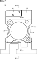
FIG. 2 is a side view of the pressure booster ofFIG. 1 ; -
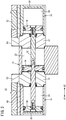
FIG. 3 is a cross sectional view taken along III-III ofFIG. 2 ; -
FIG. 4 is a cross sectional view taken along IV-IV ofFIG. 2 ; -
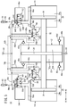
FIG. 5 is a schematic overall diagram illustrating the pressure booster ofFIG. 1 using a circuit diagram; -
FIG. 6 is a cross sectional view of a first pilot valve of the pressure booster ofFIG. 1 ; -
FIG. 7 is a diagram corresponding toFIG. 6 , where the knock pin of the first pilot valve has moved to a different position; -
FIG. 8 is a diagram corresponding toFIG. 6 , where the knock pin of the first pilot valve has moved further to a different position; and -
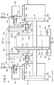
FIG. 9 is a diagram corresponding toFIG. 5 , where the pressure booster has changed from the state ofFIG. 5 to another state. - The pressure booster of the present invention will be described below in detail in connection with preferred embodiments while referring to the accompanying drawings. A
pressure booster 10 according to an embodiment of the invention is installed between a pressurized fluid supply source (compressor; not shown) and an actuator (not shown) that operates with the pressurized fluid whose pressure has been boosted. - As shown in
FIGS. 1 and3 , thepressure booster 10 has a triple cylinder structure including aboosting cylinder 12, afirst driving cylinder 14 disposed at one end of the boosting cylinder 12 (an end on an A1 direction side), and asecond driving cylinder 16 disposed at the other end of the boosting cylinder 12 (an end on an A2 direction side), which are connected in a row. That is, in thepressure booster 10, thefirst driving cylinder 14, the boostingcylinder 12, and thesecond driving cylinder 16 are arranged in this order from the A1 direction to the A2 direction. - A
first cover member 18 in the form of a block is interposed between thefirst driving cylinder 14 and the boostingcylinder 12, and asecond cover member 20 in the form of a block is interposed between the boostingcylinder 12 and thesecond driving cylinder 16. - The boosting
cylinder 12 includes aboosting chamber 22 therein, and thefirst driving cylinder 14 and thesecond driving cylinder 16 include afirst driving chamber 24 and asecond driving chamber 26 therein, respectively. In this case, athird cover member 28 is fixed at an end of thefirst driving cylinder 14 on the A1 side, and thefirst cover member 18 is disposed at an end thereof on the A2 side, thus forming thefirst driving chamber 24. Also, thesecond cover member 20 is disposed at an end of thesecond driving cylinder 16 on the A1 side, and an end thereof on the A2 side is closed by awall 30, thus forming thesecond driving chamber 26. - As shown in
FIG. 3 , apiston rod 32 is provided to pass through thefirst cover member 18, the boostingcylinder 12, and thesecond cover member 20. One end of thepiston rod 32 extends into thefirst driving chamber 24, and the other end of thepiston rod 32 extends into thesecond driving chamber 26. - In the
boosting chamber 22, aboosting piston 34 is coupled to a middle portion of thepiston rod 32. Theboosting chamber 22 is thus partitioned into afirst boosting chamber 22a on the A1 side and asecond boosting chamber 22b on the A2 side (seeFIG. 5 ). In thefirst driving chamber 24, afirst driving piston 36 is coupled at one end of thepiston rod 32. Thefirst driving chamber 24 is thus partitioned into a pressurizingchamber 24a on the A1 side and aback pressure chamber 24b on the A2 side (seeFIG. 5 ). Further, in thesecond driving chamber 26, asecond driving piston 38 is coupled to the other end of thepiston rod 32. Thesecond driving chamber 26 is thus partitioned into a pressurizingchamber 26a on the A2 side and aback pressure chamber 26b on the A1 side (seeFIG. 5 ). Theboosting piston 34, thefirst driving piston 36, and thesecond driving piston 38 are integrally connected through thepiston rod 32. - As shown in
FIG. 1 , the boostingcylinder 12 includes, at an upper portion of the front surface, asupply port 40 to which a pressurized fluid is supplied from a pressurized fluid supply source (not shown). As shown inFIGS. 4 and5 , a fluid supply mechanism is provided in the interiors of the boostingcylinder 12, thefirst cover member 18, and thesecond cover member 20. The fluid supply mechanism communicates with thesupply port 40 and supplies the supplied pressurized fluid into thefirst boosting chamber 22a and thesecond boosting chamber 22b. The fluid supply mechanism includes afirst supply passage 42a that allows thesupply port 40 and thefirst boosting chamber 22a to communicate with each other, and asecond supply passage 42b that allows thesupply port 40 and thesecond boosting chamber 22b to communicate with each other. - The
first supply passage 42a is provided with a firstsupply check valve 42c that permits the flow of fluid from thesupply port 40 to thefirst boosting chamber 22a and blocks the flow of fluid from thefirst boosting chamber 22a to thesupply port 40. Thesecond supply passage 42b is provided with a secondsupply check valve 42d that permits the flow of fluid from thesupply port 40 to thesecond boosting chamber 22b and blocks the flow of fluid from thesecond boosting chamber 22b to thesupply port 40. - As shown in
FIG. 1 , the boostingcylinder 12 includes anoutput port 44 formed in a lower portion of the front surface. Fluid whose pressure is boosted by boosting operation, which will be described later, is outputted from theoutput port 44 to the outside. As shown inFIGS. 4 and5 , a fluid output mechanism is provided in the interiors of the boostingcylinder 12, thefirst cover member 18, and thesecond cover member 20. The fluid output mechanism communicates with theoutput port 44, and outputs, from theoutput port 44, fluid whose pressure has been boosted in thefirst boosting chamber 22a or thesecond boosting chamber 22b. The fluid output mechanism includes afirst output passage 46a that allows thefirst boosting chamber 22a and theoutput port 44 to communicate with each other, and asecond output passage 46b that allows thesecond boosting chamber 22b and theoutput port 44 to communicate with each other. - The
first output passage 46a is provided with a firstoutput check valve 46c that permits the flow of fluid from thefirst boosting chamber 22a to theoutput port 44 and blocks flow of fluid from theoutput port 44 to thefirst boosting chamber 22a. Thesecond output passage 46b is provided with a secondoutput check valve 46d that permits the flow of fluid from thesecond boosting chamber 22b to theoutput port 44 and blocks flow of fluid from theoutput port 44 to thesecond boosting chamber 22b. - Next, a configuration of the operating valves will be described. As shown in
FIG. 1 , thefirst driving cylinder 14 includes, on an upper part thereof, afirst housing 50 having afirst operating valve 48, and thesecond driving cylinder 16 includes, on an upper part thereof, asecond housing 54 having asecond operating valve 52. - As shown in
FIG. 5 , thefirst operating valve 48 has first tofifth ports 56A to 56E as points of connection and switching of passages. Thefirst operating valve 48 is configured so as to be capable of switching between a first position for driving thefirst driving piston 36 and a second position for allowing thefirst driving piston 36 to follow movement of thesecond driving piston 38 being driven. - The
first port 56A is connected to the pressurizingchamber 24a in thefirst driving cylinder 14 through apassage 58a. Thesecond port 56B is connected to theback pressure chamber 24b in thefirst driving cylinder 14 through apassage 58b. Thethird port 56C is connected to thefirst supply passage 42a through apassage 58c. Thefourth port 56D is connected through apassage 58d to afirst silencer 62 having a discharge port. Thefifth port 56E is connected to a midway point of thepassage 58a through apassage 58e. Thepassage 58d has a first fixedorifice 60 interposed therein. - When the
first operating valve 48 is in the first position, thefirst port 56A and thethird port 56C communicate with each other, and thesecond port 56B and thefourth port 56D communicate with each other. Then, the pressurized fluid from thesupply port 40 is supplied into the pressurizingchamber 24a through thepassage 58c andpassage 58a, and the fluid in theback pressure chamber 24b is discharged through thepassage 58b andpassage 58d and through the first fixedorifice 60 and thefirst silencer 62. - When the
first operating valve 48 is in the second position, thefirst port 56A and thefourth port 56D communicate with each other, and thesecond port 56B and thefifth port 56E communicate with each other. Then, part of the fluid in the pressurizingchamber 24a is collected into theback pressure chamber 24b through thepassage 58a,passage 58e, andpassage 58b, and the remaining part is discharged through thepassage 58d and through the first fixedorifice 60 and thefirst silencer 62. - The
first operating valve 48 further includes apilot port 56F for introducing a pilot pressure from asecond pilot valve 74 which will be described later. Thefirst operating valve 48 is in the first position when pressurized fluid (pilot pressure) is being supplied to thepilot port 56F, and it is in the second position when the pressurized fluid (pilot pressure) is not being supplied to thepilot port 56F. - The
second operating valve 52 has first tofifth ports 64A to 64E as points of connection and switching of passages. Thesecond operating valve 52 is configured so as to be capable of switching between a first position for driving thesecond driving piston 38 and a second position for allowing thesecond driving piston 38 to follow movement of thefirst driving piston 36 being driven. - The
first port 64A is connected to the pressurizingchamber 26a in thesecond driving cylinder 16 through apassage 66a. Thesecond port 64B is connected to theback pressure chamber 26b in thesecond driving cylinder 16 through apassage 66b. Thethird port 64C is connected to thesecond supply passage 42b through apassage 66c. Thefourth port 64D is connected through apassage 66d to asecond silencer 70 having a discharge port. Thefifth port 64E is connected to a midway point of thepassage 66a through apassage 66e. Thepassage 66d has a second fixedorifice 68 interposed therein. - When the
second operating valve 52 is in the first position, thefirst port 64A and thethird port 64C communicate with each other, and thesecond port 64B and thefourth port 64D communicate with each other. Then, the pressurized fluid from thesupply port 40 is supplied into the pressurizingchamber 26a through thepassage 66c andpassage 66a, and the fluid in theback pressure chamber 26b is discharged through thepassage 66b andpassage 66d and through the second fixedorifice 68 and thesecond silencer 70. - When the
second operating valve 52 is in the second position, thefirst port 64A and thefourth port 64D communicate with each other, and thesecond port 64B and thefifth port 64E communicate with each other. Then, part of the fluid in the pressurizingchamber 26a is collected into theback pressure chamber 26b through thepassage 66a,passage 66e, andpassage 66b, and the remaining part is discharged through thepassage 66d and through the second fixedorifice 68 and thesecond silencer 70. - The
second operating valve 52 further includes apilot port 64F for introducing a pilot pressure from afirst pilot valve 72 which will be described later. Thesecond operating valve 52 is in the first position when pressurized fluid (pilot pressure) is being supplied to thepilot port 64F, and it is in the second position when the pressurized fluid (pilot pressure) is not being supplied to thepilot port 64F. - Next, a configuration of the pilot valves will be described. The
first pilot valve 72 is provided inside thefirst cover member 18, and thesecond pilot valve 74 is provided inside thesecond cover member 20. - The
first pilot valve 72 has first tofourth ports 76A to 76D. Thefirst pilot valve 72 is configured to be capable of switching between a first position for generating the pilot pressure for thesecond operating valve 52 and a second position for eliminating the pilot pressure. - The
first port 76A is connected to thepilot port 64F of thesecond operating valve 52 through afirst pilot passage 78b. The second port (supply port) 76B is connected to thefirst supply passage 42a through apassage 78a. Thethird port 76C constitutes a discharge port. The fourth port (cooperation port) 76D is connected to afirst port 80A of thesecond pilot valve 74, which will be described later, through abranch passage 82c and asecond pilot passage 82b described later. Further, abranch passage 78c connecting to afourth port 80D of thesecond pilot valve 74, which will be described later, branches off from thefirst pilot passage 78b. - When the
first pilot valve 72 is in the first position, thefirst port 76A and thesecond port 76B communicate with each other. Then, the pressurized fluid from thesupply port 40 is supplied to thepilot port 64F of thesecond operating valve 52 through thepassage 78a and thefirst pilot passage 78b, and the pressurized fluid is also supplied to thefourth port 80D of the second pilot valve 74 (described later) through thebranch passage 78c branching off from thefirst pilot passage 78b. - When the
first pilot valve 72 is in the second position, thefirst port 76A and thethird port 76C communicate with each other. Then, the pressurized fluid that has been being supplied to thepilot port 64F of thesecond operating valve 52 is discharged through thefirst pilot passage 78b, and the pressurized fluid supplied to thefourth port 80D of thesecond pilot valve 74 is discharged through thebranch passage 78c andfirst pilot passage 78b. - The
second pilot valve 74 has first tofourth ports 80A to 80D. Thesecond pilot valve 74 is configured to be capable of switching between a first position for generating the pilot pressure for thefirst operating valve 48 and a second position for eliminating the pilot pressure. - The
first port 80A is connected to thepilot port 56F of thefirst operating valve 48 through thesecond pilot passage 82b. The second port (supply port) 80B is connected to thesecond supply passage 42b through apassage 82a. The third port 80C constitutes a discharge port. Thefourth port 80D (cooperation port) is connected to thefirst port 76A of thefirst pilot valve 72 through thebranch passage 78c and thefirst pilot passage 78b. Further, thebranch passage 82c connecting to thefourth port 76D of thefirst pilot valve 72 branches off from thesecond pilot passage 82b. - When the
second pilot valve 74 is in the first position, thefirst port 80A and thesecond port 80B communicate with each other. Then, the pressurized fluid from thesupply port 40 is supplied to thepilot port 56F of thefirst operating valve 48 through thepassage 82a andsecond pilot passage 82b, and the pressurized fluid is also supplied to thefourth port 76D of thefirst pilot valve 72 through thebranch passage 82c branching off from thesecond pilot passage 82b. - When the
second pilot valve 74 is in the second position, thefirst port 80A and the third port 80C communicate with each other. Then, the pressurized fluid that has been being supplied to thepilot port 56F of thefirst operating valve 48 is discharged through thesecond pilot passage 82b, and the pressurized fluid supplied to thefourth port 76D of thefirst pilot valve 72 is discharged through thebranch passage 82c andsecond pilot passage 82b. - Now, referring to
FIGS. 6 to 8 , a specific structure of thefirst pilot valve 72 will be described. Thesecond pilot valve 74 has the same structure as thefirst pilot valve 72, and so it will not be described herein. - The
first pilot valve 72 includes avalve seat 86 accommodated in avalve container hole 84 formed in thefirst cover member 18, avalve seat retainer 88, and aknock pin 90. Thevalve container hole 84 is closed on the side of the boostingcylinder 12 and opens on the side of thefirst driving cylinder 14. Thevalve container hole 84 includes, at the closed end, a large-diameter hole portion 84a, and thefourth port 76D communicates with this large-diameter hole portion 84a. - The
valve container hole 84 further has a small-diameter hole portion 84b connecting to the large-diameter hole portion 84a, and a medium-diameter hole portion 84c disposed on the opening side of the valve container hole and connecting to the small-diameter hole portion 84b. Thefirst port 76A, thesecond port 76B, and thethird port 76C communicate with the small-diameter hole portion 84b of thevalve container hole 84. Of these three ports, thesecond port 76B is located closest to thefourth port 76D, and thethird port 76C is located farthest from thefourth port 76D. - The
valve seat 86 having a thin-walled cylindrical shape, and thevalve seat retainer 88 having a thick-walled cylindrical shape, are inserted and fitted into the small-diameter hole portion 84b of thevalve container hole 84. Thevalve seat retainer 88 includes one end surface located at one end in the axial direction and another end surface located at the other end in the axial direction, the one end surface facing toward theback pressure chamber 24b of thefirst driving cylinder 14, the other end surface abutting against thevalve seat 86. Asnap ring 92 abutting on thevalve seat retainer 88 is fixed to the medium-diameter hole portion 84c of thevalve container hole 84. Thevalve seat 86 and thevalve seat retainer 88 are thus positioned and fixed in the axial direction inside thevalve container hole 84. Thevalve seat 86 is engaged and locked with a step formed at a middle position of the small-diameter hole portion 84b. - An
annular groove 86a facing thefirst port 76A is formed in the outer periphery of a middle portion of thevalve seat 86 in the axial direction, and anannular recess 86b facing thethird port 76C is formed in the outer periphery of an end of thevalve seat 86 in the axial direction on a side that abuts on thevalve seat retainer 88. Theannular groove 86a of thevalve seat 86 communicates with the inner peripheral side of thevalve seat 86 through a first throughhole 86c that penetrates through thevalve seat 86 in the radial direction, and theannular recess 86b of thevalve seat 86 communicates with the inner peripheral side of thevalve seat 86 through a second throughhole 86d that penetrates through thevalve seat 86 in the radial direction. - A
first seal member 94a and asecond seal member 94b that abut against the small-diameter hole portion 84b of thevalve container hole 84 are fitted into grooves formed in the outer peripheral surface of thevalve seat 86. Thefirst seal member 94a prevents thefirst port 76A and thesecond port 76B from communicating with each other through the gap between thevalve seat 86 and thevalve container hole 84, and thesecond seal member 94b prevents thefirst port 76A and thethird port 76C from communicating with each other through the gap between thevalve seat 86 and thevalve container hole 84. - A
third seal member 96a abutting against the small-diameter hole portion 84b of thevalve container hole 84 is fitted into a groove formed in the outer peripheral surface of thevalve seat retainer 88, and afourth seal member 96b in sliding contact with theknock pin 90 is fitted into a groove formed in the inner peripheral surface of thevalve seat retainer 88. Thethird seal member 96a and thefourth seal member 96b provide a seal between thethird port 76C and theback pressure chamber 24b of thefirst driving cylinder 14. - The
knock pin 90 has a large-diameter shaft portion 90a, a medium-diameter shaft portion 90b, and a small-diameter shaft portion 90c. The large-diameter shaft portion 90a is inserted and fitted into the small-diameter hole portion 84b of thevalve container hole 84. The medium-diameter shaft portion 90b is inserted and fitted into the inside of thevalve seat 86 in such a manner that part of theshaft portion 90b protrudes from thevalve seat 86, and the part protruding from thevalve seat 86 faces the small-diameter hole portion 84b of thevalve container hole 84 at a certain interval in the radial direction. The small-diameter shaft portion 90c is inserted and fitted into the inside of thevalve seat retainer 88. - A
first packing 98a in sliding contact with the small-diameter hole portion 84b of thevalve container hole 84 is fitted into a groove formed in the large-diameter shaft portion 90a of theknock pin 90. Thefirst packing 98a provides a seal between thesecond port 76B and thefourth port 76D. Asecond packing 98b and athird packing 98c that can be in sliding contact with the inner peripheral surface of thevalve seat 86 are fitted into grooves formed in the medium-diameter shaft portion 90b of theknock pin 90. The outer periphery of the medium-diameter shaft portion 90b of theknock pin 90 has, formed therein, anannular groove 90d between the portion where thesecond packing 98b is fitted and the portion where thethird packing 98c is fitted. - The
knock pin 90 can slide between a position where its end on the large-diameter shaft portion 90a side contacts the bottom surface (closed end surface) of thevalve container hole 84 and a position where astep surface 90e between the medium-diameter shaft portion 90b and the small-diameter shaft portion 90c contacts the end surface of thevalve seat retainer 88. When theknock pin 90 contacts the end surface of thevalve seat retainer 88, the length that the small-diameter shaft portion 90c of theknock pin 90 projects into theback pressure chamber 24b of the first driving cylinder 14 (hereinafter referred to as "projecting length of the knock pin") becomes the maximum. Thefirst driving piston 36 comes in contact with the end of theknock pin 90 on its small-diameter shaft portion 90c side and presses theknock pin 90 in the direction toward the bottom surface of thevalve container hole 84. - The
annular groove 90d of theknock pin 90 communicates with theannular groove 86a through the first throughhole 86c in thevalve seat 86, irrespective of the projecting length of theknock pin 90. In other words, theannular groove 90d of theknock pin 90 always communicates with thefirst port 76A irrespective of the position of theknock pin 90. Further, thesecond port 76B always communicates with the gap formed between the medium-diameter shaft portion 90b of theknock pin 90 and the small-diameter hole portion 84b of thevalve container hole 84. - When the projecting length of the
knock pin 90 is large, thesecond packing 98b contacts the inner surface of thevalve seat 86, and thethird packing 98c separates away from the inner surface of the valve seat 86 (seeFIG. 6 ). Accordingly, thefirst port 76A communicates with thethird port 76C through the gap between the inner surface of thevalve seat 86 and theknock pin 90 including theannular groove 90d of theknock pin 90, and through the second throughhole 86d and theannular recess 86b of thevalve seat 86. - When the
first driving piston 36 comes in contact with theknock pin 90 and the projecting length of theknock pin 90 becomes somewhat shorter than in the state described above, then both thesecond packing 98b and thethird packing 98c contact the inner surface of the valve seat 86 (seeFIG. 7 ). Accordingly, thefirst port 76A does not communicate with either of thesecond port 76B and thethird port 76C. - When the projecting length of the
knock pin 90 is small, thesecond packing 98b separates away from the inner surface of thevalve seat 86 and thethird packing 98c contacts the inner surface of the valve seat 86 (seeFIG. 8 ). Accordingly, thefirst port 76A communicates with thesecond port 76B through the gap between the inner surface of thevalve seat 86 and theknock pin 90 including theannular groove 90d of theknock pin 90 and through the gap formed between the medium-diameter shaft portion 90b of theknock pin 90 and the small-diameter hole portion 84b of thevalve container hole 84. - When the pressurized fluid is supplied into the
fourth port 76D, then theknock pin 90 is pushed in such a direction that its projecting length increases. This is because the area (pressure receiving area) on which the fluid pressure at thefourth port 76D acts in the direction to increase the projecting length of theknock pin 90 is larger than the area (pressure receiving area) on which the fluid pressure at thesecond port 76B acts in the direction to reduce the projecting length of theknock pin 90. - On the other hand, when the pressurized fluid is not supplied into the
fourth port 76D, then theknock pin 90 is pressed in such a direction that its projecting length decreases. This is because the fluid pressure at thefourth port 76D acting in the direction to increase the projecting length of theknock pin 90 disappears, while the fluid pressure at thesecond port 76B acting in the direction to reduce the projecting length of theknock pin 90 is maintained. - The
pressure booster 10 of the first embodiment of the present invention is configured basically as described above. Next, its operations, and functions and effects will be described. As shown inFIG. 5 , it is assumed that, in the initial position, thefirst operating valve 48 has switched to the second position, thesecond operating valve 52 has switched to the first position, and the boostingpiston 34 is positioned close to the center in the boostingchamber 22. In the description below, in order to distinguish the knock pin of thefirst pilot valve 72 and the knock pin of thesecond pilot valve 74, the former will be referred to as "knock pin 90-1" and the latter will be referred to as "knock pin 90-2". Further, in order to distinguish the valve container hole of thefirst pilot valve 72 and the valve container hole of thesecond pilot valve 74, the former will be referred to as "valve container hole 84-1" and the latter will be referred to as "valve container hole 84-2". - In this initial position, the pressurized fluid is supplied from the pressurized fluid supply source to the
supply port 40, and then the pressurized fluid flows into thefirst supply passage 42a and thesecond supply passage 42b. Then, the pressurized fluid is introduced into the first boostingchamber 22a and the second boostingchamber 22b of the boostingcylinder 12 through the firstsupply check valve 42c and the secondsupply check valve 42d. - Part of the pressurized fluid supplied from the
supply port 40 is supplied into the pressurizingchamber 26a in thesecond driving cylinder 16 through thepassage 66c, thesecond operating valve 52 being in the first position, and thepassage 66a. The pressurized fluid supplied into the pressurizingchamber 26a drives thesecond driving piston 38 in the A1 direction. Then, the boostingpiston 34, which is integrally coupled to thesecond driving piston 38, slides to boost the pressure of the pressurized fluid in the first boostingchamber 22a of the boostingcylinder 12. The boosted pressurized fluid is guided through thefirst output passage 46a and the firstoutput check valve 46c to theoutput port 44 and is outputted therefrom. - On the other hand, the
first driving piston 36, which is integrally coupled to thesecond driving piston 38, slides, and then the volume of the pressurizingchamber 24a in thefirst driving cylinder 14 becomes small. Since thefirst operating valve 48 is in the second position, part of the pressurized fluid in the pressurizingchamber 24a is collected into theback pressure chamber 24b through thepassage 58a,passage 58e, andpassage 58b, and the remaining part thereof is discharged through thepassage 58d. - As explained earlier, in the process in which the boosting
piston 34 moves from the initial position to a certain distance in the A1 direction, thefirst pilot valve 72 is in the first position and so the pressurized fluid from thesupply port 40 is being supplied to thefourth port 80D of thesecond pilot valve 74 through thefirst pilot valve 72. On the other hand, thesecond pilot valve 74 is in the second position, and so the pressurized fluid is not supplied to thefourth port 76D of thefirst pilot valve 72. Accordingly, in thefirst pilot valve 72, the knock pin 90-1 is urged in the direction to reduce the projecting length of the knock pin 90-1, and therefore thefirst pilot valve 72 is stably kept in the first position. On the other hand, in thesecond pilot valve 74, the knock pin 90-2 is urged in the direction to increase the projecting length of the knock pin 90-2, and therefore thesecond pilot valve 74 is stably kept in the second position. - Then, as shown in
FIG. 9 , in the vicinity of the stroke end of the displacement of the boostingpiston 34 in the A1 direction, thesecond driving piston 38 comes in contact with the knock pin 90-2 of thesecond pilot valve 74. The knock pin 90-2 is pushed and displaced by thesecond driving piston 38, causing thefirst port 80A and thesecond port 80B of thesecond pilot valve 74 to communicate with each other. Then, the pressurized fluid from thesupply port 40 is supplied to thepilot port 56F of thefirst operating valve 48 through thesecond pilot passage 82b, and also supplied to thefourth port 76D of thefirst pilot valve 72 through thebranch passage 82c. This causes thefirst operating valve 48 to switch to the first position and thefirst pilot valve 72 to switch to the second position. - When the
first pilot valve 72 has switched to the second position, the pressurized fluid that was being supplied to thepilot port 64F of thesecond operating valve 52 flows through thefirst pilot passage 78b and is then discharged from thethird port 76C of thefirst pilot valve 72. This causes thesecond operating valve 52 to switch to the second position. - Further, when the
first pilot valve 72 has switched to the second position, the pressurized fluid that was being supplied to thefourth port 80D of thesecond pilot valve 74 is discharged from thethird port 76C of thefirst pilot valve 72 through thebranch passage 78c and thefirst pilot passage 78b. Accordingly, in thesecond pilot valve 74, the fluid pressure acts in the direction to reduce the projecting length of the knock pin 90-2. Then, the knock pin 90-2, which has been pushed by thesecond driving piston 38 and displaced to a position at which thefirst port 80A and thesecond port 80B of thesecond pilot valve 74 communicate with each other, is further subjected to the fluid pressure, and is kept in the position in which the knock pin 90-2 abuts against the bottom surface of the valve container hole 84-2. That is, thesecond pilot valve 74 is stably kept in the first position. The state in which thesecond pilot valve 74 is kept in the first position is maintained until thefirst driving piston 36 is driven in the A2 direction and displaces the knock pin 90-1, as will be described later. - This time, part of the pressurized fluid supplied from the
supply port 40 is supplied into the pressurizingchamber 24a in thefirst driving cylinder 14 through thepassage 58c, thefirst operating valve 48 being in the first position, and thepassage 58a. The pressurized fluid supplied into the pressurizingchamber 24a drives thefirst driving piston 36 in the A2 direction. This causes the boostingpiston 34, which is integrally coupled to thefirst driving piston 36, to slide to boost the pressure of the pressurized fluid in the second boostingchamber 22b of the boostingcylinder 12. The boosted pressurized fluid is guided through thesecond output passage 46b and the secondoutput check valve 46d to theoutput port 44 and is outputted therefrom. - On the other hand, the
second driving piston 38, which is integrally coupled to thefirst driving piston 36, slides, and then the volume of the pressurizingchamber 26a in thesecond driving cylinder 16 becomes small. Since thesecond operating valve 52 is in the second position, part of the pressurized fluid in the pressurizingchamber 26a is collected into theback pressure chamber 26b through thepassage 66a,passage 66e, andpassage 66b, and the remaining part thereof is discharged through thepassage 66d. - Then, in the vicinity of the stroke end of the displacement of the boosting
piston 34 in the A2 direction, thefirst driving piston 36 comes in contact with the knock pin 90-1 of thefirst pilot valve 72. The knock pin 90-1 is pressed and displaced by thefirst driving piston 36, causing thefirst port 76A and thesecond port 76B of thefirst pilot valve 72 to communicate with each other. Then, the pressurized fluid from thesupply port 40 is supplied to thepilot port 64F of thesecond operating valve 52 through thefirst pilot passage 78b, and also supplied to thefourth port 80D of thesecond pilot valve 74 through thebranch passage 78c. This causes thesecond operating valve 52 to switch to the first position and thesecond pilot valve 74 to switch to the second position. - When the
second pilot valve 74 has switched to the second position, the pressurized fluid that was being supplied to thepilot port 56F of thefirst operating valve 48 is discharged from the third port 80C of thesecond pilot valve 74 through thesecond pilot passage 82b. This causes thefirst operating valve 48 to switch to the second position. - Further, when the
second pilot valve 74 has switched to the second position, the pressurized fluid that was being supplied to thefourth port 76D of thefirst pilot valve 72 is discharged from the third port 80C of thesecond pilot valve 74 through thebranch passage 82c and thesecond pilot passage 82b. Accordingly, in thefirst pilot valve 72, the fluid pressure acts in the direction to reduce the projecting length of the knock pin 90-1. Then, the knock pin 90-1, which was pushed by thefirst driving piston 36 and displaced to a position at which thefirst port 76A and thesecond port 76B of thefirst pilot valve 72 communicate with each other, is further subjected to the fluid pressure, and is kept in the position in which the knock pin 90-1 abuts on the bottom surface of the valve container hole 84-1. That is, thefirst pilot valve 72 is stably kept in the first position. The state in which thefirst pilot valve 72 is kept in the first position is maintained until thesecond driving piston 38 is driven again in the A1 direction and displaces the knock pin 90-2. After this, in the same way, the boostingpiston 34 repeats the reciprocating movement and the boosted pressurized fluid is continuously outputted from theoutput port 44. - According to the
pressure booster 10 of the embodiment, the knock pin 90-1 is pushed by thefirst driving piston 36 and displaced to such a position as to cause thefirst port 76A and thesecond port 76B of thefirst pilot valve 72 to communicate with each other, then the knock pin 90-1 is further pushed by a certain fluid pressure to a position where the knock pin 90-1 abuts on the bottom surface of the valve container hole 84-1, and as a result, the knock pin 90-1 can be kept in this position. In the same way, after the knock pin 90-2 is pushed by thesecond driving piston 38 and displaced to such a position as to cause thefirst port 80A and thesecond port 80B of thesecond pilot valve 74 to communicate with each other, the knock pin 90-2 is further pushed by a certain fluid pressure to a position where the knock pin 90-2 abuts on the bottom surface of the valve container hole 84-2, and as a result, the knock pin 90-2 can be kept in this position. - Further, the
first operating valve 48 switches to the first position when the pilot pressure is supplied from thesecond pilot valve 74 configured to switch its position in cooperation with thefirst pilot valve 72, and thefirst operating valve 48 switches to the second position when the supply of the pilot pressure from thesecond pilot valve 74 disappears. In the same way, thesecond operating valve 52 switches to the first position when the pilot pressure is supplied from thefirst pilot valve 72 configured to switch its position in cooperation with thesecond pilot valve 74, and thesecond operating valve 52 switches to the second position when the supply of the pilot pressure from thefirst pilot valve 72 disappears. Thus, thefirst operating valve 48 and thesecond operating valve 52 operate stably and switch at the same time. - Further, part of the fluid that was supplied into the pressurizing
chamber 24a in order to drive thefirst driving piston 36 is collected into theback pressure chamber 24b when thefirst driving piston 36 is driven in conjunction with movement of thesecond driving piston 38, and thus it is possible to reduce the consumption of the pressurized fluid. In the same way, part of the fluid that was supplied into the pressurizingchamber 26a in order to drive thesecond driving piston 38 is collected into theback pressure chamber 26b when thesecond driving piston 38 is driven in conjunction with movement of thefirst driving piston 36, and thus it is possible to reduce the consumption of the pressurized fluid. - The pressure booster according to the present invention is not limited to the embodiments described above, but can of course adopt various configurations without departing from the essence and gist of the present invention.
Claims (5)
- A pressure booster in which driving cylinders (14, 16) are provided respectively on both sides of a boosting cylinder (12), the pressure booster comprising:a pair of pilot valves (72, 74) each including a knock pin (90) with which a piston (36, 38) of a corresponding one of the driving cylinders comes in contact at a travel end of the piston; and a pair of operating valves (48, 52) each configured to switch a state of supply of a pressurized fluid from a pressurized fluid supply source into a pressurizing chamber (24a, 26a) of a corresponding one of the driving cylinders,wherein, when one or another of the pilot valves switches to a first position by the knock pin of the pilot valve being pushed by the corresponding piston, then a state of supply of the pressurized fluid to the pair of operating valves is switched and a certain fluid pressure acts on the knock pin so as to hold the pilot valve in the first position.
- The pressure booster according to claim 1, wherein a position of another of the operating valves is switched depending on presence or absence of a pilot pressure supplied from the one of the pilot valves, and a position of one of the operating valves is switched depending on presence or absence of a pilot pressure supplied from the other of the pilot valves.
- The pressure booster according to claim 1, wherein the one of the pilot valves has a supply port to which the pressurized fluid is always supplied and a cooperation port to which the pressurized fluid is supplied through the other of the pilot valves, and the other of the pilot valves has a supply port to which the pressurized fluid is always supplied and a cooperation port to which the pressurized fluid is supplied through the one of the pilot valves, and wherein, when the pressurized fluid is supplied to the cooperation port of the one or the other of the pilot valves, then the knock pin of the pilot valve is urged in a direction in which the pilot valve moves toward a second position, and when the pressurized fluid is not supplied to the cooperation port, then the certain fluid pressure acts on the knock pin.
- The pressure booster according to claim 3, wherein, when the one of the pilot valves is in the first position, a pilot pressure is supplied to another of the operating valves and the pressurized fluid is supplied to the cooperation port of the other of the pilot valves, and when the other of the pilot valves is in the first position, the pilot pressure is supplied to one of the operating valves and the pressurized fluid is supplied to the cooperation port of the one of the pilot valves.
- The pressure booster according to claim 1, wherein each of the operating valves switches between a state that the pressurized fluid is supplied into the pressurizing chamber of the corresponding one of the driving cylinders and a pressurized fluid in a back pressure chamber (24b, 26b) of the driving cylinder is discharged, and a state that part of the pressurized fluid in the pressurizing chamber of the driving cylinder is collected into the back pressure chamber of the driving cylinder.
Applications Claiming Priority (2)
| Application Number | Priority Date | Filing Date | Title |
|---|---|---|---|
| JP2018152815 | 2018-08-15 | ||
| PCT/JP2019/028933 WO2020036046A1 (en) | 2018-08-15 | 2019-07-24 | Pressure booster |
Publications (4)
| Publication Number | Publication Date |
|---|---|
| EP3839265A1 true EP3839265A1 (en) | 2021-06-23 |
| EP3839265A4 EP3839265A4 (en) | 2022-04-20 |
| EP3839265B1 EP3839265B1 (en) | 2025-05-07 |
| EP3839265B8 EP3839265B8 (en) | 2025-06-11 |
Family
ID=69524841
Family Applications (1)
| Application Number | Title | Priority Date | Filing Date |
|---|---|---|---|
| EP19849370.2A Active EP3839265B8 (en) | 2018-08-15 | 2019-07-24 | Pressure booster |
Country Status (8)
| Country | Link |
|---|---|
| EP (1) | EP3839265B8 (en) |
| JP (1) | JP7314463B2 (en) |
| KR (1) | KR102523626B1 (en) |
| CN (1) | CN112567140B (en) |
| BR (1) | BR112021002800A2 (en) |
| MX (1) | MX2021001767A (en) |
| TW (1) | TWI704292B (en) |
| WO (1) | WO2020036046A1 (en) |
Families Citing this family (6)
| Publication number | Priority date | Publication date | Assignee | Title |
|---|---|---|---|---|
| EP4617507A3 (en) * | 2021-03-31 | 2025-11-12 | Eagle Industry Co., Ltd. | Fluid circuit |
| CN113374744B (en) * | 2021-07-06 | 2022-05-06 | 中煤科工集团重庆研究院有限公司 | Continuous conveying drill rod hydraulic system with locking function |
| CN113404731B (en) * | 2021-07-06 | 2022-05-20 | 中煤科工集团重庆研究院有限公司 | Synchronous continuous conveying drill rod hydraulic system with locking function |
| CN113374746B (en) * | 2021-07-06 | 2022-05-20 | 中煤科工集团重庆研究院有限公司 | Synchronous continuous conveying drill rod hydraulic system |
| CN113374745B (en) * | 2021-07-06 | 2022-05-20 | 中煤科工集团重庆研究院有限公司 | Hydraulic system for continuously conveying drill rods |
| CN120701786A (en) * | 2025-08-15 | 2025-09-26 | 新立行科技浙江有限公司 | A lossless external boost valve |
Family Cites Families (15)
| Publication number | Priority date | Publication date | Assignee | Title |
|---|---|---|---|---|
| US2296647A (en) * | 1941-02-28 | 1942-09-22 | Racine Tool & Machine Company | Hydraulic pressure booster |
| US2942553A (en) * | 1958-05-09 | 1960-06-28 | Gen Motors Corp | Gas driven hydraulic actuator |
| DE1528583A1 (en) * | 1965-05-20 | 1970-01-29 | Stahl U Appbau Hans Leffer Gmb | Hydraulically or pneumatically continuously operated piston drive with reciprocating movement, especially double-acting pressure intensifier |
| JPS4033392Y1 (en) * | 1965-07-23 | 1965-11-22 | ||
| JPS6043184A (en) * | 1983-08-17 | 1985-03-07 | Nippon Gurei Kk | Reciprocating pump device |
| JP3368052B2 (en) | 1994-07-11 | 2003-01-20 | 甲南電機株式会社 | Empty intensifier |
| JPH10267002A (en) * | 1997-03-25 | 1998-10-06 | Smc Corp | Pressure booster |
| JP4301310B2 (en) * | 2007-03-12 | 2009-07-22 | Smc株式会社 | Booster |
| CN201347907Y (en) * | 2008-12-23 | 2009-11-18 | 大连海事大学 | Gas-saving type gas supercharger by utilizing double driving pistons |
| MX2014015410A (en) * | 2012-06-18 | 2016-03-21 | Flowserve Man Co | Fluid intensifier for a dry gas seal system. |
| TWM452245U (en) * | 2012-12-28 | 2013-05-01 | Kinyao Entpr Co Ltd | Hydraulic booster pump structure |
| US9926947B2 (en) * | 2014-05-09 | 2018-03-27 | Montana Hydraulics, LLC | Air-to-hydraulic fluid pressure amplifier |
| TWI595159B (en) * | 2014-12-31 | 2017-08-11 | High-pressure cylinder and booster system | |
| JP2017164945A (en) | 2016-03-15 | 2017-09-21 | 三菱製紙株式会社 | Coated paper for industrial inkjet printer and manufacturing method therefor |
| JP6572872B2 (en) * | 2016-11-22 | 2019-09-11 | Smc株式会社 | Booster |
-
2019
- 2019-07-24 JP JP2020537395A patent/JP7314463B2/en active Active
- 2019-07-24 CN CN201980053314.9A patent/CN112567140B/en active Active
- 2019-07-24 BR BR112021002800-5A patent/BR112021002800A2/en not_active IP Right Cessation
- 2019-07-24 WO PCT/JP2019/028933 patent/WO2020036046A1/en not_active Ceased
- 2019-07-24 KR KR1020217006954A patent/KR102523626B1/en active Active
- 2019-07-24 EP EP19849370.2A patent/EP3839265B8/en active Active
- 2019-07-24 MX MX2021001767A patent/MX2021001767A/en unknown
- 2019-08-15 TW TW108129127A patent/TWI704292B/en active
Also Published As
| Publication number | Publication date |
|---|---|
| EP3839265A4 (en) | 2022-04-20 |
| CN112567140B (en) | 2023-01-24 |
| KR102523626B1 (en) | 2023-04-19 |
| EP3839265B8 (en) | 2025-06-11 |
| TWI704292B (en) | 2020-09-11 |
| BR112021002800A2 (en) | 2021-05-04 |
| JP7314463B2 (en) | 2023-07-26 |
| MX2021001767A (en) | 2021-04-19 |
| CN112567140A (en) | 2021-03-26 |
| WO2020036046A1 (en) | 2020-02-20 |
| KR20210040136A (en) | 2021-04-12 |
| JPWO2020036046A1 (en) | 2021-08-26 |
| EP3839265B1 (en) | 2025-05-07 |
| TW202016436A (en) | 2020-05-01 |
Similar Documents
| Publication | Publication Date | Title |
|---|---|---|
| EP3839265B1 (en) | Pressure booster | |
| US6325102B1 (en) | Servo driving pilot-type solenoid valve | |
| KR102590234B1 (en) | Solenoid proportional valve | |
| KR102247489B1 (en) | Pressure intensifier | |
| CN110573750B (en) | Supercharging device and cylinder device having the same | |
| US6581624B1 (en) | Automatic pressurized fluid switching device | |
| CN114060329A (en) | Pneumatic booster | |
| CN108180294B (en) | Multiway valve and method for operating the same | |
| JP2000274403A (en) | Cylinder device | |
| JPH10267002A (en) | Pressure booster | |
| EP0551985A1 (en) | Double action, dual speed and force hydraulic actuators | |
| EP3263958B1 (en) | Pilot valve | |
| JP2605521Y2 (en) | Diaphragm pump | |
| JPS63243464A (en) | Booster | |
| JP2526615Y2 (en) | Air driven pump | |
| JPH0527681Y2 (en) | ||
| JP2676111B2 (en) | Fluid pressure continuously operated reciprocating actuator | |
| JPH049445Y2 (en) | ||
| JP2001116007A (en) | Pilot operation check valve | |
| JPH06272773A (en) | Fluid change-over valve | |
| JPH0344018B2 (en) | ||
| JPH08277805A (en) | Valve device and cylinder driving device using the same |
Legal Events
| Date | Code | Title | Description |
|---|---|---|---|
| STAA | Information on the status of an ep patent application or granted ep patent |
Free format text: STATUS: THE INTERNATIONAL PUBLICATION HAS BEEN MADE |
|
| PUAI | Public reference made under article 153(3) epc to a published international application that has entered the european phase |
Free format text: ORIGINAL CODE: 0009012 |
|
| STAA | Information on the status of an ep patent application or granted ep patent |
Free format text: STATUS: REQUEST FOR EXAMINATION WAS MADE |
|
| 17P | Request for examination filed |
Effective date: 20210129 |
|
| AK | Designated contracting states |
Kind code of ref document: A1 Designated state(s): AL AT BE BG CH CY CZ DE DK EE ES FI FR GB GR HR HU IE IS IT LI LT LU LV MC MK MT NL NO PL PT RO RS SE SI SK SM TR |
|
| DAV | Request for validation of the european patent (deleted) | ||
| DAX | Request for extension of the european patent (deleted) | ||
| A4 | Supplementary search report drawn up and despatched |
Effective date: 20220323 |
|
| RIC1 | Information provided on ipc code assigned before grant |
Ipc: F04B 9/135 20060101ALI20220318BHEP Ipc: F04B 9/115 20060101ALI20220318BHEP Ipc: F15B 3/00 20060101AFI20220318BHEP |
|
| GRAP | Despatch of communication of intention to grant a patent |
Free format text: ORIGINAL CODE: EPIDOSNIGR1 |
|
| STAA | Information on the status of an ep patent application or granted ep patent |
Free format text: STATUS: GRANT OF PATENT IS INTENDED |
|
| INTG | Intention to grant announced |
Effective date: 20250109 |
|
| P01 | Opt-out of the competence of the unified patent court (upc) registered |
Free format text: CASE NUMBER: APP_7710/2025 Effective date: 20250214 |
|
| GRAS | Grant fee paid |
Free format text: ORIGINAL CODE: EPIDOSNIGR3 |
|
| GRAA | (expected) grant |
Free format text: ORIGINAL CODE: 0009210 |
|
| STAA | Information on the status of an ep patent application or granted ep patent |
Free format text: STATUS: THE PATENT HAS BEEN GRANTED |
|
| AK | Designated contracting states |
Kind code of ref document: B1 Designated state(s): AL AT BE BG CH CY CZ DE DK EE ES FI FR GB GR HR HU IE IS IT LI LT LU LV MC MK MT NL NO PL PT RO RS SE SI SK SM TR |
|
| REG | Reference to a national code |
Ref country code: GB Ref legal event code: FG4D |
|
| REG | Reference to a national code |
Ref country code: CH Ref legal event code: PK Free format text: BERICHTIGUNG B8 Ref country code: CH Ref legal event code: EP |
|
| REG | Reference to a national code |
Ref country code: DE Ref legal event code: R096 Ref document number: 602019069751 Country of ref document: DE |
|
| REG | Reference to a national code |
Ref country code: IE Ref legal event code: FG4D |
|
| RAP4 | Party data changed (patent owner data changed or rights of a patent transferred) |
Owner name: SMC CORPORATION |
|
| REG | Reference to a national code |
Ref country code: NL Ref legal event code: MP Effective date: 20250507 |
|
| PG25 | Lapsed in a contracting state [announced via postgrant information from national office to epo] |
Ref country code: PT Free format text: LAPSE BECAUSE OF FAILURE TO SUBMIT A TRANSLATION OF THE DESCRIPTION OR TO PAY THE FEE WITHIN THE PRESCRIBED TIME-LIMIT Effective date: 20250908 Ref country code: FI Free format text: LAPSE BECAUSE OF FAILURE TO SUBMIT A TRANSLATION OF THE DESCRIPTION OR TO PAY THE FEE WITHIN THE PRESCRIBED TIME-LIMIT Effective date: 20250507 Ref country code: ES Free format text: LAPSE BECAUSE OF FAILURE TO SUBMIT A TRANSLATION OF THE DESCRIPTION OR TO PAY THE FEE WITHIN THE PRESCRIBED TIME-LIMIT Effective date: 20250507 |
|
| PGFP | Annual fee paid to national office [announced via postgrant information from national office to epo] |
Ref country code: DE Payment date: 20250723 Year of fee payment: 7 |
|
| REG | Reference to a national code |
Ref country code: LT Ref legal event code: MG9D |
|
| PG25 | Lapsed in a contracting state [announced via postgrant information from national office to epo] |
Ref country code: NO Free format text: LAPSE BECAUSE OF FAILURE TO SUBMIT A TRANSLATION OF THE DESCRIPTION OR TO PAY THE FEE WITHIN THE PRESCRIBED TIME-LIMIT Effective date: 20250807 Ref country code: GR Free format text: LAPSE BECAUSE OF FAILURE TO SUBMIT A TRANSLATION OF THE DESCRIPTION OR TO PAY THE FEE WITHIN THE PRESCRIBED TIME-LIMIT Effective date: 20250808 |
|
| PG25 | Lapsed in a contracting state [announced via postgrant information from national office to epo] |
Ref country code: PL Free format text: LAPSE BECAUSE OF FAILURE TO SUBMIT A TRANSLATION OF THE DESCRIPTION OR TO PAY THE FEE WITHIN THE PRESCRIBED TIME-LIMIT Effective date: 20250507 Ref country code: NL Free format text: LAPSE BECAUSE OF FAILURE TO SUBMIT A TRANSLATION OF THE DESCRIPTION OR TO PAY THE FEE WITHIN THE PRESCRIBED TIME-LIMIT Effective date: 20250507 |
|
| REG | Reference to a national code |
Ref country code: AT Ref legal event code: MK05 Ref document number: 1792737 Country of ref document: AT Kind code of ref document: T Effective date: 20250507 |
|
| PG25 | Lapsed in a contracting state [announced via postgrant information from national office to epo] |
Ref country code: BG Free format text: LAPSE BECAUSE OF FAILURE TO SUBMIT A TRANSLATION OF THE DESCRIPTION OR TO PAY THE FEE WITHIN THE PRESCRIBED TIME-LIMIT Effective date: 20250507 |
|
| PG25 | Lapsed in a contracting state [announced via postgrant information from national office to epo] |
Ref country code: HR Free format text: LAPSE BECAUSE OF FAILURE TO SUBMIT A TRANSLATION OF THE DESCRIPTION OR TO PAY THE FEE WITHIN THE PRESCRIBED TIME-LIMIT Effective date: 20250507 |
|
| PG25 | Lapsed in a contracting state [announced via postgrant information from national office to epo] |
Ref country code: AT Free format text: LAPSE BECAUSE OF FAILURE TO SUBMIT A TRANSLATION OF THE DESCRIPTION OR TO PAY THE FEE WITHIN THE PRESCRIBED TIME-LIMIT Effective date: 20250507 |
|
| PG25 | Lapsed in a contracting state [announced via postgrant information from national office to epo] |
Ref country code: RS Free format text: LAPSE BECAUSE OF FAILURE TO SUBMIT A TRANSLATION OF THE DESCRIPTION OR TO PAY THE FEE WITHIN THE PRESCRIBED TIME-LIMIT Effective date: 20250807 |
|
| PG25 | Lapsed in a contracting state [announced via postgrant information from national office to epo] |
Ref country code: IS Free format text: LAPSE BECAUSE OF FAILURE TO SUBMIT A TRANSLATION OF THE DESCRIPTION OR TO PAY THE FEE WITHIN THE PRESCRIBED TIME-LIMIT Effective date: 20250907 |
|
| PG25 | Lapsed in a contracting state [announced via postgrant information from national office to epo] |
Ref country code: LV Free format text: LAPSE BECAUSE OF FAILURE TO SUBMIT A TRANSLATION OF THE DESCRIPTION OR TO PAY THE FEE WITHIN THE PRESCRIBED TIME-LIMIT Effective date: 20250507 |
|
| PG25 | Lapsed in a contracting state [announced via postgrant information from national office to epo] |
Ref country code: DK Free format text: LAPSE BECAUSE OF FAILURE TO SUBMIT A TRANSLATION OF THE DESCRIPTION OR TO PAY THE FEE WITHIN THE PRESCRIBED TIME-LIMIT Effective date: 20250507 Ref country code: SM Free format text: LAPSE BECAUSE OF FAILURE TO SUBMIT A TRANSLATION OF THE DESCRIPTION OR TO PAY THE FEE WITHIN THE PRESCRIBED TIME-LIMIT Effective date: 20250507 |
|
| PG25 | Lapsed in a contracting state [announced via postgrant information from national office to epo] |
Ref country code: CZ Free format text: LAPSE BECAUSE OF FAILURE TO SUBMIT A TRANSLATION OF THE DESCRIPTION OR TO PAY THE FEE WITHIN THE PRESCRIBED TIME-LIMIT Effective date: 20250507 |
|
| PG25 | Lapsed in a contracting state [announced via postgrant information from national office to epo] |
Ref country code: RO Free format text: LAPSE BECAUSE OF FAILURE TO SUBMIT A TRANSLATION OF THE DESCRIPTION OR TO PAY THE FEE WITHIN THE PRESCRIBED TIME-LIMIT Effective date: 20250507 Ref country code: SK Free format text: LAPSE BECAUSE OF FAILURE TO SUBMIT A TRANSLATION OF THE DESCRIPTION OR TO PAY THE FEE WITHIN THE PRESCRIBED TIME-LIMIT Effective date: 20250507 |
|
| PG25 | Lapsed in a contracting state [announced via postgrant information from national office to epo] |
Ref country code: IT Free format text: LAPSE BECAUSE OF FAILURE TO SUBMIT A TRANSLATION OF THE DESCRIPTION OR TO PAY THE FEE WITHIN THE PRESCRIBED TIME-LIMIT Effective date: 20250507 |
|
| REG | Reference to a national code |
Ref country code: DE Ref legal event code: R097 Ref document number: 602019069751 Country of ref document: DE |
|
| REG | Reference to a national code |
Ref country code: CH Ref legal event code: H13 Free format text: ST27 STATUS EVENT CODE: U-0-0-H10-H13 (AS PROVIDED BY THE NATIONAL OFFICE) Effective date: 20260224 |
|
| PLBE | No opposition filed within time limit |
Free format text: ORIGINAL CODE: 0009261 |
|
| STAA | Information on the status of an ep patent application or granted ep patent |
Free format text: STATUS: NO OPPOSITION FILED WITHIN TIME LIMIT |
|
| PG25 | Lapsed in a contracting state [announced via postgrant information from national office to epo] |
Ref country code: LU Free format text: LAPSE BECAUSE OF NON-PAYMENT OF DUE FEES Effective date: 20250724 |
|
| REG | Reference to a national code |
Ref country code: CH Ref legal event code: L10 Free format text: ST27 STATUS EVENT CODE: U-0-0-L10-L00 (AS PROVIDED BY THE NATIONAL OFFICE) Effective date: 20260318 |
|
| REG | Reference to a national code |
Ref country code: BE Ref legal event code: MM Effective date: 20250731 |
|
| 26N | No opposition filed |
Effective date: 20260210 |
|
| PG25 | Lapsed in a contracting state [announced via postgrant information from national office to epo] |
Ref country code: BE Free format text: LAPSE BECAUSE OF NON-PAYMENT OF DUE FEES Effective date: 20250731 |
|
| PG25 | Lapsed in a contracting state [announced via postgrant information from national office to epo] |
Ref country code: FR Free format text: LAPSE BECAUSE OF NON-PAYMENT OF DUE FEES Effective date: 20250731 |
|
| PG25 | Lapsed in a contracting state [announced via postgrant information from national office to epo] |
Ref country code: CH Free format text: LAPSE BECAUSE OF NON-PAYMENT OF DUE FEES Effective date: 20250731 |
|
| GBPC | Gb: european patent ceased through non-payment of renewal fee |
Effective date: 20250807 |