EP3839239B1 - Combustion engine with manifold with integrated blow-by rail - Google Patents
Combustion engine with manifold with integrated blow-by rail Download PDFInfo
- Publication number
- EP3839239B1 EP3839239B1 EP20212384.0A EP20212384A EP3839239B1 EP 3839239 B1 EP3839239 B1 EP 3839239B1 EP 20212384 A EP20212384 A EP 20212384A EP 3839239 B1 EP3839239 B1 EP 3839239B1
- Authority
- EP
- European Patent Office
- Prior art keywords
- intake
- ramp
- distributor
- cylinder head
- combustion engine
- Prior art date
- Legal status (The legal status is an assumption and is not a legal conclusion. Google has not performed a legal analysis and makes no representation as to the accuracy of the status listed.)
- Active
Links
- 238000002485 combustion reaction Methods 0.000 title claims description 33
- 239000007789 gas Substances 0.000 claims description 82
- 239000000446 fuel Substances 0.000 claims description 19
- 238000002347 injection Methods 0.000 claims description 17
- 239000007924 injection Substances 0.000 claims description 17
- 239000012528 membrane Substances 0.000 claims description 10
- 239000011324 bead Substances 0.000 claims 5
- 238000007789 sealing Methods 0.000 description 14
- 238000011144 upstream manufacturing Methods 0.000 description 6
- 241000735470 Juncus Species 0.000 description 5
- 230000004907 flux Effects 0.000 description 5
- 230000002093 peripheral effect Effects 0.000 description 5
- 238000000926 separation method Methods 0.000 description 4
- XLYOFNOQVPJJNP-UHFFFAOYSA-N water Substances O XLYOFNOQVPJJNP-UHFFFAOYSA-N 0.000 description 4
- MWUXSHHQAYIFBG-UHFFFAOYSA-N Nitric oxide Chemical compound O=[N] MWUXSHHQAYIFBG-UHFFFAOYSA-N 0.000 description 3
- 238000005192 partition Methods 0.000 description 3
- 230000002000 scavenging effect Effects 0.000 description 3
- 230000006835 compression Effects 0.000 description 2
- 238000007906 compression Methods 0.000 description 2
- 238000009413 insulation Methods 0.000 description 2
- 239000007788 liquid Substances 0.000 description 2
- 229910000838 Al alloy Inorganic materials 0.000 description 1
- 229910000851 Alloy steel Inorganic materials 0.000 description 1
- IJGRMHOSHXDMSA-UHFFFAOYSA-N Atomic nitrogen Chemical compound N#N IJGRMHOSHXDMSA-UHFFFAOYSA-N 0.000 description 1
- 241000861223 Issus Species 0.000 description 1
- 229910000831 Steel Inorganic materials 0.000 description 1
- 239000003054 catalyst Substances 0.000 description 1
- 239000002826 coolant Substances 0.000 description 1
- 239000000110 cooling liquid Substances 0.000 description 1
- 238000005202 decontamination Methods 0.000 description 1
- 230000003588 decontaminative effect Effects 0.000 description 1
- 230000000694 effects Effects 0.000 description 1
- 229920001971 elastomer Polymers 0.000 description 1
- 239000000806 elastomer Substances 0.000 description 1
- 235000021183 entrée Nutrition 0.000 description 1
- 239000003344 environmental pollutant Substances 0.000 description 1
- 239000010419 fine particle Substances 0.000 description 1
- 239000007769 metal material Substances 0.000 description 1
- 231100000719 pollutant Toxicity 0.000 description 1
- 229920001296 polysiloxane Polymers 0.000 description 1
- 238000010992 reflux Methods 0.000 description 1
- 239000007921 spray Substances 0.000 description 1
- 239000010959 steel Substances 0.000 description 1
Images


Classifications
-
- F—MECHANICAL ENGINEERING; LIGHTING; HEATING; WEAPONS; BLASTING
- F02—COMBUSTION ENGINES; HOT-GAS OR COMBUSTION-PRODUCT ENGINE PLANTS
- F02M—SUPPLYING COMBUSTION ENGINES IN GENERAL WITH COMBUSTIBLE MIXTURES OR CONSTITUENTS THEREOF
- F02M35/00—Combustion-air cleaners, air intakes, intake silencers, or induction systems specially adapted for, or arranged on, internal-combustion engines
- F02M35/10—Air intakes; Induction systems
- F02M35/10209—Fluid connections to the air intake system; their arrangement of pipes, valves or the like
- F02M35/10222—Exhaust gas recirculation [EGR]; Positive crankcase ventilation [PCV]; Additional air admission, lubricant or fuel vapour admission
-
- F—MECHANICAL ENGINEERING; LIGHTING; HEATING; WEAPONS; BLASTING
- F01—MACHINES OR ENGINES IN GENERAL; ENGINE PLANTS IN GENERAL; STEAM ENGINES
- F01M—LUBRICATING OF MACHINES OR ENGINES IN GENERAL; LUBRICATING INTERNAL COMBUSTION ENGINES; CRANKCASE VENTILATING
- F01M13/00—Crankcase ventilating or breathing
- F01M13/0011—Breather valves
-
- F—MECHANICAL ENGINEERING; LIGHTING; HEATING; WEAPONS; BLASTING
- F01—MACHINES OR ENGINES IN GENERAL; ENGINE PLANTS IN GENERAL; STEAM ENGINES
- F01M—LUBRICATING OF MACHINES OR ENGINES IN GENERAL; LUBRICATING INTERNAL COMBUSTION ENGINES; CRANKCASE VENTILATING
- F01M13/00—Crankcase ventilating or breathing
- F01M13/02—Crankcase ventilating or breathing by means of additional source of positive or negative pressure
- F01M13/021—Crankcase ventilating or breathing by means of additional source of positive or negative pressure of negative pressure
- F01M13/022—Crankcase ventilating or breathing by means of additional source of positive or negative pressure of negative pressure using engine inlet suction
- F01M13/023—Control valves in suction conduit
-
- F—MECHANICAL ENGINEERING; LIGHTING; HEATING; WEAPONS; BLASTING
- F02—COMBUSTION ENGINES; HOT-GAS OR COMBUSTION-PRODUCT ENGINE PLANTS
- F02M—SUPPLYING COMBUSTION ENGINES IN GENERAL WITH COMBUSTIBLE MIXTURES OR CONSTITUENTS THEREOF
- F02M25/00—Engine-pertinent apparatus for adding non-fuel substances or small quantities of secondary fuel to combustion-air, main fuel or fuel-air mixture
- F02M25/06—Engine-pertinent apparatus for adding non-fuel substances or small quantities of secondary fuel to combustion-air, main fuel or fuel-air mixture adding lubricant vapours
-
- F—MECHANICAL ENGINEERING; LIGHTING; HEATING; WEAPONS; BLASTING
- F02—COMBUSTION ENGINES; HOT-GAS OR COMBUSTION-PRODUCT ENGINE PLANTS
- F02M—SUPPLYING COMBUSTION ENGINES IN GENERAL WITH COMBUSTIBLE MIXTURES OR CONSTITUENTS THEREOF
- F02M35/00—Combustion-air cleaners, air intakes, intake silencers, or induction systems specially adapted for, or arranged on, internal-combustion engines
- F02M35/10—Air intakes; Induction systems
- F02M35/104—Intake manifolds
- F02M35/1042—Intake manifolds characterised by provisions to avoid mixture or air supply from one plenum chamber to two successively firing cylinders
-
- F—MECHANICAL ENGINEERING; LIGHTING; HEATING; WEAPONS; BLASTING
- F02—COMBUSTION ENGINES; HOT-GAS OR COMBUSTION-PRODUCT ENGINE PLANTS
- F02M—SUPPLYING COMBUSTION ENGINES IN GENERAL WITH COMBUSTIBLE MIXTURES OR CONSTITUENTS THEREOF
- F02M35/00—Combustion-air cleaners, air intakes, intake silencers, or induction systems specially adapted for, or arranged on, internal-combustion engines
- F02M35/10—Air intakes; Induction systems
- F02M35/10006—Air intakes; Induction systems characterised by the position of elements of the air intake system in direction of the air intake flow, i.e. between ambient air inlet and supply to the combustion chamber
- F02M35/10078—Connections of intake systems to the engine
-
- Y—GENERAL TAGGING OF NEW TECHNOLOGICAL DEVELOPMENTS; GENERAL TAGGING OF CROSS-SECTIONAL TECHNOLOGIES SPANNING OVER SEVERAL SECTIONS OF THE IPC; TECHNICAL SUBJECTS COVERED BY FORMER USPC CROSS-REFERENCE ART COLLECTIONS [XRACs] AND DIGESTS
- Y02—TECHNOLOGIES OR APPLICATIONS FOR MITIGATION OR ADAPTATION AGAINST CLIMATE CHANGE
- Y02T—CLIMATE CHANGE MITIGATION TECHNOLOGIES RELATED TO TRANSPORTATION
- Y02T10/00—Road transport of goods or passengers
- Y02T10/10—Internal combustion engine [ICE] based vehicles
- Y02T10/12—Improving ICE efficiencies
Definitions
- the present invention relates to an internal combustion engine.
- the present invention also relates to a motor vehicle equipped with a heat engine with a device for indirect injection of gas or fuel into an air intake circuit of said engine.
- the present invention relates more particularly to an arrangement for fixing an intake air distributor against a heat engine cylinder head.
- a motor vehicle is experiencing more and more constraints to reduce the size of its equipment for reasons of aesthetics or passenger comfort.
- the vehicle equipped with a thermal engine also called internal combustion comprises an engine compartment in which is housed a powertrain comprising the engine and its elements or accessories, the dimensions of which are increasingly reduced leading to research into improvements in terms of compactness of the engine and its elements or accessories.
- a heat engine comprises, in known manner, a cylinder block on which a cylinder head is mounted. Air intake ducts are dug into said cylinder head which lead to the cylinders.
- the cylinder head has a so-called “intake” face against which is fixed an intake distributor capable of directing air or intake gases towards the intake ducts dug in the cylinder head and connected with the cylinders, and a face called “exhaust” against which an exhaust manifold is fixed to recover the burnt gases resulting from combustion in the engine cylinders.
- the air and/or the intake gases are directed towards the intake distributor having been previously compressed as they pass through a compressor which is for example the compression stage of a turbocharger.
- a cooler stage is installed in the air intake circuit upstream of the cylinder head according to the direction of circulation of the intake air.
- This cooler stage includes, for example, an air/water exchanger through which the hot compressed air transfers part of its heat to water or a cooling liquid.
- the heat exchanger is housed in a casing which is extended downstream by a fixing flange in the direction of circulation of the intake air, forming a chamber with, for example, a recess in the cylinder head. Said chamber forms an intake distributor plenum.
- crankcase is fixed against the intake face of the cylinder head using the flange.
- the fixing of this casing must meet strong mechanical constraints which require parts of high rigidity made of metallic material such as steel or steel alloy or aluminum alloy or technical plastic.
- said casing is fixed in an oblique direction relative to the intake face of the cylinder head.
- Said intake face extends substantially along a vertical plane.
- Engines with indirect liquid fuel or gas injection have a liquid fuel or gas injection conduit in the air intake circuit. Injection is generally carried out upstream of the engine cylinders in air intake ducts dug into the cylinder head.
- fuel or gas injection conduits are pierced from an intake face of the cylinder head to open obliquely into an air intake channel.
- the fuel is thus mixed with the intake air before its introduction into a combustion chamber upon opening an access controlled by an intake valve.
- Said combustion chamber is delimited by the longitudinal wall of the cylinder, a piston and a lower wall of the cylinder head.
- Access to the exhaust pipes is controlled by exhaust valves.
- Opening and closing access to the intake and exhaust ducts can result in backflow of air flows at the intake.
- Said backflows are known as “back-flow” in English. Said backflows do not concern all of the intake conduits at the same time and can occur randomly in one of the intake conduits up to the intake plenum. Backflow must be controlled because on the one hand the gases can contain fuel and on the other hand modify the operating conditions of the engine. In fact, reflux can go up into the deoiled gas injection channels.
- the publication FR2884875-A1 proposes a scavenging duct opening into the combustion chamber and connected to the air intake circuit and controlled by a scavenging valve arranged upstream according to the direction of circulation of the intake air.
- a disadvantage concerns the opening system of the scavenging valve and its arrangement.
- the aim of the invention to remedy these problems and the object of the invention is an arrangement for fixing a heat exchanger, in particular an intake distributor to an intake wall of a cylinder head.
- heat engine with indirect injection of fuel or gas said distributor is connected upstream to an air intake circuit and downstream to intake ducts dug in the cylinder head and includes de-oiled gas intake ports , said arrangement allows airflow insulation of each of the intake ducts and control of gas backflow at the intake.
- the present invention relates to an arrangement for fixing an air intake circuit to an intake wall of a cylinder head of a heat engine with indirect fuel injection.
- the present invention relates more particularly to an air intake distributor for a heat engine with indirect fuel injection which comprises a cylinder head in which tubular intake ducts are dug which open on one side into an intake chamber surrounded by the intake distributor, and on the opposite side in a combustion chamber delimited by a cylinder, a piston and the lower wall of the cylinder head, said distributor comprising inlet orifices of a deoiled gas supply rail, characterized in that the admission chamber is divided into compartments, each of which is dedicated to each cylinder and which includes a device for admitting deoiled gases capable of controlling the airtightness between two neighboring compartments.
- the intake chamber or plenum of gas and air intake is divided into compartments, each of said compartments is dedicated to a particular cylinder, that is to say connected to a particular cylinder to bring the air and gases recirculated in the combustion chamber delimited by said cylinder.
- the inlet chamber is covered by a distributor or by a distributor mounting flange.
- the intake chamber is divided into compartments by at least one separation wall which extends parallel to the axis of air flow and gas and orthogonal to the cylinder head fixing wall.
- Each compartment communicates with a single specific combustion chamber. We thus obtain a distinct air flow per station or per combustion chamber in order to isolate the risk of backflow per station and not impact neighboring stations.
- Each compartment includes a specific de-oiled gas admission device capable of controlling the tightness with respect to the neighboring compartment, in particular capable of avoiding gas communications through the de-oiled gas inlet orifices.
- the device comprises a non-return valve disposed in a supply conduit connected to the supply ramp on one side and to the intake chamber on the opposite side to prevent the passage of gas flows from compartment towards the ramp and to allow the flow of deoiled gases from the chamber towards the compartment, while having as little impact as possible on the main flow of air and intake gas in the plenum towards the ducts intake of the cylinder head.
- the upper sealing ring carries the elastic means for controlling the passage of gas flow thus ensuring with a single piece airtightness and control of the passage of gas flow.
- vertical axis denotes an axis orthogonal to the lower plane of contact of the cylinder head with a cylinder block, the axis being turned upwards away from the cylinder block.
- a vehicle heat engine is supplied with air by an intake circuit.
- air is captured from the front face of the vehicle and conducted to an intake wall of the engine, in particular a cylinder head of said engine.
- the air can pass for example through an air filter, through a compression stage which may be a compressor of a turbo-compressor.
- the intake air is then cooled to ensure better engine efficiency, passing through a heat exchanger 50 as shown in figure 1 , generally of the water/air type by which the air transfers part of its heat to a water-based coolant.
- the air is brought into an intake distributor 10 which is fixed against the intake wall 51 of the cylinder head 50 of the engine.
- the distributor 10 comprises a plenum or intake or distribution chamber 11 connected to combustion chambers 53 of the engine via intake channels 52 dug into the cylinder head.
- Each of said rooms combustion is delimited by a cylinder hollowed out in a cylinder block, a piston which is movable in sliding along the axis of the cylinder and an underside of the cylinder head.
- Our invention relates to an indirect injection heat engine.
- the fuel is injected by an injector into an air intake channel 60, more precisely, the injector is housed in an injection conduit 54 which opens into an air intake channel 52 of the cylinder head 50.
- the plenum 11 is composed of a recess 55 in the intake wall of the cylinder head and by a chamber 12 delimited by the walls of the intake distributor 10 covering the recess.
- the intake channels 52 dug in the cylinder head therefore open into the recess 55.
- Said recess 55 is divided by at least one separation wall 56, into at least one intake cavity 57.
- Each of the cavities 57 is connected to a single combustion chamber 53 by the intake channels 52, and said chamber combustion chamber is only connected to a single intake cavity 57.
- the couple intake cavity, combustion chamber
- the separation wall 56 extends from the surface of the recess 55 of the cylinder head outwards, parallel to a plane formed by the intake air flow axis X and a vertical axis Z. The direction of air flow is indicated by an arrow.
- a heat exchanger 70 is fixed against the inlet wall 51 of the cylinder head 50 by a fixing flange 10.
- Said fixing flange 10 surrounds an air passage space 13 having an air passage section 14 substantially rectangular and delimited by a lower wall 15, an upper wall 16 facing the lower wall and two side walls 17 orthogonal to said lower 15 and upper 16 walls.
- the side walls 17 are in the shape of a trapezoid to allow attachment oblique from the heat exchanger 70 to the vertical inlet wall 51 of the cylinder head 50.
- the flange acts as a distributor 10 and the plenum includes the air passage space 13.
- the names flange or distributor to define the same part which ensures the fixing of the exchanger and which allows the mixing gases before their admission into the intake channels of the cylinder head, depending on the function provided.
- the flange 10 comprises a peripheral fixing curb 18 which is intended to bear against the inlet wall 51 of the cylinder head.
- a peripheral fixing curb 18 which is intended to bear against the inlet wall 51 of the cylinder head.
- through holes are provided to receive fixing screws which are pressed into the inlet wall 51 of the cylinder head.
- the distributor 10 comprises interior partition walls 19 substantially parallel to the side walls 17, said interior partitions 19 are an extension of the separation walls 56 in the recess 55 of the cylinder head.
- the interior partitions 19 divide the air passage space 13 into air passage compartments 20.
- each compartment 20 is aeraulically isolated from the neighboring compartment and is connected to a single cavity 57 for admitting the cylinder head and therefore to a single combustion chamber 53 when the distributor is mounted fixed against the cylinder head.
- the intake cavity 57 of the cylinder head is a substantially rectilinear extension of the passage compartment 20 of the distributor 10.
- an air seal is arranged between the distributor 10 and the inlet wall 51 of the cylinder head 50. More precisely, the passage section of the distributor is surrounded by the seal as shown in Figure 3 And 7 .
- a supply ramp 21 of deoiled gases is dug in the lower wall 15 of the flange 10. Said ramp 21 is more precisely formed by a trench dug in the fixing pavement 18. The ramp therefore has an opening 21l extending over the entire length of the feed ramp 21 and intended opposite the fixing wall 51 of the cylinder head 50.
- the supply ramp 21 is extended transversely to its axis by deoiled gas supply conduits 22 which open from the lower wall 15 into the plenum 11 via deoiled gas openings 23.
- the diameter of the openings is l of the order of a few millimeters, for example 5 mm.
- the openings 23 of the supply conduits 22 in the plenum 11 are controlled by an admission device 100 for the deoiled gases. This device ensures airtightness of each passage compartment 20.
- the peripheral pavement 18 includes a peripheral groove 24 intended to accommodate a seal 30.
- the power supply ramp 21 connected to all the compartments 20 through which the plenum passes is sealed with respect to the plenum 11.
- the lower wall 15 of the distributor 10 comprises an upper edge 15s delimiting the plenum and a lower edge 15i facing the outside of the distributor.
- the peripheral groove 24 comprises two branches of grooves 25, 26 each capable of accommodating a sealing ring 31, 32 and completely surrounding the supply ramp 21.
- a first groove 25 extends transversely to the gas flow axis, substantially parallel to the supply ramp 21 and it is arranged between the supply ramp 21 and the upper edge 15s of the lower wall 15.
- a second groove 32 surrounds the ramp 21 and also extends transversely to the axis of flow of gases and intake air, substantially parallel to the feed ramp 21; it is arranged between the feed ramp 21 and the lower edge 15i of the lower wall 15.
- a first sealing ring 31 is placed in the first groove 25.
- the first ring ensures the sealing of the plenum 11 with respect to the supply ramp 21.
- a second sealing ring 32 is placed in the second groove 26. The second ring 32 ensures the sealing of the lower part of the distributor, in particular of the ramp 21 of deoiled gases with respect to the exterior of the distributor.
- the device 100 comprises an elastic means 33 which tilts from a rest position where it closes the inlet opening 23 of the deoiled gases to an open position where gas passages are authorized from the ramp supply 21 to plenum 11.
- the device 100 comprises an elastic membrane 34, for example made of elastomer, covering the opening 23 for the deoiled gases.
- Said membrane 34 is arranged against the lower wall 15 of the distributor, in the plenum 11. Said membrane is able to deform by suction and release the opening 23.
- the device 100 comprises a non-return valve 35 installed in each supply conduit 22, preferably so as not to overflow into the plenum 11 and thus avoid any impact on the air intake flows into the compartment 24 air passage.
- the check valve can be of any shape; for example it can consist of a mouth 35b surrounded by lips 35l which are able to separate to allow the passage of deoiled gases or come together to close the opening.
- the device 100 is part of the seal 30 disposed between the distributor 10 and the cylinder head 50.
- the first ring 31 carries for example the non-return valves 27 which are installed in grooves transverse to the first groove 30 forming the conduits supply of deoiled gases, and which open from the lower wall 15 into the plenum 11.
- the seal and in particular the first ring is capable of ensuring on the one hand the sealing a Vogellic of the supply ramp 21 vis-à-vis the plenum 11 and on the other hand to control the passage of gases from said ramp towards the plenum.
- each air passage compartment 24 is aeraulically isolated from the neighboring compartment(s).
- the deoiled gas supply ramp 21 being connected to all the passage compartments 24 no longer presents a risk of aeraulic connection between compartments 24.
- the intake device allows the passage of deoiled gases during the opening phases of the intake valves during which a depression of up to 800 mbar can be observed.
- the elastic membrane is sucked in, which causes the passage of de-oiled gases whose pressure level is of the order of 950 mbar.
- the deoiled gases are then sucked into the intake channels of the cylinder head.
- the lips of the non-return valve separate due to the pressure difference between the supply rail and the plenum to allow the deoiled gases to be sucked in and pass through the 'opening.
- the pressure in the plenum is greater than the pressure in the supply rail and, depending on the embodiment, presses the membrane on the lower wall 15 of the distributor or presses the lips of the valve one against the other to close the opening of the outlet of the supply conduit.
- the de-oiled gas admission device 100 can easily and at low cost control the airtightness of each air passage compartment 24, in particular by closing the inlet ducts 22 during the discharge phases .
- the device 100 may include tilting shutters allowing opening during the suction and closing phases.
- the seal may be a silicone-based seal deposited on the surface of the fixing pavement and not requiring a peripheral groove.
- the cylinder head does not have a recess which is part of the plenum and the intake channels open directly into the distributor.
Landscapes
- Engineering & Computer Science (AREA)
- Mechanical Engineering (AREA)
- General Engineering & Computer Science (AREA)
- Chemical & Material Sciences (AREA)
- Combustion & Propulsion (AREA)
- Cylinder Crankcases Of Internal Combustion Engines (AREA)
- Fuel-Injection Apparatus (AREA)
- Lubrication Details And Ventilation Of Internal Combustion Engines (AREA)
Description
La présente invention concerne un moteur à combustion interne.The present invention relates to an internal combustion engine.
La présente invention concerne également un véhicule automobile équipé d'un moteur thermique avec un dispositif d'injection indirecte de gaz ou de carburant dans un circuit d'admission d'air dudit moteur.The present invention also relates to a motor vehicle equipped with a heat engine with a device for indirect injection of gas or fuel into an air intake circuit of said engine.
La présente invention concerne plus particulièrement un agencement de la fixation d'un répartiteur d'air d'admission contre une culasse de moteur thermique.The present invention relates more particularly to an arrangement for fixing an intake air distributor against a heat engine cylinder head.
Un véhicule automobile connait de plus en plus de contraintes de réduction d'encombrement de ses équipements pour des raisons d'esthétique ou de confort des passagers. En particulier, le véhicule équipé d'un moteur thermique appelé aussi à combustion interne comporte un compartiment moteur dans lequel est logé un groupe motopropulseur comprenant le moteur et ses éléments ou accessoires, dont les dimensions sont de plus en plus réduites entrainant des recherches d'améliorations en termes de compacité du moteur et de ses éléments ou accessoires.A motor vehicle is experiencing more and more constraints to reduce the size of its equipment for reasons of aesthetics or passenger comfort. In particular, the vehicle equipped with a thermal engine also called internal combustion comprises an engine compartment in which is housed a powertrain comprising the engine and its elements or accessories, the dimensions of which are increasingly reduced leading to research into improvements in terms of compactness of the engine and its elements or accessories.
Ainsi il est prévu d'optimiser l'espace du compartiment moteur d'une part en réduisant le volume du moteur et de ses éléments ou accessoires et d'autre part en agençant de façon astucieuse le moteur et les accessoires entre eux.Thus it is planned to optimize the space of the engine compartment on the one hand by reducing the volume of the engine and its elements or accessories and on the other hand by cleverly arranging the engine and the accessories between them.
Un moteur thermique comprend de manière connue un carter-cylindres sur lequel est monté une culasse. Dans ladite culasse sont creusés des conduits d'admission d'air qui mènent à des cylindres. La culasse présente une face dite « admission » contre laquelle est fixé un répartiteur d'admission apte à diriger de l'air ou des gaz d'amission vers les conduits d'admission creusés dans la culasse et connectés avec les cylindres, et une face dite « échappement » contre laquelle est fixé un collecteur d'échappement pour récupérer les gaz brulés issus de la combustion dans les cylindres du moteur.A heat engine comprises, in known manner, a cylinder block on which a cylinder head is mounted. Air intake ducts are dug into said cylinder head which lead to the cylinders. The cylinder head has a so-called "intake" face against which is fixed an intake distributor capable of directing air or intake gases towards the intake ducts dug in the cylinder head and connected with the cylinders, and a face called “exhaust” against which an exhaust manifold is fixed to recover the burnt gases resulting from combustion in the engine cylinders.
L'air et/ou les gaz d'admission sont dirigés vers le répartiteur d'admission en ayant été au préalable compressés au passage d'un compresseur qui est par exemple l'étage de compression d'un turbocompresseur. Afin d'améliorer l'efficacité et le rendement du moteur, l'air d'admission est refroidi avant son admission dans les cylindres du moteur. Ainsi un étage de refroidisseur est installé dans le circuit d'admission d'air en amont de la culasse selon le sens de circulation de l'air d'admission. Cet étage de refroidisseur comprend par exemple un échangeur air/eau par lequel l'air compressé chaud cède une partie de sa chaleur à de l'eau ou à un liquide de refroidissement. L'échangeur de chaleur est logé dans un carter qui est prolongé en aval par une bride de fixation selon le sens de circulation de l'air d'admission, formant une chambre avec par exemple un renfoncement de la culasse. Ladite chambre forme un plénum de répartiteur d'admission.The air and/or the intake gases are directed towards the intake distributor having been previously compressed as they pass through a compressor which is for example the compression stage of a turbocharger. To improve engine efficiency and output, the intake air is cooled before it is admitted to the engine cylinders. Thus a cooler stage is installed in the air intake circuit upstream of the cylinder head according to the direction of circulation of the intake air. This cooler stage includes, for example, an air/water exchanger through which the hot compressed air transfers part of its heat to water or a cooling liquid. The heat exchanger is housed in a casing which is extended downstream by a fixing flange in the direction of circulation of the intake air, forming a chamber with, for example, a recess in the cylinder head. Said chamber forms an intake distributor plenum.
Pour réduire le poids du moteur, le carter est fixé contre la face d'admission de la culasse grâce à la bride. La fixation de ce carter doit répondre à des contraintes mécaniques fortes qui nécessitent des pièces de grande rigidité en matériau métallique comme de l'acier ou d'alliage d'acier ou d'alliage d'aluminium ou de plastique technique.To reduce the weight of the engine, the crankcase is fixed against the intake face of the cylinder head using the flange. The fixing of this casing must meet strong mechanical constraints which require parts of high rigidity made of metallic material such as steel or steel alloy or aluminum alloy or technical plastic.
De plus, pour optimiser l'occupation de l'espace du compartiment moteur, ledit carter est fixé selon une direction oblique par rapport à la face d'admission de la culasse. Ladite face d'admission s'étend sensiblement selon un plan vertical.In addition, to optimize the use of space in the engine compartment, said casing is fixed in an oblique direction relative to the intake face of the cylinder head. Said intake face extends substantially along a vertical plane.
Les moteurs à injection indirecte de carburant liquide ou de gaz comportent un conduit d'injection de carburant liquide ou de gaz dans le circuit d'admission d'air. L'injection est généralement effectuée en amont des cylindres du moteur dans des conduits d'admission d'air creusés dans la culasse.Engines with indirect liquid fuel or gas injection have a liquid fuel or gas injection conduit in the air intake circuit. Injection is generally carried out upstream of the engine cylinders in air intake ducts dug into the cylinder head.
Ainsi des conduits d'injection de carburant ou de gaz sont percés depuis une face d'admission de la culasse pour déboucher de façon oblique dans un canal d'admission d'air. Le carburant est ainsi mélangé avec l'air d'admission avant son introduction dans une chambre de combustion à l'ouverture d'un accès contrôlé par une soupape d'admission. Ladite chambre à combustion est délimitée par la paroi longitudinale du cylindre, un piston et une paroi inférieure de la culasse.Thus fuel or gas injection conduits are pierced from an intake face of the cylinder head to open obliquely into an air intake channel. The fuel is thus mixed with the intake air before its introduction into a combustion chamber upon opening an access controlled by an intake valve. Said combustion chamber is delimited by the longitudinal wall of the cylinder, a piston and a lower wall of the cylinder head.
Afin de réduire les rejets de polluants générés par la combustion dans les moteurs thermiques, les gaz brulés dans ladite chambre expulsés via des conduits d'échappement vers un circuit d'échappement sont ramenés ver l'admission du moteur. On distingue au moins trois types de gaz brulés dit recirculés réintroduits à l'admission :
- les gaz recirculés dits haute pression sont prélevés directement à la sortie de la face échappement du moteur par exemple depuis une chambre creusée dans la culasse ou depuis un collecteur d'échappement fixé à ladite culasse.
- les gaz recirculés dits basse pression sont prélevés plus en aval selon le sens d'écoulement des gaz et notamment au niveau ou en aval d'un dispositif de dépollution des gaz brulés tels qu'un catalyseur ou un piège à Nox ou oxydes d'azote.
- les gaz déshuilés dits de « blow-by » en anglais désignent des gaz issus de vapeurs d'huile qui passent par un décanteur d'huile fixé au moteur. Les gaz déshuilés sont ainsi ramenés depuis le décanteur et introduits dans le répartiteur d'admission, notamment dans le plénum du répartiteur. Les gaz déshuilés sont injectés dans le plénum grâce à une rampe disposée transversalement au flux d'admission dans la culasse et qui comprend des canaux d'injection notamment au droit des débouchés des conduits d'admission de la culasse.
- the so-called high pressure recirculated gases are taken directly from the outlet of the exhaust side of the engine, for example from a chamber dug into the cylinder head or from an exhaust manifold fixed to said cylinder head.
- the so-called low pressure recirculated gases are taken further downstream depending on the direction of gas flow and in particular at or downstream of a burnt gas decontamination device such as a catalyst or a Nox or nitrogen oxide trap .
- deoiled gases known as “blow-by” in English designate gases resulting from oil vapors which pass through an oil decanter attached to the engine. The deoiled gases are thus brought back from the decanter and introduced into the intake distributor, in particular in the distributor plenum. The deoiled gases are injected into the plenum using a ramp arranged transversely to the intake flow in the cylinder head and which includes injection channels in particular to the right of the outlets of the intake conduits of the cylinder head.
L'accès des conduits d'échappement est contrôlé par des soupapes d'échappement.Access to the exhaust pipes is controlled by exhaust valves.
Les ouvertures et fermetures des accès des conduits d'admission et d'échappement peuvent entrainer des refoulements des flux d'air à l'admission. Lesdits refoulements sont connus sous le nom de « back-flow » en anglais. Lesdits refoulements ne concernent pas l'ensemble des conduits d'admission en même temps et peuvent se produire de manière aléatoire dans une des conduits d'admission jusque dans le plénum d'admission. Les reflux doivent être contrôlés car d'une part les gaz peuvent contenir du carburant et d'autre part modifier les conditions de fonctionnement du moteur. En effet, les reflux peuvent remonter jusque dans canaux d'injection des gaz déshuilés.Opening and closing access to the intake and exhaust ducts can result in backflow of air flows at the intake. Said backflows are known as “back-flow” in English. Said backflows do not concern all of the intake conduits at the same time and can occur randomly in one of the intake conduits up to the intake plenum. Backflow must be controlled because on the one hand the gases can contain fuel and on the other hand modify the operating conditions of the engine. In fact, reflux can go up into the deoiled gas injection channels.
La publication
Un inconvénient concerne le système d'ouverture de la soupape de balayage et son agencement.A disadvantage concerns the opening system of the scavenging valve and its arrangement.
Le but de l'invention de remédier à ces problèmes et l'objet de l'invention est un agencement de fixation d'un échangeur de chaleur, notamment d'un répartiteur d'admission à une paroi d'admission d'une culasse de moteur thermique avec une injection indirecte de carburant ou de gaz, ledit répartiteur est connecté en amont à un circuit d'admission d'air et en aval à des conduits d'admission creusés dans la culasse et comprend des orifices d'admission de gaz déshuilés, ledit agencement permet une isolation aéraulique de chacun des conduits d'admission et de contrôler les refoulements de gaz à l'admission.The aim of the invention to remedy these problems and the object of the invention is an arrangement for fixing a heat exchanger, in particular an intake distributor to an intake wall of a cylinder head. heat engine with indirect injection of fuel or gas, said distributor is connected upstream to an air intake circuit and downstream to intake ducts dug in the cylinder head and includes de-oiled gas intake ports , said arrangement allows airflow insulation of each of the intake ducts and control of gas backflow at the intake.
La publication
La présente invention concerne un agencement de fixation d'un circuit d'admission d'air à une paroi d'admission d'une culasse d'un moteur thermique à injection indirecte de carburant.The present invention relates to an arrangement for fixing an air intake circuit to an intake wall of a cylinder head of a heat engine with indirect fuel injection.
La présente invention concerne plus particulièrement un répartiteur d'admission d'air de moteur thermique à injection indirecte de carburant qui comprend une culasse dans laquelle sont creusés des conduits tubulaires d'admission qui débouchent d'un côté dans une chambre d'admission entourée par le répartiteur d'admission, et du côté opposé dans une chambre à combustion délimitée par un cylindre, un piston et la paroi inférieure de la culasse, ledit répartiteur comportant des orifices d'entrée d'une rampe d'alimentation de gaz déshuilés, caractérisé en ce que la chambre d'admission est divisée en compartiments dont chacun est dédié par cylindre et qui comprend un dispositif d'admission des gaz déshuilés apte à contrôler l'étanchéité aéraulique entre deux compartiments voisins.The present invention relates more particularly to an air intake distributor for a heat engine with indirect fuel injection which comprises a cylinder head in which tubular intake ducts are dug which open on one side into an intake chamber surrounded by the intake distributor, and on the opposite side in a combustion chamber delimited by a cylinder, a piston and the lower wall of the cylinder head, said distributor comprising inlet orifices of a deoiled gas supply rail, characterized in that the admission chamber is divided into compartments, each of which is dedicated to each cylinder and which includes a device for admitting deoiled gases capable of controlling the airtightness between two neighboring compartments.
De manière générale, la chambre d'admission ou plénum de gaz et d'air d'admission est divisée en compartiments, chacun desdits compartiments est dédié à un cylindre particulier c'est-à-dire connecté à un cylindre particulier pour amener l'air et les gaz recirculés dans la chambre à combustion délimitée par ledit cylindre. La chambre d'admission est recouverte par un répartiteur ou par une bride de fixation du répartiteur. De manière avantageuse, la chambre d'admission est divisée en compartiment par au-moins une paroi de séparation qui s'étend parallèlement à l'axe d'écoulement d'air et de gaz et orthogonalement à la paroi de fixation de la culasse. Chaque compartiment communique avec une seule chambre à combustion spécifique. On obtient ainsi un flux d'air distinct par poste ou par chambre à combustion afin d'isoler le risque de refoulement par poste et ne pas impacter les postes voisins.Generally speaking, the intake chamber or plenum of gas and air intake is divided into compartments, each of said compartments is dedicated to a particular cylinder, that is to say connected to a particular cylinder to bring the air and gases recirculated in the combustion chamber delimited by said cylinder. The inlet chamber is covered by a distributor or by a distributor mounting flange. Advantageously, the intake chamber is divided into compartments by at least one separation wall which extends parallel to the axis of air flow and gas and orthogonal to the cylinder head fixing wall. Each compartment communicates with a single specific combustion chamber. We thus obtain a distinct air flow per station or per combustion chamber in order to isolate the risk of backflow per station and not impact neighboring stations.
Chaque compartiment comporte un dispositif d'admission des gaz déshuilés spécifique apte à contrôler l'étanchéité vis-à-vis du compartiment voisin notamment apte à éviter les communications de gaz par les orifices d'entrée de gaz déshuilés.Each compartment includes a specific de-oiled gas admission device capable of controlling the tightness with respect to the neighboring compartment, in particular capable of avoiding gas communications through the de-oiled gas inlet orifices.
Selon d'autres caractéristiques de l'invention :
- le dispositif d'admission est apte à interdire le passage de gaz et d'air depuis le compartiment vers la rampe d'alimentation des gaz déshuilés.
- the admission device is capable of preventing the passage of gas and air from the compartment to the deoiled gas supply ramp.
Selon l'invention le dispositif d'admission est apte à interdire le passage de gaz et d'air depuis le compartiment vers la rampe d'alimentation, ladite rampe connecté avec tous les compartiments de la chambre d'admission. Ledit dispositif interdit donc une circulation de gaz en sortie d'un compartiment vers la rampe d'alimentation et donc potentiellement vers les autres compartiments.
- le dispositif permet le passage des gaz déshuilés depuis la rampe d'alimentation vers le compartiment.
- the device allows the passage of deoiled gases from the supply ramp to the compartment.
De manière avantageuse, le dispositif d'admission permet le passage des gaz déshuilés depuis la rampe d'alimentation vers le compartiment de la chambre d'admission pour permettre le mélange des gaz déshuilés avec l'air.
- selon l'invention, le dispositif est logé dans une paroi de fixation du répartiteur contre la culasse.
- according to the invention, the device is housed in a wall for fixing the distributor against the cylinder head.
Selon l'invention, le dispositif d'admission est logé dans une paroi de fixation du répartiteur et de manière avantageuse au plus près de la culasse une fois le répartiteur monté fixé contre ladite culasse, ce qui facilite le montage dudit dispositif indépendamment du répartiteur.
- le dispositif est agencé en bordure de la paroi de fixation de la bride contre la culasse. De manière avantageuse, le dispositif est agencé en bordure de la paroi de fixation de la bride pour faciliter l'agencement.
- la rampe d'alimentation est creusée dans le répartiteur.
- the device is arranged at the edge of the wall for fixing the flange against the cylinder head. Advantageously, the device is arranged at the edge of the flange fixing wall to facilitate arrangement.
- the power ramp is dug into the distributor.
De manière avantageuse, la rampe d'alimentation de gaz déshuilés est creusée dans le répartiteur, notamment dans la bride de fixation du répartiteur pour faciliter l'obtention de la rampe.
- la rampe d'alimentation comporte une ouverture longitudinale sur toute la longueur de la rampe et destinée en vis-à-vis avec la culasse.
- the supply ramp has a longitudinal opening over the entire length of the ramp and intended to face the cylinder head.
De manière avantageuse, la rampe d'alimentation comprend une ouverture longitudinale sur toute la longueur de la rampe qui s'étend de façon orthogonale à la direction du flux d'air d'admission. Ladite ouverture est fermée par la paroi de la culasse lorsque le répartiteur est monté et fixé contre la culasse.
- le dispositif comprend un moyen élastique de contrôle de passage de flux de gaz.
- the device comprises an elastic means for controlling the passage of gas flow.
Selon l'invention, le dispositif comprend un moyen élastique de contrôle du passage de flux de gaz au travers de l'ouverture d'entrée des gaz déshuilés. Le moyen élastique oscille entre une position d'obturation de l'ouverture qui peut être la position de repos et une position de passage où les gaz déshuilés peuvent traverser l'ouverture vers le plénum.
- le dispositif comprend une membrane élastique recouvrant l'ouverture d'entrée des gaz déshuilés.
- the device comprises an elastic membrane covering the deoiled gas inlet opening.
De manière avantageuse, le dispositif comprend une membrane élastique recouvrant l'ouverture d'entrée des gaz déshuilés, et mobile entre une position de l'obturation de l'ouverture en position de repos et une position d'ouverture quand la membrane est aspirée.
- le dispositif comprend un clapet anti-retour disposé dans un conduit d'amenée connecté à la rampe d'alimentation d'un côté et à la chambre d'admission du côté opposé.
- the device comprises a non-return valve disposed in a supply conduit connected to the supply rail on one side and to the intake chamber on the opposite side.
De manière avantageuse, le dispositif comprend un clapet anti-retour disposé dans un conduit d'amenée connecté à la rampe d'alimentation d'un côté et à la chambre d'admission du côté opposé pour interdire le passage de flux de gaz depuis de compartiment vers la rampe et d'autoriser le flux de gaz déshuilés depuis la chambre vers le compartiment, tout en ayant le moins d'impact possible sur le flux principal d'air et de gaz d'admission dans le plénum vers les conduits d'admission de la culasse.Advantageously, the device comprises a non-return valve disposed in a supply conduit connected to the supply ramp on one side and to the intake chamber on the opposite side to prevent the passage of gas flows from compartment towards the ramp and to allow the flow of deoiled gases from the chamber towards the compartment, while having as little impact as possible on the main flow of air and intake gas in the plenum towards the ducts intake of the cylinder head.
Ledit clapet peut être enfoncé dans le conduit d'amenée.
- la rampe d'alimentation est entourée par un joint d'étanchéité comprenant un jonc supérieur s'étendant sensiblement parallèlement à la rampe et disposé entre la rampe et le plénum, et un jonc inférieur s'étendant sensiblement parallèlement à la rampe et disposé entre la rampe et l'extérieur du répartiteur.
- the supply ramp is surrounded by a seal comprising an upper ring extending substantially parallel to the ramp and disposed between the ramp and the plenum, and a lower ring extending substantially parallel to the ramp and disposed between the ramp and the exterior of the distributor.
Selon l'invention, la rampe d'alimentation de gaz brulés de blow-by est entourée autour de son pourtour par un joint d'étanchéité comprenant un jonc d'étanchéité supérieur s'étendant sensiblement parallèlement à la rampe et disposée entre la rampe et le plénum pour assurer l'étanchéité en bordure supérieure de la rampe, et un jonc d'étanchéité inférieur s'étendant sensiblement parallèlement à la rampe et disposé entre la rampe et l'extérieur du répartiteur pour assurer l'étanchéité de la rampe avec l'extérieur du répartiteur.
- le jonc supérieur et le jonc inférieur sont logés respectivement dans une cannelure supérieure et une cannelure inférieure creusées dans la paroi inférieure du répartiteur et s'étendant sensiblement parallèlement à la rampe d'alimentation.
- the upper rod and the lower rod are housed respectively in an upper groove and a lower groove hollowed out in the lower wall of the distributor and extending substantially parallel to the feed ramp.
De manière avantageuse, la paroi inférieure du répartiteur comprend une cannelure inférieure et une cannelure supérieure entourant la rampe d'alimentation pour accueillir le joint d'étanchéité et notamment respectivement le jonc d'étanchéité inférieur et le jonc d'étanchéité supérieur.
- le jonc supérieur d'étanchéité porte le moyen élastique de contrôle de passage de flux de gaz.
- the upper sealing ring carries the elastic means for controlling the passage of gas flow.
Selon l'invention, le jonc d'étanchéité supérieur porte le moyen élastique de contrôle de passage de flux de gaz assurant ainsi avec une seule pièce l'étanchéité aéraulique et le contrôle du passage de flux de gaz.According to the invention, the upper sealing ring carries the elastic means for controlling the passage of gas flow thus ensuring with a single piece airtightness and control of the passage of gas flow.
D'autres caractéristiques et avantages de l'invention apparaîtront à la lecture de la description qui suit de modes particuliers de réalisation de l'invention donnés à titre d'exemples non limitatifs et représentés sur les dessins annexés, dans lesquels :
- [
Fig. 1 ] est une vue schématique de circuit d'admission d'air fixé à une culasse de moteur. - [
Fig. 2 ] est une vue schématique de coupe transversale d'une culasse avec un répartiteur en extrémité d'un échangeur fixés à une culasse selon l'invention. - [
Fig. 3 ] est une vue schématique du répartiteur selon l'invention. - [
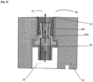
Fig. 4 ] est une vue schématique de coupe transversale du répartiteur selon l'invention. - [
Fig. 5 ] est une vue schématique d'un moyen de contrôle de flux de gaz selon l'invention. - [
Fig. 6 ] est une vue schématique d'un moyen de contrôle de flux de gaz selon l'invention. - [
Fig. 7 ] est une vue schématique d'un joint d'étanchéité destiné à être fixé entre le répartiteur et la culasse.
- [
Fig. 1 ] is a schematic view of an air intake circuit attached to an engine cylinder head. - [
Fig. 2 ] is a schematic cross-sectional view of a cylinder head with a distributor at the end of an exchanger fixed to a cylinder head according to the invention. - [
Fig. 3 ] is a schematic view of the distributor according to the invention. - [
Fig. 4 ] is a schematic cross-sectional view of the distributor according to the invention. - [
Fig. 5 ] is a schematic view of a gas flow control means according to the invention. - [
Fig. 6 ] is a schematic view of a gas flow control means according to the invention. - [
Fig. 7 ] is a schematic view of a seal intended to be fixed between the distributor and the cylinder head.
Dans la description qui va suivre, des chiffres de référence identiques désignent des pièces identiques ou ayant des fonctions similaires.In the description which follows, identical reference numbers designate identical parts or having similar functions.
On désigne par axe vertical un axe orthogonal au plan inférieur de contact de la culasse avec un carter-cylindre, l'axe étant tourné vers le haut à l'opposé du carter-cylindre.The term vertical axis denotes an axis orthogonal to the lower plane of contact of the cylinder head with a cylinder block, the axis being turned upwards away from the cylinder block.
De manière connue, un moteur thermique de véhicule est alimenté en air par un circuit d'admission. Ainsi de l'air est capté depuis la face avant du véhicule et conduit jusqu'à une paroi d'admission du moteur, notamment d'une culasse dudit moteur. L'air peut passer par exemple par un filtre à air, par un étage de compression qui peut-être un compresseur d'un turbo-compresseur. L'air d'admission est ensuite refroidi pour assurer une meilleure efficacité du moteur, en passant par un échangeur de chaleur 50 comme représenté en
On connait les moteurs thermiques à injection directe dans lesquels un injecteur de carburant pulvérise du carburant directement dans la chambre à combustion 53. Ce type de moteur nécessite un injecteur de carburant de forte puissance pour faire face aux pressions élevées dans la chambre à combustion.We know direct injection heat engines in which a fuel injector sprays fuel directly into the
On connait les moteurs thermiques à injection indirecte dans lesquels un injecteur 60 injecte du carburant dans le circuit d'admission d'air en amont selon le sens de circulation d'air de la chambre à combustion. Le carburant n'est pas injecté dans le cylindre mais en amont, dans un canal d'admission 52 ou dans le répartiteur 10 pour que le carburant se mélange avec l'air ou les gaz d'admission de manière homogène avant l'admission dans la chambre à combustion. Cela permet d'avoir une meilleure combustion et donc moins de particules fines qui sont un des problèmes des moteurs modernes. Le carburant se vaporise sous l'effet de la chaleur et brûle de manière optimale une fois arrivé dans la chambre de combustion.We know of indirect injection heat engines in which an
Notre invention concerne un moteur thermique à injection indirecte. Le carburant est injecté par un injecteur dans un canal d'admission d'air 60, plus précisément, l'injecteur est logé dans un conduit d'injection 54 qui débouche dans un canal d'admission 52 d'air de la culasse 50.Our invention relates to an indirect injection heat engine. The fuel is injected by an injector into an
Selon la
Ledit enfoncement 55 est divisé par au-moins une paroi de séparation 56, en au-moins une cavité d'admission 57. Chacune des cavités 57 est connectée à une unique chambre de combustion 53 par les canaux d'admission 52, et ladite chambre à combustion n'est connectée qu'à une seule cavité d'admission 57. De façon claire, le couple (cavité d'admission, chambre à combustion) est unique.Said
La paroi de séparation 56 s'étend depuis la surface de l'enfoncement 55 de la culasse vers l'extérieur, parallèlement à un plan formé par l'axe d'écoulement de l'air d'admission X et un axe vertical Z. La direction d'écoulement d'air est désignée par une flèche.The
Selon les
La bride fait office de répartiteur 10 et le plénum comprend 'espace de passage d'air 13. On utilisera par la suite les noms de bride ou de répartiteur pour définir la même pièce qui assure la fixation de l'échangeur et qui permet le mélange des gaz avant leur admission dans les canaux d'admission de la culasse, selon la fonction assurée.The flange acts as a
La bride 10 comprend un trottoir 18 périphérique de fixation qui est destiné en appui contre la paroi d'admission 51 de la culasse. Dans le trottoir de fixation 18 sont aménagés des orifices traversant pour recevoir des vis de fixation qui sont enfoncées dans la paroi d'admission 51 de la culasse.The
Le répartiteur 10 comprend des cloisons intérieures 19 de séparation sensiblement parallèles aux parois latérales 17, lesdites cloisons intérieures 19 sont dans le prolongement des parois de séparation 56 dans l'enfoncement 55 de la culasse. Les closions intérieures 19 divisent l'espace de passage d'air 13 en compartiments de passage d'air 20. Ainsi chaque compartiment 20 est isolé de façon aéraulique du compartiment voisin et est connecté à une unique cavité 57 d'admission de la culasse et donc à une unique chambre de combustion 53 quand le répartiteur est monté fixé contre la culasse. Plus précisément la cavité d'admission 57 de la culasse est dans le prolongement de façon sensiblement rectiligne du compartiment de passage 20 du répartiteur 10.The
De manière préférentielle, un joint d'étanchéité aéraulique est disposé entre le répartiteur 10 et la paroi d'admission 51 de la culasse 50. Plus précisément, la section de passage du répartiteur est entourée par le joint comme représenté en
Une rampe d'alimentation 21 de gaz déshuilés est creusée dans la paroi inférieure 15 de la bride 10. Ladite rampe 21 est plus précisément formée par une tranchée creusée dans le trottoir de fixation 18. La rampe présente donc une ouverture 21l s'étendant sur toute la longueur de la rampe d'alimentation 21 et destinée en vis-à-vis avec la paroi de fixation 51 de la culasse 50.A
La rampe d'alimentation 21 est prolongée de façon transversale à son axe par des conduits d'amenée 22 de gaz déshuilés qui débouchent de la paroi inférieure 15 dans le plénum 11 par des ouvertures de gaz déshuilés 23. Le diamètre des ouvertures est de l'ordre de quelques millimètres par exemple 5 mm.The
Les ouvertures 23 des conduits d'amenée 22 dans le plénum 11 sont contrôlés par un dispositif d'admission 100 des gaz déshuilés. Ce dispositif permet d'assurer une étanchéité aéraulique de chaque compartiment de passage 20.The
Pour assurer l'étanchéité aéraulique du répartiteur, le trottoir périphérique 18 comprend rainure périphérique 24 destinée à accueillir un joint d'étanchéité 30.To ensure the airtightness of the distributor, the
Selon l'invention, afin d'assurer l'isolation de chaque compartiment, la rampe d'alimentation 21 connectée à tous les compartiments 20 de passage du plénum est étanche par rapport au plénum 11.According to the invention, in order to ensure the insulation of each compartment, the
La paroi inférieure 15 du répartiteur 10 comprend un bord supérieur 15s délimitant le plénum et un bord inférieur 15i tourné vers l'extérieur du répartiteur.The
Sur la paroi inférieure 15 du répartiteur 10 la rainure périphérique 24 comprend deux branches de rainures 25, 26 aptes à accueillir chacune un jonc d'étanchéité 31,32 et entourant totalement la rampe d'alimentation 21. Une première cannelure 25 s'étend transversalement à l'axe d'écoulement des gaz, de façon sensiblement parallèle à la rampe d'alimentation 21 et elle est disposée entre la rampe d'alimentation 21 et le bord supérieur 15s de la paroi inférieure 15. Une deuxième cannelure 32 entoure la rampe 21 et s'étend également transversalement à l'axe d'écoulement des gaz et d'air d'admission, de façon sensiblement parallèle à la rampe d'alimentation 21 ; elle est disposée entre la rampe d'alimentation 21 et le bord inférieur 15i de la paroi inférieure 15.On the
Un premier jonc 31 d'étanchéité est disposé dans la première cannelure 25. Le premier jonc assure l'étanchéité du plénum 11 vis-à-vis de la rampe d'alimentation 21. Un deuxième jonc d'étanchéité 32 est disposé dans la deuxième cannelure 26. Le deuxième jonc 32 assure l'étanchéité de la partie basse du répartiteur en particulier de la rampe 21 de gaz déshuilés vis-à-vis de l'extérieur du répartiteur.A
Selon la
Selon un premier mode de réalisation représenté en
Selon un deuxième mode de réalisation représenté en
Selon un troisième mode de réalisation représenté en
Ainsi chaque compartiment de passage d'air 24 est isolé de façon aéraulique du (ou des) compartiment(s) voisin(s). La rampe d'alimentation 21 de gaz déshuilés étant connectée à tous les compartiments 24 de passage ne présente plus de risque de connexion aéraulique entre des compartiments 24.Thus each
Le dispositif d'admission permet le passage des gaz déshuilés lors des phases ouvertures de soupapes d'admission pendant lesquelles on peut observer une dépression pouvant atteindre 800 mbar.The intake device allows the passage of deoiled gases during the opening phases of the intake valves during which a depression of up to 800 mbar can be observed.
Lors de ces phases, selon le premier mode de réalisation, la membrane élastique est aspirée ce qui entraine le passage des gaz déshuilés dont le niveau de pression est de l'ordre de 950mbar. Les gaz déshuilés sont alors aspirés dans les canaux d'admission de la culasse.During these phases, according to the first embodiment, the elastic membrane is sucked in, which causes the passage of de-oiled gases whose pressure level is of the order of 950 mbar. The deoiled gases are then sucked into the intake channels of the cylinder head.
Lors de ces phases, selon le deuxième mode de réalisation, les lèvres du clapet anti-retour se séparent du fait de la différence de pression entre la rampe d'alimentation et le plénum pour laisser les gaz déshuilés être aspirés et passer au travers de l'ouverture.During these phases, according to the second embodiment, the lips of the non-return valve separate due to the pressure difference between the supply rail and the plenum to allow the deoiled gases to be sucked in and pass through the 'opening.
Puis lors des phases de refoulement, la pression dans le plénum est supérieure à la pression dans la rampe d'alimentation et vient selon le mode de réalisation plaquer la membrane sur la paroi inférieure 15 du répartiteur ou de plaquer les lèvres du clapet l'une contre l'autre pour obturer l'ouverture du débouché du conduit d'amenée.Then during the discharge phases, the pressure in the plenum is greater than the pressure in the supply rail and, depending on the embodiment, presses the membrane on the
L'objectif est atteint : le dispositif 100 d'admission des gaz déshuilés peut contrôler facilement et à couts faible l'étanchéité aéraulique de chaque compartiment de passage 24 d'air, notamment en obturant les conduits d'amenée 22 lors des phases de refoulement.The objective is achieved: the de-oiled
Comme il va de soi, l'invention ne se limite pas aux seules formes d'exécution de cette prise, décrites ci-dessus à titre d'exemples, elle en embrasse au contraire toutes les variantes.As it goes without saying, the invention is not limited only to the forms of execution of this grip, described above by way of examples, on the contrary it embraces all the variants.
Par exemple, le dispositif 100 peut comprend des volets basculants permettant une ouverture lors des phases d'aspirations et d'obturation.For example, the
Par exemple le joint d'étanchéité peut être un joint à base de silicone déposé sur la surface du trottoir de fixation et ne nécessitant pas de rainure périphérique.For example, the seal may be a silicone-based seal deposited on the surface of the fixing pavement and not requiring a peripheral groove.
La culasse ne comporte pas d'enfoncement qui fait partie du plénum et le canaux d'admission débouchent directement dans le répartiteur.The cylinder head does not have a recess which is part of the plenum and the intake channels open directly into the distributor.
Claims (7)
- An indirect fuel injection internal combustion engine with an air intake distributor (10) for the indirect fuel injection internal combustion engine, comprising a cylinder head (50) wherein tubular intake ducts (52) are hollowed out, which open on one side into an intake chamber (11) surrounded by the intake distributor, and on the opposite side into a combustion chamber (53) delimited by a cylinder, a piston and the lower wall of the cylinder head, said distributor comprising inlet orifices (23) for a de-oiled gas feed ramp (21), the intake chamber (11) being divided into air passage compartments (20), each of which is dedicated to a cylinder and comprises an intake device (100) for de-oiled gases capable of controlling the aeraulic seal between two adjacent compartments (20), the inlet device (100) being able to prevent the passage of gas and air from the corresponding compartment (20) to the de-oiled gas feed ramp (21), the device (100) allowing the passage of de-oiled gas from the feed ramp (21) to the corresponding air passage compartment (20), characterized in that the device (100) is housed in a fixing wall (15) of the distributor (10) against the cylinder head (50), the device (100) comprising elastic gas flow control means (34, 35), the feed ramp (21) being surrounded by a seal (30) comprising an upper bead (31) extending substantially parallel to the ramp and placed between the ramp and the intake chamber (11), and a lower bead (32) extending substantially parallel to the ramp and disposed between the ramp (21) and the outside of the distributor, the upper seal bead (31) carrying the resilient gas flow control means (34, 35).
- The internal combustion engine according to the preceding claim, characterized in that the device (100) is arranged at the edge of the wall (15) securing the distributor (10) to the cylinder head (50).
- The internal combustion engine according to any one of claims 1 to 2, characterized in that the feed ramp (21) is recessed in the distributor (10).
- The internal combustion engine according to claim 3,
characterized in that the feed ramp (21) has a longitudinal opening (21l) running the length of the ramp (21) and intended to face the cylinder head (50). - The internal combustion engine according to any one of claims 1 to 4, characterized in that the device (100) comprises an elastic membrane (34) covering the de-oiled gas inlet opening.
- The internal combustion engine according to any one of claims 1 to 5, characterized in that the device (100) comprises a check valve (35) arranged in a feed duct (23) connected to the feed ramp (21) on one side and to the intake chamber (11) on the opposite side.
- The internal combustion engine according to any of the preceding claims, characterized in that the upper bead (31) and the lower bead (32) are housed respectively in a top spline (25) and a bottom spline (26) recessed in the bottom wall (15) of the distributor (10) and extending substantially parallel to the feed ramp (21).
Applications Claiming Priority (1)
| Application Number | Priority Date | Filing Date | Title |
|---|---|---|---|
| FR1915168A FR3105308B1 (en) | 2019-12-20 | 2019-12-20 | DISTRIBUTOR with integrated Blowby gas return ramp |
Publications (2)
| Publication Number | Publication Date |
|---|---|
| EP3839239A1 EP3839239A1 (en) | 2021-06-23 |
| EP3839239B1 true EP3839239B1 (en) | 2024-05-29 |
Family
ID=69903541
Family Applications (1)
| Application Number | Title | Priority Date | Filing Date |
|---|---|---|---|
| EP20212384.0A Active EP3839239B1 (en) | 2019-12-20 | 2020-12-08 | Combustion engine with manifold with integrated blow-by rail |
Country Status (2)
| Country | Link |
|---|---|
| EP (1) | EP3839239B1 (en) |
| FR (1) | FR3105308B1 (en) |
Family Cites Families (8)
| Publication number | Priority date | Publication date | Assignee | Title |
|---|---|---|---|---|
| US7370645B2 (en) * | 2004-05-28 | 2008-05-13 | Ford Global Technologies, Llc | Variable stiffness flow control valve |
| DE102004056442A1 (en) * | 2004-11-23 | 2006-05-24 | Mann + Hummel Gmbh | Gas transfer arrangement with throttle bore |
| FR2884875A1 (en) | 2005-04-21 | 2006-10-27 | Renault Sas | Air intake system for combustion chamber of e.g. petrol engine, has injector of indirect injection type, and synchronizing unit to synchronize opening of scavenging and intake valves with respect to opening of exhaust valve |
| JP2008240521A (en) * | 2007-03-23 | 2008-10-09 | Honda Motor Co Ltd | Air-intake control device for internal combustion engine |
| US8122864B2 (en) * | 2009-05-22 | 2012-02-28 | Ford Global Technologies | Intake manifold for multicylinder internal combustion engine |
| JP5490562B2 (en) * | 2010-02-19 | 2014-05-14 | 愛三工業株式会社 | PCV valve mounting structure |
| FR2958337B1 (en) * | 2010-03-31 | 2013-03-01 | Valeo Systemes Thermiques | MANIFOLD FOR GAS DISTRIBUTION IN THE CYLINDER HEAD OF AN ENGINE, ASSEMBLY OF A DISTRIBUTION MANIFOLD AND A CYLINDER HEAD. |
| JP2016079896A (en) * | 2014-10-17 | 2016-05-16 | アイシン精機株式会社 | Air-intake apparatus |
-
2019
- 2019-12-20 FR FR1915168A patent/FR3105308B1/en active Active
-
2020
- 2020-12-08 EP EP20212384.0A patent/EP3839239B1/en active Active
Also Published As
| Publication number | Publication date |
|---|---|
| EP3839239A1 (en) | 2021-06-23 |
| FR3105308A1 (en) | 2021-06-25 |
| FR3105308B1 (en) | 2022-12-23 |
Similar Documents
| Publication | Publication Date | Title |
|---|---|---|
| FR2931517A1 (en) | GAS ADMISSION DEVICE | |
| EP2012061A1 (en) | Chamber dome deflector, combustion chamber comprising the same and gas turbine engine equipped with the same | |
| FR2738288A1 (en) | CYLINDER HEAD FOR AN INTERNAL COMBUSTION ENGINE COOLED BY LIQUID AND HAVING MULTIPLE CYLINDERS | |
| EP1831535A1 (en) | Device for trapping combustion air of an internal combustion engine | |
| EP3839239B1 (en) | Combustion engine with manifold with integrated blow-by rail | |
| EP3707365A1 (en) | Air intake device for a heat engine | |
| EP3999731B1 (en) | Distributor with semi-integrated flow separation | |
| EP2469067B1 (en) | Casing for intake module, in particular for the intake module of an automobile combustion engine, and intake module including such a casing | |
| EP3877632B1 (en) | Blow-by diffusion device at intake of cylinder head | |
| EP2469066B1 (en) | Manifold for distributing gas in the intake ducts of a heat engine of an automobile and intake module provided with such a manifold | |
| WO2021008786A1 (en) | Distributor with integrated flow separation | |
| FR2973071A1 (en) | Oil decanter for separating liquid and gas phases of blow-by gas in e.g. positive-ignition engine, has casing internally defining cooling channel for passage of coolant, where channel is hermetically isolated from decantation chamber | |
| FR3098866A1 (en) | Distributor with integrated flow and duct separation | |
| FR3082241A1 (en) | INTAKE DISTRIBUTOR FOR A HEAT ENGINE WITH RECIRCULATED GAS MIXING DEVICE | |
| FR3103015A1 (en) | Deoiled gas inlet device at the inlet of a cylinder head with deflectors | |
| EP3976947B1 (en) | Notch on a cylinder head inlet surface for oblique attachment on an engine cylinder head | |
| WO2018146413A1 (en) | Cylinder head comprising an exhaust gas injection assembly | |
| FR3126454A1 (en) | Optimized water-air heat exchanger | |
| EP2299100B1 (en) | Intake manifold with integrated crankcase ventilation and vehicle comprising such an intake manifold | |
| EP2469068A1 (en) | Casing for intake module, in particular for the intake module of an automobile combustion engine, and intake module including such a casing | |
| FR3026788A3 (en) | COOLING HEAT EXHAUST PONTET | |
| EP4069951A1 (en) | Oil decanter comprising a fresh air chamber | |
| EP3492729A1 (en) | Cylinder head of a motor vehicle comprising an integrated exhaust manifold | |
| FR3096406A1 (en) | boss on cylinder head intake face for obliquely fixing on crankcase cylinder head | |
| EP3211193A1 (en) | Cooling interfaces for internal combustion engine |
Legal Events
| Date | Code | Title | Description |
|---|---|---|---|
| PUAI | Public reference made under article 153(3) epc to a published international application that has entered the european phase |
Free format text: ORIGINAL CODE: 0009012 |
|
| STAA | Information on the status of an ep patent application or granted ep patent |
Free format text: STATUS: THE APPLICATION HAS BEEN PUBLISHED |
|
| AK | Designated contracting states |
Kind code of ref document: A1 Designated state(s): AL AT BE BG CH CY CZ DE DK EE ES FI FR GB GR HR HU IE IS IT LI LT LU LV MC MK MT NL NO PL PT RO RS SE SI SK SM TR |
|
| STAA | Information on the status of an ep patent application or granted ep patent |
Free format text: STATUS: REQUEST FOR EXAMINATION WAS MADE |
|
| 17P | Request for examination filed |
Effective date: 20210707 |
|
| RBV | Designated contracting states (corrected) |
Designated state(s): AL AT BE BG CH CY CZ DE DK EE ES FI FR GB GR HR HU IE IS IT LI LT LU LV MC MK MT NL NO PL PT RO RS SE SI SK SM TR |
|
| RAP3 | Party data changed (applicant data changed or rights of an application transferred) |
Owner name: RENAULT S.A.S |
|
| RAP3 | Party data changed (applicant data changed or rights of an application transferred) |
Owner name: RENAULT S.A.S |
|
| P01 | Opt-out of the competence of the unified patent court (upc) registered |
Effective date: 20230608 |
|
| GRAP | Despatch of communication of intention to grant a patent |
Free format text: ORIGINAL CODE: EPIDOSNIGR1 |
|
| STAA | Information on the status of an ep patent application or granted ep patent |
Free format text: STATUS: GRANT OF PATENT IS INTENDED |
|
| INTG | Intention to grant announced |
Effective date: 20231222 |
|
| RAP1 | Party data changed (applicant data changed or rights of an application transferred) |
Owner name: NEW H POWERTRAIN HOLDING, S.L.U. |
|
| GRAS | Grant fee paid |
Free format text: ORIGINAL CODE: EPIDOSNIGR3 |
|
| GRAA | (expected) grant |
Free format text: ORIGINAL CODE: 0009210 |
|
| STAA | Information on the status of an ep patent application or granted ep patent |
Free format text: STATUS: THE PATENT HAS BEEN GRANTED |
|
| AK | Designated contracting states |
Kind code of ref document: B1 Designated state(s): AL AT BE BG CH CY CZ DE DK EE ES FI FR GB GR HR HU IE IS IT LI LT LU LV MC MK MT NL NO PL PT RO RS SE SI SK SM TR |
|
| REG | Reference to a national code |
Ref country code: CH Ref legal event code: EP |
|
| REG | Reference to a national code |
Ref country code: IE Ref legal event code: FG4D Free format text: LANGUAGE OF EP DOCUMENT: FRENCH |
|
| REG | Reference to a national code |
Ref country code: DE Ref legal event code: R096 Ref document number: 602020031591 Country of ref document: DE |
|
| REG | Reference to a national code |
Ref country code: LT Ref legal event code: MG9D |
|
| REG | Reference to a national code |
Ref country code: NL Ref legal event code: MP Effective date: 20240529 |
|
| PG25 | Lapsed in a contracting state [announced via postgrant information from national office to epo] |
Ref country code: IS Free format text: LAPSE BECAUSE OF FAILURE TO SUBMIT A TRANSLATION OF THE DESCRIPTION OR TO PAY THE FEE WITHIN THE PRESCRIBED TIME-LIMIT Effective date: 20240929 |
|
| PG25 | Lapsed in a contracting state [announced via postgrant information from national office to epo] |
Ref country code: BG Free format text: LAPSE BECAUSE OF FAILURE TO SUBMIT A TRANSLATION OF THE DESCRIPTION OR TO PAY THE FEE WITHIN THE PRESCRIBED TIME-LIMIT Effective date: 20240529 |
|
| PG25 | Lapsed in a contracting state [announced via postgrant information from national office to epo] |
Ref country code: FI Free format text: LAPSE BECAUSE OF FAILURE TO SUBMIT A TRANSLATION OF THE DESCRIPTION OR TO PAY THE FEE WITHIN THE PRESCRIBED TIME-LIMIT Effective date: 20240529 Ref country code: HR Free format text: LAPSE BECAUSE OF FAILURE TO SUBMIT A TRANSLATION OF THE DESCRIPTION OR TO PAY THE FEE WITHIN THE PRESCRIBED TIME-LIMIT Effective date: 20240529 |
|
| PG25 | Lapsed in a contracting state [announced via postgrant information from national office to epo] |
Ref country code: GR Free format text: LAPSE BECAUSE OF FAILURE TO SUBMIT A TRANSLATION OF THE DESCRIPTION OR TO PAY THE FEE WITHIN THE PRESCRIBED TIME-LIMIT Effective date: 20240830 |
|
| REG | Reference to a national code |
Ref country code: AT Ref legal event code: MK05 Ref document number: 1690838 Country of ref document: AT Kind code of ref document: T Effective date: 20240529 |